EP1933451B1 - Submarine with electrical power supply circuit - Google Patents
Submarine with electrical power supply circuit Download PDFInfo
- Publication number
- EP1933451B1 EP1933451B1 EP07019996A EP07019996A EP1933451B1 EP 1933451 B1 EP1933451 B1 EP 1933451B1 EP 07019996 A EP07019996 A EP 07019996A EP 07019996 A EP07019996 A EP 07019996A EP 1933451 B1 EP1933451 B1 EP 1933451B1
- Authority
- EP
- European Patent Office
- Prior art keywords
- frequency
- power
- inverters
- voltage
- submarine according
- Prior art date
- Legal status (The legal status is an assumption and is not a legal conclusion. Google has not performed a legal analysis and makes no representation as to the accuracy of the status listed.)
- Active
Links
- 230000003068 static effect Effects 0.000 claims description 25
- 238000009826 distribution Methods 0.000 claims description 13
- 230000036961 partial effect Effects 0.000 claims description 12
- 238000010586 diagram Methods 0.000 claims description 8
- 230000004807 localization Effects 0.000 claims description 4
- 238000001514 detection method Methods 0.000 claims description 3
- 238000006073 displacement reaction Methods 0.000 claims description 3
- 238000004891 communication Methods 0.000 description 10
- 230000002950 deficient Effects 0.000 description 10
- 230000001419 dependent effect Effects 0.000 description 5
- 230000006870 function Effects 0.000 description 5
- 238000000034 method Methods 0.000 description 4
- 238000011084 recovery Methods 0.000 description 4
- 230000001360 synchronised effect Effects 0.000 description 4
- 230000000694 effects Effects 0.000 description 2
- 239000000446 fuel Substances 0.000 description 2
- 239000011159 matrix material Substances 0.000 description 2
- 238000005259 measurement Methods 0.000 description 2
- 238000012544 monitoring process Methods 0.000 description 2
- 230000001681 protective effect Effects 0.000 description 2
- 230000001105 regulatory effect Effects 0.000 description 2
- 239000002699 waste material Substances 0.000 description 2
- 230000003247 decreasing effect Effects 0.000 description 1
- 238000011156 evaluation Methods 0.000 description 1
- 230000002035 prolonged effect Effects 0.000 description 1
- 230000002829 reductive effect Effects 0.000 description 1
- 238000000926 separation method Methods 0.000 description 1
- 230000002123 temporal effect Effects 0.000 description 1
- 238000012360 testing method Methods 0.000 description 1
- 239000013598 vector Substances 0.000 description 1
Images


Classifications
-
- B—PERFORMING OPERATIONS; TRANSPORTING
- B63—SHIPS OR OTHER WATERBORNE VESSELS; RELATED EQUIPMENT
- B63G—OFFENSIVE OR DEFENSIVE ARRANGEMENTS ON VESSELS; MINE-LAYING; MINE-SWEEPING; SUBMARINES; AIRCRAFT CARRIERS
- B63G8/00—Underwater vessels, e.g. submarines; Equipment specially adapted therefor
- B63G8/08—Propulsion
-
- H—ELECTRICITY
- H02—GENERATION; CONVERSION OR DISTRIBUTION OF ELECTRIC POWER
- H02H—EMERGENCY PROTECTIVE CIRCUIT ARRANGEMENTS
- H02H7/00—Emergency protective circuit arrangements specially adapted for specific types of electric machines or apparatus or for sectionalised protection of cable or line systems, and effecting automatic switching in the event of an undesired change from normal working conditions
- H02H7/26—Sectionalised protection of cable or line systems, e.g. for disconnecting a section on which a short-circuit, earth fault, or arc discharge has occured
- H02H7/268—Sectionalised protection of cable or line systems, e.g. for disconnecting a section on which a short-circuit, earth fault, or arc discharge has occured for dc systems
Definitions
- the invention relates to a submarine with an electrical system.
- the electrical system is usually powered by inverters, which convert the output from the batteries or a fuel cell system DC voltage in AC voltage (AC or three-phase).
- inverters which convert the output from the batteries or a fuel cell system DC voltage in AC voltage (AC or three-phase).
- AC or three-phase AC voltage
- several power inverters or inverters are always used here.
- the electrical systems in submarines are usually divided into two or more subnets, which are each powered by an inverter with power.
- at least one additional reserve inverter is additionally provided, which is not constantly in operation and can optionally be switched to one of the subnetworks if the local inverter should fail.
- To further increase the reliability can also be possible to switch the two subnets together, so that they are powered by a common inverter with power.
- the disadvantage of this concept that inherent switching times are given, which allow only a conditional freedom from interruption of the power supply, which can lead to data loss, relay waste, equipment failure and the like may occur when switching.
- WO 98/48497 discloses an electrical vehicle electrical system for ships with a protective computer for quickly switching off short-circuit affected network areas. For this purpose, the current flowing in individual network areas currents are detected and added by current sensors according to amount and phase. At the amount of the added current vectors, a short circuit case can be detected.
- the submarine on an electrical system with at least two converter devices or inverters, which convert the example provided by a battery DC voltage in AC voltage for the electrical system. It is provided that the at least two inverters simultaneously feed a common busbar. That is, the usual separation of the electrical system in several subnets with separate busbars, which are each fed by only one inverter, is abandoned here.
- a synchronization is provided according to the invention, which manages without direct communication between the inverters or a higher-level central control.
- each inverter having an independent controller that ensures that the associated inverter is synchronized to the grid.
- the control device of each inverter is designed so that it can capture current electrical characteristics on the busbar and then set the associated inverter and in particular its output voltage and frequency so that the inverter synchronously with the other inverters on the same busbar the network fed. That is, each inverter automatically performs an adjustment of its output voltage and frequency depending on its independent control device the characteristics detected by the control device.
- inverters which continuously record the characteristics of the vehicle electrical system and synchronize themselves continuously to the electrical system, in order to take over its function largely uninterruptible in the event of a failure of another inverter. Since the individual inverters are independent, d. H. operate without direct connection, direct communication or higher-level control, there are according to the invention no additional connecting or higher-level components for joint operation of the inverter, which could lead to total failure of the entire system in case of failure. Furthermore, all inverters and their control devices are preferably identical and equal in operation. Thus, in contrast to a master / slave control, the failure of an inverter can not lead to total failure.
- each control device has a detection module for detecting the electrical characteristics on the busbar. These are in particular mains voltages and mains currents at the busbar. In this case, total voltages or total currents or individual voltages and individual currents can be recorded for each phase.
- each control device preferably has a calculation module for calculating derived parameters, in particular the active and reactive power as well as the frequency and the output terminal voltage, based on the detected electrical characteristics. These derived parameters can then be used as the basis for the further regulation.
- Each control device has a control module, which is designed to control the output voltage of the associated inverter based on the characteristics and / or the derived characteristics. This makes it possible for the control device to regulate the associated inverter solely on the basis of the parameters detected by this inverter itself or of the parameters derived from these characteristics, so that the inverter can automatically synchronize with the vehicle electrical system. There are thus no external and in particular no higher-level control devices required.
- the control module of each control device has a primary controller, in which static characteristic curves are stored for the inverter, on the basis of which the control variables for the primary controller are determined in the control module.
- the static characteristic curves may in particular be a voltage reactive power diagram and / or a frequency active power diagram, from which the reactive power and / or the effective power are determined as command values for the subsequent control as command values dependent on the detected characteristics and / or the parameters derived therefrom ,
- the active power of the frequency control and the reactive power of the voltage control is used.
- the static characteristics are permanently assigned to the inverters and ensure that the inverters have a certain behavior on the network, which is preferably close to that of a synchronous generator.
- the characteristic curves are selected such that they are not constant but drop off depending on the load, ie a decay coefficient exhibit. This load-dependent course of the characteristic curves makes it possible for two or more inverters in the same on-board network to be located or regulated so that they can dine synchronously together with the vehicle electrical system.
- the primary controller preferably has a reactive power regulator and an active power regulator, which as stated serve to regulate the frequency and the voltage at the output of the inverter.
- control module preferably has an output voltage regulator, to which the controlled variables of the reactive power controller and the active power controller, in particular frequency and voltage, are supplied as reference variables.
- the output voltage regulator then adjusts the output voltages and frequencies preferably for all phases as a function of these reference variables.
- each control device is equipped with at least one secondary controller, which can effect or make a parallel shift of the stored in the primary controller static characteristic based on the characteristics or derived from these parameters to achieve predetermined setpoints in particular of frequency and voltage at a given power. Due to the load-dependent curve of the characteristic described above, system deviations occur. To be able to achieve the high demands on the power quality of submarines, these control deviations should be avoided or minimized due to the declining course of the static characteristics. This can be done by the secondary controller, which ensure that the characteristics are shifted so that setpoint voltage and setpoint frequency are maintained at the currently occurring power.
- the secondary controllers are equipped with a balancing device for symmetrizing the load distribution.
- the balancing devices are also designed so that they work independently of the balancing devices of the other inverters for each inverter, d. H. There is no direct communication or higher-level control or regulation of the inverter to balance the load distribution.
- the balancing device is preferably designed such that it detects the ratio of the output power of the associated inverter to the total power at the busbar and registers changes in this ratio. Depending on a change in this ratio, the balancing device can also effect a parallel displacement of the static characteristic stored in the primary regulator in order to achieve the setpoint values, in particular of frequency and voltage for a given power.
- the secondary regulators of the individual inverters cause, by their independent control, a swinging between balancing and restoring of the setpoint frequency and setpoint voltage in the vehicle electrical system, so that a constant frequency with symmetrical load distribution in the electrical system can be achieved overall by this swinging out.
- any inverter performs an adjustment of its power to adjust the output power of the changed load.
- the setpoint frequency is restored in the electrical system, which in turn is then registered by another inverter as a load change.
- the Balancing device active and provides a power adjustment of the second inverter. This is in turn perceived by the first inverter as a load change, so that this in turn carries out a power adjustment, so that both inverters can then settle on a symmetrical load distribution at the nominal frequency.
- this procedure works accordingly.
- the remaining inverters on the busbar are set to a constant frequency and even load distribution.
- Each control device preferably has two secondary regulators, one of which serves for frequency regulation and the other for voltage regulation. That is, each of the secondary controllers causes a parallel shift of one of the static characteristics in the primary controller, i. H. the characteristic curve in the voltage reactive power diagram and the characteristic curve in the frequency active power diagram, which indicate the course of the reactive power over the voltage or the effective power over the frequency.
- each control device and in particular each secondary controller, and more preferably the balancing device is equipped with an overload protection, which ensure that a prolonged overload of the inverter is avoided and possibly the inverter switches off prematurely.
- the largely uninterruptible power supply is also made possible by an improved protection concept.
- the protection concept should definitely ensure that it does not lead to a total failure of the entire electrical system. This is particularly preferred when a common vehicle electrical system is fed by a plurality of inverters, as described above, ie not several separate busbars as provided in the prior art.
- the electrical system is divided into several subnets, which are interconnected in normal operation and operated together. In particular, as described above, they can be fed jointly by a plurality of inverters.
- a busbar circuit breakers are arranged such that by opening the circuit breaker subnets can be separated from the common electrical system or the electrical system can optionally be divided into several subnets to prevent the failure of a part of the electrical system in case of failure in the overall failure of the electrical system to be able to.
- the individual subnetworks are equipped with sensors for continuously recording current characteristics of the individual subnetworks. Furthermore, the sensors and the power switches are connected to a common control device such that sensors and power switches can communicate with the control device and in particular the common control device can switch the power switches.
- the control device is designed such that the power switches are selectively switchable by the control device as a function of the currently detected characteristic data.
- control device in the event that characteristic data is recorded by the sensors which suggest a short circuit in a partial area of the vehicle electrical system, to be disconnected from the vehicle electrical system by opening the associated circuit breaker of this subnetwork in which the short circuit has occurred .
- this can be configured redundantly, so that for example in case of failure of the control device, a second control device can immediately take over their function.
- the characteristics of the individual subnetworks detected by the sensors include the electrical currents in the individual subnetworks.
- the control device detects when the current in a subnetwork reaches a value which indicates that there is a short circuit.
- At least one table is stored in the control device, in each of which the short-circuit currents occurring in the individual subnetworks and / or at the associated sensors or their relationship to one another are stored for the short-circuit case in one of the subnetworks.
- This table uses the knowledge that a short circuit in a subarea of the on-board network or in a subnet usually not only there to a change of the occurring current but also in the other parts of the electrical system and the sensors arranged there to a change in the current comes which is based solely on the geometry of the electrical system.
- different multiples of the occurring short-circuit current and sign of the short-circuit current will occur at the individual measuring points or sensors, which can be detected by the sensors arranged there.
- the occurring state of the currents is preferably stored at all sensors for each short circuit, so that from this stored image of the occurring short-circuit currents at the individual sensors can be inversely closed on the basis of the table, in which part of the electrical system of the short circuit has occurred.
- each short-circuiting case has a clearly assignable image of short-circuit currents at all existing sensors, ie, based on this image of the occurring currents, a specific short-circuiting case can be uniquely identified.
- the control device is preferably designed accordingly such that the localization of the short circuit case, i. H. the detection of the subnetwork in which the short circuit has occurred by allocation of the occurring combination or the image of Kun gleichströmen based on the stored table and then the control of the corresponding circuit breaker, which is associated with this subnet, for separating the subnetwork, in which the short-circuit case has been localized, is switchable. That is, the controller can, as in the case of short circuit on all sensors, the amounts and signs of the short-circuit currents occurring there are detected by assignment based on the table where in the subnet the short circuit has occurred and then turn off this subnet by opening the associated circuit breaker.
- the controller can, as in the case of short circuit on all sensors, the amounts and signs of the short-circuit currents occurring there are detected by assignment based on the table where in the subnet the short circuit has occurred and then turn off this subnet by opening the associated circuit breaker.
- one or more tables (s) is / are deposited, in which in each case for the short circuit in one of the subnets occurring in the individual subnets and / or the associated sensors short-circuit currents or their ratio to each other in the event that one or more specific circuit breakers are opened.
- These additional tables take account of short-circuit cases that occur when subnets are already disconnected from the vehicle electrical system by opening the associated circuit breakers. In this case, the short-circuit currents occurring at the individual sensors can change the magnitude and sign compared to the case in which all circuit breakers are closed and all subnetworks are on the vehicle electrical system.
- the controller can then on the occurrence of another short circuit case after opening a particular circuit breaker on the basis of the additional table, which reproduces the image of the short-circuit currents in the open state of a particular circuit breaker or more specific circuit breakers, the place or the subnet of this renewed Locate short circuit case.
- the control device can then open the circuit breaker of this subnetwork in which the short circuit has occurred in order to disconnect this subnetwork from the vehicle electrical system.
- control device is designed such that after switching a circuit breaker for disconnecting a subnet for subsequent localization of short circuit cases, a modified table is used, which takes into account the open state of the circuit breaker.
- the sensors are integrated in the circuit breaker. That is, it is intelligent circuit breaker, which are simultaneously able to state variables, in particular to be able to detect the power in the line they switch, and to be able to transmit to a central control device.
- the circuit breakers are equipped with a corresponding communication interface, which transmits to a control device detected by the sensor characteristics and on the other hand can receive switching commands from the control device, which allow opening and / or closing of the circuit breaker.
- the protection concept makes it possible to precisely locate faults in the vehicle electrical system and to quickly disconnect the subnetworks in which faults have occurred from the vehicle electrical system without interrupting the power supply in the rest of the vehicle electrical system.
- By the central control of the circuit breaker in the manner described selectivity of the switch is achieved. This ensures a quasi-uninterruptible power supply.
- the interruption of the power supply is ideally limited to the physical minimum, ie to the moment of the short circuit.
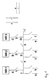
- Fig. 1 schematically shows the parallel operation of three converters on a common electrical system.
- the current or inverters WR 1 , WR 2 and WR 3 convert the DC voltage provided by the batteries or a fuel cell system into alternating voltage or three-phase current.
- the single-phase version is shown here.
- the switches 1 and 5 are closed, so that a common bus bar 6 is formed.
- the switches 1 and 3 are closed, so that the inverters WR 1 and WR 3 jointly feed the electrical system.
- the switch 2 remains open in normal operation, so that the inverter WR 2 is not connected to the grid and is available as a reserve inverter, which is switched on failure of one of the other inverter WR 1 or WR 3 .
- the bus bar 6 is divided into three sections I, II and III or is divisible by opening the switch.
- circuit breakers 1, 2, 3, 4 and 5 are provided which simultaneously detect these values and can report them to a central control device, which is also responsible for opening and closing the switches 1 to 5.
- the switches 1 to 5 are equipped for this purpose with appropriate communication modules.
- the parallel operation of two inverters for example the inverters WR 1 and WR 3 on a common busbar 6 requires a synchronization of the output voltage and frequency. According to the invention, this is done by independent control devices, which are integrated in the inverters, without a higher-level control or direct communication between the inverters is required. In addition, the inverters are in operation equal, ie there are no dependencies according to the master / slave principle.
- the inverters WR 1 , WR 2 and WR 3 have control devices which automatically detect the vehicle electrical system, ie in particular current and voltage at the busbar 6 and regulate the associated inverter WR 1 , WR 2 or WR 3 so that it automatically on the Network synchronized.
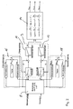
- Fig. 2 shows schematically how this scheme works in principle.
- grid voltages and grid currents are detected by the inverters and in a calculation module 8 of the control unit derived parameters, namely the active and reactive power and frequency and output terminal voltage are calculated based on these characteristics, which serve as reference variables for the subsequent control.
- the calculated frequency of the control of the frequency over the active power controller 10 and the calculated voltage of the regulation of the voltage across the reactive power controller 12.
- Active power controller 6 and reactive power controller 8 are part of a primary controller 9.
- This primary control takes into account static characteristics, which are fixed to the inverter and are stored in a memory of the control device. These are a voltage-reactive power characteristic (Q (U n ) -Statik which is used for voltage regulation, as well as a frequency active power characteristic (P (f) -Statik), which is used for frequency control.
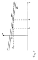
- Fig. 3 is shown as an example of the course of the frequency-effective power statics.
- the course of the voltage-reactive power statics is corresponding. It is important that these are load-dependent characteristics. That is, the characteristic is not a constant, ie horizontal in the diagram, but rather a drop of voltage or frequency with increasing load takes place.
- This embodiment of the characteristics with waste coefficients makes it possible for two inverters with identical control devices to be found in the network so that they can synchronize the grid together.
- the defined statics force the current controller to behave as a controlled synchronous generator.
- the voltage in the network has the frequency f 1 and the amplitude U 1 .
- the associated powers in the network are P 1 and Q 1 (active and reactive power)
- P 1 and Q 1 active and reactive power
- the currents change and the power increases to P 2 and Q 2 , but the voltage amplitude initially remains at U 1 and the frequency remains at f 1 , since the current or inverter itself can not cause any changes of these sizes. It provides a constant output voltage with constant frequency. This change is only possible through the given statics, the P (f) -statics and the Q (U n ) -statics.
- P 1 and Q 1 are determined as reference variables for the active power controller 10 and the reactive power controller 12.
- the controlled variables have changed to P 2 and Q 2 (measured in the network, ie at the busbar 6). This creates a control difference, which is now compensated by the controller.
- the power controllers ie the active power controller 10 and the reactive power controller 12, generate new values for U q * and ⁇ * ( ⁇ *).
- These form the reference variables for the converter output voltage regulator 14, which on the basis of which they set the new output voltages of the inverter U Soll, 1 , U Soll, 2 and U- Soll , 3 , in the case of a three-phase system. From the temporal change of the angle ⁇ * follows the frequency change.
- the voltage in the network changes, the amplitude becomes U 2 , the frequency becomes f 2 .
- a secondary control is provided in addition to the primary control.
- two secondary controls ie two secondary controllers 16, 18 for frequency secondary control (f-secondary control) and voltage secondary control (U secondary control) are provided.
- These secondary controls cause a shift of the statics stored in the primary controller, ie the P (f) statics and the Q (U n ) statics. This is exemplified by the P (f) -statics in FIG. 4 shown.
- the secondary controllers 16 and 18 each have a "testing" module. This causes a shift of the P (f) -statics by f 0, T or the Q (U n ) -statics by U n0, T. The restoration of the frequency or voltage is initiated by the recovery module. The symmetrization then takes place through the Symmetri mecanicsmodul whose principle rule structure in Fig. 5 is shown.
- the starting frequency is initially f 0 and the active power P 0, for example. If the load is now increased to P 1 , the frequency is reduced to f 1 . If, for example, the control device of the first inverter WR 1 reacts first and restores the frequency f 0 , the second inverter WR 3 will interpret this frequency change as a load change and correspondingly reduce its power output. This then leads to the above-mentioned unbalanced load distribution. To compensate for this, the value P sollS is set to 0 during balancing.
- the ratio of the total load to the individual load of the inverter P / P N is greater and vice versa, the value f 0S smaller (larger in absolute terms , but negative range).
- WR 3 wants to lower its frequency due to the symmetrization, in order to increase its performance again. The lowered frequency then leads to an increase in power in WR 1 only to a smaller extent than in WR 2 . The process thus results in a renewed restoration of the frequency.
- the individual inverters are also the failure of another inverter based on the changes in the parameters in the network, d. H. at the busbar 6 and regulate their output voltage according to amplitude and frequency accordingly to maintain target voltage and frequency in the network.
- the circuit in FIG Fig. 1 a protection concept for the network protection explained according to the invention, which can ensure a virtually uninterruptible power supply, especially in the described parallel operation of two or more inverters on a busbar.
- the circuit breaker 1 to 5 are equipped with sensors or sensors which detect the current at the switching point and transmit to a central control device, not shown. This performs an evaluation, which detects faults, ie short circuits in the network and can locate and then selectively open individual of the switches 1 to 5 to disconnect short-circuited power supplies or subnets can.
- This concept ensures the selectivity of the protective devices in the overall network.
- the protection concept is based on the finding that a fault in the network, ie a short circuit can be detected and localized by a specific combination of the short-circuit currents at the individual measuring points. Since the measuring points are integrated here in the circuit breakers, they are located at the points of the line switch. However, separate sensors or transducers could be provided elsewhere.
- the central control device constantly polls the current values determined at the measuring points of the switches 1 to 5 and evaluates them. For this, the measured values be communicated by communicative circuit breakers, for example via a bus system to the central control device. However, other conventionally available communication paths between circuit breakers and controller are also usable.
- Fig. 6 shows the combinations of occurring short-circuit currents in the circuit according to Fig. 1 , wherein in normal operation, the switches 1, 3, 4 and 5 are closed, that is, the sections I, II and III are connected together to form a common busbar 6 and the inverters WR 1 and WR 3 are in operation.
- the inverter WR 2 is kept as a reserve inverter to take over its function in case of failure of one of the other inverters.
- the appropriate switch can be opened.
- a short circuit in the inverter WR 1 ie at location A
- a negative short-circuit current at the measuring point 1 no short-circuit current at the measuring point 2
- a positive short-circuit current at the measuring point 3 a positive short-circuit current at the measuring point 3 and the simple negative short-circuit current at the measuring points 4 respectively certainly.
- the switch 1 must be opened.
- the switches which are to be opened for switching off the power supply with a short circuit are marked by x. In the event that a short circuit occurs in the busbar section II, z. B. the switches 4 and 5 are opened.
- the table as in Fig. 6 is stored in the central control device and this compares the measured at the measuring points 1 to 5 currents with the table. If there is a combination of currents, which is shown in the table, the controller locates in this way a short circuit at a certain point and causes the triggering of the required switch to disconnect the corresponding short-circuited power supplies. These switches are in Fig. 6 marked with x.
- FIG. 6 The table shown concerns the case that inverters WR 1 and WR 3 are in operation. Accordingly, additional tables may be deposited in the event that other combinations of inverters are in operation, the controller, as it opens and closes the switches, knowing which inverters are on the grid and thus accessing the correct table. Furthermore, matrices or tables similar to those in Fig. 6 also for power converter failures, defective switches or non-tripping switches set up. Such tables are in the FIGS. 7 to 9 shown. So is in Fig. 7 which short-circuit currents occur at the measuring points 1 to 5 in the event that one of the power converters WR 1 , WR 2 or WR 3 (power converter 1, Power converter 2 and power converter 3) fails. Again, to eliminate the error again open the switch marked with x, depending on where the short circuit occurs.
- Fig. 8 shows a table which takes into account the case that one of the switches 1 to 4 is defective, wherein in the table in Fig. 8 all five cases, ie switch 1 defective, switch 2 defective, switch 3 defective, switch 4 defective or switch 5 defective, are shown.
- switch 1 defective, switch 2 defective, switch 3 defective, switch 4 defective or switch 5 defective are shown.
- the inverters WR 1 and WR 3 are in operation and the inverter W 2 is switched off as a reserve inverter by opening the switch 2.
- those switches which are to be opened for the individual case of short circuit to disconnect the corresponding subnet marked with x.
- those switches are marked with y, which are to be opened in the event that one of the switches, which should actually trigger, is defective.
- Fig. 9 shows the combination of short-circuit currents in the event of failure of a switch after the release of the other switch involved in the switching operation.
- Fig. 10 schematically shows a suitable program flow in the control device. It starts with the continuous measurement of the currents at the measuring points in the circuit breakers, in Fig. 1 the bodies 1 to 5. If a specific image of short-circuit currents in accordance with the table in Fig. 6 determined in a first step, which switch must be opened to turn off the part of the network with the short circuit, as determined by Fig. 6 is explained. This takes place in step S1, followed by a renewed measuring of the currents, if a short-circuit is still detected, a new table is taken into account in which the already opened switch is taken into account. Based on this new table is then determined again, which switch must be opened. This takes place in step S2, wherein the corresponding switch must be opened with a time delay.
- step S1b a correspondingly changed table is accessed in step S1b, which takes into account the defective switch or converter and the corresponding pictures of the Short-circuit currents or the corresponding distribution of short-circuit currents contains. This table is used to monitor whether a short circuit occurs and, in the event of a short circuit, locate the short circuit and select the switch to open. Thereafter, a renewed measurement of the currents and in the event that the short circuit persists, in step S2b a renewed monitoring using a modified new table corresponding to the step S2.
Abstract
Description
Die Erfindung betrifft ein Unterseeboot mit einem elektrischen Bordnetz.The invention relates to a submarine with an electrical system.
In Unterseebooten wird das elektrische Bordnetz üblicherweise von Wechselrichtern gespeist, welche die von den Batterien oder einer Brennstoffzellenanlage abgegebene Gleichspannung in Wechselspannung (Wechselstrom oder Drehstrom) umwandeln. Aus Gründen der Ausfallsicherheit werden hier immer mehrere Strom- bzw. Wechselrichter eingesetzt. Bislang sind die Bordnetze in Unterseebooten dazu üblicherweise in zwei oder mehr Teilnetze getrennt, welche jeweils von einem Wechselrichter mit Strom versorgt werden. Üblicherweise ist ferner zusätzlich zumindest ein Reservewechselrichter vorgesehen, welcher nicht ständig in Betrieb ist und wahlweise einem der Teilnetze zugeschaltet werden kann, falls der dortige Wechselrichter ausfallen sollte. Zur weiteren Erhöhung der Ausfallsicherheit kann auch noch die Möglichkeit bestehen, die beiden Teilnetze zusammen zu schalten, so dass diese von einem gemeinsamen Wechselrichter mit Strom versorgt werden. Nachteilig ist bei dieser Konzeption, dass prinzipbedingte Umschaltzeiten gegeben sind, welche nur eine bedingte Unterbrechungsfreiheit der Stromversorgung zulassen, was dazu führen kann, dass beim Umschalten Datenverluste, Relaisabfälle, Geräteausfälle und Ähnliches auftreten können.In submarines, the electrical system is usually powered by inverters, which convert the output from the batteries or a fuel cell system DC voltage in AC voltage (AC or three-phase). For reasons of reliability, several power inverters or inverters are always used here. So far, the electrical systems in submarines are usually divided into two or more subnets, which are each powered by an inverter with power. Usually, at least one additional reserve inverter is additionally provided, which is not constantly in operation and can optionally be switched to one of the subnetworks if the local inverter should fail. To further increase the reliability can also be possible to switch the two subnets together, so that they are powered by a common inverter with power. The disadvantage of this concept that inherent switching times are given, which allow only a conditional freedom from interruption of the power supply, which can lead to data loss, relay waste, equipment failure and the like may occur when switching.
Es ist Aufgabe der Erfindung ein Unterseeboot mit einem elektrischen Bordnetz zu schaffen, welches eine nahezu unterbrechungsfreie Stromversorgung ermöglicht und Geräteausfälle weitgehend vermeiden kann.It is an object of the invention to provide a submarine with an electrical system, which allows a virtually uninterruptible power supply and device failure largely avoided.
Diese Aufgabe wird durch ein Unterseeboot mit den im Anspruch 1 angegebenen Merkmalen gelöst. Bevorzugte Ausführungsformen ergeben sich aus den Unteransprüchen.This object is achieved by a submarine with the features specified in
Erfindungsgemäß weist das Unterseeboot ein elektrisches Bordnetz mit zumindest zwei Stromrichtergeräten bzw. Wechselrichtern auf, welche die beispielsweise von einer Batterie bereitgestellte Gleichspannung in Wechselspannung für das Bordnetz umwandeln. Dabei ist es vorgesehen, dass die zumindest zwei Wechselrichter gleichzeitig eine gemeinsame Sammelschiene speisen. Das heißt, die bislang übliche Trennung des Bordnetzes in mehrere Teilnetze mit getrennten Sammelschienen, welche jeweils von nur einem Wechselrichter gespeist werden, wird hier aufgegeben.According to the invention, the submarine on an electrical system with at least two converter devices or inverters, which convert the example provided by a battery DC voltage in AC voltage for the electrical system. It is provided that the at least two inverters simultaneously feed a common busbar. That is, the usual separation of the electrical system in several subnets with separate busbars, which are each fed by only one inverter, is abandoned here.
Zum gleichzeitigen Betrieb zweier Wechselrichter an einem Netz ist die Synchronisation der Wechselrichter erforderlich. Um eine große Ausfallsicherheit zu erreichen, ist erfindungsgemäß eine Synchronisation vorgesehen, welche ohne direkte Kommunikation zwischen den Wechselrichtern oder eine übergeordnete zentrale Steuerung auskommt.The simultaneous operation of two inverters on one network requires the synchronization of the inverters. In order to achieve a high reliability, a synchronization is provided according to the invention, which manages without direct communication between the inverters or a higher-level central control.
Dies wird dadurch erreicht, dass jeder Wechselrichter eine unabhängige Regeleinrichtung aufweist, welche dafür Sorge trägt, dass der zugehörige Wechselrichter auf das Netz synchronisiert wird. Dazu ist die Regeleinrichtung jedes Wechselrichters so ausgebildet, dass sie aktuelle elektrische Kenngrößen an der Sammelschiene erfassen kann und auf deren Grundlage dann den zugehörigen Wechselrichter und insbesondere dessen Ausgangsspannung und Frequenz so einstellen kann, dass der Wechselrichter synchron mit den übrigen Wechselrichtern an derselben Sammelschiene das Netz speist. Das heißt, jeder Wechselrichter führt auf Grund seiner unabhängigen Regeleinrichtung selbsttätig eine Anpassung seiner Ausgangsspannung und Frequenz in Abhängigkeit der von der Regeleinrichtung erfassten Kenngrößen aus. Dies hat den Vorteil, dass die einzelnen Wechselrichter gleichzeitig ein gemeinsames Bordnetz, d. h. eine gemeinsame Sammelschiene speisen können, und gleichzeitig eine Unabhängigkeit der Wechselrichter gegeben ist, so dass, wenn ein Wechselrichter ausfällt, der weitere Betrieb des oder der weiteren Wechselrichter gesichert ist, so dass insgesamt eine hohe Ausfallsicherheit erreicht wird.This is achieved by each inverter having an independent controller that ensures that the associated inverter is synchronized to the grid. For this purpose, the control device of each inverter is designed so that it can capture current electrical characteristics on the busbar and then set the associated inverter and in particular its output voltage and frequency so that the inverter synchronously with the other inverters on the same busbar the network fed. That is, each inverter automatically performs an adjustment of its output voltage and frequency depending on its independent control device the characteristics detected by the control device. This has the advantage that the individual inverters can simultaneously feed a common vehicle electrical system, ie a common busbar, and at the same time an independence of the inverter is given, so that, if one inverter fails, the further operation of the or the other inverter is secured, so that overall high reliability is achieved.
Es ist auch möglich, Reservewechselrichter vorzusehen, welche laufend die Kenngrößen des Bordnetzes erfassen und sich laufend auf das Bordnetz synchronisieren, um dann im Falle eines Ausfalls eines anderen Wechselrichters dessen Funktion weitgehend unterbrechungsfrei übernehmen zu können. Da die einzelnen Wechselrichter unabhängig, d. h. ohne direkte Verbindung, direkte Kommunikation oder übergeordnete Steuerung arbeiten, gibt es erfindungsgemäß keine zusätzlichen verbindenden oder übergeordnete Bauteile zum gemeinsamen Betrieb der Wechselrichter, welche bei Ausfall zu einem Totalausfall der gesamten Anlage führen könnten. Ferner sind alle Wechselrichter und deren Regeleinrichtungen vorzugsweise identisch ausgebildet und gleichberechtigt in Betrieb. So kann im Unterschied zu einer Master/Slave-Regelung der Ausfall eines Wechselrichters nicht zum Totalausfall führen.It is also possible to provide reserve inverters, which continuously record the characteristics of the vehicle electrical system and synchronize themselves continuously to the electrical system, in order to take over its function largely uninterruptible in the event of a failure of another inverter. Since the individual inverters are independent, d. H. operate without direct connection, direct communication or higher-level control, there are according to the invention no additional connecting or higher-level components for joint operation of the inverter, which could lead to total failure of the entire system in case of failure. Furthermore, all inverters and their control devices are preferably identical and equal in operation. Thus, in contrast to a master / slave control, the failure of an inverter can not lead to total failure.
Vorzugsweise weist jede Regeleinrichtung ein Erfassungsmodul zum Erfassen der elektrischen Kenngrößen an der Sammelschiene auf. Dies sind insbesondere Netzspannungen und Netzströme an der Sammelschiene. Dabei können Gesamtspannungen oder Gesamtströme oder Einzelspannungen und Einzelströme für jede Phase erfasst werden.Preferably, each control device has a detection module for detecting the electrical characteristics on the busbar. These are in particular mains voltages and mains currents at the busbar. In this case, total voltages or total currents or individual voltages and individual currents can be recorded for each phase.
Ferner weist vorzugsweise jede Regeleinrichtung ein Berechnungsmodul zum Berechnen abgeleiteter Kenngrößen, insbesondere der Wirk- und Blindleistung sowie der Frequenz und der Ausgangsklemmenspannung, auf Grundlage der erfassten elektrischen Kenngrößen auf. Diese abgeleiteten Kenngrößen können dann der weiteren Regelung zugrunde gelegt werden.Furthermore, each control device preferably has a calculation module for calculating derived parameters, in particular the active and reactive power as well as the frequency and the output terminal voltage, based on the detected electrical characteristics. These derived parameters can then be used as the basis for the further regulation.
Jede Regeleinrichtung weist ein Regelmodul auf, welches zur Regelung der Ausgangsspannung des zugehörigen Wechselrichters auf Grundlage der Kenngrößen und/oder der abgeleiteten Kenngrößen ausgebildet ist. Dies ermöglicht es der Regeleinrichtung, den zugehörigen Wechselrichter allein auf Grundlage der von diesem Wechselrichter selbst erfassten Kenngrößen bzw. der aus diesen Kenngrößen abgeleiteten Kenngrößen zu regeln, so dass sich der Wechselrichter selbsttätig auf das Bordnetz synchronisieren kann. Es sind somit keine externen und insbesondere keine übergeordneten Regeleinrichtungen erforderlich.Each control device has a control module, which is designed to control the output voltage of the associated inverter based on the characteristics and / or the derived characteristics. This makes it possible for the control device to regulate the associated inverter solely on the basis of the parameters detected by this inverter itself or of the parameters derived from these characteristics, so that the inverter can automatically synchronize with the vehicle electrical system. There are thus no external and in particular no higher-level control devices required.
Das Regelmodul jeder Regeleinrichtung weist einen Primärregler auf, in welchen für den Wechselrichter statische Kennlinien hinterlegt sind, auf deren Grundlage im Regelmodul die Führungsgrößen für den Primärregler ermittelt werden.The control module of each control device has a primary controller, in which static characteristic curves are stored for the inverter, on the basis of which the control variables for the primary controller are determined in the control module.
Die statischen Kennlinien können insbesondere ein Spannungs-Blindleistungsdiagramm und/oder ein Frequenz-Wirkleistungsdiagramm sein, aus denen als Führungsgrößen abhängig von den erfassten Kenngrößen und/oder den aus diesen abgeleiteten Kenngrößen die Blindleistung und/oder die Wirkleistung als Führungsgrößen für die nachfolgende Regelung ermittelt werden. Dabei dient die Wirkleistung der Frequenzregelung und die Blindleistung der Spannungsregelung. Die statischen Kennlinien sind den Wechselrichtern fest zugeordnet und sorgen dafür, dass die Wechselrichter am Netz ein bestimmtes Verhalten aufweisen, welches vorzugsweise dem eines Synchrongenerators nahe kommt. Insbesondere sind die Kennlinien so gewählt, dass sie nicht konstant sind, sondern lastabhängig abfallen, d. h. einen Abfallkoeffizienten aufweisen. Dieser lastabhängige Verlauf der Kennlinien ermöglicht es zwei oder mehreren Wechselrichtern im selben Bordnetz sich so zu finden bzw. einzuregeln, dass sie synchronisiert gemeinsam das Bordnetz speisen können.The static characteristic curves may in particular be a voltage reactive power diagram and / or a frequency active power diagram, from which the reactive power and / or the effective power are determined as command values for the subsequent control as command values dependent on the detected characteristics and / or the parameters derived therefrom , The active power of the frequency control and the reactive power of the voltage control is used. The static characteristics are permanently assigned to the inverters and ensure that the inverters have a certain behavior on the network, which is preferably close to that of a synchronous generator. In particular, the characteristic curves are selected such that they are not constant but drop off depending on the load, ie a decay coefficient exhibit. This load-dependent course of the characteristic curves makes it possible for two or more inverters in the same on-board network to be located or regulated so that they can dine synchronously together with the vehicle electrical system.
Die Primärregler weist vorzugsweise einen Blindleistungsregler und einen Wirkleistungsregler auf, welche wie ausgeführt zur Regelung der Frequenz und der Spannung am Ausgang des Wechselrichters dienen.The primary controller preferably has a reactive power regulator and an active power regulator, which as stated serve to regulate the frequency and the voltage at the output of the inverter.
Dazu weist das Regelmodul vorzugsweise einen Ausgangsspannungsregler auf, welchem die Regelgrößen des Blindleistungsreglers und des Wirkleistungsreglers, insbesondere Frequenz und Spannung, als Führungsgrößen zugeführt werden. Der Ausgangsspannungsregler stellt dann in Abhängigkeit von diesen Führungsgrößen die Ausgangsspannungen und Frequenzen vorzugsweise für alle Phasen ein.For this purpose, the control module preferably has an output voltage regulator, to which the controlled variables of the reactive power controller and the active power controller, in particular frequency and voltage, are supplied as reference variables. The output voltage regulator then adjusts the output voltages and frequencies preferably for all phases as a function of these reference variables.
Darüber hinaus ist jede Regeleinrichtung mit zumindest einem Sekundärregler ausgestattet, welcher auf Grundlage der Kenngrößen oder der von diesen abgeleiteten Kenngrößen eine Parallelverschiebung der im Primärregler gespeicherten statischen Kennlinie bewirken bzw. vornehmen kann, um vorgegebene Sollwerte insbesondere von Frequenz und Spannung bei gegebener Leistung zu erreichen. Auf Grund des oben beschriebenen lastabhängigen Verlaufes der Kennlinie kommt es zu Regelabweichungen. Um die hohen Anforderungen an die Netzqualität von Unterseebooten erreichen zu können, sollen diese Regelabweichungen aufgrund des abfallenden Verlaufes der statischen Kennlinien vermieden bzw. minimiert werden. Dies kann durch die Sekundärregler geschehen, welche dafür sorgen, dass die Kennlinien so verschoben werden, dass Sollspannung und Sollfrequenz bei der aktuell auftretenden Leistung eingehalten werden.In addition, each control device is equipped with at least one secondary controller, which can effect or make a parallel shift of the stored in the primary controller static characteristic based on the characteristics or derived from these parameters to achieve predetermined setpoints in particular of frequency and voltage at a given power. Due to the load-dependent curve of the characteristic described above, system deviations occur. To be able to achieve the high demands on the power quality of submarines, these control deviations should be avoided or minimized due to the declining course of the static characteristics. This can be done by the secondary controller, which ensure that the characteristics are shifted so that setpoint voltage and setpoint frequency are maintained at the currently occurring power.
Bei der Verwendung von zwei oder mehr Wechselrichtern mit der zuvor beschriebenen Regeleinrichtung kann das Problem auftreten, dass es aufgrund der unabhängigen Regelung zu einer unsymmetrischen Lastverteilung zwischen den einzelnen Wechselrichtern kommt, was nicht gewünscht ist. Um dies zu vermeiden, sind die Sekundärregler mit einer Symmetrierungseinrichtung zur Symmetrierung der Lastverteilung ausgestattet. Dabei sind die Symmetrierungseinrichtungen ebenfalls so ausgebildet, dass sie für jeden Wechselrichter unabhängig von den Symmetrierungseinrichtungen der anderen Wechselrichter arbeiten, d. h. es findet keine direkte Kommunikation oder übergeordnete Steuerung bzw. Regelung der Wechselrichter zur Symmetrierung der Lastverteilung statt.When using two or more inverters with the above-described controller, there may arise the problem that, due to the independent control, unbalanced load distribution between the individual inverters occurs, which is undesirable. To avoid this, the secondary controllers are equipped with a balancing device for symmetrizing the load distribution. The balancing devices are also designed so that they work independently of the balancing devices of the other inverters for each inverter, d. H. There is no direct communication or higher-level control or regulation of the inverter to balance the load distribution.
Die Symmetrierungseinrichtung ist vorzugsweise derart ausgestaltet, dass sie das Verhältnis der Ausgangsleistung des zugehörigen Wechselrichters zu der Gesamtleistung an der Sammelschiene erfasst und Änderungen dieses Verhältnisses registriert. Abhängig von einer Änderung dieses Verhältnisses kann die Symmetrierungseinrichtung ebenfalls eine Parallelverschiebung der im Primärregler gespeicherten statischen Kennlinie bewirken, um die Sollwerte, insbesondere von Frequenz und Spannung bei gegebener Leistung zu erreichen. Vorzugsweise bewirken die Sekundärregler der einzelnen Wechselrichter durch ihre unabhängige Regelung ein Pendeln zwischen Symmetrierung und Wiederherstellung der Sollfrequenz und Sollspannung im Bordnetz, so dass insgesamt durch dieses Auspendeln eine konstante Frequenz bei symmetrischer Lastverteilung im Bordnetz erreicht werden kann. Dies erfolgt in der Weise, dass bei einer Laständerung zunächst ein beliebiger Wechselrichter eine Anpassung seiner Leistung vornimmt, um die Ausgangsleistung der veränderten Last anzupassen. Dadurch wird insbesondere die Sollfrequenz im Bordnetz wiederhergestellt, was dann wiederum von einem anderen Wechselrichter als Laständerung registriert wird. Da jedoch die Sollfrequenz bereits erreicht ist, wird in diesem Wechselrichter dann die Symmetrierungseinrichtung aktiv und sorgt für eine Leistungsanpassung des zweiten Wechselrichters. Diese wird wiederum von dem ersten Wechselrichter als Laständerung wahrgenommen, so dass dieser dann wiederum eine Leistungsanpassung vornimmt, so dass sich beide Wechselrichter dann auf eine symmetrische Lastverteilung bei der Sollfrequenz einpendeln können. Mit mehr als zwei Wechselrichtern funktioniert dieses Verfahren entsprechend. Ferner stellen sich auch bei Ausfall eines Wechselrichters die verbleibenden Wechselrichter an der Sammelschiene auf eine konstante Frequenz und gleichmäßige Lastverteilung ein.The balancing device is preferably designed such that it detects the ratio of the output power of the associated inverter to the total power at the busbar and registers changes in this ratio. Depending on a change in this ratio, the balancing device can also effect a parallel displacement of the static characteristic stored in the primary regulator in order to achieve the setpoint values, in particular of frequency and voltage for a given power. Preferably, the secondary regulators of the individual inverters cause, by their independent control, a swinging between balancing and restoring of the setpoint frequency and setpoint voltage in the vehicle electrical system, so that a constant frequency with symmetrical load distribution in the electrical system can be achieved overall by this swinging out. This is done in such a way that at a load change first any inverter performs an adjustment of its power to adjust the output power of the changed load. As a result, in particular the setpoint frequency is restored in the electrical system, which in turn is then registered by another inverter as a load change. However, since the target frequency has already been reached, in this inverter then the Balancing device active and provides a power adjustment of the second inverter. This is in turn perceived by the first inverter as a load change, so that this in turn carries out a power adjustment, so that both inverters can then settle on a symmetrical load distribution at the nominal frequency. With more than two inverters, this procedure works accordingly. Furthermore, even if one inverter fails, the remaining inverters on the busbar are set to a constant frequency and even load distribution.
Jede Regeleinrichtung weist vorzugsweise zwei Sekundärregler auf, von welchen jeweils einer zur Frequenz- und der andere zur Spannungsregelung dient. Das heißt, jeder der Sekundärregler bewirkt eine Parallelverschiebung einer der statischen Kennlinien im Primärregler, d. h. der Kennlinie im Spannungs-Blindleistungsdiagramm und der Kennlinie im Frequenz-Wirkleistungsdiagramm, welche den Verlauf der Blindleistung über der Spannung bzw. der Wirkleistung über der Frequenz angeben.Each control device preferably has two secondary regulators, one of which serves for frequency regulation and the other for voltage regulation. That is, each of the secondary controllers causes a parallel shift of one of the static characteristics in the primary controller, i. H. the characteristic curve in the voltage reactive power diagram and the characteristic curve in the frequency active power diagram, which indicate the course of the reactive power over the voltage or the effective power over the frequency.
Vorzugsweise ist jede Regelungseinrichtung und insbesondere jeder Sekundärregler und weiter bevorzugt dessen Symmetrierungseinrichtung mit einer Überlastsicherung ausgestattet, welche dafür Sorge tragen, dass eine längere Überlastung der Wechselrichter vermieden wird und gegebenenfalls der Wechselrichter vorzeitig abschaltet.Preferably, each control device and in particular each secondary controller, and more preferably the balancing device is equipped with an overload protection, which ensure that a prolonged overload of the inverter is avoided and possibly the inverter switches off prematurely.
Die weitgehend unterbrechungsfreie Stromversorgung wird ferner durch ein verbessertes Schutzkonzept ermöglicht. Das Schutzkonzept soll auf jeden Fall sicherstellen, das es nicht zu einem Totalausfall des gesamten Bordnetzes kommt. Dies ist insbesondere dann bevorzugt, wenn ein gemeinsames Bordnetz von mehreren Wechselrichtern gespeist wird, wie es vorangehend beschrieben wurde, d. h. nicht mehrere getrennte Sammelschienen wie im Stand der Technik vorgesehen sind.The largely uninterruptible power supply is also made possible by an improved protection concept. The protection concept should definitely ensure that it does not lead to a total failure of the entire electrical system. This is particularly preferred when a common vehicle electrical system is fed by a plurality of inverters, as described above, ie not several separate busbars as provided in the prior art.
Vorzugsweise ist das elektrische Bordnetz in mehrere Teilnetze aufgeteilt, welche im Normalbetrieb zusammengeschaltet und gemeinsam betrieben werden. Dabei können sie insbesondere, wie vorangehend beschrieben, gemeinsam von mehreren Wechselrichtern gespeist werden. Vorzugsweise sind in dem Bordnetz bzw. einer Sammelschiene Leistungsschalter derart angeordnet, dass durch Öffnen der Leistungsschalter Teilnetze von dem gemeinsamen Bordnetz abgetrennt werden können oder das Bordnetz gegebenenfalls in mehrere Teilnetze geteilt werden kann, um im Fehlerfall in einem Teilbereich des Bordnetzes den Gesamtausfall des Bordnetzes verhindern zu können.Preferably, the electrical system is divided into several subnets, which are interconnected in normal operation and operated together. In particular, as described above, they can be fed jointly by a plurality of inverters. Preferably, in the electrical system or a busbar circuit breakers are arranged such that by opening the circuit breaker subnets can be separated from the common electrical system or the electrical system can optionally be divided into several subnets to prevent the failure of a part of the electrical system in case of failure in the overall failure of the electrical system to be able to.
Die einzelnen Teilnetze sind mit Sensoren zum laufenden Erfassen von aktuellen Kenndaten der einzelnen Teilnetze ausgestattet. Ferner sind die Sensoren und die Leistungsschalter mit einer gemeinsamen Steuereinrichtung derart verbunden, dass Sensoren und Leistungsschalter mit der Steuereinrichtung kommunizieren können und insbesondere die gemeinsame Steuereinrichtung die Leistungsschalter schalten kann. Dabei ist die Steuereinrichtung derart ausgebildet, dass die Leistungsschalter von der Steuereinrichtung in Abhängigkeit der aktuell erfassten Kenndaten selektiv schaltbar sind. Dies ermöglicht es der Steuereinrichtung in dem Fall, dass von den Sensoren Kenndaten erfasst werden, welche auf einen Kurzschluss in einem Teilbereich des Bordnetzes schließen lassen, durch Öffnen des oder der zugehörigen Leistungsschalter dieses Teilnetz, in welchem der Kurzschluss aufgetreten ist, vom Bordnetz zu trennen. Um die Steuereinrichtung und die Kommunikation zwischen Leistungsschaltern und Sensoren möglichst ausfallsicher zu machen, kann diese redundant ausgebildet sein, so dass beispielsweise beim Ausfall der Steuereinrichtung eine zweite Steuereinrichtung sofort deren Funktion übernehmen kann.The individual subnetworks are equipped with sensors for continuously recording current characteristics of the individual subnetworks. Furthermore, the sensors and the power switches are connected to a common control device such that sensors and power switches can communicate with the control device and in particular the common control device can switch the power switches. In this case, the control device is designed such that the power switches are selectively switchable by the control device as a function of the currently detected characteristic data. This makes it possible for the control device, in the event that characteristic data is recorded by the sensors which suggest a short circuit in a partial area of the vehicle electrical system, to be disconnected from the vehicle electrical system by opening the associated circuit breaker of this subnetwork in which the short circuit has occurred , In order to make the control device and the communication between circuit breakers and sensors as fail-safe as possible, this can be configured redundantly, so that for example in case of failure of the control device, a second control device can immediately take over their function.
Vorzugsweise umfassen die Kenndaten der einzelnen Teilnetze, welche von den Sensoren erfasst werden, die elektrischen Ströme in den einzelnen Teilnetzen. So ist es der Steuereinrichtung möglich, zu erkennen, wenn der Strom in einem Teilnetz einen Wert erreicht, welcher auf einen Kuruchluss schließen lässt.Preferably, the characteristics of the individual subnetworks detected by the sensors include the electrical currents in the individual subnetworks. Thus, it is possible for the control device to detect when the current in a subnetwork reaches a value which indicates that there is a short circuit.
Erfindungsgemäß ist es besonders bevorzugt, dass in der Steuereinrichtung zumindest eine Tabelle hinterlegt ist, in welcher jeweils zu dem Kurzschlussfall in einem der Teilnetze die jeweils in den einzelnen Teilnetzen und/oder an den zugehörigen Sensoren auftretenden Kurzschlussströme oder deren Verhältnis zueinander hinterlegt ist. Diese Tabelle nutzt die Erkenntnis, das ein Kurzschluss in einem Teilbereich des Bordnetzes bzw. in einem Teilnetz üblicherweise nicht nur dort zu einer Veränderung des auftretenden Stroms sondern auch in den anderen Teilbereichen des Bordnetzes und an den dort angeordneten Sensoren zu einer Veränderung des Stromes kommt, was allein aus der Geometrie des Bordnetzes begründet ist. So werden an den einzelnen Messpunkten bzw. Sensoren insbesondere unterschiedliche Vielfache des auftretenden Kurzschlussstromes und Vorzeichen des Kurzschlussstromes auftreten, was von den dort angeordneten Sensoren erfasst werden kann. In der Tabelle ist vorzugsweise für jeden Kurzschlussfall der auftretende Zustand der Ströme an allen Sensoren hinterlegt, so dass aus diesem hinterlegten Bild der auftretenden Kurzschlussströme an den einzelnen Sensoren umgekehrt anhand der Tabelle geschlossen werden kann, in welchem Teilbereich des Bordnetzes der Kurzschluss aufgetreten ist. Vorzugsweise ist es dabei so, dass jeder Kurzschlussfall ein eindeutig zuortbares Bild von Kurzschlussströmen an allen vorhandenen Sensoren aufweist, d. h. anhand dieses Bildes der auftretenden Ströme kann ein bestimmter Kurzschlussfall eindeutig identifiziert werden.According to the invention, it is particularly preferred that at least one table is stored in the control device, in each of which the short-circuit currents occurring in the individual subnetworks and / or at the associated sensors or their relationship to one another are stored for the short-circuit case in one of the subnetworks. This table uses the knowledge that a short circuit in a subarea of the on-board network or in a subnet usually not only there to a change of the occurring current but also in the other parts of the electrical system and the sensors arranged there to a change in the current comes which is based solely on the geometry of the electrical system. Thus, in particular different multiples of the occurring short-circuit current and sign of the short-circuit current will occur at the individual measuring points or sensors, which can be detected by the sensors arranged there. In the table, the occurring state of the currents is preferably stored at all sensors for each short circuit, so that from this stored image of the occurring short-circuit currents at the individual sensors can be inversely closed on the basis of the table, in which part of the electrical system of the short circuit has occurred. Preferably, it is the case that each short-circuiting case has a clearly assignable image of short-circuit currents at all existing sensors, ie, based on this image of the occurring currents, a specific short-circuiting case can be uniquely identified.
Die Steuereinrichtung ist vorzugsweise entsprechend derart ausgebildet, dass die Lokalisierung des Kurzschlussfalles, d. h. die Erkennung des Teilnetzes, in welchem der Kurzschluss aufgetreten ist, durch Zuordnung der auftretenden Kombination bzw. des Bildes von Kunschlussströmen anhand der abgelegten Tabelle erfolgt und von der Steuereinrichtung daraufhin der entsprechenden Leistungsschalter, welcher diesem Teilnetz zugeordnet ist, zum Abtrennen des Teilnetzes, in welchem der Kurzschlussfall lokalisiert wurde, schaltbar ist. Das heißt, die Steuereinrichtung kann, da im Kurzschlussfall an allen Sensoren die Beträge und Vorzeichen der dort auftretenden Kurzschlussströme erfasst werden, durch Zuordnung anhand der Tabelle feststellen, wo im Teilnetz der Kurzschluss aufgetreten ist und dieses Teilnetz dann durch Öffnen des zugehörigen Leistungsschalters abschalten.The control device is preferably designed accordingly such that the localization of the short circuit case, i. H. the detection of the subnetwork in which the short circuit has occurred by allocation of the occurring combination or the image of Kunschlussströmen based on the stored table and then the control of the corresponding circuit breaker, which is associated with this subnet, for separating the subnetwork, in which the short-circuit case has been localized, is switchable. That is, the controller can, as in the case of short circuit on all sensors, the amounts and signs of the short-circuit currents occurring there are detected by assignment based on the table where in the subnet the short circuit has occurred and then turn off this subnet by opening the associated circuit breaker.
Darüber hinaus ist es bevorzugt, das in der Steuereinrichtung eine oder mehrere Tabelle(n) hinterlegt ist/sind, in welchen jeweils für den Kurzschlussfall in einem der Teilnetze die jeweils in den einzelnen Teilnetzen und/oder an den zugehörigen Sensoren auftretenden Kurzschlussströme oder deren Verhältnis zueinander hinterlegt ist, für den Fall, dass ein oder mehrere bestimmte Leistungsschalter geöffnet sind. Diese zusätzlichen Tabellen berücksichtigen Kurzschlussfälle, welche auftreten, wenn bereits Teilnetze durch Öffnen der zugehörigen Leistungsschalter vom Bordnetz getrennt sind. In diesem Fall können sich die an den einzelnen Sensoren auftretenden Kurzschlussströme dem Betrag und Vorzeichen gegenüber dem Fall, dass alle Leistungsschalter geschlossen und alle Teilnetze am Bordnetz sind, ändern. Da der Steuereinrichtung bekannt ist, welche Leistungsschalter geschaltet bzw. geöffnet sind, kann die Steuereinrichtung beim Auftreten eines weiteren Kurzschlussfalls nach Öffnen eines bestimmten Leistungsschalters dann anhand der zusätzlichen Tabelle, welche das Bild der Kurzschlussströme bei geöffneten Zustand eines bestimmten Leistungsschalters oder mehrerer bestimmter Leistungsschalter wiedergibt, den Ort bzw. das Teilnetz dieses erneuten Kurzschlussfalles lokalisieren. Anschließend kann die Steuereinrichtung dann den Leistungsschalter dieses Teilnetzes, in dem der Kurzschluss aufgetreten ist, öffnen, um dieses Teilnetz vom Bordnetz zu trennen.Moreover, it is preferred that in the control device one or more tables (s) is / are deposited, in which in each case for the short circuit in one of the subnets occurring in the individual subnets and / or the associated sensors short-circuit currents or their ratio to each other in the event that one or more specific circuit breakers are opened. These additional tables take account of short-circuit cases that occur when subnets are already disconnected from the vehicle electrical system by opening the associated circuit breakers. In this case, the short-circuit currents occurring at the individual sensors can change the magnitude and sign compared to the case in which all circuit breakers are closed and all subnetworks are on the vehicle electrical system. Since the control device is known, which circuit breakers are switched or opened, the controller can then on the occurrence of another short circuit case after opening a particular circuit breaker on the basis of the additional table, which reproduces the image of the short-circuit currents in the open state of a particular circuit breaker or more specific circuit breakers, the place or the subnet of this renewed Locate short circuit case. The control device can then open the circuit breaker of this subnetwork in which the short circuit has occurred in order to disconnect this subnetwork from the vehicle electrical system.
Das heißt, vorzugsweise ist die Steuereinrichtung derart ausgebildet, das nach dem Schalten eines Leistungsschalters zum Trennen eines Teilnetzes für nachfolgende Lokalisierung von Kurzschlussfällen eine geänderte Tabelle verwendet wird, welche den geöffneten Zustand des Leistungsschalters berücksichtigt.That is, preferably, the control device is designed such that after switching a circuit breaker for disconnecting a subnet for subsequent localization of short circuit cases, a modified table is used, which takes into account the open state of the circuit breaker.
Besonders bevorzugt sind die Sensoren in die Leistungsschalter integriert. Das heißt, es handelt sich um intelligente Leistungsschalter, welche gleichzeitig in der Lage sind, Zustandgrößen, insbesondere den Strom in der Leitung, welche sie schalten, erfassen zu können und an eine zentrale Steuereinrichtung übermitteln zu können. Hierzu sind die Leistungsschalter mit einer entsprechenden Kommunikationsschnittstelle ausgestattet, welche zum einen von dem Sensor erfasste Kenndaten an die Steuereinrichtung überträgt und zum anderen von der Steuereinrichtung Schaltbefehle empfangen kann, welche ein Öffnen und/oder Schließen des Leistungsschalters ermöglichen.Particularly preferably, the sensors are integrated in the circuit breaker. That is, it is intelligent circuit breaker, which are simultaneously able to state variables, in particular to be able to detect the power in the line they switch, and to be able to transmit to a central control device. For this purpose, the circuit breakers are equipped with a corresponding communication interface, which transmits to a control device detected by the sensor characteristics and on the other hand can receive switching commands from the control device, which allow opening and / or closing of the circuit breaker.
Das Schutzkonzept ermöglicht es, Fehler im Bordnetz genau zu lokalisieren und die Teilnetze, in welchem Fehler aufgetreten sind schnell vom Bordnetz zu trennen, ohne dass die Stromversorgung im Übrigen Bordnetz unterbrochen wird. Durch die zentrale Steuerung der Leistungsschalter in der beschriebenen Weise wird dabei Selektivität der Schalter erreicht. Hierdurch wird eine quasi unterbrechungsfreie Stromversorgung gewährleistet. Die Unterbrechung der Stromversorgung ist idealerweise auf das physikalisch bedingte Minimum, d. h. auf den Moment des Kurzschlusses begrenzt.The protection concept makes it possible to precisely locate faults in the vehicle electrical system and to quickly disconnect the subnetworks in which faults have occurred from the vehicle electrical system without interrupting the power supply in the rest of the vehicle electrical system. By the central control of the circuit breaker in the manner described selectivity of the switch is achieved. This ensures a quasi-uninterruptible power supply. The interruption of the power supply is ideally limited to the physical minimum, ie to the moment of the short circuit.
Nachfolgend wird die Erfindung beispielhaft anhand der beigefügten Figuren beschrieben. In diesen zeigt:
- Fig. 1
- ein Prinzipschaltbild einer gemeinsamen Sammelschiene mit drei Wechselrichtern
- Fig. 2
- die prinzipielle Regelstruktur einer Regeleinrichtung eines Wechselrichters,
- Fig. 3
- eine Frequenz-Wirkleistung-Statik,
- Fig. 4
- die Verschiebung der Frequenz-Wirkleistung-Statik zur Wiederherstellung der Frequenz,
- Fig. 5
- die prinzipielle Regelstruktur für die Symmetrierung,
- Fig. 6
- in einer Tabelle die Kombination der auftretenden Kurzschlussströme beim Betrieb des Bordnetzes gemäß
Fig. 1 , - Fig. 7
- in einer Tabelle die Kombination der auftretenden Kurzschlussströme beim Ausfall einzelner Stromrichter,
- Fig. 8
- in einer Tabelle die auftretenden Kurzschlussströme beim Ausfall einzelner Schalter,
- Fig. 9
- in einer Tabelle die Kombination von auftretenden Strömen beim Ausfall einzelner Schalter nach dem Auslösen der anderen am Schaltvorgang beteiligten Schalter und
- Fig. 10
- einen Programmflussplan für das Netzabsicherungssystem.
- Fig. 1
- a schematic diagram of a common busbar with three inverters
- Fig. 2
- the basic control structure of a control device of an inverter,
- Fig. 3
- a frequency active power statics,
- Fig. 4
- the shift of the frequency-effective power statics to restore the frequency,
- Fig. 5
- the basic rule structure for balancing,
- Fig. 6
- in a table, the combination of the occurring short-circuit currents during operation of the electrical system according to
Fig. 1 . - Fig. 7
- in a table, the combination of the occurring short-circuit currents in case of failure of individual power converters,
- Fig. 8
- in a table the occurring short-circuit currents in case of failure of individual switches,
- Fig. 9
- in a table, the combination of currents occurring in the event of failure of individual switches after triggering the other involved in the switching operation switch and
- Fig. 10
- a program flow plan for the network protection system.
Der parallele Betrieb zweier Wechselrichter, beispielsweise der Wechselrichter WR1 und WR3 an einer gemeinsamen Sammelschiene 6 erfordert eine Synchronisierung der Ausgangsspannung und Frequenz. Erfindungsgemäß erfolgt diese durch unabhängige Regeleinrichtungen, welche in die Wechselrichter integriert sind, ohne dass eine übergeordnete Steuerung oder direkte Kommunikation zwischen den Wechselrichtern erforderlich ist. Darüber hinaus sind die Wechselrichter im Betrieb gleichberechtigt, d. h. es bestehen keine Abhängigkeiten nach dem Master/Slave-Prinzip.The parallel operation of two inverters, for example the inverters WR 1 and WR 3 on a
Die Wechselrichter WR1, WR2 und WR3 weisen Regeleinrichtungen auf, welche das Bordnetz, d. h. insbesondere Strom und Spannung an der Sammelschiene 6 selbsttätig erfassen und den zugehörigen Wechselrichter WR1, WR2 oder WR3 so regeln, das er sich selbsttätig auf das Netz synchronisiert.The inverters WR 1 , WR 2 and WR 3 have control devices which automatically detect the vehicle electrical system, ie in particular current and voltage at the
In
Nachfolgend wird beispielhaft die Regelung erläutert, wobei zur Vereinfachung nur eine Phase betrachtet wird.The control will be explained below by way of example, with only one phase being considered for the sake of simplicity.
Im Ausgangsfall besitzt die Spannung im Netz die Frequenz f1 und die Amplitude U1. Die zugehörigen Leistungen im Netz sind P1 und Q1 (Wirk- und Blindleistung) Beim Zuschalten einer weiteren Last ändern sich die Ströme und die Leistungen erhöhen sich auf P2 und Q2, die Spannungsamplitude bleibt jedoch zunächst bei U1 und die Frequenz bleibt bei f1, da der Strom- bzw. Wechselrichter selber keine Änderungen dieser Größen bewirken kann. Er liefert eine konstante Ausgangsspannung mit konstanter Frequenz. Diese Änderung wird erst durch die vorgegebenen Statiken, die P(f)-Statik und die Q(Un)-Statik möglich. Durch die Statiken werden als Führungsgrößen für den Wirkleistungsregler 10 und den Blindleistungsregler 12 weiterhin P1 und Q1 ermittelt. Die Regelgrößen haben sich auf P2 und Q2 (gemessen im Netz, d. h. an der Sammelschiene 6) verändert. Dadurch entsteht eine Regeldifferenz, die nun von dem Regler ausgeregelt wird. Die Leistungsregler, d. h. der Wirkleistungsregler 10 und der Blindleistungsregler 12, generieren neue Werte für Uq* und θ* (ϑ*). Diese bilden die Führungsgrößen für die Stromrichterausgangsspannungsregler 14, welche auf deren Grundlagen die neuen Ausgangsspannungen des Wechselrichters USoll, 1, USoll, 2 und U-Soll, 3, im Falle eines Drehstromnetzes, einstellen. Aus der zeitlichen Veränderung des Winkels θ* folgt die Frequenzänderung. Die Spannung im Netz ändert sich, die Amplitude wird zu U2, die Frequenz zu f2.In the initial case, the voltage in the network has the frequency f 1 and the amplitude U 1 . The associated powers in the network are P 1 and Q 1 (active and reactive power) When connecting another load, the currents change and the power increases to P 2 and Q 2 , but the voltage amplitude initially remains at U 1 and the frequency remains at f 1 , since the current or inverter itself can not cause any changes of these sizes. It provides a constant output voltage with constant frequency. This change is only possible through the given statics, the P (f) -statics and the Q (U n ) -statics. As a result of the statics, P 1 and Q 1 are determined as reference variables for the
Aufgrund des abfallenden Verlaufes der Statiken führt dies dazu, dass diese Frequenz und Amplitude nicht mehr den gewünschten starren-Sollwerten des Netzes entsprechen, vielmehr kommt es zu Abweichungen aufgrund der Statiken. Um diese zu kompensieren und eine konstant hohe Netzqualität bereitstellen zu können, ist neben der Primärregelung zusätzlich eine Sekundärregelung vorgesehen. Wie in
Die von einem Sekundärregler eines Wechselrichters vorgenommene Verschiebung der Statik wird von den anderen am Netz angeschlossenen Wechselrichtern als Leistungssprung interpretiert, was wiederum zu einer unsymmetrischen Lastverschiebung führt. Aus diesem Grund weist die Sekundärregelung in den Sekundärreglern 16 und 18 zusätzlich jeweils ein Symmetrierungsmodul auf, welches dazu dient, im Netz eine symmetrische Lastverteilung zwischen den beteiligten Wechselrichtern zu erreichen. Zu beachten ist dabei, dass auch diese Symmetrierung ohne direkte Kommunikation oder übergeordnete Steuerung zwischen den Wechselrichtern erfolgt.The shift of the statics made by a secondary controller of an inverter is interpreted by the other inverters connected to the grid as a power jump, which in turn leads to an asymmetrical load shift. For this reason, the secondary control in the
Um die Symmetrierung auch in Zeitabschnitten, in denen keine Lastwechsel im Netz auftreten, in Gang setzen zu können ist, in den Sekundärreglern 16 und 18 jeweils ein "Testen"-Modul vorgesehen. Dieses bewirkt eine Verschiebung der P(f)-Statik um f0,T bzw. der Q(Un)-Statik um Un0,T. Die Wiederherstellung der Frequenz oder Spannung wird durch das Wiederherstellungsmodul eingeleitet. Die Symmetrierung erfolgt dann durch das Symmetrierungsmodul, dessen prinzipielle Regelstruktur in
Wenn zwei identische Wechselrichter, beispielsweise die Wechselrichter WR1 und WR3 auf einer gemeinsamen Sammelschiene 6 betrieben werden ist am Anfang die Anfangsfrequenz beispielsweise f0 und die Wirkleistung P0. Wenn nun die Last auf P1 vergrößert wird, kommt es dabei zu einer Absenkung der Frequenz auf f1. Wenn nun beispielsweise die Regeleinrichtung des ersten Wechselrichters WR1 als erstes reagiert und die Frequenz f0 wieder herstellt, wird der zweite Wechselrichter WR3 diese Frequenzänderung als Laständerung interpretieren und entsprechend seine Leistungsabgabe senken. Dies führt dann zu der bereits oben erwähnten unsymmetrischen Lastverteilung. Zu deren Ausgleich wird bei der Symmetrierung der Wert PsollS zu 0 gewählt. Durch die Lasterhöhung im Netz wird das Verhältnis der Gesamtlast zu der einzelnen Last des Wechselrichters P/PN größer und umgekehrt der Wert f0S kleiner (betragsmäßig größer, aber negativer Bereich). Die Frequenz, die von WR1 schon geregelt wurde, führt dazu, dass der Wert f0,w = 0 ist, d. h. fo liegt im Netz bereits an. Trotzdem will WR3 aufgrund der Symmetrierung nun seine Frequenz senken, um seine Leistung wieder zu erhöhen. Die gesenkte Frequenz führt dann bei WR1 zu einer Anhebung der Leistung in nur kleinerem Maße als bei WR2. Der Ablauf hat somit eine erneute Wiederherstellung der Frequenz zur Folge. Es kommt zu einem Pendeln zwischen Symmetrierung und Wiederherstellung, wobei beides solange pendelt, bis nahezu die Sollfrequenz und Sollleistung bei symmetrischer Lastverteilung eingestellt sind. Im Parallelbetrieb zweier Wechselrichter WR1 und WR3 führt somit immer eine Änderung des einen Stromrichters auch zu einer Änderung des anderen Stromrichters, wobei dies lediglich durch direkte Überwachung des Netzes durch die Regeleinrichtung jedes Wechselrichters selber erfolgt.If two identical inverters, for example the inverters WR 1 and WR 3 , are operated on a
So werden die einzelnen Wechselrichter auch den Ausfall eines anderen Wechselrichters anhand der Veränderungen der Kenngrößen im Netz, d. h. an der Sammelschiene 6 feststellen und ihre Ausgangsspannung nach Amplitude und Frequenz entsprechend regeln, um Sollspannung und Sollfrequenz im Netz aufrechtzuerhalten.Thus, the individual inverters are also the failure of another inverter based on the changes in the parameters in the network, d. H. at the
Nachfolgend wird ferner anhand der Schaltung in
Dem Schutzkonzept liegt die Erkenntnis zugrunde, dass ein Fehler im Netz, d. h. ein Kurzschluss durch eine bestimmte Kombination der Kurzschlussströme an den einzelnen Messstellen erkannt und lokalisiert werden kann. Da die Messstellen hier in die Leistungsschalter integriert sind, liegen sie an den Stellen der Leitungsschalter. Es könnten jedoch auch separate Sensoren bzw. Messwertaufnehmer an anderen Stellen vorgesehen werden. Die zentrale Steuereinrichtung fragt ständig die an den Messpunkten der Schalter 1 bis 5 ermittelten Stromwerte ab und wertet diese aus. Hierzu können die Messwerte von kommunikativen Leistungsschaltern beispielsweise über ein Bussystem an die zentrale Steuereinrichtung übermittelt werden. Es sind jedoch auch andere herkömmlich verfügbare Kommunikationswege zwischen Leistungsschaltern und Steuereinrichtung verwendbar.The protection concept is based on the finding that a fault in the network, ie a short circuit can be detected and localized by a specific combination of the short-circuit currents at the individual measuring points. Since the measuring points are integrated here in the circuit breakers, they are located at the points of the line switch. However, separate sensors or transducers could be provided elsewhere. The central control device constantly polls the current values determined at the measuring points of the
Da der Wechselrichter WR2 durch Öffnen des Schalters 2 abgeschaltet ist, treten im Zweig B überhaupt keine Kurzschlussströme auf.Since the inverter WR 2 is turned off by opening the
Es ist zu erkennen, dass je nach dem wo der Kurzschluss auftritt, im Wechselrichter WR1, d. h. bei A im Wechselrichter WR3, d. h. bei C oder in den Abschnitten I, II oder III der Sammelschiene 2 an den Messstellen 1 bis 5 unterschiedliche Verteilungen bzw. Kombinationen von Kurzschlussströmen auftreten. Die Kombination von Kunschlüssen in jedem Kurzschlussfall stellt ein bestimmtes Bild der Kurzschlussstromverteilung dar, welches eindeutig einem Kurzschlussfall zugeordnet ist. So kann aus den an den Messstellen 1 bis 5 gemessenen Strömen von der Steuereinrichtung eindeutig bestimmt werden, wo der Kurzschluss aufgetreten ist.It can be seen that, depending on where the short circuit occurs, in the inverter WR 1 , ie at A in the inverter WR 3 , ie at C or in the sections I, II or III of the
Entsprechend kann dann der passende Schalter geöffnet werden. Beispielsweise wird bei einem Kurzschluss im Wechselrichter WR1, d. h. beim Ort A, an der Messstelle 1 ein negativer Kurzschlussstrom, an der Messstelle 2 überhaupt kein Kurzschlussstrom, an der Messstelle 3 ein positiver Kurzschlussstrom und an den Messstellen 4 und 5 jeweils der einfache negative Kurzschlussstrom bestimmt. Um diesen Kurzschlussfall zu beseitigen, muss der Schalter 1 geöffnet werden. In der Tabelle in
Die Tabelle wie sie in
Die in
Auch wenn in der vorangehenden Beschreibung ein Ausführungsbeispiel anhand eines Netzes mit drei Wechselrichtern und insgesamt fünf Leistungsschaltern beschrieben wurde, ist zu verstehen, dass hier auch Netze mit mehr oder weniger als drei Wechselrichtern nach dem beschriebenen Verfahren bzw. in der beschriebenen Anordnung betrieben werden können. Auch können bei komplexeren Netzen mehr als fünf Schalter vorgesehen werden, wobei das Netzschutzkonzept entsprechend der vorangehenden Beschreibung mit entsprechend komplexeren Tabellen funktioniert.Although in the foregoing description an embodiment has been described with reference to a network with three inverters and a total of five circuit breakers, it is to be understood that here also operated networks with more or less than three inverters according to the described method or in the described arrangement can be. Also, with more complex networks more than five switches can be provided, the network protection concept according to the previous description with correspondingly more complex tables works.
Claims (15)
- Submarine with an electrical onboard network, which has at least two inverters (WR1, WR2, WR3), which supply a common busbar (6), wherein each of the at least two inverters (WR1, WR2, WR3) is equipped with an independent control unit, which is configured to detect current electrical characteristics at the busbar (6) and comprises a control module, which is configured to regulate the output voltage on the basis of the characteristics and/or derived characteristics, wherein the control module has a primary controller (9), in which static characteristic curves for the inverters (WR1, WR2, WR3) are entered, on the basis of which the reference values for the primary controller are determined and each control unit is equipped with at least one secondary controller (16, 18), which carries out a parallel displacement of a static characteristic curve saved in the primary controller (9) based on the characteristics or the derived characteristics for achieving the set values, in particular of frequency and voltage with a given power output, wherein the secondary controller is equipped with a balancing device for balancing the load distribution.
- Submarine according to claim 1, in which each control unit has a detection module for detecting the electrical characteristics, in particular the network voltages and network currents at the busbar (6).
- Submarine according to claim 1 or 2, in which each control unit has a calculation module (8) for calculating derived characteristics, in particular the effective power and reactive power as well as the frequency and output terminal voltage, on the basis of the detected electrical characteristics.
- Submarine according to one of the preceding claims, in which the static characteristic curves comprise a voltage reactive power diagram and/or a frequency-effective power diagram, from which as reference values, depending on the detected characteristics and/or the derived characteristics, the reactive power and/or the effective power are determined as reference values.
- Submarine according to claim 4, in which the primary controller (9) comprises a reactive power controller (12) and an effective power controller (10).
- Submarine according to claim 5, in which the control module comprises an output voltage controller (14), to which the control variables of the reactive power controller (12) and of the effective power controller (10), in particular frequency and voltage, are supplied as reference values.
- Submarine according to one of the preceding claims, in which the balancing device detects the ratio of the output power of the associated inverter (WR1, WR2, WR3) to the total power at the busbar (6) and depending on a change of this ratio, carries out a parallel displacement of a static characteristic curve saved in the primary controller (9) for achieving the set values, in particular of frequency and voltage with a given power output.
- Submarine according to one of the preceding claims, in which in the control unit, two secondary controllers (16, 18) are provided, one of which serves for frequency control and the other of which serves for voltage control.
- Submarine according to one of the preceding claims with an electrical onboard network, which is subdivided into multiple partial networks (A, B, C, I, II, III), which are respectively protected by means of at least one circuit breaker (1, 2, 3, 4, 5), wherein the individual partial networks (A, B, C, I, II, III) are equipped with sensors (1, 2, 3, 4, 5,) for detecting characteristic data for the individual partial networks (A, B, C, I, II, III), the sensors and the circuit breakers (1, 2, 3, 4, 5) communicate with a common control device, and the circuit breakers (1, 2, 3, 4, 5) are selectively switchable by the control device depending on the effective detected characteristic data.
- Submarine according to claim 9, in which the characteristic data of the individual partial networks (A, B, C, I, II, III) include the electrical currents in the individual partial networks.
- Submarine according to claim 9 or 10, in which in the control unit, at least one table is entered, into which the short circuit currents or their ratio to one another occurring in the individual partial networks (A, B, C, I, II, III) and/or at the associated sensors (1, 2, 3, 4, 5) respectively are entered for a short circuit event in one of the partial networks (A, B, C, I, II, III).
- Submarine according to claim 11, in which the control device is configured in such a manner that the localization of the short circuit event takes place by assigning the occurring combination of short circuit currents by reference to the entered table and thereupon the corresponding circuit breaker (1, 2, 3, 4, 5) is switchable by the control device for cutting off the partial network (A, B, C, I, II, III), in which the short circuit event was localized.
- Submarine according to claim 11 or 12, in which in the control device, one or more table(s) are entered in which respectively, for the short circuit event in one of the partial networks (A, B, C, I, II, III) the short circuit currents or their ratio to one another occurring in the individual partial networks (A, B, C, I, II, III) and/or at the associated sensors are entered, for the case that one or more determined circuit breakers (1, 2, 3, 4, 5) are opened.
- Submarine according to claim 13, in which the control device is configured in such a manner that after switching of a circuit breaker (1, 2, 3, 4, 5) for cutting off a partial network (A, B, C, I, II, III) for subsequent localization of short circuit events, an associated table is used, which takes into consideration the opened state of the circuit breaker.
- Submarine according to one of claims 9 to 12, in which the sensors are integrated into the circuit breakers (1, 2, 3, 4, 5).
Applications Claiming Priority (1)
| Application Number | Priority Date | Filing Date | Title |
|---|---|---|---|
| DE102006059199A DE102006059199B3 (en) | 2006-12-13 | 2006-12-13 | Submarine, has inverters provided with independent control devices, which are formed to acquire actual electrical characteristic e.g. mains voltage, at bus bar and to adjust output current of inverters based on characteristics |
Publications (3)
| Publication Number | Publication Date |
|---|---|
| EP1933451A2 EP1933451A2 (en) | 2008-06-18 |
| EP1933451A3 EP1933451A3 (en) | 2009-06-24 |
| EP1933451B1 true EP1933451B1 (en) | 2011-12-07 |
Family
ID=39185256
Family Applications (1)
| Application Number | Title | Priority Date | Filing Date |
|---|---|---|---|
| EP07019996A Active EP1933451B1 (en) | 2006-12-13 | 2007-10-12 | Submarine with electrical power supply circuit |
Country Status (6)
| Country | Link |
|---|---|
| EP (1) | EP1933451B1 (en) |
| KR (1) | KR101109564B1 (en) |
| AT (1) | ATE536306T1 (en) |
| DE (1) | DE102006059199B3 (en) |
| ES (1) | ES2378258T3 (en) |
| PT (1) | PT1933451E (en) |
Families Citing this family (7)
| Publication number | Priority date | Publication date | Assignee | Title |
|---|---|---|---|---|
| DE102009043530A1 (en) * | 2009-09-30 | 2011-04-07 | Siemens Aktiengesellschaft | Electric drive shaft and vehicle with such an electric drive shaft |
| DE102010001333A1 (en) | 2010-01-28 | 2011-08-18 | Airbus Operations GmbH, 21129 | Method and device for providing an on-board AC voltage in an aircraft |
| EP2533413B1 (en) * | 2011-06-09 | 2014-09-17 | Siemens Aktiengesellschaft | Synchronisation of an inverter with an electrical circuit network |
| DK2632012T3 (en) * | 2012-02-22 | 2016-04-25 | Siemens Ag | A method of synchronizing a supply voltage with a supply voltage |
| CN105634309B (en) * | 2014-11-06 | 2018-06-22 | 台达电子工业股份有限公司 | A kind of control method and control device for inversion system |
| FR3038151A1 (en) * | 2015-06-25 | 2016-12-30 | Orange | ELECTRICAL POWER SUPPLY OF A LOAD WITH SEGMENTED DISTRIBUTION BAR |
| KR102138402B1 (en) * | 2016-03-22 | 2020-07-28 | 한국조선해양 주식회사 | Field Bus Communication System for Ship |
Family Cites Families (9)
| Publication number | Priority date | Publication date | Assignee | Title |
|---|---|---|---|---|
| US3675037A (en) * | 1971-06-01 | 1972-07-04 | Bell Telephone Labor Inc | Technique for synchronous parallel operation of static inverters |
| US5596492A (en) * | 1994-06-14 | 1997-01-21 | Electric Power Research Institute, Inc. | Method and apparatus for de-centralized signal frequency restoration in a distributed UPS system |
| DE9413638U1 (en) * | 1994-08-24 | 1995-12-21 | Siemens Ag | Power supply and propulsion system for a submarine |
| DE19716826A1 (en) | 1997-04-22 | 1998-11-19 | Stn Atlas Elektronik Gmbh | Power supply network, in particular ship's electrical system |
| US7116010B2 (en) * | 2002-09-17 | 2006-10-03 | Wisconsin Alumni Research Foundation | Control of small distributed energy resources |
| DE10325456A1 (en) * | 2003-06-05 | 2004-12-30 | Howaldtswerke Deutsche Werft Ag | submarine |
| US6803679B1 (en) * | 2003-10-02 | 2004-10-12 | Phoenixtec Power Co., Ltd. | Parallel redundant power system and method for control of the power system |
| DE10353967A1 (en) * | 2003-11-19 | 2005-07-07 | Siemens Ag | Power generation, distribution and on-board power supply system for low-emission (navy) marine vessels of different classes and sizes |
| DE102005008766B3 (en) * | 2005-02-25 | 2006-11-16 | Siemens Ag | Submarine DC power |
-
2006
- 2006-12-13 DE DE102006059199A patent/DE102006059199B3/en not_active Expired - Fee Related
-
2007
- 2007-10-12 AT AT07019996T patent/ATE536306T1/en active
- 2007-10-12 ES ES07019996T patent/ES2378258T3/en active Active
- 2007-10-12 EP EP07019996A patent/EP1933451B1/en active Active
- 2007-10-12 PT PT07019996T patent/PT1933451E/en unknown
- 2007-10-29 KR KR1020070108853A patent/KR101109564B1/en active IP Right Grant
Also Published As
| Publication number | Publication date |
|---|---|
| PT1933451E (en) | 2012-03-20 |
| ATE536306T1 (en) | 2011-12-15 |
| EP1933451A2 (en) | 2008-06-18 |
| DE102006059199B3 (en) | 2008-04-17 |
| KR20080055617A (en) | 2008-06-19 |
| KR101109564B1 (en) | 2012-02-28 |
| ES2378258T3 (en) | 2012-04-10 |
| EP1933451A3 (en) | 2009-06-24 |
Similar Documents
| Publication | Publication Date | Title |
|---|---|---|
| EP1933451B1 (en) | Submarine with electrical power supply circuit | |
| DE102010001333A1 (en) | Method and device for providing an on-board AC voltage in an aircraft | |
| EP2608355B1 (en) | Device for the continuous power supply of electrical consumers and method for operating the device | |
| DE112019003016T5 (en) | Remote differential protection device | |
| DE112017002454T5 (en) | relay device | |
| WO2011131655A2 (en) | Electricity generating system and method for operation of a system such as this | |
| DE102011000394A1 (en) | Local energy supply system | |
| DE102012102766B3 (en) | Emergency power system and grounding device for a network backup system | |
| EP2912741B1 (en) | Inverter, method for operating an inverter and energy supply installation with an inverter | |
| DE102018105826B4 (en) | ELECTRICAL SUPPLY SYSTEM AND PROCEDURE | |
| EP3361593B1 (en) | Uninterruptible power supply for loads | |
| WO2014096009A1 (en) | Standby power supply system and methods for isolating a local power distribution network from a superordinate power supply network | |
| EP2070172A1 (en) | Redundant protective system and method for the redundant monitoring of objects to be protected in an electrical energy supply system | |
| EP3586418B1 (en) | Highly redundant direct current network | |
| WO2021144103A1 (en) | Changeover device, retrofit kit and method for supplying electrical power to a load | |
| EP1808946B1 (en) | Method for monitoring a cable which can be disconnected in a network, appropriate monitoring device and monitoring system therefor | |
| DE112017002553T5 (en) | Power converter system for a power system connection | |
| WO2023227342A1 (en) | Method for pre-magnetizing a medium voltage transformer, control unit, and electrolysis system | |
| WO2021037557A1 (en) | Uninterruptible power supply arrangement | |
| CH682435A5 (en) | parallel frequency converter network connection method | |
| WO2022233673A1 (en) | Redundant power supply, in particular for a data centre, and method and computer programme for operating same | |
| EP4186136A1 (en) | Inverter having a bistable switching unit | |
| EP4104269A1 (en) | Redundant power supply, in particular for a data centre, and method and computer programme for operating same | |
| DE102009035166A1 (en) | Method for operating an electrical energy supply network | |
| DE102010042502A1 (en) | Local substation |
Legal Events
| Date | Code | Title | Description |
|---|---|---|---|
| PUAI | Public reference made under article 153(3) epc to a published international application that has entered the european phase |
Free format text: ORIGINAL CODE: 0009012 |
|
| AK | Designated contracting states |
Kind code of ref document: A2 Designated state(s): AT BE BG CH CY CZ DE DK EE ES FI FR GB GR HU IE IS IT LI LT LU LV MC MT NL PL PT RO SE SI SK TR |
|
| AX | Request for extension of the european patent |
Extension state: AL BA HR MK RS |
|
| PUAL | Search report despatched |
Free format text: ORIGINAL CODE: 0009013 |
|
| AK | Designated contracting states |
Kind code of ref document: A3 Designated state(s): AT BE BG CH CY CZ DE DK EE ES FI FR GB GR HU IE IS IT LI LT LU LV MC MT NL PL PT RO SE SI SK TR |
|
| AX | Request for extension of the european patent |
Extension state: AL BA HR MK RS |
|
| 17P | Request for examination filed |
Effective date: 20090710 |
|
| 17Q | First examination report despatched |
Effective date: 20090807 |
|
| AKX | Designation fees paid |
Designated state(s): AT BE BG CH CY CZ DE DK EE ES FI FR GB GR HU IE IS IT LI LT LU LV MC MT NL PL PT RO SE SI SK TR |
|
| REG | Reference to a national code |
Ref country code: DE Ref legal event code: R079 Ref document number: 502007008795 Country of ref document: DE Free format text: PREVIOUS MAIN CLASS: H02M0007493000 Ipc: B63G0008080000 |
|
| RIC1 | Information provided on ipc code assigned before grant |
Ipc: B63G 8/08 20060101AFI20110502BHEP |
|
| GRAP | Despatch of communication of intention to grant a patent |
Free format text: ORIGINAL CODE: EPIDOSNIGR1 |
|
| GRAS | Grant fee paid |
Free format text: ORIGINAL CODE: EPIDOSNIGR3 |
|
| GRAA | (expected) grant |
Free format text: ORIGINAL CODE: 0009210 |
|
| AK | Designated contracting states |
Kind code of ref document: B1 Designated state(s): AT BE BG CH CY CZ DE DK EE ES FI FR GB GR HU IE IS IT LI LT LU LV MC MT NL PL PT RO SE SI SK TR |
|
| REG | Reference to a national code |
Ref country code: GB Ref legal event code: FG4D Free format text: NOT ENGLISH |
|
| REG | Reference to a national code |
Ref country code: CH Ref legal event code: EP |
|
| REG | Reference to a national code |
Ref country code: IE Ref legal event code: FG4D Free format text: LANGUAGE OF EP DOCUMENT: GERMAN |
|
| REG | Reference to a national code |
Ref country code: DE Ref legal event code: R096 Ref document number: 502007008795 Country of ref document: DE Effective date: 20120209 |
|
| REG | Reference to a national code |
Ref country code: NL Ref legal event code: T3 |
|
| REG | Reference to a national code |
Ref country code: PT Ref legal event code: SC4A Free format text: AVAILABILITY OF NATIONAL TRANSLATION Effective date: 20120307 Ref country code: SE Ref legal event code: TRGR |
|
| REG | Reference to a national code |
Ref country code: ES Ref legal event code: FG2A Ref document number: 2378258 Country of ref document: ES Kind code of ref document: T3 Effective date: 20120410 |
|
| REG | Reference to a national code |
Ref country code: GR Ref legal event code: EP Ref document number: 20120400330 Country of ref document: GR Effective date: 20120322 |
|
| PG25 | Lapsed in a contracting state [announced via postgrant information from national office to epo] |
Ref country code: LT Free format text: LAPSE BECAUSE OF FAILURE TO SUBMIT A TRANSLATION OF THE DESCRIPTION OR TO PAY THE FEE WITHIN THE PRESCRIBED TIME-LIMIT Effective date: 20111207 |
|
| LTIE | Lt: invalidation of european patent or patent extension |
Effective date: 20111207 |
|
| PG25 | Lapsed in a contracting state [announced via postgrant information from national office to epo] |
Ref country code: SI Free format text: LAPSE BECAUSE OF FAILURE TO SUBMIT A TRANSLATION OF THE DESCRIPTION OR TO PAY THE FEE WITHIN THE PRESCRIBED TIME-LIMIT Effective date: 20111207 Ref country code: LV Free format text: LAPSE BECAUSE OF FAILURE TO SUBMIT A TRANSLATION OF THE DESCRIPTION OR TO PAY THE FEE WITHIN THE PRESCRIBED TIME-LIMIT Effective date: 20111207 |
|
| PG25 | Lapsed in a contracting state [announced via postgrant information from national office to epo] |
Ref country code: CY Free format text: LAPSE BECAUSE OF FAILURE TO SUBMIT A TRANSLATION OF THE DESCRIPTION OR TO PAY THE FEE WITHIN THE PRESCRIBED TIME-LIMIT Effective date: 20111207 |
|
| REG | Reference to a national code |
Ref country code: IE Ref legal event code: FD4D |
|
| PG25 | Lapsed in a contracting state [announced via postgrant information from national office to epo] |
Ref country code: CZ Free format text: LAPSE BECAUSE OF FAILURE TO SUBMIT A TRANSLATION OF THE DESCRIPTION OR TO PAY THE FEE WITHIN THE PRESCRIBED TIME-LIMIT Effective date: 20111207 Ref country code: EE Free format text: LAPSE BECAUSE OF FAILURE TO SUBMIT A TRANSLATION OF THE DESCRIPTION OR TO PAY THE FEE WITHIN THE PRESCRIBED TIME-LIMIT Effective date: 20111207 Ref country code: BG Free format text: LAPSE BECAUSE OF FAILURE TO SUBMIT A TRANSLATION OF THE DESCRIPTION OR TO PAY THE FEE WITHIN THE PRESCRIBED TIME-LIMIT Effective date: 20120307 Ref country code: SK Free format text: LAPSE BECAUSE OF FAILURE TO SUBMIT A TRANSLATION OF THE DESCRIPTION OR TO PAY THE FEE WITHIN THE PRESCRIBED TIME-LIMIT Effective date: 20111207 Ref country code: IE Free format text: LAPSE BECAUSE OF FAILURE TO SUBMIT A TRANSLATION OF THE DESCRIPTION OR TO PAY THE FEE WITHIN THE PRESCRIBED TIME-LIMIT Effective date: 20111207 Ref country code: IS Free format text: LAPSE BECAUSE OF FAILURE TO SUBMIT A TRANSLATION OF THE DESCRIPTION OR TO PAY THE FEE WITHIN THE PRESCRIBED TIME-LIMIT Effective date: 20120407 |
|
| PG25 | Lapsed in a contracting state [announced via postgrant information from national office to epo] |
Ref country code: PL Free format text: LAPSE BECAUSE OF FAILURE TO SUBMIT A TRANSLATION OF THE DESCRIPTION OR TO PAY THE FEE WITHIN THE PRESCRIBED TIME-LIMIT Effective date: 20111207 Ref country code: RO Free format text: LAPSE BECAUSE OF FAILURE TO SUBMIT A TRANSLATION OF THE DESCRIPTION OR TO PAY THE FEE WITHIN THE PRESCRIBED TIME-LIMIT Effective date: 20111207 |
|
| PLBE | No opposition filed within time limit |
Free format text: ORIGINAL CODE: 0009261 |
|
| STAA | Information on the status of an ep patent application or granted ep patent |
Free format text: STATUS: NO OPPOSITION FILED WITHIN TIME LIMIT |
|
| PG25 | Lapsed in a contracting state [announced via postgrant information from national office to epo] |
Ref country code: DK Free format text: LAPSE BECAUSE OF FAILURE TO SUBMIT A TRANSLATION OF THE DESCRIPTION OR TO PAY THE FEE WITHIN THE PRESCRIBED TIME-LIMIT Effective date: 20111207 |
|
| 26N | No opposition filed |
Effective date: 20120910 |
|
| REG | Reference to a national code |
Ref country code: DE Ref legal event code: R097 Ref document number: 502007008795 Country of ref document: DE Effective date: 20120910 |
|
| REG | Reference to a national code |
Ref country code: NL Ref legal event code: SD Effective date: 20130312 |
|
| REG | Reference to a national code |
Ref country code: DE Ref legal event code: R081 Ref document number: 502007008795 Country of ref document: DE Owner name: THYSSENKRUPP MARINE SYSTEMS GMBH, DE Free format text: FORMER OWNER: HOWALDTSWERKE-DEUTSCHE WERFT GMBH, 24143 KIEL, DE Effective date: 20130206 |
|
| REG | Reference to a national code |
Ref country code: FR Ref legal event code: CD Owner name: THYSSENKRUPP MARINE SYSTEMS GMBH Effective date: 20130313 |
|
| REG | Reference to a national code |
Ref country code: NL Ref legal event code: TD Effective date: 20130417 |
|
| BERE | Be: lapsed |
Owner name: HOWALDTSWERKE-DEUTSCHE WERFT G.M.B.H. Effective date: 20121031 |
|
| PG25 | Lapsed in a contracting state [announced via postgrant information from national office to epo] |
Ref country code: MC Free format text: LAPSE BECAUSE OF NON-PAYMENT OF DUE FEES Effective date: 20121031 |
|
| REG | Reference to a national code |
Ref country code: CH Ref legal event code: PL |
|
| PG25 | Lapsed in a contracting state [announced via postgrant information from national office to epo] |
Ref country code: FI Free format text: LAPSE BECAUSE OF FAILURE TO SUBMIT A TRANSLATION OF THE DESCRIPTION OR TO PAY THE FEE WITHIN THE PRESCRIBED TIME-LIMIT Effective date: 20111207 |
|
| PG25 | Lapsed in a contracting state [announced via postgrant information from national office to epo] |
Ref country code: CH Free format text: LAPSE BECAUSE OF NON-PAYMENT OF DUE FEES Effective date: 20121031 Ref country code: LI Free format text: LAPSE BECAUSE OF NON-PAYMENT OF DUE FEES Effective date: 20121031 Ref country code: BE Free format text: LAPSE BECAUSE OF NON-PAYMENT OF DUE FEES Effective date: 20121031 |
|
| REG | Reference to a national code |
Ref country code: ES Ref legal event code: PC2A Owner name: THYSSENKRUPP MARINE SYSTEMS GMBH Effective date: 20130912 |
|
| PG25 | Lapsed in a contracting state [announced via postgrant information from national office to epo] |
Ref country code: MT Free format text: LAPSE BECAUSE OF FAILURE TO SUBMIT A TRANSLATION OF THE DESCRIPTION OR TO PAY THE FEE WITHIN THE PRESCRIBED TIME-LIMIT Effective date: 20111207 |
|
| REG | Reference to a national code |
Ref country code: AT Ref legal event code: MM01 Ref document number: 536306 Country of ref document: AT Kind code of ref document: T Effective date: 20121031 |
|
| PG25 | Lapsed in a contracting state [announced via postgrant information from national office to epo] |
Ref country code: AT Free format text: LAPSE BECAUSE OF NON-PAYMENT OF DUE FEES Effective date: 20121031 |
|
| PG25 | Lapsed in a contracting state [announced via postgrant information from national office to epo] |
Ref country code: LU Free format text: LAPSE BECAUSE OF NON-PAYMENT OF DUE FEES Effective date: 20121012 |
|
| PG25 | Lapsed in a contracting state [announced via postgrant information from national office to epo] |
Ref country code: HU Free format text: LAPSE BECAUSE OF FAILURE TO SUBMIT A TRANSLATION OF THE DESCRIPTION OR TO PAY THE FEE WITHIN THE PRESCRIBED TIME-LIMIT Effective date: 20071012 |
|
| REG | Reference to a national code |
Ref country code: DE Ref legal event code: R084 Ref document number: 502007008795 Country of ref document: DE |
|
| REG | Reference to a national code |
Ref country code: DE Ref legal event code: R084 Ref document number: 502007008795 Country of ref document: DE Effective date: 20150206 |
|
| REG | Reference to a national code |
Ref country code: FR Ref legal event code: PLFP Year of fee payment: 9 |
|
| REG | Reference to a national code |
Ref country code: FR Ref legal event code: PLFP Year of fee payment: 10 |
|
| REG | Reference to a national code |
Ref country code: FR Ref legal event code: PLFP Year of fee payment: 11 |
|
| REG | Reference to a national code |
Ref country code: FR Ref legal event code: PLFP Year of fee payment: 12 |
|
| REG | Reference to a national code |
Ref country code: DE Ref legal event code: R081 Ref document number: 502007008795 Country of ref document: DE Owner name: THYSSENKRUPP MARINE SYSTEMS GMBH, DE Free format text: FORMER OWNER: THYSSENKRUPP MARINE SYSTEMS GMBH, 24143 KIEL, DE |
|
| P01 | Opt-out of the competence of the unified patent court (upc) registered |
Effective date: 20230530 |
|
| PGFP | Annual fee paid to national office [announced via postgrant information from national office to epo] |
Ref country code: PT Payment date: 20230928 Year of fee payment: 17 Ref country code: NL Payment date: 20231019 Year of fee payment: 17 |
|
| PGFP | Annual fee paid to national office [announced via postgrant information from national office to epo] |
Ref country code: GR Payment date: 20231020 Year of fee payment: 17 Ref country code: GB Payment date: 20231020 Year of fee payment: 17 |
|
| PGFP | Annual fee paid to national office [announced via postgrant information from national office to epo] |
Ref country code: ES Payment date: 20231222 Year of fee payment: 17 |
|
| PGFP | Annual fee paid to national office [announced via postgrant information from national office to epo] |
Ref country code: TR Payment date: 20231009 Year of fee payment: 17 Ref country code: SE Payment date: 20231019 Year of fee payment: 17 Ref country code: IT Payment date: 20231026 Year of fee payment: 17 Ref country code: FR Payment date: 20231023 Year of fee payment: 17 Ref country code: DE Payment date: 20231020 Year of fee payment: 17 |