EP1932706A2 - Roue à moteur pour véhicule militaire - Google Patents
Roue à moteur pour véhicule militaire Download PDFInfo
- Publication number
- EP1932706A2 EP1932706A2 EP07119871A EP07119871A EP1932706A2 EP 1932706 A2 EP1932706 A2 EP 1932706A2 EP 07119871 A EP07119871 A EP 07119871A EP 07119871 A EP07119871 A EP 07119871A EP 1932706 A2 EP1932706 A2 EP 1932706A2
- Authority
- EP
- European Patent Office
- Prior art keywords
- motor
- hub
- wheel
- housing
- output member
- Prior art date
- Legal status (The legal status is an assumption and is not a legal conclusion. Google has not performed a legal analysis and makes no representation as to the accuracy of the status listed.)
- Granted
Links
- 239000003638 chemical reducing agent Substances 0.000 claims abstract description 12
- 238000001816 cooling Methods 0.000 claims abstract description 5
- 230000005540 biological transmission Effects 0.000 claims 3
- 239000012530 fluid Substances 0.000 claims 1
- 239000000725 suspension Substances 0.000 description 6
- 230000004907 flux Effects 0.000 description 4
- 230000002452 interceptive effect Effects 0.000 description 4
- 230000005291 magnetic effect Effects 0.000 description 3
- 238000006243 chemical reaction Methods 0.000 description 2
- 230000000712 assembly Effects 0.000 description 1
- 238000000429 assembly Methods 0.000 description 1
- 239000002826 coolant Substances 0.000 description 1
- 230000008878 coupling Effects 0.000 description 1
- 238000010168 coupling process Methods 0.000 description 1
- 238000005859 coupling reaction Methods 0.000 description 1
- 239000003302 ferromagnetic material Substances 0.000 description 1
- 238000003780 insertion Methods 0.000 description 1
- 230000037431 insertion Effects 0.000 description 1
- 230000001681 protective effect Effects 0.000 description 1
Images


Classifications
-
- B—PERFORMING OPERATIONS; TRANSPORTING
- B60—VEHICLES IN GENERAL
- B60K—ARRANGEMENT OR MOUNTING OF PROPULSION UNITS OR OF TRANSMISSIONS IN VEHICLES; ARRANGEMENT OR MOUNTING OF PLURAL DIVERSE PRIME-MOVERS IN VEHICLES; AUXILIARY DRIVES FOR VEHICLES; INSTRUMENTATION OR DASHBOARDS FOR VEHICLES; ARRANGEMENTS IN CONNECTION WITH COOLING, AIR INTAKE, GAS EXHAUST OR FUEL SUPPLY OF PROPULSION UNITS IN VEHICLES
- B60K7/00—Disposition of motor in, or adjacent to, traction wheel
- B60K7/0007—Disposition of motor in, or adjacent to, traction wheel the motor being electric
-
- B—PERFORMING OPERATIONS; TRANSPORTING
- B60—VEHICLES IN GENERAL
- B60K—ARRANGEMENT OR MOUNTING OF PROPULSION UNITS OR OF TRANSMISSIONS IN VEHICLES; ARRANGEMENT OR MOUNTING OF PLURAL DIVERSE PRIME-MOVERS IN VEHICLES; AUXILIARY DRIVES FOR VEHICLES; INSTRUMENTATION OR DASHBOARDS FOR VEHICLES; ARRANGEMENTS IN CONNECTION WITH COOLING, AIR INTAKE, GAS EXHAUST OR FUEL SUPPLY OF PROPULSION UNITS IN VEHICLES
- B60K17/00—Arrangement or mounting of transmissions in vehicles
- B60K17/04—Arrangement or mounting of transmissions in vehicles characterised by arrangement, location, or kind of gearing
- B60K17/043—Transmission unit disposed in on near the vehicle wheel, or between the differential gear unit and the wheel
- B60K17/046—Transmission unit disposed in on near the vehicle wheel, or between the differential gear unit and the wheel with planetary gearing having orbital motion
-
- B—PERFORMING OPERATIONS; TRANSPORTING
- B60—VEHICLES IN GENERAL
- B60K—ARRANGEMENT OR MOUNTING OF PROPULSION UNITS OR OF TRANSMISSIONS IN VEHICLES; ARRANGEMENT OR MOUNTING OF PLURAL DIVERSE PRIME-MOVERS IN VEHICLES; AUXILIARY DRIVES FOR VEHICLES; INSTRUMENTATION OR DASHBOARDS FOR VEHICLES; ARRANGEMENTS IN CONNECTION WITH COOLING, AIR INTAKE, GAS EXHAUST OR FUEL SUPPLY OF PROPULSION UNITS IN VEHICLES
- B60K7/00—Disposition of motor in, or adjacent to, traction wheel
- B60K2007/0038—Disposition of motor in, or adjacent to, traction wheel the motor moving together with the wheel axle
-
- B—PERFORMING OPERATIONS; TRANSPORTING
- B60—VEHICLES IN GENERAL
- B60K—ARRANGEMENT OR MOUNTING OF PROPULSION UNITS OR OF TRANSMISSIONS IN VEHICLES; ARRANGEMENT OR MOUNTING OF PLURAL DIVERSE PRIME-MOVERS IN VEHICLES; AUXILIARY DRIVES FOR VEHICLES; INSTRUMENTATION OR DASHBOARDS FOR VEHICLES; ARRANGEMENTS IN CONNECTION WITH COOLING, AIR INTAKE, GAS EXHAUST OR FUEL SUPPLY OF PROPULSION UNITS IN VEHICLES
- B60K7/00—Disposition of motor in, or adjacent to, traction wheel
- B60K2007/0092—Disposition of motor in, or adjacent to, traction wheel the motor axle being coaxial to the wheel axle
-
- B—PERFORMING OPERATIONS; TRANSPORTING
- B60—VEHICLES IN GENERAL
- B60Y—INDEXING SCHEME RELATING TO ASPECTS CROSS-CUTTING VEHICLE TECHNOLOGY
- B60Y2200/00—Type of vehicle
- B60Y2200/20—Off-Road Vehicles
- B60Y2200/24—Military vehicles
Definitions
- the present invention relates to a power-driven wheel for a military vehicle.
- Power-driven wheels for civilian vehicles - as described, for example, in Patent US-A-2005/0035676 - are known which comprise a hub supporting a tyre, and an axial-flow electric motor connected functionally to the hub.
- the axial-flow motor comprises an annular stator having coils, through each of which an alternating current flows; and an annular rotor connected magnetically to the stator, and having an output shaft connected mechanically, either directly or via a reducer, to the wheel hub.
- the rotor has a number of permanent magnets arranged with alternate polarities facing the stator coils.
- the permanent magnets generate magnetic flux directed predominantly along an axis of the rotor, and in turn generating an electromagnetic torque on the coils in known manner.
- the coils being angularly fixed, and therefore prevented from rotating, rotation torque is generated by reaction on the rotor, and rotation of the rotor rotates the output shaft, thus making power available to the wheel hub.
- Patent US-A-2005/0035676 does not clearly specify the relative position or connection of the electric motor rotor and wheel hub.
- Military vehicles require power-driven wheels capable of generating more or less the same power as axial-flow electric motors, and which at the same time are axially compact.
- the power-driven wheels must be capable of generating considerable power to overcome steep slopes and/or travel over muddy and/or marshy terrain.
- the power-driven wheels must also be axially compact, to make the best use of available space on military vehicles, and, for safety reasons, to expose as few operating component parts as possible.
- the present invention also relates to a power-driven wheel, as claimed in Claim 8.
- the present invention also relates to a power-driven wheel, as claimed in Claim 9.
- the present invention also relates to a power-driven wheel, as claimed in Claim 10.
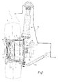
- Number 1 in the accompanying drawings indicates a power-driven wheel, for a military vehicle, substantially comprising a hub 2; a tyre 3 (( Figures 1 and 2 ) surrounding and angularly integral with hub 2; and an electric motor 4 (only shown schematically in Figures 1 , 2 , 4 ) connected functionally to hub 2.
- wheel 1 has, and rotates about, an axis A; and hub 2 is tubular.
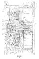
- Motor 4 is housed in a casing 5, which, as described below, is axially fixed with respect to hub 2, and retains motor 4 axially in a predetermined position with respect to wheel 1.
- casing 5 comprises a housing 6 for housing motor 4, and which defines, at opposite axial ends, a retaining surface 11 facing inwards of hub 2, and an opening 14 projecting outwards of hub 2.
- casing 5 also comprises an end member 8 engaging opening 14 to grip motor 4 axially against retaining surface 11 and hold it in a predetermined position inside wheel 1.
- Motor 4 is an axial-flow type, and has an axis coincident, in use, with axis A.
- Motor 4 substantially comprises two coils 9, through which alternating electric current flows in use; a number of permanent magnets 18 generating axial flux on coils 9 and rotating with respect to coils 9; and a shaft 7 angularly integral with magnets 18 and connected functionally to hub 2.
- Motor 4 also comprises a supporting body 10, which is formed in two axially spaced parts, is housed radially loosely inside housing 6, and is gripped axially between surface 11 of housing 6 and member 8.
- Coils 9, magnets 18, and shaft 7 are housed inside body 10.
- Coils 9 and body 10 are glued to one another.
- Coils 9 are offset axially, and each wound about a respective annular core of ferromagnetic material.
- Shaft 7 has an axial end 12 connected functionally to hub 2; and a second axial end 13, opposite end 12, connected functionally to a brake 15 (only shown in Figures 1 to 3 ) projecting axially from wheel 1. More specifically, brake 15 comprises, in known manner, a disk 16, and a shoe 17 7 (only shown in Figure 1 ) which cooperates frictionally with disk 16 to brake wheel 1.
- Magnets 18 are arranged to form four axially spaced magnetizing units 19.
- Units 19 are annular, and extend radially with respect to axis A.
- Each unit 19 is defined by an annular sequence of magnets 18 arranged with alternating polarities.
- Each coil 9 is interposed axially between two units 19, so that its axial ends each face a respective unit 19.
- Each coil 9 is thus coupled magnetically to the units 19 between which it is interposed.
- each unit 19 is carried by a flange 20 angularly integral with a flange 21 fitted to shaft 7.
- Flanges 20 are located radially outwards of flanges 21.
- Shaft 7 is advantageously housed at least partly inside hub 2, and wheel 1 comprises an epicyclic reducer 22 ( Figure 4 ) interposed functionally between hub 2 and shaft 7.
- Reducer 22 comprises a sun gear 23 connected angularly to shaft 7; a ring gear 24 fixed to surface 11 of housing 6; three planet gears (only one shown in Figure 4 ) connected angularly to ring gear 24 and sun gear 23; and a planet carrier 26 connected angularly to hub 2 and planet gears 25.
- shaft 7 and sun gear 23 have respective matching, meshing splines 27, 28, and are therefore connected in angularly fixed, axially free manner.
- Planet gears 25 are equally spaced angularly, and each extend along a respective axis B parallel to and offset with respect to axis A.
- Each planet gear 25 has teeth 30 which, at opposite radial ends, mesh with teeth 29 on sun gear 23, and with teeth 31 on ring gear 24.
- teeth 30, 29 mesh in a position radially inwards with respect to the meshing position of teeth 30, 31.
- Planet carrier 26 comprises a main body 32, of axis A; and three pins 33 carried by main body 32 and extending along respective axes B.
- main body 32 surrounds sun gear 23, and comprises teeth 37 meshing with teeth 38 of a flange 40 integral with hub 2.
- Main body 32 is axially hollow, and houses, radially loosely, the end of sun gear 23 opposite spline 27.
- main body 32 is defined by two axially opposite annular flanges extending perpendicular to axis A.
- Each pin 33 is housed inside a hole 34 defined by a respective planet gear 25. More specifically, each pin 33 is supported inside respective hole 34 by a bearing 35, so as to hinge planet carrier 26 to planet gears 25 about respective axes B.
- Flange 40 is supported inside ring gear 24 by a bearing 41.
- Reducer 22 comprises two axially spaced bearings 42, each interposed radially between sun gear 23 and a respective flange of main body 32 of planet carrier 26.
- member 8 and brake 15 are axially hollow to permit insertion of a portion of shaft 7 adjacent to end 13.
- end 13 is housed in a through seat formed coaxially in brake 15, and is fixed to brake 15 to make shaft 7 and brake 15 angularly integral.
- Member 8 is fitted releasably to housing 6 by means of screws.
- member 8 is fitted to housing 6 by a radial end opposite axis A.
- a suspension 43 connects wheel 1 to a frame 45 (shown schematically by a broken line in Figure 1 ) of the military vehicle.
- Suspension 43 comprises two arms 44, both connected to housing 6 of casing 5 on opposite sides of axis A.
- Arms 44 and frame 45 are arranged with respect to housing 6 so that, when member 8 is removed from housing 6, motor 4 can be inserted through opening 14 without interfering with suspension 43.
- Body 10 defines a cooling circuit 36 ( Figure 3 ) located radially outwards of coils 9 and defined by a number of helical cavities 39, along which coolant flows through body 10 to cool motor 4.
- Wheel 1 also comprises fluidic connecting means 50 ( Figures 3 , 4 ), which connect an inner chamber 49 of tyre 3 fluidically to the outside to permit air circulation by which to inflate tyre 3.
- Chamber 49 is connected fluidically to the inner tube of tyre 3 in a manner not shown.
- fluidic connecting means 50 comprise a conduit 51 ( Figure 3 ) extending coaxially through shaft 7; and a conduit 52 ( Figure 4 ) extending through sun gear 23 and connected in fluidtight manner to conduit 51.
- Fluidic connecting means 50 also comprise a conduit 54 ( Figure 4 ), which is connected in fluidtight manner to conduit 52, opens inside chamber 49, and is formed in a pin 55 angularly integral with planet carrier 26.
- pin 55 extends axially between chamber 49 and sun gear 23, and comprises a portion 62 engaging an axial hole in flange 40; and a portion 63 axially opposite portion 62 and engaging an end portion of conduit 52 facing chamber 49.
- Portion 62 is radially larger than portion 63.
- conduit 51 has opposite axial ends 56, 57 connected fluidically to the outside and to an end 58 of conduit 52 respectively.
- Conduit 51 also comprises opposite axial end portions; and an intermediate portion larger radially than the axial end portions.
- Conduit 52 has an axial end 59 opposite end 58 and housing portion 63 of pin 55.
- Conduit 52 increases in size radially from end 58 to end 59.
- Conduit 54 has an axial end 60 defined by portion 63 and housed inside conduit 52; and an end 61 defined by portion 62 and facing inwards of chamber 49.
- motor 4 is housed inside casing 5 and gripped axially between surface 11 of housing 6 and member 8.
- Alternating electric current flows through coils 9, which are swept by the magnetic flux, parallel to axis A, generated by magnets 18 of units 19.
- the magnetic flux generated by units 19 generates a torque, of axis A, on coils 9 in known manner.
- Coils 9 in turn exert on units 19 a torque of equal intensity and also directed along axis A.
- Coils 9 being angularly fixed with respect to axis A, units 19, by reaction, rotate about axis A, thus integrally rotating shaft 7.
- Shaft 7 integrally rotates sun gear 23 of reducer 22, by virtue of the coupling defined by splines 27, 28.
- Rotation of sun gear 23 rotates planet gears 25 in known manner about respective axes B, and revolves planet gears 25 about axis A, while ring gear 24 remains fixed.
- Rotation of planet gears 25 in turn rotates planet carrier 26 and hub 2 about axis A.
- air can be fed into chamber 49 by means of fluidic connecting means 50 to inflate the inner tube of tyre 3.
- Motor 4 is removed from wheel 1 by simply removing member 8 from housing 6 and withdrawing motor 4 through opening 14 of housing 6.
- wheel 1 generates considerable power by employing an axial-flow motor 4, and is axially compact, by virtue of shaft 7 being housed at least partly inside hub 2, and hub 2 and shaft 7 being connected by reducer 22.
- reducer 22 Being epicyclic, reducer 22, in fact, provides for considerable speed reduction and torque increase, while also being axially compact.
- reducer 22 allows wheel 1 to overcome steep slopes and/or to travel easily over muddy and/or marshy terrain.
- wheel 1 is safeguarded against damage, in the event of attack of the military vehicle, by virtue of most of shaft 7 being housed inside hub 2.
- cooling circuit 36 can be replaced without interfering with either suspension 43 or frame 45.
- Motor 4 can be removed from and inserted into housing 6 extremely easily, by virtue of arms 44 of suspension 43 being connected solely to housing 6.
- Member 8 can therefore be removed from housing 6 without interfering with suspension 43, thus enabling troublefree removal of motor 4 through opening 14.
- fluidic connecting means 50 provide for troublefree inflation of tyre 3.
- Tyre 3 in fact, can be inflated by connecting the compressed-air source to end 56 of conduit 51, without interfering with either hub 2 or motor 4.
- coils 9 may be integral with shaft 7, and magnets 18 integral with body 10.
Landscapes
- Engineering & Computer Science (AREA)
- Chemical & Material Sciences (AREA)
- Combustion & Propulsion (AREA)
- Transportation (AREA)
- Mechanical Engineering (AREA)
- Arrangement Or Mounting Of Propulsion Units For Vehicles (AREA)
- Auxiliary Drives, Propulsion Controls, And Safety Devices (AREA)
- Braking Arrangements (AREA)
- Inorganic Insulating Materials (AREA)
- Vehicle Body Suspensions (AREA)
- Body Structure For Vehicles (AREA)
Priority Applications (8)
| Application Number | Priority Date | Filing Date | Title |
|---|---|---|---|
| DK10161216.6T DK2206620T3 (da) | 2006-12-15 | 2007-11-02 | Motordrevet hjul til et militærkøretøj |
| DK10161215.8T DK2204300T3 (da) | 2006-12-15 | 2007-11-02 | Kraft-drevet hjul til et militærkøretøj |
| EP10161216A EP2206620B1 (fr) | 2006-12-15 | 2007-11-02 | Roue à moteur pour véhicule militaire |
| EP10161215A EP2204300B1 (fr) | 2006-12-15 | 2007-11-02 | Roue à moteur pour véhicule militaire |
| PL10161216T PL2206620T3 (pl) | 2006-12-15 | 2007-11-02 | Napędzane silnikiem koło dla pojazdu wojskowego |
| PL07119871T PL1932706T3 (pl) | 2006-12-15 | 2007-11-02 | Koło o napędzie silnikowym dla pojazdu wojskowego |
| SI200730556T SI1932706T1 (sl) | 2006-12-15 | 2007-11-02 | Kolo na motorni pogon za vojaško vozilo |
| PL10161215T PL2204300T3 (pl) | 2006-12-15 | 2007-11-02 | Koło o napędzie silnikowym dla pojazdu wojskowego |
Applications Claiming Priority (1)
| Application Number | Priority Date | Filing Date | Title |
|---|---|---|---|
| IT000894A ITTO20060894A1 (it) | 2006-12-15 | 2006-12-15 | Ruota motorizzata per un veicolo militare |
Related Child Applications (2)
| Application Number | Title | Priority Date | Filing Date |
|---|---|---|---|
| EP10161215.8 Division-Into | 2010-04-27 | ||
| EP10161216.6 Division-Into | 2010-04-27 |
Publications (3)
| Publication Number | Publication Date |
|---|---|
| EP1932706A2 true EP1932706A2 (fr) | 2008-06-18 |
| EP1932706A3 EP1932706A3 (fr) | 2009-06-03 |
| EP1932706B1 EP1932706B1 (fr) | 2011-01-05 |
Family
ID=38920891
Family Applications (3)
| Application Number | Title | Priority Date | Filing Date |
|---|---|---|---|
| EP07119871A Active EP1932706B1 (fr) | 2006-12-15 | 2007-11-02 | Roue à moteur pour véhicule militaire |
| EP10161215A Active EP2204300B1 (fr) | 2006-12-15 | 2007-11-02 | Roue à moteur pour véhicule militaire |
| EP10161216A Active EP2206620B1 (fr) | 2006-12-15 | 2007-11-02 | Roue à moteur pour véhicule militaire |
Family Applications After (2)
| Application Number | Title | Priority Date | Filing Date |
|---|---|---|---|
| EP10161215A Active EP2204300B1 (fr) | 2006-12-15 | 2007-11-02 | Roue à moteur pour véhicule militaire |
| EP10161216A Active EP2206620B1 (fr) | 2006-12-15 | 2007-11-02 | Roue à moteur pour véhicule militaire |
Country Status (12)
| Country | Link |
|---|---|
| US (3) | US8550197B2 (fr) |
| EP (3) | EP1932706B1 (fr) |
| AT (3) | ATE494174T1 (fr) |
| CA (3) | CA2848265A1 (fr) |
| DE (1) | DE602007011717D1 (fr) |
| DK (3) | DK1932706T3 (fr) |
| ES (3) | ES2369247T3 (fr) |
| IL (3) | IL210702A (fr) |
| IT (1) | ITTO20060894A1 (fr) |
| PL (3) | PL1932706T3 (fr) |
| PT (2) | PT2206620E (fr) |
| SI (3) | SI1932706T1 (fr) |
Cited By (7)
| Publication number | Priority date | Publication date | Assignee | Title |
|---|---|---|---|---|
| JP2010221934A (ja) * | 2009-03-25 | 2010-10-07 | Aisin Seiki Co Ltd | インホイールモータユニット |
| NL2005713C2 (nl) * | 2010-11-18 | 2012-05-22 | Gemert Mobile Systems B V Van | Wielophanging en voertuig voorzien van een dergelijke wielophanging. |
| WO2012123174A2 (fr) * | 2011-03-16 | 2012-09-20 | Zf Friedrichshafen Ag | Dispositif d'entraînement pour entraîner une roue d'un essieu mac pherson de véhicule électrique |
| CN102792563A (zh) * | 2011-03-07 | 2012-11-21 | Ntn株式会社 | 电动汽车用驱动装置 |
| EP2684723A1 (fr) * | 2011-03-07 | 2014-01-15 | NTN Corporation | Dispositif d'entraînement pour véhicule électrique |
| EP3807977A4 (fr) * | 2018-06-15 | 2022-06-29 | Indigo Technologies, Inc. | Moteur à flux axial étanche à refroidissement intégré |
| US11524568B2 (en) * | 2017-07-14 | 2022-12-13 | Robert Bosch Gmbh | Electric vehicle and the wheel assembly thereof |
Families Citing this family (27)
| Publication number | Priority date | Publication date | Assignee | Title |
|---|---|---|---|---|
| DE102008001791B4 (de) * | 2008-05-15 | 2011-09-29 | Zf Friedrichshafen Ag | Getriebeeinheit mit translatorischem Freiheitsgrad |
| KR101269928B1 (ko) * | 2008-11-10 | 2013-05-31 | 주식회사 만도 | 휠 내장형 모터를 갖춘 차량 |
| US20120001502A1 (en) * | 2010-07-01 | 2012-01-05 | Yee-Chun Lee | Multi-unit Modular Stackable Switched Reluctance Motor System with Parallely Excited Low Reluctance Circumferential Magnetic Flux loops for High Torque Density Generation |
| US8617019B2 (en) * | 2010-11-19 | 2013-12-31 | Honeywell International Inc. | Aircraft electric taxi system with friction actuated, bi-directional clutch |
| US8747271B2 (en) * | 2011-03-12 | 2014-06-10 | General Electric Company | Wheel rim assembly and method |
| ITUD20120001A1 (it) * | 2012-01-03 | 2013-07-04 | Pmp Pro Mec S P A | "motoriduttore con freno e inverter integrati per trasmissione diretta alla ruota di veicolo a trazione elettrica" |
| US9308811B2 (en) * | 2012-05-10 | 2016-04-12 | Goldhofer Aktiengesellschaft | Drive device for motor vehicles |
| DE102013216925A1 (de) * | 2012-09-21 | 2014-03-27 | Ford Global Technologies, Llc | Radlagereinheit und Kraftfahrzeug mit Radlagereinheit |
| US9725163B2 (en) * | 2012-12-24 | 2017-08-08 | Borealis Technical Limited | Electric power connector for aircraft drive wheel drive system |
| US20150292601A1 (en) * | 2013-10-11 | 2015-10-15 | Delbert Tesar | Standardized gear train modules for multi-speed hub drive wheels |
| JP6313610B2 (ja) * | 2014-02-27 | 2018-04-18 | Ntn株式会社 | インホイールモータ駆動装置とダンパとの連結構造およびこの連結構造を備えるサスペンション装置 |
| CN103863102A (zh) * | 2014-03-13 | 2014-06-18 | 索特传动设备有限公司 | 轮边减速机、驱动桥及车辆 |
| JP6670571B2 (ja) * | 2015-09-28 | 2020-03-25 | Ntn株式会社 | インホイールモータ駆動装置とストラット式サスペンション装置の連結構造 |
| JP6853622B2 (ja) * | 2015-09-29 | 2021-03-31 | Ntn株式会社 | インホイールモータ駆動装置、およびインホイールモータ駆動装置とサスペンション装置の連結構造 |
| JP6823417B2 (ja) * | 2016-09-30 | 2021-02-03 | Ntn株式会社 | インホイールモータ駆動装置 |
| US11038396B2 (en) * | 2018-11-30 | 2021-06-15 | Arvinmeritor Technology, Llc | Axle assembly having an electric motor module and method of assembly |
| BR102019000446A2 (pt) * | 2019-01-09 | 2020-07-28 | CNH Industrial Brasil Ltda. | redutor epicíclico para um cubo de roda e veículo |
| CN110481305B (zh) * | 2019-07-17 | 2021-04-27 | 西安交通大学 | 对称布置盘式电机差动轮系复合驱动的汽车轮毂电机 |
| US11446960B2 (en) * | 2019-08-27 | 2022-09-20 | Toyota Motor Engineering & Manufacturing North America, Inc. | Modular axle and motive wheel system for a vehicle |
| US11390163B2 (en) * | 2019-08-27 | 2022-07-19 | Toyota Motor Engineering & Manufacturing North America, Inc. | Variable wheel drive electric vehicle comprising selectively attachable and detachable electric hub motors and method of using the same |
| CN112572374B (zh) * | 2019-09-30 | 2022-12-30 | 新疆大道防务装备有限公司 | 一种轮边减速器总成及车轮总成 |
| US11479107B2 (en) | 2019-09-30 | 2022-10-25 | Toyota Motor Engineering & Manufacturing North America, Inc. | Selectively attachable and detachable axial hub motor |
| US11453296B2 (en) | 2019-09-30 | 2022-09-27 | Toyota Motor Engineering & Manufacturing North America, Inc. | Systems and methods for improving propulsion of a vehicle using selectively attachable hub motors |
| US11529862B2 (en) | 2019-09-30 | 2022-12-20 | Toyota Motor Engineering & Manufacturing North America, Inc. | Systems and methods for improving propulsion of a vehicle using selectively attachable hub motors and rotatable axles |
| BR102019021704A2 (pt) * | 2019-10-16 | 2021-04-20 | CNH Industrial Brasil Ltda. | cubo de roda para montar uma roda a um eixo de um veículo de trabalho |
| US11485215B1 (en) * | 2021-12-09 | 2022-11-01 | Workhorse Group Inc. | Land vehicles incorporating electric motors and methods therefor |
| US20240051404A1 (en) * | 2022-08-11 | 2024-02-15 | Karma Automotive Llc | Rotor-Wheeled Motor Assembly With Integrated Inverter and Cooling Device for Electric Vehicles |
Family Cites Families (40)
| Publication number | Priority date | Publication date | Assignee | Title |
|---|---|---|---|---|
| DE2842076C2 (de) * | 1978-09-27 | 1984-09-06 | Siemens AG, 1000 Berlin und 8000 München | Einzelradantrieb für Fahrzeuge |
| US4389586A (en) * | 1982-02-22 | 1983-06-21 | General Electric Company | Electric wheel with removable motor |
| US4799464A (en) | 1983-03-03 | 1989-01-24 | Toledo Stamping & Manufacturing Company | Boat-type rocker arm assembly |
| CA1279582C (fr) * | 1986-01-29 | 1991-01-29 | Katsuhiko Iijima | Entrainement electrique de roues |
| US5087229A (en) * | 1991-05-06 | 1992-02-11 | General Motors Corporation | Independently suspended steerable motor wheel apparatus |
| FR2679842A1 (fr) * | 1991-07-29 | 1993-02-05 | Shm Management Services Ag | Module de roulement moteur, notamment pour vehicule automobile. |
| US5587698A (en) * | 1992-02-05 | 1996-12-24 | Genna; Robert A. | Automatic tire pressure control system for a vehicle |
| US5382854A (en) * | 1992-07-29 | 1995-01-17 | Kabushikikaisha Equos Research | Electrical motor drive apparatus with planetary gearing |
| US5363937A (en) | 1992-10-19 | 1994-11-15 | Lmc Operating Corp. | Battery operated tracked vehicle |
| FI945923A (fi) * | 1994-04-08 | 1995-10-09 | Toivo Johannes Pitkaenen | Vapaasti keinuva pyörä |
| US5538062A (en) * | 1994-08-12 | 1996-07-23 | Marks-Rms, Inc. | Pnuematic tire inflation system |
| DE19732637C5 (de) * | 1997-07-29 | 2006-09-14 | Daimlerchrysler Ag | Elektrischer Antrieb für eine Radnabe |
| JP3939862B2 (ja) * | 1998-08-18 | 2007-07-04 | ヤマハ発動機株式会社 | 電動自転車用モータ駆動ユニット |
| US6046518A (en) * | 1999-01-21 | 2000-04-04 | Williams; Malcolm R. | Axial gap electrical machine |
| US6145559A (en) * | 1999-09-03 | 2000-11-14 | Accessio, Ltd. | Axle and hub assembly for automatic tire inflation pressurization system |
| IT1313889B1 (it) * | 1999-12-17 | 2002-09-24 | S O M S P A | Motoruota per l'azionamento della ruota motrice di un veicoloindustriale e simili. |
| US6325123B1 (en) * | 1999-12-23 | 2001-12-04 | Dana Corporation | Tire inflation system for a steering knuckle wheel end |
| JP3440082B2 (ja) | 2001-02-19 | 2003-08-25 | 科学技術振興事業団 | 電気自動車用インホイールモーター |
| DE10121372A1 (de) | 2001-05-02 | 2002-11-07 | Krauss Maffei Wegmann Gmbh & C | Allradangetriebenes Kraftfahrzeug, insbesondere militärisches Kraftfahrzeug, mit dieselelektrischer Antriebsvorrichtung |
| US7013931B2 (en) * | 2001-05-31 | 2006-03-21 | Pressurite (Pty) Ltd. | Device for inflating vehicle tires |
| US6768932B2 (en) * | 2001-12-07 | 2004-07-27 | General Motors Corporation | Wheel motor system |
| ITTO20020189A1 (it) * | 2002-03-06 | 2003-09-08 | Skf Ind Spa | Dispositivo per l'alimentazione di aria compressa al pneumatico dellaruota di un veicolo attraverso il mozzo. |
| US6922004B2 (en) * | 2002-04-05 | 2005-07-26 | The Timken Company | Axial flux motor assembly |
| US7520354B2 (en) * | 2002-05-02 | 2009-04-21 | Oshkosh Truck Corporation | Hybrid vehicle with combustion engine/electric motor drive |
| GB2389827B (en) * | 2002-06-18 | 2005-12-14 | Magnetic Systems Technology Lt | Hub drive system |
| JP4348941B2 (ja) * | 2002-11-26 | 2009-10-21 | 日産自動車株式会社 | 車輪用回転電機の取付構造 |
| US7150340B2 (en) * | 2003-02-21 | 2006-12-19 | Lockheed Martin Corporation | Hub drive and method of using same |
| US7262536B2 (en) | 2003-08-11 | 2007-08-28 | General Motors Corporation | Gearless wheel motor drive system |
| DE10338659A1 (de) | 2003-08-22 | 2005-03-17 | Magnet-Motor Gesellschaft Für Magnetmotorische Technik Mbh | Elektrische Antriebseinheit für ein Kraftfahrzeug |
| DE10339433A1 (de) | 2003-08-27 | 2005-03-24 | Linde Ag | Selbsttragendes Antriebsmodul |
| JP2005081872A (ja) * | 2003-09-04 | 2005-03-31 | Toyota Motor Corp | インホイールモータ |
| DE102004004617A1 (de) | 2004-01-29 | 2005-09-08 | Magnet-Motor Gesellschaft Für Magnetmotorische Technik Mbh | Elektrische Antriebseinheit für ein Kraftfahrzeug |
| JP2005231564A (ja) * | 2004-02-23 | 2005-09-02 | Ntn Corp | 電動式車輪駆動装置 |
| US8245746B2 (en) * | 2004-07-21 | 2012-08-21 | Arvinmeritor Technology, Llc | Tire inflation system with pressure limiter |
| DE602004008288T2 (de) * | 2004-09-29 | 2008-05-15 | Nexxtdrive Ltd. | Nabe mit einem Antrieb mit veränderlicher Übersetzung |
| US7420301B2 (en) * | 2004-10-04 | 2008-09-02 | Axletech International Ip Holdings, Llc | Wheel assembly with integral electric motor |
| US7886858B2 (en) * | 2005-01-13 | 2011-02-15 | The Timken Company | High reduction ratio electric hub drive |
| DE602005008450D1 (de) * | 2005-11-17 | 2008-09-04 | Skf Ab | Dichteinrichtung für Lagerungen zum Zuführen von Druckluft in Fahrzeugreifen |
| JP3960553B1 (ja) * | 2006-03-31 | 2007-08-15 | 本田技研工業株式会社 | インホイールモータ車のホイール回転装置 |
| JP4758852B2 (ja) * | 2006-08-29 | 2011-08-31 | 本田技研工業株式会社 | ホイール回転装置のブレーキ構造 |
-
2006
- 2006-12-15 IT IT000894A patent/ITTO20060894A1/it unknown
-
2007
- 2007-11-01 IL IL210702A patent/IL210702A/en active IP Right Grant
- 2007-11-01 CA CA2848265A patent/CA2848265A1/fr not_active Abandoned
- 2007-11-01 US US11/933,597 patent/US8550197B2/en not_active Expired - Fee Related
- 2007-11-01 CA CA2848266A patent/CA2848266A1/fr not_active Abandoned
- 2007-11-01 IL IL187093A patent/IL187093A/en active IP Right Grant
- 2007-11-01 CA CA 2609123 patent/CA2609123C/fr not_active Expired - Fee Related
- 2007-11-01 IL IL210701A patent/IL210701A/en active IP Right Grant
- 2007-11-02 PT PT10161216T patent/PT2206620E/pt unknown
- 2007-11-02 SI SI200730556T patent/SI1932706T1/sl unknown
- 2007-11-02 DE DE602007011717T patent/DE602007011717D1/de active Active
- 2007-11-02 ES ES10161215T patent/ES2369247T3/es active Active
- 2007-11-02 DK DK07119871.7T patent/DK1932706T3/da active
- 2007-11-02 PL PL07119871T patent/PL1932706T3/pl unknown
- 2007-11-02 EP EP07119871A patent/EP1932706B1/fr active Active
- 2007-11-02 SI SI200730747T patent/SI2206620T1/sl unknown
- 2007-11-02 PT PT10161215T patent/PT2204300E/pt unknown
- 2007-11-02 EP EP10161215A patent/EP2204300B1/fr active Active
- 2007-11-02 SI SI200730710T patent/SI2204300T1/sl unknown
- 2007-11-02 PL PL10161215T patent/PL2204300T3/pl unknown
- 2007-11-02 EP EP10161216A patent/EP2206620B1/fr active Active
- 2007-11-02 PL PL10161216T patent/PL2206620T3/pl unknown
- 2007-11-02 ES ES07119871T patent/ES2358221T3/es active Active
- 2007-11-02 AT AT07119871T patent/ATE494174T1/de active
- 2007-11-02 AT AT10161216T patent/ATE518687T1/de active
- 2007-11-02 ES ES10161216T patent/ES2370112T3/es active Active
- 2007-11-02 DK DK10161215.8T patent/DK2204300T3/da active
- 2007-11-02 DK DK10161216.6T patent/DK2206620T3/da active
- 2007-11-02 AT AT10161215T patent/ATE518686T1/de active
-
2011
- 2011-10-06 US US13/267,139 patent/US8342612B2/en active Active
- 2011-10-06 US US13/267,647 patent/US8353376B2/en active Active
Non-Patent Citations (1)
| Title |
|---|
| None |
Cited By (18)
| Publication number | Priority date | Publication date | Assignee | Title |
|---|---|---|---|---|
| US8590649B2 (en) | 2009-03-25 | 2013-11-26 | Aisin Seiki Kabushiki Kaisha | In-wheel motor unit |
| EP2412554A1 (fr) * | 2009-03-25 | 2012-02-01 | Aisin Seiki Kabushiki Kaisha | Unité motorisée dans les roues |
| EP2412554A4 (fr) * | 2009-03-25 | 2012-09-05 | Aisin Seiki | Unité motorisée dans les roues |
| JP2010221934A (ja) * | 2009-03-25 | 2010-10-07 | Aisin Seiki Co Ltd | インホイールモータユニット |
| NL2005713C2 (nl) * | 2010-11-18 | 2012-05-22 | Gemert Mobile Systems B V Van | Wielophanging en voertuig voorzien van een dergelijke wielophanging. |
| EP2685609A4 (fr) * | 2011-03-07 | 2015-04-08 | Ntn Toyo Bearing Co Ltd | Dispositif d'entraînement pour véhicule électrique |
| CN102792563A (zh) * | 2011-03-07 | 2012-11-21 | Ntn株式会社 | 电动汽车用驱动装置 |
| EP2684723A1 (fr) * | 2011-03-07 | 2014-01-15 | NTN Corporation | Dispositif d'entraînement pour véhicule électrique |
| EP2685609A1 (fr) * | 2011-03-07 | 2014-01-15 | NTN Corporation | Dispositif d'entraînement pour véhicule électrique |
| EP2684723A4 (fr) * | 2011-03-07 | 2014-10-01 | Ntn Toyo Bearing Co Ltd | Dispositif d'entraînement pour véhicule électrique |
| US8932166B2 (en) | 2011-03-07 | 2015-01-13 | Ntn Corporation | Drive device for electric vehicle |
| US9735648B2 (en) | 2011-03-07 | 2017-08-15 | Ntn Corporation | Drive device for electric vehicle |
| CN102792563B (zh) * | 2011-03-07 | 2019-11-01 | Ntn株式会社 | 电动汽车用驱动装置 |
| WO2012123174A3 (fr) * | 2011-03-16 | 2013-03-28 | Zf Friedrichshafen Ag | Dispositif d'entraînement pour entraîner une roue d'un essieu mac pherson de véhicule électrique |
| WO2012123174A2 (fr) * | 2011-03-16 | 2012-09-20 | Zf Friedrichshafen Ag | Dispositif d'entraînement pour entraîner une roue d'un essieu mac pherson de véhicule électrique |
| US11524568B2 (en) * | 2017-07-14 | 2022-12-13 | Robert Bosch Gmbh | Electric vehicle and the wheel assembly thereof |
| EP3807977A4 (fr) * | 2018-06-15 | 2022-06-29 | Indigo Technologies, Inc. | Moteur à flux axial étanche à refroidissement intégré |
| US11411450B2 (en) | 2018-06-15 | 2022-08-09 | Indigo Technologies, Inc. | Sealed axial flux motor with integrated cooling |
Also Published As
Similar Documents
| Publication | Publication Date | Title |
|---|---|---|
| EP2204300B1 (fr) | Roue à moteur pour véhicule militaire | |
| CN102951010B (zh) | 具有制动器的车轮内电动机 | |
| US8733483B2 (en) | In-wheel motor drive assembly | |
| WO2002094603A3 (fr) | Moteur dans un systeme d'entrainement electrique des roues | |
| JP4689949B2 (ja) | インホイールモータ | |
| US20190128393A1 (en) | Hybrid module including electric motor on front differential | |
| JP3337279B2 (ja) | ホイールモータ | |
| JP2008215550A (ja) | 歯車変速機構及び車輪駆動装置 | |
| CN110345248B (zh) | 车辆的停车机构 | |
| KR100769877B1 (ko) | 일체형 동력전달축을 구비한 전동기 | |
| CN116670987A (zh) | 用于驱动轮辋的电动盘式马达 | |
| CN111717020A (zh) | 电动汽车轮毂电机驱动制动系统 | |
| JP5235824B2 (ja) | モータ付デファレンシャル装置 | |
| CN109802521A (zh) | 一种包含控制器和水冷系统自带减速齿轮轮毂电机 | |
| JP2011047501A (ja) | モータ付デファレンシャル装置 | |
| CN117601641A (zh) | 一种大扭矩非断开式驱动桥轮毂电机 | |
| KR20240079165A (ko) | 동력 전달 장치 | |
| JP2004058700A (ja) | 電気自動車用駆動装置 | |
| JP2011046350A (ja) | モータ付デファレンシャル装置 | |
| JP2006111049A (ja) | 駆動装置および車輪構造 |
Legal Events
| Date | Code | Title | Description |
|---|---|---|---|
| PUAI | Public reference made under article 153(3) epc to a published international application that has entered the european phase |
Free format text: ORIGINAL CODE: 0009012 |
|
| AK | Designated contracting states |
Kind code of ref document: A2 Designated state(s): AT BE BG CH CY CZ DE DK EE ES FI FR GB GR HU IE IS IT LI LT LU LV MC MT NL PL PT RO SE SI SK TR |
|
| AX | Request for extension of the european patent |
Extension state: AL BA HR MK RS |
|
| RIN1 | Information on inventor provided before grant (corrected) |
Inventor name: FRANCESCHI, GIULIANO Inventor name: SGHERRI, ROBERTO |
|
| PUAL | Search report despatched |
Free format text: ORIGINAL CODE: 0009013 |
|
| AK | Designated contracting states |
Kind code of ref document: A3 Designated state(s): AT BE BG CH CY CZ DE DK EE ES FI FR GB GR HU IE IS IT LI LT LU LV MC MT NL PL PT RO SE SI SK TR |
|
| AX | Request for extension of the european patent |
Extension state: AL BA HR MK RS |
|
| 17P | Request for examination filed |
Effective date: 20091203 |
|
| 17Q | First examination report despatched |
Effective date: 20100108 |
|
| AKX | Designation fees paid |
Designated state(s): AT BE BG CH CY CZ DE DK EE ES FI FR GB GR HU IE IS IT LI LT LU LV MC MT NL PL PT RO SE SI SK TR |
|
| GRAP | Despatch of communication of intention to grant a patent |
Free format text: ORIGINAL CODE: EPIDOSNIGR1 |
|
| GRAS | Grant fee paid |
Free format text: ORIGINAL CODE: EPIDOSNIGR3 |
|
| GRAA | (expected) grant |
Free format text: ORIGINAL CODE: 0009210 |
|
| AK | Designated contracting states |
Kind code of ref document: B1 Designated state(s): AT BE BG CH CY CZ DE DK EE ES FI FR GB GR HU IE IS IT LI LT LU LV MC MT NL PL PT RO SE SI SK TR |
|
| REG | Reference to a national code |
Ref country code: GB Ref legal event code: FG4D |
|
| REG | Reference to a national code |
Ref country code: CH Ref legal event code: EP |
|
| REG | Reference to a national code |
Ref country code: IE Ref legal event code: FG4D |
|
| REF | Corresponds to: |
Ref document number: 602007011717 Country of ref document: DE Date of ref document: 20110217 Kind code of ref document: P |
|
| REG | Reference to a national code |
Ref country code: DE Ref legal event code: R096 Ref document number: 602007011717 Country of ref document: DE Effective date: 20110217 |
|
| REG | Reference to a national code |
Ref country code: CH Ref legal event code: NV Representative=s name: MOINAS & SAVOYE SA |
|
| REG | Reference to a national code |
Ref country code: DK Ref legal event code: T3 |
|
| REG | Reference to a national code |
Ref country code: NL Ref legal event code: T3 |
|
| REG | Reference to a national code |
Ref country code: SE Ref legal event code: TRGR |
|
| REG | Reference to a national code |
Ref country code: ES Ref legal event code: FG2A Ref document number: 2358221 Country of ref document: ES Kind code of ref document: T3 Effective date: 20110425 |
|
| REG | Reference to a national code |
Ref country code: PL Ref legal event code: T3 |
|
| LTIE | Lt: invalidation of european patent or patent extension |
Effective date: 20110105 |
|
| PG25 | Lapsed in a contracting state [announced via postgrant information from national office to epo] |
Ref country code: IS Free format text: LAPSE BECAUSE OF FAILURE TO SUBMIT A TRANSLATION OF THE DESCRIPTION OR TO PAY THE FEE WITHIN THE PRESCRIBED TIME-LIMIT Effective date: 20110505 Ref country code: LT Free format text: LAPSE BECAUSE OF FAILURE TO SUBMIT A TRANSLATION OF THE DESCRIPTION OR TO PAY THE FEE WITHIN THE PRESCRIBED TIME-LIMIT Effective date: 20110105 Ref country code: GR Free format text: LAPSE BECAUSE OF FAILURE TO SUBMIT A TRANSLATION OF THE DESCRIPTION OR TO PAY THE FEE WITHIN THE PRESCRIBED TIME-LIMIT Effective date: 20110406 Ref country code: LV Free format text: LAPSE BECAUSE OF FAILURE TO SUBMIT A TRANSLATION OF THE DESCRIPTION OR TO PAY THE FEE WITHIN THE PRESCRIBED TIME-LIMIT Effective date: 20110105 |
|
| PG25 | Lapsed in a contracting state [announced via postgrant information from national office to epo] |
Ref country code: FI Free format text: LAPSE BECAUSE OF FAILURE TO SUBMIT A TRANSLATION OF THE DESCRIPTION OR TO PAY THE FEE WITHIN THE PRESCRIBED TIME-LIMIT Effective date: 20110105 Ref country code: CY Free format text: LAPSE BECAUSE OF FAILURE TO SUBMIT A TRANSLATION OF THE DESCRIPTION OR TO PAY THE FEE WITHIN THE PRESCRIBED TIME-LIMIT Effective date: 20110105 |
|
| PG25 | Lapsed in a contracting state [announced via postgrant information from national office to epo] |
Ref country code: EE Free format text: LAPSE BECAUSE OF FAILURE TO SUBMIT A TRANSLATION OF THE DESCRIPTION OR TO PAY THE FEE WITHIN THE PRESCRIBED TIME-LIMIT Effective date: 20110105 |
|
| PLBE | No opposition filed within time limit |
Free format text: ORIGINAL CODE: 0009261 |
|
| STAA | Information on the status of an ep patent application or granted ep patent |
Free format text: STATUS: NO OPPOSITION FILED WITHIN TIME LIMIT |
|
| PG25 | Lapsed in a contracting state [announced via postgrant information from national office to epo] |
Ref country code: RO Free format text: LAPSE BECAUSE OF FAILURE TO SUBMIT A TRANSLATION OF THE DESCRIPTION OR TO PAY THE FEE WITHIN THE PRESCRIBED TIME-LIMIT Effective date: 20110105 Ref country code: SK Free format text: LAPSE BECAUSE OF FAILURE TO SUBMIT A TRANSLATION OF THE DESCRIPTION OR TO PAY THE FEE WITHIN THE PRESCRIBED TIME-LIMIT Effective date: 20110105 |
|
| 26N | No opposition filed |
Effective date: 20111006 |
|
| PGFP | Annual fee paid to national office [announced via postgrant information from national office to epo] |
Ref country code: IE Payment date: 20111128 Year of fee payment: 5 Ref country code: DK Payment date: 20111118 Year of fee payment: 5 Ref country code: CZ Payment date: 20111019 Year of fee payment: 5 Ref country code: CH Payment date: 20111123 Year of fee payment: 5 Ref country code: BG Payment date: 20111018 Year of fee payment: 5 |
|
| REG | Reference to a national code |
Ref country code: DE Ref legal event code: R097 Ref document number: 602007011717 Country of ref document: DE Effective date: 20111006 |
|
| PG25 | Lapsed in a contracting state [announced via postgrant information from national office to epo] |
Ref country code: MC Free format text: LAPSE BECAUSE OF NON-PAYMENT OF DUE FEES Effective date: 20111130 |
|
| PG25 | Lapsed in a contracting state [announced via postgrant information from national office to epo] |
Ref country code: MT Free format text: LAPSE BECAUSE OF FAILURE TO SUBMIT A TRANSLATION OF THE DESCRIPTION OR TO PAY THE FEE WITHIN THE PRESCRIBED TIME-LIMIT Effective date: 20110105 |
|
| PG25 | Lapsed in a contracting state [announced via postgrant information from national office to epo] |
Ref country code: LU Free format text: LAPSE BECAUSE OF NON-PAYMENT OF DUE FEES Effective date: 20111102 |
|
| REG | Reference to a national code |
Ref country code: CH Ref legal event code: PL |
|
| REG | Reference to a national code |
Ref country code: DK Ref legal event code: EBP |
|
| PG25 | Lapsed in a contracting state [announced via postgrant information from national office to epo] |
Ref country code: LI Free format text: LAPSE BECAUSE OF NON-PAYMENT OF DUE FEES Effective date: 20121130 Ref country code: CH Free format text: LAPSE BECAUSE OF NON-PAYMENT OF DUE FEES Effective date: 20121130 Ref country code: CZ Free format text: LAPSE BECAUSE OF NON-PAYMENT OF DUE FEES Effective date: 20121102 |
|
| REG | Reference to a national code |
Ref country code: SI Ref legal event code: KO00 Effective date: 20130611 |
|
| REG | Reference to a national code |
Ref country code: IE Ref legal event code: MM4A |
|
| PG25 | Lapsed in a contracting state [announced via postgrant information from national office to epo] |
Ref country code: SI Free format text: LAPSE BECAUSE OF NON-PAYMENT OF DUE FEES Effective date: 20121103 |
|
| PG25 | Lapsed in a contracting state [announced via postgrant information from national office to epo] |
Ref country code: DK Free format text: LAPSE BECAUSE OF NON-PAYMENT OF DUE FEES Effective date: 20121130 Ref country code: IE Free format text: LAPSE BECAUSE OF NON-PAYMENT OF DUE FEES Effective date: 20121102 Ref country code: HU Free format text: LAPSE BECAUSE OF FAILURE TO SUBMIT A TRANSLATION OF THE DESCRIPTION OR TO PAY THE FEE WITHIN THE PRESCRIBED TIME-LIMIT Effective date: 20110105 |
|
| PGFP | Annual fee paid to national office [announced via postgrant information from national office to epo] |
Ref country code: AT Payment date: 20131028 Year of fee payment: 7 Ref country code: SE Payment date: 20131112 Year of fee payment: 7 |
|
| PGFP | Annual fee paid to national office [announced via postgrant information from national office to epo] |
Ref country code: ES Payment date: 20131029 Year of fee payment: 7 Ref country code: NL Payment date: 20131109 Year of fee payment: 7 |
|
| PG25 | Lapsed in a contracting state [announced via postgrant information from national office to epo] |
Ref country code: PT Free format text: LAPSE BECAUSE OF NON-PAYMENT OF DUE FEES Effective date: 20110505 Ref country code: BG Free format text: LAPSE BECAUSE OF NON-PAYMENT OF DUE FEES Effective date: 20121130 |
|
| PGFP | Annual fee paid to national office [announced via postgrant information from national office to epo] |
Ref country code: GB Payment date: 20141029 Year of fee payment: 8 Ref country code: TR Payment date: 20141031 Year of fee payment: 8 |
|
| PGFP | Annual fee paid to national office [announced via postgrant information from national office to epo] |
Ref country code: BE Payment date: 20141111 Year of fee payment: 8 |
|
| REG | Reference to a national code |
Ref country code: NL Ref legal event code: V1 Effective date: 20150601 |
|
| REG | Reference to a national code |
Ref country code: SE Ref legal event code: EUG |
|
| REG | Reference to a national code |
Ref country code: AT Ref legal event code: MM01 Ref document number: 494174 Country of ref document: AT Kind code of ref document: T Effective date: 20141102 |
|
| PG25 | Lapsed in a contracting state [announced via postgrant information from national office to epo] |
Ref country code: SE Free format text: LAPSE BECAUSE OF NON-PAYMENT OF DUE FEES Effective date: 20141103 |
|
| PG25 | Lapsed in a contracting state [announced via postgrant information from national office to epo] |
Ref country code: NL Free format text: LAPSE BECAUSE OF NON-PAYMENT OF DUE FEES Effective date: 20150601 Ref country code: AT Free format text: LAPSE BECAUSE OF NON-PAYMENT OF DUE FEES Effective date: 20141102 |
|
| REG | Reference to a national code |
Ref country code: FR Ref legal event code: PLFP Year of fee payment: 9 |
|
| PGFP | Annual fee paid to national office [announced via postgrant information from national office to epo] |
Ref country code: PL Payment date: 20151013 Year of fee payment: 9 Ref country code: FR Payment date: 20151008 Year of fee payment: 9 |
|
| REG | Reference to a national code |
Ref country code: ES Ref legal event code: FD2A Effective date: 20160301 |
|
| PG25 | Lapsed in a contracting state [announced via postgrant information from national office to epo] |
Ref country code: ES Free format text: LAPSE BECAUSE OF NON-PAYMENT OF DUE FEES Effective date: 20141103 |
|
| GBPC | Gb: european patent ceased through non-payment of renewal fee |
Effective date: 20151102 |
|
| PG25 | Lapsed in a contracting state [announced via postgrant information from national office to epo] |
Ref country code: GB Free format text: LAPSE BECAUSE OF NON-PAYMENT OF DUE FEES Effective date: 20151102 |
|
| PG25 | Lapsed in a contracting state [announced via postgrant information from national office to epo] |
Ref country code: BE Free format text: LAPSE BECAUSE OF NON-PAYMENT OF DUE FEES Effective date: 20151130 |
|
| REG | Reference to a national code |
Ref country code: FR Ref legal event code: ST Effective date: 20170731 |
|
| PG25 | Lapsed in a contracting state [announced via postgrant information from national office to epo] |
Ref country code: TR Free format text: LAPSE BECAUSE OF NON-PAYMENT OF DUE FEES Effective date: 20151102 |
|
| PG25 | Lapsed in a contracting state [announced via postgrant information from national office to epo] |
Ref country code: FR Free format text: LAPSE BECAUSE OF NON-PAYMENT OF DUE FEES Effective date: 20161130 |
|
| PG25 | Lapsed in a contracting state [announced via postgrant information from national office to epo] |
Ref country code: PL Free format text: LAPSE BECAUSE OF NON-PAYMENT OF DUE FEES Effective date: 20161102 |
|
| PGFP | Annual fee paid to national office [announced via postgrant information from national office to epo] |
Ref country code: IT Payment date: 20231106 Year of fee payment: 17 Ref country code: DE Payment date: 20231127 Year of fee payment: 17 |