EP1932634A2 - Method for positioning cutters of a cutter device and corresponding cutting device - Google Patents
Method for positioning cutters of a cutter device and corresponding cutting device Download PDFInfo
- Publication number
- EP1932634A2 EP1932634A2 EP07033571A EP07033571A EP1932634A2 EP 1932634 A2 EP1932634 A2 EP 1932634A2 EP 07033571 A EP07033571 A EP 07033571A EP 07033571 A EP07033571 A EP 07033571A EP 1932634 A2 EP1932634 A2 EP 1932634A2
- Authority
- EP
- European Patent Office
- Prior art keywords
- shaft
- knives
- driver
- engagement
- knife
- Prior art date
- Legal status (The legal status is an assumption and is not a legal conclusion. Google has not performed a legal analysis and makes no representation as to the accuracy of the status listed.)
- Granted
Links
Images


Classifications
-
- B—PERFORMING OPERATIONS; TRANSPORTING
- B26—HAND CUTTING TOOLS; CUTTING; SEVERING
- B26D—CUTTING; DETAILS COMMON TO MACHINES FOR PERFORATING, PUNCHING, CUTTING-OUT, STAMPING-OUT OR SEVERING
- B26D7/00—Details of apparatus for cutting, cutting-out, stamping-out, punching, perforating, or severing by means other than cutting
- B26D7/26—Means for mounting or adjusting the cutting member; Means for adjusting the stroke of the cutting member
- B26D7/2628—Means for adjusting the position of the cutting member
- B26D7/2635—Means for adjusting the position of the cutting member for circular cutters
-
- B—PERFORMING OPERATIONS; TRANSPORTING
- B26—HAND CUTTING TOOLS; CUTTING; SEVERING
- B26D—CUTTING; DETAILS COMMON TO MACHINES FOR PERFORATING, PUNCHING, CUTTING-OUT, STAMPING-OUT OR SEVERING
- B26D5/00—Arrangements for operating and controlling machines or devices for cutting, cutting-out, stamping-out, punching, perforating, or severing by means other than cutting
- B26D5/02—Means for moving the cutting member into its operative position for cutting
-
- B—PERFORMING OPERATIONS; TRANSPORTING
- B65—CONVEYING; PACKING; STORING; HANDLING THIN OR FILAMENTARY MATERIAL
- B65H—HANDLING THIN OR FILAMENTARY MATERIAL, e.g. SHEETS, WEBS, CABLES
- B65H35/00—Delivering articles from cutting or line-perforating machines; Article or web delivery apparatus incorporating cutting or line-perforating devices, e.g. adhesive tape dispensers
- B65H35/02—Delivering articles from cutting or line-perforating machines; Article or web delivery apparatus incorporating cutting or line-perforating devices, e.g. adhesive tape dispensers from or with longitudinal slitters or perforators
-
- B—PERFORMING OPERATIONS; TRANSPORTING
- B26—HAND CUTTING TOOLS; CUTTING; SEVERING
- B26D—CUTTING; DETAILS COMMON TO MACHINES FOR PERFORATING, PUNCHING, CUTTING-OUT, STAMPING-OUT OR SEVERING
- B26D1/00—Cutting through work characterised by the nature or movement of the cutting member or particular materials not otherwise provided for; Apparatus or machines therefor; Cutting members therefor
- B26D1/01—Cutting through work characterised by the nature or movement of the cutting member or particular materials not otherwise provided for; Apparatus or machines therefor; Cutting members therefor involving a cutting member which does not travel with the work
- B26D1/12—Cutting through work characterised by the nature or movement of the cutting member or particular materials not otherwise provided for; Apparatus or machines therefor; Cutting members therefor involving a cutting member which does not travel with the work having a cutting member moving about an axis
- B26D1/14—Cutting through work characterised by the nature or movement of the cutting member or particular materials not otherwise provided for; Apparatus or machines therefor; Cutting members therefor involving a cutting member which does not travel with the work having a cutting member moving about an axis with a circular cutting member, e.g. disc cutter
- B26D1/24—Cutting through work characterised by the nature or movement of the cutting member or particular materials not otherwise provided for; Apparatus or machines therefor; Cutting members therefor involving a cutting member which does not travel with the work having a cutting member moving about an axis with a circular cutting member, e.g. disc cutter coacting with another disc cutter
- B26D1/245—Cutting through work characterised by the nature or movement of the cutting member or particular materials not otherwise provided for; Apparatus or machines therefor; Cutting members therefor involving a cutting member which does not travel with the work having a cutting member moving about an axis with a circular cutting member, e.g. disc cutter coacting with another disc cutter for thin material, e.g. for sheets, strips or the like
Definitions
- the invention relates to a method for positioning knives of a cutting device which cuts horizontally oriented web material into strips by means of at least one pair of divider blades having a plate-shaped upper blade on a harmonic and an associated lower blade contacting the upper blade on a lower shaft.
- the invention further relates to a cutting device for carrying out the method and for cutting horizontally directed passing web material in strips by means of at least one pair of divider blades having on a harmonic a plate-shaped upper blade and on a lower shaft an associated, the upper blade cuttingly touching lower blade.
- Such a cutting device is known in which the knives are positioned as described below. First, the knives are pushed by hand in about a desired position. A sensor of a displacement device detects the actual position of the blades arranged on the shaft by means of methods along the corresponding upper or lower shaft on which the blades are arranged. A controller controls the displacement device following so that each knife is pushed from its current position to the corresponding target position. Since not only the respective desired position of the knives can be specified in the control via the programming, but also the characteristic design data of the knives used can be taken into account, the sensor always detects the most important position, namely the position of the cutting edge of the knife immediately possible.
- the displacement device has engagement means, for example in the form of displaceable or pivotable MitEnglishfingern, the at Depending on the design, engagement can take place either on the contact surface defined by the cutting edge and / or on the contact surface defined by the back edge, but also on the peripheral surface in a form-fitting or frictionally engaged manner.
- a disadvantage of the known method is that the knives are pre-positioned on the shaft by hand, whereby a considerable risk of injury is given.
- a disadvantage of the displacement device of the cutting device is that the fingers of the displacement device for a system are designed both on a front and rear side surface of a knife in the displacement direction, resulting in a relatively complex control of the displacement device, which must take into account the respective type of engagement.
- the object of the present invention is therefore to provide a method for positioning knives of a cutting device and an associated cutting device, by the setting accuracy and safety is increased with a shorter set-up time, and to provide a displacement device having a simpler structure.
- This object is achieved on the method side in a generic method by: a) arranging a number of knives on a shaft, b) moving all the knives by means of a driver against a stop, so that they are arranged side by side in a storage area of the shaft and abut each other, c) determining a width of the adjacent knives in the storage area along the shaft (total knife width), d) calculating the number of knives in the storage area by means of the total knife length and calculating the location of entrainment operations of each knife designed to co-operate with the takeaway; to properly position them along the shaft; and e) positioning the knives on the shaft by sliding them out of the storage area along the shaft to a desired position by means of the follower.
- the knives are pushed onto the shaft by hand in step a).
- a last pushed onto the shaft knife is aligned with a mark, so that the driving engagement of this knife is located at a defined position on the shaft for engagement with the driver.
- a drive is used with a torque limit to be turned on and in step b) a noticeable standstill and / or a displacement force measured by a pressure sensor and transmitted to a controller for the driver, wherein the displacement drive in step b) is terminated by the controller, if the standstill exceeds a predetermined maximum time or the value of the measured force exceeds a predetermined force threshold.
- the respective driving position is detected and stored by the control device.
- a standstill can be determined on the basis of a constancy of the position signal or the absence of step signal signals or an overrun of a servo output measured value.
- step e) the driver is brought into engagement with a driver engagement of the knife and the driver is moved position-controlled by the controller along the shaft, whereby the knives are positioned.
- the knives are successively pushed out of the storage area and positioned by the driver in step e).
- step e) the driver is engaged with a driving engagement of a suitable knife to then eject a required number of knives from the storage area, said knife being displaced along the shaft until it is located at a desired location and subsequently, the follower is released and engaged with a knife adjacent in the direction of displacement, which in turn is then positioned as desired, and these steps are repeated until the required number of knives are positioned as desired.
- the driver engages in step b) on a front side in the direction of displacement side of the last deferred knife to move the knife.
- the upper knife and the lower knife can be moved by the same driver or in each case by its own associated driver.
- the shafts are initially offset axially relative to one another (axial offset) and subsequently perpendicular thereto (radial offset) to disengage the blades from their cutting engagement, and after step e) the radial offset and following are first the axial offset compensated by correspondingly opposite motion controls to position the blades in the cutting engagement.
- the object is achieved on the device side in a generic cutting device in that the at least one upper and lower blade each have a circumferential groove, and that the or the two drivers each have a mating engagement lip for coupling with the at least one upper or a lower blade exhibit.
- the engagement lip is a peripheral portion of a substantially rectangular cam plate.
- the driver or carriers are respectively arranged on a linear stage which runs parallel to the harmonic and the lower shaft.
- the engagement lip is substantially semicircular.
- each linear stage is associated with at least one linear lift cylinder for raising and lowering the engagement lip relative to the linear stage to engage the engagement lip of the follower with a groove of a knife.
- a radial stroke cylinder is arranged at opposite ends of the upper shaft and / or the lower shaft, which generates the radial offset.
- an axial stroke cylinder is arranged at the opposite ends of the upper shaft and / or the lower shaft, which generates the axial displacement.
- the at least one upper blade and / or the at least one lower blade each have a spacer in order to set a suitable mutual axial distance of the blades.
- the spacer is a circumferential spacer ring.
- the cutting device advantageously has 10, 15, 20, 25 or 30 disc knife pairs.
- the web material is advantageously a paper web or a film web, for example made of PVC, PP, PE or PU, a sandwich film web, a laminate web, a textile web, a metal sheet web or an edge material web, for example of veneer, ABS or melamine resin.
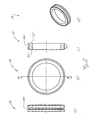
- Fig. 1 shows an inventive upper blade 7 in different views, which is designed to be placed on a harmonic 5 a cutting device 1 (see Fig. 4 ).
- the upper blade 7 differs from the known in the prior art upper blades by a circumferential groove 7 N, which serves as a driving engagement for a driver 130 (see Fig. 4 ) as described below.
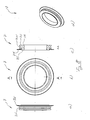
- Fig. 2 shows various views of a lower blade 11 according to the invention, which is designed to be arranged on a lower shaft 9 of the cutting device 1 (see Fig. 4 ).
- the lower blade 11 differs from the known in the art lower blades by a circumferential groove 11 N, which serves as a driving engagement for a driver 13U (see Fig. 4 ) as described below.
- Fig. 3 shows a disc knife pair 3, consisting of an upper blade 7 and a lower blade 11, in different views, the upper blade 7 and the lower blade 11 are in a cutting engagement, as it is made for example in the cutting device 1, when the outer blade 7 on the upper shaft 5 and the lower blade 11 is located on the lower shaft 9 in order to cut a passing through the cutting device 1 web material in strips.
- Fig. 4 shows the arranged on the upper shaft 5 upper blade 7 in cutting engagement with the arranged on the lower shaft 9 lower blade 11.
- the shafts 5, 9 is associated with a respective linear stage 250, 25U, which runs parallel to the associated shaft 5, 9.
- a driver 130, 13U On each linear stage 250, 25U, a driver 130, 13U is arranged so as to be longitudinally displaceable, wherein the positioning of the drivers 130, 13U takes place along the respective linear stage 250, 25U by means of a control (not shown).
- Fig. 5 shows the linear stage 25U with the driver 13U arranged thereon in a perspective view, but the linear table 250 and the driver 130 are each identical in construction.
- the cam 13U has a cam plate 13M which forms, along a peripheral portion, an engaging lip 13E which is substantially semicircular.
- the driver plate 13 M is by means of two Linerhubzylinder 27 in the vertical direction (in Fig. 5 from top to bottom) to raise and lower the engagement lip 13E relative to the stage 25U.
- the Linearhubzylinder 27 of the driver 13U are preferably each a pneumatic cylinder, and the activation of the Linearhubzylinder 27 is set by the controller, not shown.
- the lower blade 11 can be appropriately positioned along the lower shaft 9 by engaging the engaging lip 13E of the driver 13U with the groove 11N in the lower blade 11 by appropriately sliding the driver 13U along the linear table 25U and lifting it and lowering the engaging lip 13E by means of the Linearhubzylinder 27th
- Fig. 4 shows a storage area 17 of the cutting device 1, in which on the shafts 5, 9 arranged and not required for a current cutting operation knives 7, 11 may be arranged.
- the knives 7, 11 are arranged side by side in the storage area 17 so that they rest against each other and a knife pushed first into the storage area 17 bears against a stop 15 of the shafts 5, 9.
- the controller moves the dogs 130, 13U to an end of the shafts 5, 9 opposite the storage area 17 and activates the linear lifting cylinders 27 so that the engaging lip 13E is moved closer to the associated shaft 5, 9 than for engagement with a groove 7N, 11N is necessary.
- the control activates the linear stages 250, 25U in such a way that the drivers 130, 13U are displaced in the direction of the storage area 17.
- each driver plate 13M eventually strikes a side surface 7S of the upper blade 7 or a side surface 11S of the lower blade 11, and with a further displacement of the drivers 130, 13U in the direction of the storage region 17, all the knives 7, 11 become in the storage area 17 postponed.
- the marker 19 may be a bar mark on the shaft 5, 9 (perpendicular to the longitudinal axis) or may be formed by a laser pointer directed to the center of the shaft 5, 9 to align the groove 7N, 11N at a laser spot.
- a shifting force increases, which must apply the linear stage 250, 25U to move the knives 7, 11 in the storage area 17, as more and more knives 7, 11 through the Driver 130, 13U are moved while they move in the direction of the storage area 17.
- a pressure sensor 21 is arranged, which is in connection with the displacement control to determine the displacement force of the driver 130, 13U, while the drivers 130, 13U are moved in the direction of the storage area 17.
- a servo drive is used, which is to operate switchable between a speed control and a torque control.
- a further displacement finally proposes a rear side in the direction of displacement 7S, 11S of the first deferred knife 7, 11 to the stop 15 of the respective shaft 5, 9, whereby the measured by the pressure sensor 21 displacement force steadily increases, although the drivers 130, 13U do not move further in the direction of the storage area 17.
- the controller detects this situation (or exceeding a predetermined pressure force threshold) and stops moving the drivers 130, 13U.
- the drive current is monitored for the exceeding of a maximum value or determined at a torque control of the standstill by monitoring the position reporting signals.
- the knives 7, 11 are now arranged next to each other and abut each other, wherein a side surface of a first pushed on the shafts 5, 9 knife rests against the respective stop 15 of the shafts 5, 9. This standstill position is detected and stored by the control device.
- the controller calculates a total knife width MGL of the knives 7, 11 lined up, that is, the controller determines a distance between the drivers 130, 13U to the respective stop 15 of the associated shaft, 5, 9.
- the controller Since the controller knows the width of the knives 7, 11, the controller can calculate the number of knives 7, 11 on the associated shaft 5, 9 based on the total width of the knife MGL.
- the controller can also calculate the position of the grooves 7N, 11N of the knives 7, 11 on the shaft 5, 9.
- the controller then reverses the direction of displacement of the driver 13U, and six lower blades 11 are ejected from the storage area 17.
- the lower blade 11 engaged with the engaging lip 13E of the driver 13U is displaced along the lower shaft 9 until it has reached the desired position on the lower shaft 9.
- the knives 7, 11 are pushed individually out of the storage area 17 and suitably positioned.
- the cutting device 1 has only one linear stage with a driver which is movable between the upper shaft 5 and the lower shaft 9 in order to position the knives 7, 11.
- a linear table can, for example, be movable along a U-shaped path, wherein a shaft 5, 9 is arranged on each of the free legs of the U-shape.
- At least one radial lifting cylinder is advantageously arranged at the ends of at least one shaft 5, 9 in order to increase a mutual spacing of the shafts 5, 9, whereby the shafts 5, 9 are arranged relative to one another in a cutting position in which the upper knives 7 are in cutting engagement with the lower knives 11, and the shafts 5, 9 can be arranged on the other hand in a displacement position in which the upper knives 7 are not in cutting engagement with the lower knives 11 and independently along the respective shaft 5, 9 can be moved by the driver 130, 13U.
- the Radialhubzylinder the at least one shaft 5, 9 solve the knives 7, 11 thus before positioning them from their cutting engagement by moving the shafts 5, 9 in the traversing position for positioning the knives. After the positioning of the knives, the radial lifting cylinders move the shafts 5, 9 back into the cutting position, so that the upper knives 7 are in cutting engagement with the lower knife 11 in order to cut web material into strips.
- the Radialhubzylindern is preferably assigned in each case a Axialhubzylinder to adjust before performing the radial offset an axial displacement of the shafts 5, 9 in the longitudinal direction of the shafts 5, 9.
- a radial offset of the shafts is first set by means of Axialhubzylinder to move the shafts 5, 9 from the cutting position to the displacement position.
- the control moves the drivers 130, 13U against the respective stop 15 and reverses the direction of displacement of the respective driver 130, 13U, so that all the knives 7, 11 contact the End of the shaft 5, 9 are pushed, which is opposite to the storage area 17. Since the control of the number of knives 7, 11 on the respective shaft 5, 9 known, the displacement of the driver 130, 13U is stopped in time, so that the last deferred knife 7, 11 in a defined small distance from the free end the respective shaft 5, 9, which is opposite to the storage area 17.
- the knives 7, 11 are to be arranged differently at the end of a cutting process for a subsequent cutting operation, that is to say the number and / or the position of the knives 7, 11 are changed, the above-described steps for positioning the knives 7, 11 are repeated, that is, the sliding of all knives 7, 11 in the storage area 17 and the subsequent repositioning of the required knives 7, 11.
- the knives 7, 11 are fixed in a known manner on the respective shaft 5, 9, for example by a positive connection or a frictional connection.
- a positive connection can be achieved, for example, in that a wedge running along the longitudinal axis of the shaft 5, 9 in a groove is pressed by means of compressed air into a notch formed in the knives 7, 11. If no corresponding indentation is formed in the knives 7, 11, then there is a frictional connection between the wedge and the knives 7, 11.
- a plurality of longitudinally extending wedges may be provided, which preferably have a uniform angular offset with each other, in order to achieve the best possible adhesion between the shafts 5, 9 and the knives 7, 11.
- the shafts 5, 9 can rotate during the positioning of the knives 7, 11.
- the shafts 5, 9 are therefore advantageously associated with a cleaning device for the knives 7, 11 in order to free the side surfaces 7S, 11S from dust and the like.
- the cleaning means may be constituted, for example, by compressed air nozzles arranged at regular intervals along the longitudinal direction of the shafts 5, 9 to blow dust and the like from the side surfaces 7S, 11S of the knives 7, 11, preferably before performing the radial displacement of the shafts 5, 9.
- the cleaning device may alternatively or additionally be associated with the drivers 130 and 13U, which have, for example, compressed-air nozzles for cleaning the blades 7, 11 along the engagement lip 13E.
- the knives 7, 11 can be cleaned by moving the dogs 130, 13U along the entire length of the shafts 5, 9 to clean the knives 7, 11.
- the cleaning device can also be formed in the form of brushes or a rubber lip on the drivers 130, 13U, which mechanically clean the side surfaces 7S, 11S of the knives 7, 11 when the drivers 130, 13U come into engagement with the respective knives 7, 11 ,
- the knives 7, 11 may each have a spacer 7A, 11A in order to set a mutual distance between the knives 7, 11.
- Fig. 7 shows in different views an upper blade 7, the upper blade of the Fig. 1 to the fact that this additionally has a spacer 7A in the form of a circumferential spacer ring.
- Cutting dust accumulating during cutting of the continuous web material is deposited on the spacer 7A and can not protrude axially beyond the spacer 7A since otherwise it would fall off the upper blade 7. In this way it is ensured that the mutual distance between upper blades 7 is predetermined solely by the spacer 7A.
- Fig. 8 shows a variant of the upper blade 7 of Fig. 7 in which the spacer 7A is disposed on an opposite side surface 7S.
- the spacer 7A and a cutting blade 7K of the upper blade 7 are thus arranged on opposite side surfaces 7S of the upper blade 7.
- Fig. 9 shows various views of a lower blade 11, the lower blade of the Fig. 2 to the extent that it has a spacer 11A.
- the spacer 11A is in turn formed as a circumferential spacer ring.
- the spacers 7 A, 11 A of Fig. 7 to 9 are each shown as a circumferential spacer ring.
- the spacers 7A, 11A may each be formed by offset-spaced spacers, for example by four spacer tabs, which are arranged at an angular offset of 90 ° to each other on a side surface 7S, 11S.
- spacers 7A are used in the upper knives, spacers 11A need not necessarily be used on the lower knives, and vice versa.
- the described knives 7, 11 can first be pushed onto a shaft 5, 9 both with the one side surface 7S, 11S and also with the opposite side surface 7S, 11S, that is to say they can be used on both sides.
- the control since the grooves 7N, 11N of the knives 7, 11 are arranged asymmetrically, the control must be entered before positioning the knives 7, 11 of the control device in which orientation they have been slid to match the position of the grooves 7N, 11N calculated.
Abstract
Description
Die Erfindung betrifft ein Verfahren zum Positionieren von Messern einer Schneidvorrichtung, die horizontal gerichtet durchlaufendes Bahnmaterial in Streifen mittels mindestens eines Tellermesserpaares schneidet, das auf einer Oberwelle ein tellerförmiges Obermesser und auf einer Unterwelle ein zugeordnetes das Obermesser schneidend berührendes Untermesser aufweist.The invention relates to a method for positioning knives of a cutting device which cuts horizontally oriented web material into strips by means of at least one pair of divider blades having a plate-shaped upper blade on a harmonic and an associated lower blade contacting the upper blade on a lower shaft.
Die Erfindung betrifft ferner eine Schneidvorrichtung zur Durchführung des Verfahrens und zum Schneiden von horizontal gerichtet durchlaufendem Bahnmaterial in Streifen mittels mindestens eines Tellermesserpaares, das auf einer Oberwelle ein tellerförmiges Obermesser und auf einer Unterwelle ein zugeordnetes, das Obermesser schneidend berührendes Untermesser aufweist.The invention further relates to a cutting device for carrying out the method and for cutting horizontally directed passing web material in strips by means of at least one pair of divider blades having on a harmonic a plate-shaped upper blade and on a lower shaft an associated, the upper blade cuttingly touching lower blade.
Aus der
Ein Nachteil des bekannten Verfahren ist, daß die Messer auf der Welle von Hand vorpositioniert werden, wodurch eine erhebliche Verletzungsgefahr gegeben ist.A disadvantage of the known method is that the knives are pre-positioned on the shaft by hand, whereby a considerable risk of injury is given.
Ein Nachteil der Verschiebeeinrichtung der Schneidvorrichtung ist, daß die Finger der Verschiebeeinrichtung für eine Anlage sowohl an einer in Verschieberichtung vorderen wie auch hinteren Seitenfläche eines Messers ausgelegt sind, wodurch sich eine relativ aufwendige Steuerung der Verschiebeeinrichtung ergibt, die die jeweilige Art des Eingriffs berücksichtigen muss.A disadvantage of the displacement device of the cutting device is that the fingers of the displacement device for a system are designed both on a front and rear side surface of a knife in the displacement direction, resulting in a relatively complex control of the displacement device, which must take into account the respective type of engagement.
Aufgabe der vorliegenden Erfindung ist es daher, ein Verfahren zum Positionieren von Messern einer Schneidvorrichtung und eine zugehörige Schneidvorrichtung anzugeben, durch die bei verkürzter Rüstzeit die Einstellgenauigkeit und die Arbeitssicherheit erhöht ist, und eine Verschiebeeinrichtung anzugeben, die einen einfacheren Aufbau aufweist.The object of the present invention is therefore to provide a method for positioning knives of a cutting device and an associated cutting device, by the setting accuracy and safety is increased with a shorter set-up time, and to provide a displacement device having a simpler structure.
Diese Aufgabe wird erfindungsgemäß verfahrensseitig bei einem gattungsgemäßen Verfahren gelöst durch: a) Anordnen einer Anzahl von Messern auf einer Welle, b) Verschieben aller Messer mittels eines Mitnehmers gegen einen Anschlag, so daß diese in einem Vorratsbereich der Welle nebeneinander angeordnet sind und aneinander anliegen, c) Bestimmen einer Breite der aneinander anliegenden Messer in dem Vorratsbereich entlang der Welle (Messergesamtbreite), d) Berechnen der Anzahl der Messer in dem Vorratsbereich mittels der Messergesamtlänge sowie Berechnen der Lage von Mitnehmereingriffen jedes Messers, die zum Zusammenwirken mit dem Mitnehmen ausgelegt sind, um diese entlang der Welle geeignet zu positionieren, und e) Positionieren der Messer auf der Welle durch Verschieben derselben aus dem Vorratsbereich entlang der Welle in eine gewünschte Position mittels des Mitnehmers.This object is achieved on the method side in a generic method by: a) arranging a number of knives on a shaft, b) moving all the knives by means of a driver against a stop, so that they are arranged side by side in a storage area of the shaft and abut each other, c) determining a width of the adjacent knives in the storage area along the shaft (total knife width), d) calculating the number of knives in the storage area by means of the total knife length and calculating the location of entrainment operations of each knife designed to co-operate with the takeaway; to properly position them along the shaft; and e) positioning the knives on the shaft by sliding them out of the storage area along the shaft to a desired position by means of the follower.
Vorteilhaft werden die Messer im Schritt a) von Hand auf die Welle geschoben.Advantageously, the knives are pushed onto the shaft by hand in step a).
Bevorzugt wird ein als letztes auf die Welle geschobenes Messer an einer Markierung ausgerichtet, so daß sich der Mitnehmereingriff dieses Messers an einer definierten Position auf der Welle zum Eingriff mit dem Mitnehmer befindet.Preferably, a last pushed onto the shaft knife is aligned with a mark, so that the driving engagement of this knife is located at a defined position on the shaft for engagement with the driver.
Bevorzugt wird ein Antrieb mit einer jeweils einzuschaltenden Momentenbegrenzung eingesetzt und im Schritt b) ein merklicher Stillstand und/oder eine Verschiebekraft von einem Drucksensor gemessen und an eine Steuerung für den Mitnehmer übermittelt, wobei der Verschiebeantrieb im Schritt b) von der Steuerung beendet wird, wenn der Stillstand länger als eine vorgegebene Maximalzeit oder der Wert der gemessenen Kraft einen vorbestimmten Kraftschwellwert überschreitet. Die jeweilige Mitnehmerposition wird von der Steuervorrichtung erfasst und gespeichert. Ein Stillstand lässt sich anhand einer Konstanz der Positionsmeldung oder am Ausbleiben von Schrittmeldesignalen oder an einer Überschreitung eines Servostrommesswertes ermitteln.Preferably, a drive is used with a torque limit to be turned on and in step b) a noticeable standstill and / or a displacement force measured by a pressure sensor and transmitted to a controller for the driver, wherein the displacement drive in step b) is terminated by the controller, if the standstill exceeds a predetermined maximum time or the value of the measured force exceeds a predetermined force threshold. The respective driving position is detected and stored by the control device. A standstill can be determined on the basis of a constancy of the position signal or the absence of step signal signals or an overrun of a servo output measured value.
Vorteilhaft wird im Schritt e) der Mitnehmer mit einem Mitnehmereingriff des Messers in Eingriff gebracht und der Mitnehmer durch die Steuerung positionsgesteuert entlang der Welle verfahren, wodurch die Messer positioniert werden.Advantageously, in step e), the driver is brought into engagement with a driver engagement of the knife and the driver is moved position-controlled by the controller along the shaft, whereby the knives are positioned.
In einer ersten Variante werden die Messer im Schritt e) von dem Mitnehmer nacheinander aus dem Vorratsbereich geschoben und positioniert.In a first variant, the knives are successively pushed out of the storage area and positioned by the driver in step e).
In einer zweiten Variante wird im Schritt e) der Mitnehmer in Eingriff gebracht mit einem Mitnehmereingriff eines geeigneten Messers, um dann eine benötigte Anzahl von Messern aus dem Vorratsbereich auszuschieben, wobei dieses Messer derart entlang der Welle verschoben wird, bis es an einer gewünschten Stelle angeordnet ist, und folgend wird der Mitnehmer gelöst und in Eingriff gebracht mit einem in Verschieberichtung benachbarten Messer, das dann wiederum wie gewünscht positioniert wird, und diese Schritte werden wiederholt, bis die benötigte Anzahl von Messern wie gewünscht positioniert ist.In a second variant, in step e), the driver is engaged with a driving engagement of a suitable knife to then eject a required number of knives from the storage area, said knife being displaced along the shaft until it is located at a desired location and subsequently, the follower is released and engaged with a knife adjacent in the direction of displacement, which in turn is then positioned as desired, and these steps are repeated until the required number of knives are positioned as desired.
Bevorzugt greift der Mitnehmer im Schritt b) an einer in Verschieberichtung vorderen Seitenfläche des letzten aufgeschobenen Messers an, um die Messer zu verschieben.Preferably, the driver engages in step b) on a front side in the direction of displacement side of the last deferred knife to move the knife.
Die Obermesser und die Untermesser können von demselben Mitnehmer oder jeweils von einem eigenen zugehörigen Mitnehmer verschoben werden.The upper knife and the lower knife can be moved by the same driver or in each case by its own associated driver.
Bevorzugt werden die Wellen vor dem Schritt a) zunächst relativ zueinander axial versetzt (Axialversatz) und folgend senkrecht dazu relativ zueinander versetzt (Radialversatz), um die Messer aus ihrem schneidenden Eingriff zu lösen, und nach dem Schritt e) wird zunächst der Radialversatz und folgend der Axialversatz durch entsprechend entgegengesetzte Bewegungssteuerungen kompensiert, um die Messer im schneidenden Eingriff zu positionieren.Preferably, before the step a), the shafts are initially offset axially relative to one another (axial offset) and subsequently perpendicular thereto (radial offset) to disengage the blades from their cutting engagement, and after step e) the radial offset and following are first the axial offset compensated by correspondingly opposite motion controls to position the blades in the cutting engagement.
Die Aufgabe wird vorrichtungsseitig bei einer gattungsgemäßen Schneidvorrichtung dadurch gelöst, daß das mindestens eine Ober- und Untermesser jeweils eine umlaufende Nut aufweisen, und daß der bzw. die beiden Mitnehmer jeweils eine dazu passende Eingriffslippe zur Kopplung mit dem mindestens einem Ober- bzw. einen Untermesser aufweisen.The object is achieved on the device side in a generic cutting device in that the at least one upper and lower blade each have a circumferential groove, and that the or the two drivers each have a mating engagement lip for coupling with the at least one upper or a lower blade exhibit.
Bevorzugt ist die Eingriffslippe ein Umfangsabschnitt einer im wesentlichen rechteckigen Mitnehmerplatte.Preferably, the engagement lip is a peripheral portion of a substantially rectangular cam plate.
Vorteilhaft ist bzw. sind der bzw. die Mitnehmer jeweils auf einem Lineartisch angeordnet, der parallel zu der Oberwelle und der Unterwelle verläuft.Advantageously, the driver or carriers are respectively arranged on a linear stage which runs parallel to the harmonic and the lower shaft.
Vorteilhaft ist die Eingriffslippe im wesentlichen halbkreisförmig.Advantageously, the engagement lip is substantially semicircular.
Bevorzugt ist jedem Lineartisch mindestens ein Linearhubzylinder zum Anheben und Absenken der Eingriffslippe relativ zu dem Lineartisch zugeordnet, um die Eingriffslippe des Mitnehmers in Eingriff mit einer Nut eines Messers zu bringen.Preferably, each linear stage is associated with at least one linear lift cylinder for raising and lowering the engagement lip relative to the linear stage to engage the engagement lip of the follower with a groove of a knife.
Bevorzugt ist an gegenüberliegenden Enden der Oberwelle und/oder der Unterwelle jeweils ein Radialhubzylinder angeordnet, der den Radialversatz erzeugt.Preferably, a radial stroke cylinder is arranged at opposite ends of the upper shaft and / or the lower shaft, which generates the radial offset.
Bevorzugt ist an den gegenüberliegenden Enden der Oberwelle und/oder der Unterwelle jeweils ein Axialhubzylinder angeordnet, der den Axialversatz erzeugt.Preferably, in each case an axial stroke cylinder is arranged at the opposite ends of the upper shaft and / or the lower shaft, which generates the axial displacement.
Vorteilhaft weist das mindestens eine Obermesser und/oder das mindestens eine Untermesser jeweils einen Abstandhalter auf, um einen geeigneten gegenseitigen axialen Abstand der Messer einzustellen.Advantageously, the at least one upper blade and / or the at least one lower blade each have a spacer in order to set a suitable mutual axial distance of the blades.
Bevorzugt ist der Abstandshalter ein umlaufender Abstandsring.Preferably, the spacer is a circumferential spacer ring.
Die Schneidvorrichtung weist vorteilhaft 10, 15, 20, 25 oder 30 Tellermesserpaare auf.The cutting device advantageously has 10, 15, 20, 25 or 30 disc knife pairs.
Vorteilhaft ist das Bahnmaterial eine Papierbahn oder eine Folienbahn, beispielsweise aus PVC, PP, PE oder PU, eine Sandwichfolienbahn, eine Laminatbahn, eine Textilbahn, eine Metallblechbahn oder eine Kantenmaterialbahn, beispielsweise aus Furnier, ABS oder Melaminharz.The web material is advantageously a paper web or a film web, for example made of PVC, PP, PE or PU, a sandwich film web, a laminate web, a textile web, a metal sheet web or an edge material web, for example of veneer, ABS or melamine resin.
Die Erfindung wird nachfolgend anhand eines Ausführungsbeispiels unter Bezug auf eine Zeichnung erläutert. Es zeigen:
-
Fig. 1a, b, c und d eine Seiten-, Front-, Querschnitts- und perspektivische Ansicht eines erfindungsgemäßen Obermessers einer Schneidvorrichtung; -
Fig. 2a, b, c und d eine Seiten, Front-, Querschnitts- und perspektivische Ansicht eines erfindungsgemäßen Untermessers einer Schneidvorrichtung; -
Fig. 3a, b und c eine Front-, Querschnitts- und perspektivische Ansicht des Obermessers derFig. 1 , das im schneidenden Eingriff mit dem Untermesser derFig. 2 steht; -
Fig. 4 eine schematische Darstellung eines Ausschnitts einer erfindungsgemäßen Schneidvorrichtung, die auf einer Oberwelle das erfindungsgemäße Obermesser derFig. 1 und auf einer Unterwelle das erfindungsgemäße Untermesser derFig. 2 trägt, wobei den Messern jeweils ein Mitnehmer auf einem Lineartisch zugeordnet ist, womit die Messer zu verschieben sind; -
Fig. 5 eine perspektivische Ansicht eines Mitnehmers derFig.4 ; -
Fig. 6 eine schematische Darstellung vom mehreren erfindungsgemäßen Untermessern auf einer Unterwelle, wobei eine Teil der Untermesser durch die Verschiebeeinrichtung auf der Unterwelle positioniert wird; -
Fig. 7a, b, c und d eine Seiten-, Front-, Querschnitts- und perspektivische Ansicht einer ersten Variante des erfindungsgemäßen Obermessers; -
Fig. 8a, b, c und d eine Seiten-, Front-, Querschnitts- und perspektivische Ansicht einer zweiten Variante des erfindungsgemäßen Obermessers; und -
Fig. 9a, b, c und d eine Seiten-, Front-, Querschnitts- und perspektivische Ansicht einer Variante des erfindungsgemäßen Untermessers.
-
Fig. 1a, b, c and d a side, front, cross-sectional and perspective view of a top blade according to the invention a cutting device; -
Fig. 2a, b, c and d a side, front, cross-sectional and perspective view of a lower blade according to the invention a cutting device; -
Fig. 3a, b and c a front, cross-sectional and perspective view of the upper blade ofFig. 1 , which in cutting engagement with the lower blade of theFig. 2 stands; -
Fig. 4 a schematic representation of a section of a cutting device according to the invention, the inventive upper blade on a harmonicFig. 1 and on a lower shaft, the lower blade of the inventionFig. 2 carries, wherein the knives each a driver is assigned to a linear table, which are the blades to move; -
Fig. 5 a perspective view of a driver ofFigure 4 ; -
Fig. 6 a schematic representation of several lower blades according to the invention on a lower shaft, wherein a part of the lower blade is positioned by the displacement device on the lower shaft; -
Fig. 7a, b, c and d a side, front, cross-sectional and perspective view of a first variant of the upper blade according to the invention; -
Fig. 8a, b, c and d a side, front, cross-sectional and perspective view of a second variant of the upper blade according to the invention; and -
Fig. 9a, b, c and d a side, front, cross-sectional and perspective view of a variant of the lower blade according to the invention.
Das Obermesser 7 unterscheidet sich von den im Stand der Technik bekannten Obermessern durch eine umlaufende Nut 7N, die als Mitnehmereingriff für einen Mitnehmer 130 dient (siehe
Das Untermesser 11 unterscheidet sich von den im Stand der Technik bekannten Untermessern durch eine umlaufende Nut 11N, die als Mitnehmereingriff für einen Mitnehmer 13U dient (siehe
Auf jedem Lineartisch 250, 25U ist jeweils ein Mitnehmer 130, 13U längsverschieblich angeordnet, wobei die Positionierung der Mitnehmer 130, 13U entlang des jeweiligen Lineartisches 250, 25U mittels einer nicht dargestellten Steuerung erfolgt.On each
Der Mitnehmer 13U weist eine Mitnehmerplatte 13M auf, die entlang eines Umfangsabschnitts eine Eingriffslippe 13E bildet, die im wesentlichen halbkreisförmig ist.The
Die Mitnehmerplatte 13M ist mittels zweier Linerhubzylinder 27 in vertikaler Richtung (in
Die Linearhubzylinder 27 des Mitnehmers 13U sind bevorzugt jeweils ein Pneumatikzylinder, und die Aktivierung der Linearhubzylinder 27 wird von der nicht dargestellten Steuerung vorgegeben.The
Wie weiter unten beschrieben, kann das Untermesser 11 entlang der Unterwelle 9 geeignet positioniert zu werden, indem die Eingriffslippe 13E des Mitnehmers 13U in Eingriff gebracht wird mit der Nut 11N in dem Untermesser 11, durch geeignetes Verschieben des Mitnehmers 13U entlang des Lineartisches 25U und Anheben und Absenken der Eingriffslippe 13E mittels der Linearhubzylinder 27.As described below, the
Unter Bezug auf
Zunächst wird eine vorgegebene Anzahl von Messern 7, 11 von Hand beliebig auf der zugehörigen Welle 5, 9 angeordnet, vorzugsweise nur ein kurzes Stück auf die Wellen 5, 9 geschoben.First, a predetermined number of
Folgend verfährt die Steuerung die Mitnehmer 130, 13U an ein dem Vorratsbereich 17 gegenüberliegendes Ende der Wellen 5, 9 und aktiviert die Linearhubzylinder 27 derart, daß die Eingriffslippe 13E näher an die zugehörige Welle 5, 9 gefahren wird, als für einen Eingriff mit einer Nut 7N, 11N notwendig ist.Subsequently, the controller moves the
Die Steuerung aktiviert die Lineartische 250, 25U folgend derart, daß die Mitnehmer 130, 13U in Richtung auf den Vorratsbereich 17 verschoben werden.The control activates the
Während dieses Verschiebevorgangs schlägt jede Mitnehmerplatte 13M irgendwann an eine Seitenfläche 7S des Obermessers 7 bzw. eine Seitenfläche 11S des Untermessers 11 an, und bei einer weiteren Verschiebung der Mitnehmer 130, 13U in Richtung auf den Vorratsbereich 17 werden alle Messer 7, 11 in den Vorratsbereich 17 verschoben.During this shifting operation, each
In einer alternativen Ausführungsform wird das zuletzt auf die Welle 5, 9 geschobene Messer 7, 11 an einer Markierung 19 ausgerichtet, so daß der Steuerung die Lage der Nut 7N bzw. 11N bekannt ist, wodurch die Eingriffslippe 13E eines jeden Mitnehmers 130, 13U durch die Steuerung derart bewegt werden kann, daß sie in Eingriff kommt mit der jeweiligen Nut 7N, 11N, um durch den dann gebildeten Formfluss das zuletzt aufgeschobene Messer 7, 11 in Richtung des Vorratsbereichs 17 zu verschieben. Die Markierung 19 kann eine Strichmarkierung auf der Welle 5, 9 sein (senkrecht zur Längsachse) oder kann durch einen Laserpointer gebildet sein, der auf den Mittelpunkt der Welle 5, 9 gerichtet ist, um die Nut 7N, 11N an einem Laserpunkt auszurichten.In an alternative embodiment, the last pushed onto the
Während des Verschiebens der Messer 7, 11 in Richtung auf den Vorratsbereicht 17 steigt eine Verschiebekraft an, die der Lineartisch 250, 25U aufbringen muss, um die Messer 7, 11 in den Vorratsbereich 17 zu verschieben, da immer mehr Messer 7, 11 durch die Mitnehmer 130, 13U verschoben werden, während sich diese in Richtung auf den Vorratsbereich 17 bewegen. An den Mitnehmer 130, 13U ist beispielsweise ein Drucksensor 21 angeordnet, der in Verbindung mit der Verschiebesteuerung steht, um die Verschiebekraft der Mitnehmer 130, 13U zu bestimmen, während die Mitnehmer 130, 13U in Richtung auf den Vorratsbereich 17 bewegt werden. Vorzugsweise kommt ein Servoantrieb zum Einsatz, der zwischen einer Drehzahlregelung und einer Momentenregelung umschaltbar zu betreiben ist.During the displacement of the
Werden die Mitnehmer 130, 13U weiter in Richtung auf den Vorratsbereich 17 verschoben, so liegen schließlich alle Messer 7, 11 aneinander an, wobei das zuletzt aufgeschobene Messer an dem Mitnehmer 130, 13U anliegt.If the
Bei einem weiteren Verschieben schlägt schließlich eine in Verschieberichtung hintere Seitenfläche 7S, 11S des zuerst aufgeschobenen Messers 7, 11 an dem Anschlag 15 der jeweiligen Welle 5, 9 an, wodurch die mittels des Drucksensors 21 gemessene Verschiebekraft stetig ansteigt, obwohl die Mitnehmer 130, 13U sich nicht weiter in Richtung des Vorratsbereichs 17 bewegen. Die Steuerung erfasst diese Situation (oder das Überschreiten eines vorgegebenen Druckkraftschwellwerts) und stoppt das Verschieben der Mitnehmer 130, 13U. Alternativ wird bei einem drehzahlgeregeltem Servoantrieb der Antriebsstrom auf das Überschreiten eines Maximalwertes überwacht oder bei einer Momentenregelung der Stillstand durch eine Überwachung der Positionsmeldesignale ermittelt.In a further displacement finally proposes a rear side in the direction of displacement 7S, 11S of the first
Die Messer 7, 11 sind nun nebeneinander angeordnet und liegen aneinander an, wobei eine Seitenfläche eines zuerst auf die Wellen 5, 9 geschobenen Messers an dem jeweiligen Anschlag 15 der Wellen 5, 9 anliegt. Diese Stillstandposition wird erfasst und von der Steuervorrichtung gespeichert.The
Die Steuerung berechnet anhand der nun erreichten Position der Mitnehmer 130, 13U eine Messergesamtbreite MGL der aneinander gereihten Messer 7, 11, das heißt die Steuerung bestimmt einen Abstand der Mitnehmer 130, 13U zu dem jeweiligen Anschlag 15 der zugehörigen Welle, 5, 9.Based on the position of the
Da der Steuerung die Breite der Messer 7, 11 bekannt ist, kann die Steuerung anhand der Messergesamtbreite MGL die Anzahl der Messer 7, 11 auf der zugehörigen Welle 5, 9 berechnen.Since the controller knows the width of the
Mit Hilfe der Messergesamtbreite MGL und der Anzahl der Messer kann die Steuerung ferner die Lage der Nuten 7N, 11N der Messer 7, 11 auf der Welle 5, 9 berechnen.With the aid of the total knife width MGL and the number of knives, the controller can also calculate the position of the
Um nun eine für einen Schneidvorgang benötigte Anzahl von Messern 7, 11 auf der zugehörigen Welle 5, 9 anzuordnen, beispielsweise sechs Untermesser 11, wird die Eingriffslippe 13E des Mitnehmers 13U derart in den Vorratsbereich 17 verfahren, daß sie mit der Nut 11N des sechsten Untermessers 11 in Eingriff kommt.In order now to arrange a number of
Die Steuerung kehrt dann die Verschieberichtung des Mitnehmers 13U um, und es werden sechs Untermesser 11 aus dem Vorratsbereich 17 ausgeschoben.The controller then reverses the direction of displacement of the
Das mit der Eingriffslippe 13E des Mitnehmers 13U in Eingriff stehende Untermesser 11 wird solange entlang der Unterwelle 9 verschoben, bis es die gewünschte Position auf der Unterwelle 9 eingenommen hat.The
Dann wird die Eingriffslippe 13E von dem sechsten Untermesser 11 gelöst, in Verschieberichtung verfahren und in Eingriff gebracht mit dem fünften Untermesser 11.Then, the
Nun werden fünf Untermesser durch den Lineartisch 25U weiter verschoben, bis das fünfte Untermesser 11 an der gewünschten Position angeordnet ist.Now, five lower blades are further shifted by the
Wiederum wird der Eingriff zwischen der Eingriffslippe 13E und der Nut 11N des fünften Untermessers 11 gelöst, wenn das fünfte Untermesser 11 geeignet positioniert ist, und die Eingriffslippe 13E wird in Eingriff gebracht mit der Nut 11N des vierten Untermessers 11, wie in
Dieser Vorgang wiederholt sich, bis sämtliche Untermesser 11 positioniert sind. Die Obermesser 7 werden auf die gleiche Weise positioniert.This process is repeated until all
Alternativ werden die Messer 7, 11 einzeln aus dem Vorratsbereich 17 geschoben und geeignet positioniert.Alternatively, the
In dem vorliegenden Ausführungsbeispiel ist jeder Welle 5, 9 ein Lineartisch 250, 25U mit einem Mitnehmer 130, 13U zugeordnet. Alternativ weist die Schneidvorrichtung 1 nur einen Lineartisch mit einem Mitnehmer auf, der zwischen der Oberwelle 5 und der Unterwelle 9 verfahrbar ist, um die Messer 7, 11 zu positionieren. Ein derartiger Lineartisch kann beispielsweise entlang einer U-förmigen Bahn verfahrbar sein, wobei an den freien Schenkeln der U-Form jeweils eine Welle 5, 9 angeordnet ist.In the present embodiment, each
An den Enden mindestens einer Welle 5,9 ist vorteilhaft jeweils mindestens ein Radialhubzylinder angeordnet, um einen gegenseitigen Abstand der Wellen 5, 9 zu vergrößern, wodurch die Wellen 5, 9 zum einen in einer Schneidstellung relativ zueinander angeordnet werden können, in der die Obermesser 7 in schneidendem Eingriff mit den Untermessern 11 stehen, und die Wellen 5, 9 zum anderen in einer Verfahrstellung angeordnet werden können, in der die Obermesser 7 nicht in schneidendem Eingriff mit den Untermessern 11 stehen und unabhängig voneinander entlang der jeweiligen Welle 5, 9 durch die Mitnehmer 130, 13U verschoben werden können. Die Radialhubzylinder der mindestens einen Welle 5, 9 lösen die Messer 7, 11 somit vor dem Positionieren derselben aus ihrem schneidenden Eingriff, indem sie die Wellen 5, 9 in die Verfahrposition zur Positionierung der Messer verfahren. Nach der Positionierung der Messer verfahren die Radialhubzylinder die Wellen 5, 9 wieder in die Schneidstellung, so daß die Obermesser 7 in schneidendem Eingriff mit den Untermessers 11 stehen, um Bahnmaterial in Streifen zu schneiden.At least one radial lifting cylinder is advantageously arranged at the ends of at least one
Den Radialhubzylindern ist bevorzugt jeweils ein Axialhubzylinder zugeordnet, um vor dem Ausführen des Radialversatzes ein Axialversatz der Wellen 5, 9 in Längsrichtung der Wellen 5, 9 einzustellen. In diesem Fall wird zuerst mit Hilfe der Axialhubzylinder ein Axialversatz und folgend mit Hilfe der Radialhubzylinder ein Radialversatz der Wellen eingestellt, um die Wellen 5, 9 aus der Schneidstellung in die Verfahrstellung zu bewegen.The Radialhubzylindern is preferably assigned in each case a Axialhubzylinder to adjust before performing the radial offset an axial displacement of the
Um die auf den Wellen 5, 9 angeordneten Messer 7, 11 vollständig auszutauschen, verfährt die Steuerung die Mitnehmer 130, 13U an den jeweiligen Anschlag 15 und kehrt die Verschieberichtung des jeweiligen Mitnehmers 130, 13U um, so daß alle Messer 7, 11 an das Ende der Welle 5, 9 geschoben werden, das dem Vorratsbereich 17 gegenüberliegt. Da der Steuerung die Anzahl der Messer 7, 11 auf der jeweiligen Welle 5, 9 bekannt ist, wird das Verschieben der Mitnehmer 130, 13U zeitig angehalten, so daß sich das zuletzt aufgeschobene Messer 7, 11 in einen definierten geringen Abstand von dem freien Ende der jeweiligen Welle 5, 9 befindet, das dem Vorratsbereich 17 gegenüberliegt.In order to completely exchange the
Sollen die Messer 7, 11 am Ende eines Schneidvorgangs für einen folgenden Schneidvorgang anders angeordnet werden, das heißt die Anzahl und/oder die Lage der Messer 7, 11 geändert werden, so werden die zuvor beschriebenen Schritte zur Positionierung der Messer 7, 11 wiederholt, das heißt das Schieben aller Messer 7, 11 in den Vorratsbereich 17 und das folgende Neupositionieren der benötigten Messer 7, 11.If the
Die Messer 7, 11 werden in bekannter Weise auf der jeweiligen Welle 5, 9 befestigt, beispielsweise durch einen Formschluss oder einen Kraftschluss. Ein Formschluss kann beispielsweise dadurch erreicht werden, daß ein entlang der Längsachse der Welle 5, 9 in einer Nut verlaufender Keil mittels Druckluft in eine Einkerbung gedrückt wird, die in den Messern 7, 11 gebildet ist. Ist in den Messern 7, 11 keine entsprechende Einkerbung gebildet, so kommt es zu einem Kraftschluss zwischen dem Keil und den Messern 7, 11. Insbesondere bei der letzteren Variante können mehrere in Längsrichtung verlaufende Keile vorgesehen sein, die untereinander bevorzugt einen gleichmäßigen Winkelversatz aufweisen, um einen möglichst guten Kraftschluss zwischen den Wellen 5, 9 und den Messern 7, 11 zu erzielen.The
Um das Verschieben der Messer 7, 11 auf den Wellen 5, 9 zu vereinfachen, können sich die Wellen 5, 9 während der Positionierung der Messer 7, 11 drehen.In order to simplify the displacement of the
Bei dieser Art der Positionierung der Messer 7, 11 ist entscheidend, daß diese in dem Vorratsbereich 17 direkt aneinander anliegen und nicht durch beispielsweise Hausstaub oder Schneidstaub voneinander getrennt sind, wodurch anderenfalls die Bestimmung der Messergesamtbreite MGL mit einem Fehler behaftet wäre und die Berechnung der Anzahl der Messer 7, 11 und insbesondere die Berechnung der Lage der Nuten 7N, 11N nicht mit der erforderlichen Genauigkeit durchgeführt werden könnte. Den Wellen 5, 9 ist daher vorteilhaft eine Reinigungseinrichtung für die Messer 7, 11 zugeordnet, um die Seitenflächen 7S, 11 S von Staub und dergleichen zu befreien. Die Reinigungseinrichtung kann beispielsweise durch Druckluftdüsen gebildet sein, die entlang der Längsrichtung der Wellen 5,9 in regelmäßigen Abständen angeordnet sind, um Staub und dergleichen von den Seitenflächen 7S, 11S der Messer 7, 11 zu blasen, vorzugsweise vor dem Ausführen des Radialversatzes der Wellen 5, 9. Die Reinigungseinrichtung kann alternativ oder zusätzlich den Mitnehmern 130 und 13U zugeordnet sein, die entlang der Eingriffslippe 13E beispielsweise Druckluftdüsen zum Reinigen der Messer 7, 11 aufweisen. In diesem Fall können die Messer 7, 11 dadurch gereinigt werden, daß die Mitnehmer 130, 13U entlang der gesamten Länge der Wellen 5, 9 verfahren, um die Messer 7, 11 zu reinigen. Die Reinigungseinrichtung kann ferner in Form von Bürsten oder einer Gummilippe auf den Mitnehmern 130, 13U gebildet sein, die die Seitenflächen 7S, 11S der Messer 7, 11 mechanisch reinigen, wenn die Mitnehmer 130, 13U in Eingriff mit den jeweiligen Messern 7, 11 kommen.In this type of positioning of the
Alternativ oder zusätzlich zu einer Reinigungseinrichtung können die Messer 7, 11 jeweils einen Abstandshalter 7A, 11A aufweisen, um einen gegenseitigen Abstand zwischen den Messern 7, 11 einzustellen.As an alternative or in addition to a cleaning device, the
Die Abstandhalter 7A, 11 A der
Werden beispielsweise Abstandshalter 7A bei den Obermessern verwendet, so müssen nicht zwangsläufig ebenso Abstandshalter 11A an den Untermessern verwendet werden und umgekehrt.For example, if spacers 7A are used in the upper knives, spacers 11A need not necessarily be used on the lower knives, and vice versa.
Die beschriebenen Messer 7, 11 können sowohl mit der einen Seitenfläche 7S, 11 S wie auch mit der gegenüberliegenden Seitenfläche 7S, 11S zuerst auf eine Welle 5, 9 geschoben werden, das heißt sie sind beidseitig verwendbar. Da die Nuten 7N, 11N der Messer 7, 11 jedoch asymmetrisch angeordnet sind, muss der Steuerung vor dem Positionieren der Messer 7, 11 der Steuervorrichtung eingegeben werden, in welcher Orientierung diese aufgeschoben worden sind, damit sie die Lage der Nuten 7N, 11N zutreffend berechnet.The described
- 11
- Schneidvorrichtungcutter
- 33
- TellermesserpaarMesser couple
- 55
- Oberwelleharmonic
- 77
- Obermesserupper blade
- 7A7A
- Abstandshalter des Obermessers (Abstandsring)Spacer of the upper knife (spacer ring)
- 7K7K
- Klinge des ObermessersBlade of the upper knife
- 7N7N
- Nut im ObermesserGroove in the upper knife
- 7S7S
- Seitenfläche des ObermessersSide surface of the upper knife
- 99
- Unterwellelower shaft
- 1111
- Untermesserlower blade
- 11A11A
- Abstandshalter des Untermessers (Abstandsring)Spacer of the lower blade (spacer ring)
- 11N11N
- Nut im UntermesserGroove in the lower blade
- 11 S11 p
- Seitenfläche des UntermessersSide surface of the lower blade
- 130130
- Mitnehmer für ObermesserDriver for upper knife
- 13U13U
- Mitnehmer für UntermesserDriver for lower knife
- 13E13E
-
Eingriffslippe der Mitnehmer 130, 13UEngaging lip of the
driver - 13M13M
-
Mitnehmerplatte der Mitnehmer 130, 13UCarrier plate of the
driver - 1515
- Anschlagattack
- 1717
- Vorratsbereichstorage area
- 1919
- Markierungmark
- 2121
- Drucksensorpressure sensor
- 250250
- Lineartisch für OberwelleLinear table for harmonic
- 25U25U
- Lineartisch für UnterwelleLinear table for lower shaft
- 2727
- LinearhubzylinderLinearhubzylinder
- MGLMGL
- MessergesamtbreiteKnife Overall Width
Claims (21)
dadurch gekennzeichnet, daß
das jeweils mindestens eines der zugeordneten Ober- und Untermesser (7, 11) jeweils eine umlaufende Nut (7N, 11N) aufweist/en, und daß der bzw. die beiden Mitnehmer (130, 13U) jeweils eine dazu passende Eingriffslippe (13E) zur Kopplung mit dem mindestens einen Ober- bzw. Untermesser (7, 11) aufweisen.Cutting device for carrying out the method according to one of the preceding claims and for cutting horizontally directed passing web material in strips by means of at least one pair of divider blades (3) on a harmonic (5) a plate-shaped upper blade (7) and on a lower shaft (9) an associated comprising upper blade (7) intersecting lower blade (11),
characterized in that
each of at least one of the associated upper and lower blades (7, 11) each have a circumferential groove (7N, 11N) / s, and that the or the two drivers (130, 13U) each have a mating engagement lip (13E) for Coupling with the at least one upper or lower blade (7, 11).
Priority Applications (1)
| Application Number | Priority Date | Filing Date | Title |
|---|---|---|---|
| PL07033571T PL1932634T3 (en) | 2006-11-27 | 2007-11-23 | Method for positioning cutters of a cutter device and corresponding cutting device |
Applications Claiming Priority (1)
| Application Number | Priority Date | Filing Date | Title |
|---|---|---|---|
| DE102006055902A DE102006055902A1 (en) | 2006-11-27 | 2006-11-27 | Method for positioning knives of a cutting device and associated cutting device |
Publications (3)
| Publication Number | Publication Date |
|---|---|
| EP1932634A2 true EP1932634A2 (en) | 2008-06-18 |
| EP1932634A3 EP1932634A3 (en) | 2008-07-30 |
| EP1932634B1 EP1932634B1 (en) | 2009-08-19 |
Family
ID=39111307
Family Applications (1)
| Application Number | Title | Priority Date | Filing Date |
|---|---|---|---|
| EP07033571A Not-in-force EP1932634B1 (en) | 2006-11-27 | 2007-11-23 | Method for positioning cutters of a cutter device and corresponding cutting device |
Country Status (5)
| Country | Link |
|---|---|
| EP (1) | EP1932634B1 (en) |
| AT (1) | ATE439955T1 (en) |
| DE (2) | DE102006055902A1 (en) |
| ES (1) | ES2328867T3 (en) |
| PL (1) | PL1932634T3 (en) |
Cited By (2)
| Publication number | Priority date | Publication date | Assignee | Title |
|---|---|---|---|---|
| EP2669225A1 (en) * | 2012-05-29 | 2013-12-04 | Düspohl Maschinenbau GmbH | Coiler and longitudinal cutting assembly with coiler |
| CN109700109A (en) * | 2018-11-29 | 2019-05-03 | 温州法派服饰股份有限公司 | A kind of rolling cutting all-in-one machine |
Families Citing this family (1)
| Publication number | Priority date | Publication date | Assignee | Title |
|---|---|---|---|---|
| DE102018206641A1 (en) * | 2018-04-27 | 2019-10-31 | Robert Bosch Gmbh | Device and method for cutting a product, in particular confectionery mass |
Citations (1)
| Publication number | Priority date | Publication date | Assignee | Title |
|---|---|---|---|---|
| DE10023210A1 (en) | 2000-05-12 | 2001-11-15 | Bilstein Spezialfab Wilhelm | Positioning blades on device for cutting material strip, involves detecting distance from one edge to base marker, moving blade to achieve defined distance, disengaging displacement device |
Family Cites Families (10)
| Publication number | Priority date | Publication date | Assignee | Title |
|---|---|---|---|---|
| CA1076020A (en) * | 1977-10-20 | 1980-04-22 | Rengo Co. | Tool positioning apparatus |
| CA1180428A (en) * | 1980-11-13 | 1985-01-02 | Masateru Tokuno | Method and apparatus for positioning tools |
| FR2643586B1 (en) * | 1989-02-24 | 1991-05-03 | Martin Sa | DEVICE FOR SHIFTING THE LATERAL POSITION OF A TOOL IN THE NOTCHING STATION WITHIN A MACHINE MACHINING PLATE ELEMENTS |
| US5378221A (en) * | 1992-10-23 | 1995-01-03 | Corrugated Gear & Sprocket, Inc. | Assembly and method for axially aligning slotting, trimming, scoring or like heads |
| JP3980678B2 (en) * | 1996-03-08 | 2007-09-26 | 富士フイルム株式会社 | Tool position switching control method |
| FR2798878B1 (en) * | 1999-09-24 | 2001-11-02 | Eastman Kodak Co | DEVICE AND METHOD FOR POSITIONING A KNIFE WITH RESPECT TO ITS KNIFE |
| EP1319480A1 (en) * | 2001-12-11 | 2003-06-18 | Wilhelm Bilstein KG Spezialfabrik für Maschinenmesser und Kompressorventile | Method and apparatus for blockwise positioning knife holders of a slitting machine |
| US20050061121A1 (en) * | 2003-09-23 | 2005-03-24 | David Lauderbaugh | Bushings with sacrificial end caps and shims for axially positioning rotating slotting and scoring wheels |
| DE202005001726U1 (en) * | 2005-02-03 | 2005-05-19 | Wilhelm Bilstein KG Spezialfabrik für Maschinenmesser und Kompressorventile | Arrangement for positioning of linear movable cutting tools, comprising connecting device with differently shaped pushing elements |
| DE202005003120U1 (en) * | 2005-02-26 | 2005-05-04 | Wilhelm Bilstein KG Spezialfabrik für Maschinenmesser und Kompressorventile | Unit positioning cutting tools stacked on rail has braking device resting against beam or shaft carrying cutters |
-
2006
- 2006-11-27 DE DE102006055902A patent/DE102006055902A1/en not_active Ceased
-
2007
- 2007-11-23 EP EP07033571A patent/EP1932634B1/en not_active Not-in-force
- 2007-11-23 AT AT07033571T patent/ATE439955T1/en active
- 2007-11-23 PL PL07033571T patent/PL1932634T3/en unknown
- 2007-11-23 ES ES07033571T patent/ES2328867T3/en active Active
- 2007-11-23 DE DE502007001340T patent/DE502007001340D1/en active Active
Patent Citations (1)
| Publication number | Priority date | Publication date | Assignee | Title |
|---|---|---|---|---|
| DE10023210A1 (en) | 2000-05-12 | 2001-11-15 | Bilstein Spezialfab Wilhelm | Positioning blades on device for cutting material strip, involves detecting distance from one edge to base marker, moving blade to achieve defined distance, disengaging displacement device |
Cited By (2)
| Publication number | Priority date | Publication date | Assignee | Title |
|---|---|---|---|---|
| EP2669225A1 (en) * | 2012-05-29 | 2013-12-04 | Düspohl Maschinenbau GmbH | Coiler and longitudinal cutting assembly with coiler |
| CN109700109A (en) * | 2018-11-29 | 2019-05-03 | 温州法派服饰股份有限公司 | A kind of rolling cutting all-in-one machine |
Also Published As
| Publication number | Publication date |
|---|---|
| ES2328867T3 (en) | 2009-11-18 |
| EP1932634B1 (en) | 2009-08-19 |
| DE102006055902A1 (en) | 2008-07-31 |
| PL1932634T3 (en) | 2010-01-29 |
| ATE439955T1 (en) | 2009-09-15 |
| EP1932634A3 (en) | 2008-07-30 |
| DE502007001340D1 (en) | 2009-10-01 |
Similar Documents
| Publication | Publication Date | Title |
|---|---|---|
| DE2844569C2 (en) | Tool positioning device for positioning a large number of pairs of tools | |
| DE10313774B4 (en) | Device for processing a moving material web | |
| EP2243606B1 (en) | Assembly for producing boards from wooden lamellae and method for producing such boards | |
| DE102008033776A1 (en) | Corrugating machine | |
| EP3678851A1 (en) | Production system for laying fiber tapes | |
| EP1932634B1 (en) | Method for positioning cutters of a cutter device and corresponding cutting device | |
| EP0910248A1 (en) | Method, device and cutting tool for producing individual pieces of dough from a continuous line of dough | |
| DE2702724C2 (en) | Device for sorting and storing blanks in panel dividing systems | |
| DE3613315A1 (en) | ARRANGEMENT FOR FEEDING STACKED, SHEET-SHAPED GOODS TO A PROCESSING STATION, IN PARTICULAR CUTTING STATION | |
| DE3447703C2 (en) | Continuous one-sided format and edge processing machine | |
| EP2481540B1 (en) | Device for sawing at least two plate or plate stack shaped workpieces | |
| DE19720689A1 (en) | Method and device as well as punching tool for producing individual pieces of dough from its continuous dough sheet | |
| EP3006173A1 (en) | Method and device for dividing up a waste piece formed during edge trimming of a panel-shaped workpiece | |
| DE2745325C2 (en) | Edge trimming device for a rubber strip with reinforcement insert | |
| DE2740674C2 (en) | Circular sawing machine for plates, plate packs or the like. | |
| DE19936213A1 (en) | Cutting machine for loaf-shaped products has transport device with parking position and ejection position in addition to working position in which slices are collected to form stack | |
| EP1652639B1 (en) | Method for changing the format in a corrugated board manufacturing plant | |
| EP0811439B1 (en) | Device for perforating metal sheets | |
| EP0532537B1 (en) | Process for the machining of blanks made of wood or similar materials, such as plastic | |
| DE2913786C3 (en) | Input table | |
| EP1707311B1 (en) | Method and device for machining flat workpieces | |
| EP3141122B1 (en) | Device and method for laterally impacting a strip of dough | |
| EP2944440B1 (en) | Stamping device and a stamping method for producing of form labels | |
| DE2163731A1 (en) | DEVICE FOR ROLL-SEAM SEAL WELDING OF THE SIDE RIMS OF DISK RADIATORS | |
| DE3836503A1 (en) | Method for positioning tools of a longitudinal cutting and/or corrugating machine and device for implementing the said method |
Legal Events
| Date | Code | Title | Description |
|---|---|---|---|
| PUAI | Public reference made under article 153(3) epc to a published international application that has entered the european phase |
Free format text: ORIGINAL CODE: 0009012 |
|
| AK | Designated contracting states |
Kind code of ref document: A2 Designated state(s): AT BE BG CH CY CZ DE DK EE ES FI FR GB GR HU IE IS IT LI LT LU LV MC MT NL PL PT RO SE SI SK TR |
|
| AX | Request for extension of the european patent |
Extension state: AL BA HR MK RS |
|
| PUAL | Search report despatched |
Free format text: ORIGINAL CODE: 0009013 |
|
| AK | Designated contracting states |
Kind code of ref document: A3 Designated state(s): AT BE BG CH CY CZ DE DK EE ES FI FR GB GR HU IE IS IT LI LT LU LV MC MT NL PL PT RO SE SI SK TR |
|
| AX | Request for extension of the european patent |
Extension state: AL BA HR MK RS |
|
| RIC1 | Information provided on ipc code assigned before grant |
Ipc: B26D 1/24 20060101AFI20080423BHEP Ipc: B26D 5/02 20060101ALI20080624BHEP Ipc: B26D 7/26 20060101ALI20080624BHEP Ipc: B65H 35/02 20060101ALI20080624BHEP |
|
| 17P | Request for examination filed |
Effective date: 20090113 |
|
| GRAP | Despatch of communication of intention to grant a patent |
Free format text: ORIGINAL CODE: EPIDOSNIGR1 |
|
| AKX | Designation fees paid |
Designated state(s): AT BE BG CH CY CZ DE DK EE ES FI FR GB GR HU IE IS IT LI LT LU LV MC MT NL PL PT RO SE SI SK TR |
|
| GRAS | Grant fee paid |
Free format text: ORIGINAL CODE: EPIDOSNIGR3 |
|
| GRAA | (expected) grant |
Free format text: ORIGINAL CODE: 0009210 |
|
| AK | Designated contracting states |
Kind code of ref document: B1 Designated state(s): AT BE BG CH CY CZ DE DK EE ES FI FR GB GR HU IE IS IT LI LT LU LV MC MT NL PL PT RO SE SI SK TR |
|
| REG | Reference to a national code |
Ref country code: GB Ref legal event code: FG4D Free format text: NOT ENGLISH |
|
| REG | Reference to a national code |
Ref country code: CH Ref legal event code: EP |
|
| REG | Reference to a national code |
Ref country code: IE Ref legal event code: FG4D |
|
| REF | Corresponds to: |
Ref document number: 502007001340 Country of ref document: DE Date of ref document: 20091001 Kind code of ref document: P |
|
| REG | Reference to a national code |
Ref country code: ES Ref legal event code: FG2A Ref document number: 2328867 Country of ref document: ES Kind code of ref document: T3 |
|
| REG | Reference to a national code |
Ref country code: GR Ref legal event code: EP Ref document number: 20090402719 Country of ref document: GR |
|
| LTIE | Lt: invalidation of european patent or patent extension |
Effective date: 20090819 |
|
| PG25 | Lapsed in a contracting state [announced via postgrant information from national office to epo] |
Ref country code: IS Free format text: LAPSE BECAUSE OF FAILURE TO SUBMIT A TRANSLATION OF THE DESCRIPTION OR TO PAY THE FEE WITHIN THE PRESCRIBED TIME-LIMIT Effective date: 20091219 Ref country code: LT Free format text: LAPSE BECAUSE OF FAILURE TO SUBMIT A TRANSLATION OF THE DESCRIPTION OR TO PAY THE FEE WITHIN THE PRESCRIBED TIME-LIMIT Effective date: 20090819 Ref country code: FI Free format text: LAPSE BECAUSE OF FAILURE TO SUBMIT A TRANSLATION OF THE DESCRIPTION OR TO PAY THE FEE WITHIN THE PRESCRIBED TIME-LIMIT Effective date: 20090819 Ref country code: SE Free format text: LAPSE BECAUSE OF FAILURE TO SUBMIT A TRANSLATION OF THE DESCRIPTION OR TO PAY THE FEE WITHIN THE PRESCRIBED TIME-LIMIT Effective date: 20090819 |
|
| PGFP | Annual fee paid to national office [announced via postgrant information from national office to epo] |
Ref country code: AT Payment date: 20091111 Year of fee payment: 3 |
|
| REG | Reference to a national code |
Ref country code: PL Ref legal event code: T3 |
|
| PG25 | Lapsed in a contracting state [announced via postgrant information from national office to epo] |
Ref country code: SI Free format text: LAPSE BECAUSE OF FAILURE TO SUBMIT A TRANSLATION OF THE DESCRIPTION OR TO PAY THE FEE WITHIN THE PRESCRIBED TIME-LIMIT Effective date: 20090819 Ref country code: LV Free format text: LAPSE BECAUSE OF FAILURE TO SUBMIT A TRANSLATION OF THE DESCRIPTION OR TO PAY THE FEE WITHIN THE PRESCRIBED TIME-LIMIT Effective date: 20090819 |
|
| REG | Reference to a national code |
Ref country code: IE Ref legal event code: FD4D |
|
| PG25 | Lapsed in a contracting state [announced via postgrant information from national office to epo] |
Ref country code: PT Free format text: LAPSE BECAUSE OF FAILURE TO SUBMIT A TRANSLATION OF THE DESCRIPTION OR TO PAY THE FEE WITHIN THE PRESCRIBED TIME-LIMIT Effective date: 20091221 Ref country code: CY Free format text: LAPSE BECAUSE OF FAILURE TO SUBMIT A TRANSLATION OF THE DESCRIPTION OR TO PAY THE FEE WITHIN THE PRESCRIBED TIME-LIMIT Effective date: 20090819 Ref country code: BG Free format text: LAPSE BECAUSE OF FAILURE TO SUBMIT A TRANSLATION OF THE DESCRIPTION OR TO PAY THE FEE WITHIN THE PRESCRIBED TIME-LIMIT Effective date: 20091119 |
|
| PG25 | Lapsed in a contracting state [announced via postgrant information from national office to epo] |
Ref country code: IE Free format text: LAPSE BECAUSE OF FAILURE TO SUBMIT A TRANSLATION OF THE DESCRIPTION OR TO PAY THE FEE WITHIN THE PRESCRIBED TIME-LIMIT Effective date: 20090819 Ref country code: DK Free format text: LAPSE BECAUSE OF FAILURE TO SUBMIT A TRANSLATION OF THE DESCRIPTION OR TO PAY THE FEE WITHIN THE PRESCRIBED TIME-LIMIT Effective date: 20090819 Ref country code: RO Free format text: LAPSE BECAUSE OF FAILURE TO SUBMIT A TRANSLATION OF THE DESCRIPTION OR TO PAY THE FEE WITHIN THE PRESCRIBED TIME-LIMIT Effective date: 20090819 Ref country code: EE Free format text: LAPSE BECAUSE OF FAILURE TO SUBMIT A TRANSLATION OF THE DESCRIPTION OR TO PAY THE FEE WITHIN THE PRESCRIBED TIME-LIMIT Effective date: 20090819 Ref country code: CZ Free format text: LAPSE BECAUSE OF FAILURE TO SUBMIT A TRANSLATION OF THE DESCRIPTION OR TO PAY THE FEE WITHIN THE PRESCRIBED TIME-LIMIT Effective date: 20090819 |
|
| PG25 | Lapsed in a contracting state [announced via postgrant information from national office to epo] |
Ref country code: SK Free format text: LAPSE BECAUSE OF FAILURE TO SUBMIT A TRANSLATION OF THE DESCRIPTION OR TO PAY THE FEE WITHIN THE PRESCRIBED TIME-LIMIT Effective date: 20090819 |
|
| PLBE | No opposition filed within time limit |
Free format text: ORIGINAL CODE: 0009261 |
|
| STAA | Information on the status of an ep patent application or granted ep patent |
Free format text: STATUS: NO OPPOSITION FILED WITHIN TIME LIMIT |
|
| PG25 | Lapsed in a contracting state [announced via postgrant information from national office to epo] |
Ref country code: MC Free format text: LAPSE BECAUSE OF NON-PAYMENT OF DUE FEES Effective date: 20091130 |
|
| 26N | No opposition filed |
Effective date: 20100520 |
|
| REG | Reference to a national code |
Ref country code: FR Ref legal event code: ST Effective date: 20100730 |
|
| PG25 | Lapsed in a contracting state [announced via postgrant information from national office to epo] |
Ref country code: FR Free format text: LAPSE BECAUSE OF NON-PAYMENT OF DUE FEES Effective date: 20091130 |
|
| PGFP | Annual fee paid to national office [announced via postgrant information from national office to epo] |
Ref country code: PL Payment date: 20101028 Year of fee payment: 4 |
|
| PGFP | Annual fee paid to national office [announced via postgrant information from national office to epo] |
Ref country code: GR Payment date: 20101014 Year of fee payment: 4 |
|
| PG25 | Lapsed in a contracting state [announced via postgrant information from national office to epo] |
Ref country code: LU Free format text: LAPSE BECAUSE OF NON-PAYMENT OF DUE FEES Effective date: 20091123 Ref country code: MT Free format text: LAPSE BECAUSE OF FAILURE TO SUBMIT A TRANSLATION OF THE DESCRIPTION OR TO PAY THE FEE WITHIN THE PRESCRIBED TIME-LIMIT Effective date: 20090819 |
|
| PG25 | Lapsed in a contracting state [announced via postgrant information from national office to epo] |
Ref country code: HU Free format text: LAPSE BECAUSE OF FAILURE TO SUBMIT A TRANSLATION OF THE DESCRIPTION OR TO PAY THE FEE WITHIN THE PRESCRIBED TIME-LIMIT Effective date: 20100220 |
|
| PG25 | Lapsed in a contracting state [announced via postgrant information from national office to epo] |
Ref country code: TR Free format text: LAPSE BECAUSE OF FAILURE TO SUBMIT A TRANSLATION OF THE DESCRIPTION OR TO PAY THE FEE WITHIN THE PRESCRIBED TIME-LIMIT Effective date: 20090819 |
|
| PG25 | Lapsed in a contracting state [announced via postgrant information from national office to epo] |
Ref country code: IT Free format text: LAPSE BECAUSE OF NON-PAYMENT OF DUE FEES Effective date: 20101123 |
|
| PGFP | Annual fee paid to national office [announced via postgrant information from national office to epo] |
Ref country code: IT Payment date: 20101130 Year of fee payment: 4 |
|
| PGFP | Annual fee paid to national office [announced via postgrant information from national office to epo] |
Ref country code: NL Payment date: 20111117 Year of fee payment: 5 Ref country code: ES Payment date: 20111216 Year of fee payment: 5 |
|
| PGFP | Annual fee paid to national office [announced via postgrant information from national office to epo] |
Ref country code: BE Payment date: 20111114 Year of fee payment: 5 |
|
| PGFP | Annual fee paid to national office [announced via postgrant information from national office to epo] |
Ref country code: DE Payment date: 20111202 Year of fee payment: 5 |
|
| REG | Reference to a national code |
Ref country code: CH Ref legal event code: PL |
|
| PG25 | Lapsed in a contracting state [announced via postgrant information from national office to epo] |
Ref country code: CH Free format text: LAPSE BECAUSE OF NON-PAYMENT OF DUE FEES Effective date: 20111130 Ref country code: LI Free format text: LAPSE BECAUSE OF NON-PAYMENT OF DUE FEES Effective date: 20111130 |
|
| BERE | Be: lapsed |
Owner name: DUSPOHL MASCHINENBAU G.M.B.H. Effective date: 20121130 |
|
| REG | Reference to a national code |
Ref country code: NL Ref legal event code: V1 Effective date: 20130601 |
|
| GBPC | Gb: european patent ceased through non-payment of renewal fee |
Effective date: 20121123 |
|
| PG25 | Lapsed in a contracting state [announced via postgrant information from national office to epo] |
Ref country code: NL Free format text: LAPSE BECAUSE OF NON-PAYMENT OF DUE FEES Effective date: 20130601 Ref country code: GR Free format text: LAPSE BECAUSE OF NON-PAYMENT OF DUE FEES Effective date: 20130604 Ref country code: IT Free format text: LAPSE BECAUSE OF NON-PAYMENT OF DUE FEES Effective date: 20121123 Ref country code: BE Free format text: LAPSE BECAUSE OF NON-PAYMENT OF DUE FEES Effective date: 20121130 |
|
| REG | Reference to a national code |
Ref country code: GR Ref legal event code: ML Ref document number: 20090402719 Country of ref document: GR Effective date: 20130604 |
|
| REG | Reference to a national code |
Ref country code: DE Ref legal event code: R119 Ref document number: 502007001340 Country of ref document: DE Effective date: 20130601 |
|
| PG25 | Lapsed in a contracting state [announced via postgrant information from national office to epo] |
Ref country code: DE Free format text: LAPSE BECAUSE OF NON-PAYMENT OF DUE FEES Effective date: 20130601 |
|
| PG25 | Lapsed in a contracting state [announced via postgrant information from national office to epo] |
Ref country code: GB Free format text: LAPSE BECAUSE OF NON-PAYMENT OF DUE FEES Effective date: 20121123 |
|
| REG | Reference to a national code |
Ref country code: AT Ref legal event code: MM01 Ref document number: 439955 Country of ref document: AT Kind code of ref document: T Effective date: 20121130 |
|
| PG25 | Lapsed in a contracting state [announced via postgrant information from national office to epo] |
Ref country code: AT Free format text: LAPSE BECAUSE OF NON-PAYMENT OF DUE FEES Effective date: 20121130 |
|
| PG25 | Lapsed in a contracting state [announced via postgrant information from national office to epo] |
Ref country code: PL Free format text: LAPSE BECAUSE OF NON-PAYMENT OF DUE FEES Effective date: 20121123 |
|
| REG | Reference to a national code |
Ref country code: PL Ref legal event code: LAPE |
|
| REG | Reference to a national code |
Ref country code: ES Ref legal event code: FD2A Effective date: 20140305 |
|
| PG25 | Lapsed in a contracting state [announced via postgrant information from national office to epo] |
Ref country code: ES Free format text: LAPSE BECAUSE OF NON-PAYMENT OF DUE FEES Effective date: 20121124 |