EP1932622A2 - Screwdriver with motor and speed change mechanism - Google Patents
Screwdriver with motor and speed change mechanism Download PDFInfo
- Publication number
- EP1932622A2 EP1932622A2 EP07024109A EP07024109A EP1932622A2 EP 1932622 A2 EP1932622 A2 EP 1932622A2 EP 07024109 A EP07024109 A EP 07024109A EP 07024109 A EP07024109 A EP 07024109A EP 1932622 A2 EP1932622 A2 EP 1932622A2
- Authority
- EP
- European Patent Office
- Prior art keywords
- gear
- knob
- carrier
- screw driver
- output shaft
- Prior art date
- Legal status (The legal status is an assumption and is not a legal conclusion. Google has not performed a legal analysis and makes no representation as to the accuracy of the status listed.)
- Withdrawn
Links
Images


Classifications
-
- B—PERFORMING OPERATIONS; TRANSPORTING
- B25—HAND TOOLS; PORTABLE POWER-DRIVEN TOOLS; MANIPULATORS
- B25B—TOOLS OR BENCH DEVICES NOT OTHERWISE PROVIDED FOR, FOR FASTENING, CONNECTING, DISENGAGING OR HOLDING
- B25B21/00—Portable power-driven screw or nut setting or loosening tools; Attachments for drilling apparatus serving the same purpose
-
- B—PERFORMING OPERATIONS; TRANSPORTING
- B25—HAND TOOLS; PORTABLE POWER-DRIVEN TOOLS; MANIPULATORS
- B25F—COMBINATION OR MULTI-PURPOSE TOOLS NOT OTHERWISE PROVIDED FOR; DETAILS OR COMPONENTS OF PORTABLE POWER-DRIVEN TOOLS NOT PARTICULARLY RELATED TO THE OPERATIONS PERFORMED AND NOT OTHERWISE PROVIDED FOR
- B25F5/00—Details or components of portable power-driven tools not particularly related to the operations performed and not otherwise provided for
- B25F5/001—Gearings, speed selectors, clutches or the like specially adapted for rotary tools
Definitions
- the present invention relates to a screw driver which is used for screw fastening.
- Japanese Patent Publication No. 1-121179A discloses a screw driver which includes a motor, an output shaft having a clutch mechanism, and an intermediate shaft provided between a motor shaft of the motor and the output shaft so as to extend in parallel with them, wherein a first gear provided in a rear end of the intermediate shaft is meshed with the motor shaft, and a second pinion provided in a front end of the intermediate shaft is meshed with a final gear of the output shaft, so that rotation of the motor shaft can be transmitted to the output shaft at a reduced speed.
- the intermediate shaft can be operated to move back and forth by a shift lever which is provided on a lower face of the housing, and another second pinion meshed with the final gear is rotatably fitted to the intermediate shaft in the rear side of the second pinion.
- the forward second pinion is meshed with the final gear to realize low-speed rotation
- the front second pinion is meshed with the rear second pinion, whereby the final gear is rotated at high-speed by way of the rear second pinion.
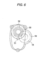
- a speed reduction mechanism 53 which contains the intermediate shaft, a gear 54 and so on is generally provided so as to protrude from a side face of a housing 50 than a motor shaft 51 and a gear 52 at an output shaft side. For this reason, an overall width is increased, and screwing work in a narrow space is restricted.
- the shift lever is further provided outside the first gear having a large diameter to perform two-step speed change, and hence, the housing becomes more large-sized, incurring deterioration of workability.
- a screw driver comprising:
- the two-step speed changing mechanism can be incorporated in the housing with space saving.
- the housing can be made compact, and the screwing work can be conducted even in a narrow space, resulting in excellent workability.
- the screw driver may further comprises: a housing, having an inner face formed with an engagement member; and an operating member, adapted to be manually operated.
- the second gear is movable in the axial direction between a first position meshed with the first gear and a second position engaged with the engagement member by the operating member.
- the second gear rotates around the rotary center together with the first gear and the planetary gears are not allowed to revolve around to revolve around the rotary center when the second gear is placed in the first position, so that the rotations of the first gear is directly transmitted to the carrier.
- the second gear is not allowed to rotate around the rotary center and the planetary gears are allowed to revolve around the rotary center when the second gear is placed in the second position, so that the rotations of the first gear is reduced and transmitted to the carrier by way of the planetary gears.
- the operating member may be a disk-shaped knob.
- the second gear may be moved between the first position and the second position by turning the knob.
- the screw driver may further comprise a pin, formed on an inner face of the knob at an eccentric position relative to a turning center of the knob.
- the pin may' be fitted with a groove formed on a circumferential face of the second gear, so that the second gear is moved in accordance with the turn of the knob.
- the screw driver may further comprise an elastic member, urging the second gear toward one of the first position and the second position.
- a part of a circumferential face of the knob may form a cam face configured to move the second gear against an urging force of the elastic member in accordance with the turn of the knob.
- the screw driver may further comprise a pin, formed on an inner face of the operating member and fitted with a groove formed on a circumferential face of the second gear.
- the second gear may be moved between the first position and the second position by moving the operating member in the axial direction.
- the two-step speed changing mechanism can be rationally constructed with enhanced space saving.
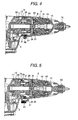
- FIG. 1 shows a screw driver according to a first embodiment of the invention.
- a screw driver 1 includes a main housing 2 which contains a motor 3 in a rear part thereof (at a left side in the drawing), and a front housing 5 which contains an output shaft 6 so as to move back and forth in an axial direction at an upper position than a motor shaft 4 of the motor 3.
- the front housing 5 is coupled to the main housing 2 at a front side thereof.
- Reference numeral 7 is a switch of the motor 3, and 8 is a trigger for turning the switch 7 ON.
- a gear housing 10 which has a cover part 11 covering a lower half part of a bearing housing 9 and a tubular part 12 formed in an upper part, a front end sleeve 13 which rotatably holds a front end of the output shaft 6, and a lock ring 14 which rotatably holds a driver bit 15 fitted with a front end of the output shaft 6 to restrict an front position of the output shaft 6.
- the front housing 5 is attached to the bearing housing 9 which rotatably holds the motor shaft 4 and a rear end of the output shaft 6.
- a stop ring 16 for adjusting a screwing depth is mounted in the front side of the lock ring 14.
- a first gear 17 meshed with the motor shaft 4 is rotatably provided on an outer periphery of a rear end of the output shaft 6, as an individual member.
- a carrier 20 which rotatably holds planetary gears 21 revolving around an output part 18 which is projected forward from the first gear 17 is rotatably provided on an outer periphery of the output shaft 6, as an individual member.
- a second gear 19 is provided in a tubular part 12 and the carrier 20 is provided at the inner side of the second gear 19.
- a clutch mechanism 22 is provided in the front side of the carrier 20.
- a movable clutch 24 is rotatably provided on an outer periphery of the output shaft 6 as an individual member and coupled to a front part of the carrier 20.
- a fixed clutch 25 is integrally fixed to the output shaft 6 in the front side of the movable clutch 24.
- Steel balls 23 are interposed between the movable clutch 24 and the carrier 20.
- Clutch claws 26 to be meshed with each other are respectively projected from opposing faces of the two clutches 24, 25.
- a coil spring 27 is interposed between the two clutches 24, 25, whereby in the ordinary state, the fixed clutch 25 is urged forward so that the fixed clutch 25 is separated from the movable clutch 24 and the front end of the output shaft 6 comes into contact with the lock ring 14.
- a bevel gear 28 formed on a front face of the fixed clutch 25 is engaged with an engaging ring 29 which is fixed to an inner face of the front end sleeve 13 thereby to restrict the rotations of the fixed clutch 25 and the output shaft 6.
- the second gear 19 can rotate inside the tubular part 12 of the gear housing 10 and can move back and forth in the axial direction (between a front position and a rear position).
- a stopper.claw 31 which can be locked to a locking part 30 formed at a rear end of the front end sleeve 13. Therefore, at the front position of the second gear 19, the rotation is restricted by lock between the stopper claw 31 and the locking part 30, as shown in Fig. 2 , thereby permitting the planetary gears 21 to revolve (low-speed mode).
- the rear position of the second gear 19 as shown in Fig.
- internal teeth of the second gear 19 are meshed with teeth 32 which are formed on an outer periphery of a front part of the first gear 17, whereby the revolution of the planetary gears 21 is restricted and the first gear 17 is directly connected to the carrier 20 (high-speed mode).
- the front and rear positions of the second gear 19 are operated by a disc-shaped knob 33 which is provided on a lower face of the tubular part 12, as an operating member. Specifically, a pin 34 which is uprightly provided at an eccentric position on an upper face of the knob 33 is engaged with a groove 35 which is formed in a circumferential direction on an outer periphery of the second gear 19.
- the second gear 19 moves back and forth according to a moving amount of the pin 34 in the front-rear direction following the turn of the knob 33.
- the second gear 19 is moved to the rear position by turning the knob 33, as shown in Fig. 1 , and the high-speed mode is selected.
- this high-speed mode when the screw driver 1 is pressed forward having a distal end of the driver bit 15 engaged with a screw head, the driver bit 15 and the output shaft 6 relatively retreat inside the front housing 5 against urging force of the coil spring 27, whereby the fixed clutch 25 is separated from the engaging ring 29 to be meshed with the movable clutch 24.
- rotation speed of the motor shaft 4 is reduced by the first gear 17, and the rotation of the first gear 17 is directly transmitted to the carrier 20.
- rotation of the carrier 20 at high speed is transmitted to the movable clutch 24 by way of the steel balls 23, and then, transmitted to the output shaft 6 and the driver bit 15 by way of the fixed clutch 25 which is integrally meshed with the movable clutch 24.
- the carrier 20 provided with the planetary gears 21 capable of revolving around the output part 18 of the first gear 17 at the inside of the second gear 19 is interposed between the first gear 17 and the clutch mechanism 22.
- the second gear 19 is provided so as to rotate at the inside of the front housing 5, and so as to move back and forth between the rear position at which it is engaged with the output part 18 to directly connect the first gear 17 to the carrier 20 and the front position at which it is separated from the output part 18 to be locked to the locking part 30 to restrict the rotation.
- the knob 33 for moving the second gear 19 between the back and forth positions is provided on the front housing 5.
- the speed reduction mechanism will not protrude from the side face, as shown in Fig. 3 , and the two-step speed changing mechanism can be incorporated with space saving. In this manner, the front housing 5 can be made compact, and hence, screwing work can be conducted even in a narrow space, resulting in excellent workability.
- the operating member for moving the second gear back and forth is not limited to the above described configuration, but the operating member may be provided on an upper face or a side face of the front housing.
- a lever 36 having a pin 37 which is engaged with the groove 35 in the second gear 19 may be provided on the lower face of the tubular part 12 so as to slide in the front-rear direction, so that the front and rear positions of the second gear 19 can be selected by operating the lever 36 back and forth.
- the second gear 19 may be urged by a coil spring 38 to the front position in which it comes into contact with a stopper 39 in the tubular part 12, while a knob 40 having a contact face (circumferential face) with the front face of the second gear 19 is rotatably fitted with a pin 41.
- the knob 40 is configured such that radius thereof varies in accordance with circumferential positions thereof so as to form a cam face.
- the contact face can move the second gear 19 rearward against urging force of the coil spring 38, and when the knob 40 is turned in an opposite direction, the second gear 19 can move forward by the urging force of the coil spring 38.
- the front housing is not limited to an assembly of a plurality of housings and sleeves as in the above described embodiment, but may be an integral body which is coupled to the main housing.
- the main housing too may be an integral body.
- manner of rotatably holding the clutch mechanism and the output shaft, and manner of mounting the driver bit etc. are not limited to the above described embodiment, but may be appropriately changed in design.
- the carrier provided with the planetary gears too is not limited to one step, but a plurality of steps may be provided coaxially.
- the second gear in either step may be provided so as to rotate and so as to move back and forth, so that it can be used for two-step speed change.
- two-step speed changing mechanism is provided.
- a screw driver which is excellent in workability while a compact housing is realized even if the two-step speed changing mechanism is omitted.
- the second gear 19 is fixed on the inner face of the front housing 5 under the state shown in Fig. 2 .
Abstract
Description
- The present invention relates to a screw driver which is used for screw fastening.
-
Japanese Patent Publication No. 1-121179A - In this screw driver, for the purpose of performing two-step speed change of the output shaft, the intermediate shaft can be operated to move back and forth by a shift lever which is provided on a lower face of the housing, and another second pinion meshed with the final gear is rotatably fitted to the intermediate shaft in the rear side of the second pinion. Specifically, when the intermediate shaft is moved forward by the shift lever, the forward second pinion is meshed with the final gear to realize low-speed rotation, and when the intermediate shaft is moved rearward, the front second pinion is meshed with the rear second pinion, whereby the final gear is rotated at high-speed by way of the rear second pinion.
- However, in the screw driver in which speed reduction is performed by providing the intermediate shaft as described above, as shown in
Fig. 6 , for example, aspeed reduction mechanism 53 which contains the intermediate shaft, agear 54 and so on is generally provided so as to protrude from a side face of ahousing 50 than amotor shaft 51 and agear 52 at an output shaft side. For this reason, an overall width is increased, and screwing work in a narrow space is restricted. Particularly, in the screw driver disclosed in the above publication, the shift lever is further provided outside the first gear having a large diameter to perform two-step speed change, and hence, the housing becomes more large-sized, incurring deterioration of workability. - It is therefore a first advantageous aspect of the invention to provide a screw driver which is excellent in workability while a compact housing is realized.
- It is a second advantageous aspect of the invention to provide a screw driver which is excellent in workability with a two-step speed changing mechanism.
- According to one aspect of the invention, there is provided a screw driver, comprising:
- a motor, having a motor shaft;
- an output shaft, provided with a driver bit and movable in an axial direction thereof;
- a first gear, configured to rotate around a rotary center to transmit rotations of the motor shaft;
- a second gear, having inner teeth;
- a carrier, including planetary gears each of which is disposed inside the second gear to mesh with the inner teeth; and
- a clutch mechanism, configured to connect or disconnect the carrier and the output shaft in accordance with the movement of the output shaft, wherein:
- the rotations of the first gear is transmitted to the carrier by way of the planetary gears.
- With this configuration, a reduction mechanism does not protrude from the side face of the housing, and the two-step speed changing mechanism can be incorporated in the housing with space saving. As the results, the housing can be made compact, and the screwing work can be conducted even in a narrow space, resulting in excellent workability.
- The screw driver may further comprises: a housing, having an inner face formed with an engagement member; and an operating member, adapted to be manually operated. Here, the second gear is movable in the axial direction between a first position meshed with the first gear and a second position engaged with the engagement member by the operating member. The second gear rotates around the rotary center together with the first gear and the planetary gears are not allowed to revolve around to revolve around the rotary center when the second gear is placed in the first position, so that the rotations of the first gear is directly transmitted to the carrier. The second gear is not allowed to rotate around the rotary center and the planetary gears are allowed to revolve around the rotary center when the second gear is placed in the second position, so that the rotations of the first gear is reduced and transmitted to the carrier by way of the planetary gears.
- The operating member may be a disk-shaped knob. The second gear may be moved between the first position and the second position by turning the knob.
- The screw driver may further comprise a pin, formed on an inner face of the knob at an eccentric position relative to a turning center of the knob. The pin may' be fitted with a groove formed on a circumferential face of the second gear, so that the second gear is moved in accordance with the turn of the knob.
- The screw driver may further comprise an elastic member, urging the second gear toward one of the first position and the second position. A part of a circumferential face of the knob may form a cam face configured to move the second gear against an urging force of the elastic member in accordance with the turn of the knob.
- The screw driver may further comprise a pin, formed on an inner face of the operating member and fitted with a groove formed on a circumferential face of the second gear. The second gear may be moved between the first position and the second position by moving the operating member in the axial direction.
- With the above configurations, the two-step speed changing mechanism can be rationally constructed with enhanced space saving.
-
-
Fig. 1 is a section view of a screw driver according to a first embodiment of the invention, showing a state to perform a high-speed mode: -
Fig. 2 is a section view of the screw driver, showing a state to perform a low-speed mode. -
Fig. 3 is a schematic front view of the screw driver. -
Fig. 4 is a section view of a screw driver according to a second embodiment of the invention. -
Fig. 5 is a section view of a screw driver according to a third embodiment of the invention. -
Fig. 6 is a schematic front view of a related-art screwdriver. - Embodiments of the invention will be described below in detail with reference to the accompanying drawings.
-
Fig. 1 shows a screw driver according to a first embodiment of the invention. A screw driver 1 includes amain housing 2 which contains amotor 3 in a rear part thereof (at a left side in the drawing), and afront housing 5 which contains anoutput shaft 6 so as to move back and forth in an axial direction at an upper position than amotor shaft 4 of themotor 3. Thefront housing 5 is coupled to themain housing 2 at a front side thereof.Reference numeral 7 is a switch of themotor switch 7 ON. - In the
front housing 5, agear housing 10 which has acover part 11 covering a lower half part of a bearinghousing 9 and atubular part 12 formed in an upper part, afront end sleeve 13 which rotatably holds a front end of theoutput shaft 6, and alock ring 14 which rotatably holds adriver bit 15 fitted with a front end of theoutput shaft 6 to restrict an front position of theoutput shaft 6. Thefront housing 5 is attached to the bearinghousing 9 which rotatably holds themotor shaft 4 and a rear end of theoutput shaft 6. Astop ring 16 for adjusting a screwing depth is mounted in the front side of thelock ring 14. - Moreover, inside the
gear housing 10, afirst gear 17 meshed with themotor shaft 4 is rotatably provided on an outer periphery of a rear end of theoutput shaft 6, as an individual member. In the front side of thefirst gear 17, acarrier 20 which rotatably holdsplanetary gears 21 revolving around anoutput part 18 which is projected forward from thefirst gear 17 is rotatably provided on an outer periphery of theoutput shaft 6, as an individual member. Asecond gear 19 is provided in atubular part 12 and thecarrier 20 is provided at the inner side of thesecond gear 19. Aclutch mechanism 22 is provided in the front side of thecarrier 20. - In the
clutch mechanism 22 having a known structure, amovable clutch 24 is rotatably provided on an outer periphery of theoutput shaft 6 as an individual member and coupled to a front part of thecarrier 20. Afixed clutch 25 is integrally fixed to theoutput shaft 6 in the front side of themovable clutch 24.Steel balls 23 are interposed between themovable clutch 24 and thecarrier 20.Clutch claws 26 to be meshed with each other are respectively projected from opposing faces of the twoclutches clutches fixed clutch 25 is urged forward so that thefixed clutch 25 is separated from themovable clutch 24 and the front end of theoutput shaft 6 comes into contact with thelock ring 14. In this state, abevel gear 28 formed on a front face of the fixedclutch 25 is engaged with anengaging ring 29 which is fixed to an inner face of thefront end sleeve 13 thereby to restrict the rotations of thefixed clutch 25 and theoutput shaft 6. - In this structure, the
second gear 19 can rotate inside thetubular part 12 of thegear housing 10 and can move back and forth in the axial direction (between a front position and a rear position). On a front end face of thesecond gear 19, there is formed astopper.claw 31 which can be locked to a lockingpart 30 formed at a rear end of thefront end sleeve 13. Therefore, at the front position of thesecond gear 19, the rotation is restricted by lock between thestopper claw 31 and thelocking part 30, as shown inFig. 2 , thereby permitting theplanetary gears 21 to revolve (low-speed mode). On the other hand, at the rear position of thesecond gear 19 as shown inFig. 1 , internal teeth of thesecond gear 19 are meshed withteeth 32 which are formed on an outer periphery of a front part of thefirst gear 17, whereby the revolution of theplanetary gears 21 is restricted and thefirst gear 17 is directly connected to the carrier 20 (high-speed mode). The front and rear positions of thesecond gear 19 are operated by a disc-shaped knob 33 which is provided on a lower face of thetubular part 12, as an operating member. Specifically, apin 34 which is uprightly provided at an eccentric position on an upper face of theknob 33 is engaged with agroove 35 which is formed in a circumferential direction on an outer periphery of thesecond gear 19. Thesecond gear 19 moves back and forth according to a moving amount of thepin 34 in the front-rear direction following the turn of theknob 33. - In the screw driver 1 having the above described structure, the
second gear 19 is moved to the rear position by turning theknob 33, as shown inFig. 1 , and the high-speed mode is selected. In this high-speed mode, when the screw driver 1 is pressed forward having a distal end of thedriver bit 15 engaged with a screw head, thedriver bit 15 and theoutput shaft 6 relatively retreat inside thefront housing 5 against urging force of the coil spring 27, whereby the fixed clutch 25 is separated from the engagingring 29 to be meshed with themovable clutch 24. In this state, by operating thetrigger 8 to actuate themotor 3, rotation speed of themotor shaft 4 is reduced by thefirst gear 17, and the rotation of thefirst gear 17 is directly transmitted to thecarrier 20. As the results, rotation of thecarrier 20 at high speed is transmitted to the movable clutch 24 by way of thesteel balls 23, and then, transmitted to theoutput shaft 6 and thedriver bit 15 by way of the fixed clutch 25 which is integrally meshed with themovable clutch 24. - On the other hand, when the
motor 3 is actuated in a state that thesecond gear 19 is moved to the front position to select the low-speed mode by turning theknob 33 as shown inFig. 2 , the rotation speed of themotor shaft 4 is reduced by thefirst gear 17, and transmitted to thecarrier 20, after the speed has been further reduced through revolution of theplanetary gears 21 at the inside of thesecond gear 19 following rotation of theoutput part 18 of thefirst gear 17. As the results, the rotation of thecarrier 20 at low speed is transmitted to the movable clutch 24 by way of thesteel balls 23, and further transmitted to theoutput shaft 6 and thedriver bit 15 by way of the fixedclutch 25. - In both the high-speed mode and the low-speed mode, as the screwing operation proceeds, the screw driver 1 moves forward. When the
stop ring 16 comes into contact with a face to be screwed in, forward movement of the screw driver 1 will stop, and only theoutput shaft 6 moves forward while the screwing operation is continued. The fixed clutch 25 is separated from the movable clutch 24 by this forward movement at the final screwing, whereby the rotation of theoutput shaft 6 will stop. - As described the above, the
carrier 20 provided with theplanetary gears 21 capable of revolving around theoutput part 18 of thefirst gear 17 at the inside of thesecond gear 19 is interposed between thefirst gear 17 and theclutch mechanism 22. Thesecond gear 19 is provided so as to rotate at the inside of thefront housing 5, and so as to move back and forth between the rear position at which it is engaged with theoutput part 18 to directly connect thefirst gear 17 to thecarrier 20 and the front position at which it is separated from theoutput part 18 to be locked to the lockingpart 30 to restrict the rotation. Theknob 33 for moving thesecond gear 19 between the back and forth positions is provided on thefront housing 5. As the results, the speed reduction mechanism will not protrude from the side face, as shown inFig. 3 , and the two-step speed changing mechanism can be incorporated with space saving. In this manner, thefront housing 5 can be made compact, and hence, screwing work can be conducted even in a narrow space, resulting in excellent workability. - Moreover, since the
second gear 19 is moved back and forth by turning the disk-shapedknob 33, it is possible to rationally construct the two-step speed changing mechanism with enhanced space saving. - The operating member for moving the second gear back and forth is not limited to the above described configuration, but the operating member may be provided on an upper face or a side face of the front housing.
- Alternatively, according to a second embodiment of the invention as shown in
Fig. 4 , alever 36 having apin 37 which is engaged with thegroove 35 in thesecond gear 19 may be provided on the lower face of thetubular part 12 so as to slide in the front-rear direction, so that the front and rear positions of thesecond gear 19 can be selected by operating thelever 36 back and forth. - Further, according to a third embodiment of the invention as shown in
Fig. 5 , thesecond gear 19 may be urged by acoil spring 38 to the front position in which it comes into contact with a stopper 39 in thetubular part 12, while aknob 40 having a contact face (circumferential face) with the front face of thesecond gear 19 is rotatably fitted with apin 41. Theknob 40 is configured such that radius thereof varies in accordance with circumferential positions thereof so as to form a cam face. Thus, in accordance with the turn of theknob 40, the contact face can move thesecond gear 19 rearward against urging force of thecoil spring 38, and when theknob 40 is turned in an opposite direction, thesecond gear 19 can move forward by the urging force of thecoil spring 38. - Besides, the front housing is not limited to an assembly of a plurality of housings and sleeves as in the above described embodiment, but may be an integral body which is coupled to the main housing. The main housing too may be an integral body.
- Moreover, manner of rotatably holding the clutch mechanism and the output shaft, and manner of mounting the driver bit etc. are not limited to the above described embodiment, but may be appropriately changed in design. The carrier provided with the planetary gears too is not limited to one step, but a plurality of steps may be provided coaxially. In this case, the second gear in either step may be provided so as to rotate and so as to move back and forth, so that it can be used for two-step speed change.
- In the above embodiments, two-step speed changing mechanism is provided. However, it is possible to attain the advantageous aspect that a screw driver which is excellent in workability while a compact housing is realized even if the two-step speed changing mechanism is omitted. In such a configuration, the
second gear 19 is fixed on the inner face of thefront housing 5 under the state shown inFig. 2 . - Although only some exemplary embodiments of the invention have been described in detail above, those skilled in the art will readily appreciated that many modifications are possible in the exemplary embodiments without materially departing from the novel teachings and advantages of the invention. Accordingly, all such modifications are intended to be included within the scope of the invention.
- It is explicitly stated that all features disclosed in the description and/or the claims are intended to be disclosed separately and independently from each other for the purpose of original disclosure as well as for the purpose of restricting the claimed invention independent of the composition of the features in the embodiments and/or the claims. It is explicitly stated that all value ranges or indications of groups of entities disclose every possible intermediate value or intermediate entity for the purpose of original disclosure as well as for the purpose of restricting the claimed invention, in particular as limits of value ranges.
Claims (6)
- A screw driver, comprising:a motor, having a motor shaft;an output shaft, adapted for receiving a driver bit and movable in an axial direction thereof;a first gear, configured to rotate around a rotary center to transmit rotations of the motor shaft;a second gear, having inner teeth;a carrier, including planetary gears each of which is disposed inside the second gear to mesh with the inner teeth; anda clutch mechanism, configured to connect or disconnect the carrier and the output shaft in accordance with the movement of the output shaft,wherein:the rotations of the first gear is transmitted to the carrier by way of the planetary gears.
- The screw driver as set forth in claim 1, further comprising:a housing, having an inner face formed with an engagement member; andan operating member, adapted to be manually operated, wherein:the second gear is movable in the axial direction between a first position meshed with the first gear and a second position engaged with the engagement member by the operating member;the second gear rotates around the rotary center together with the first gear and the planetary gears are not allowed to revolve around to revolve around the rotary center when the second gear is placed in the first position, so that the rotations of the first gear is directly transmitted to the carrier; andthe second gear is not allowed to rotate around the rotary center and the planetary gears are allowed to revolve around the rotary center when the second gear is placed in the second position, so that the rotations of the first gear is reduced and transmitted to the carrier by way of the planetary gears.
- The screw driver as set forth in claim 2, wherein:the operating member is a disk-shaped knob; andthe second gear is moved between the first position and the second position by turning the knob.
- The screw driver as set forth in claim 3, further comprising:a pin, formed on an inner face of the knob at an eccentric position relative to a turning center of the knob; andthe pin is fitted with a groove formed on a circumferential face of the second gear, so that the second gear is moved in accordance with the turn of the knob.
- The screw driver as set forth in claim 3, further comprising:an elastic member, urging the second gear toward one of the first position and the second position; anda part of a circumferential face of the knob forms a cam face configured to move the second gear against an urging force of the elastic member in accordance with the turn of the knob.
- The screw driver as set forth in claim 2, further comprising:a pin, formed on an inner face of the operating member and fitted with a groove formed on a circumferential face of the second gear; andthe second gear is moved between the first position and the second position by moving the operating member in the axial direction.
Applications Claiming Priority (1)
| Application Number | Priority Date | Filing Date | Title |
|---|---|---|---|
| JP2006334908A JP5064780B2 (en) | 2006-12-12 | 2006-12-12 | Screw driver |
Publications (2)
| Publication Number | Publication Date |
|---|---|
| EP1932622A2 true EP1932622A2 (en) | 2008-06-18 |
| EP1932622A3 EP1932622A3 (en) | 2009-09-09 |
Family
ID=39106201
Family Applications (1)
| Application Number | Title | Priority Date | Filing Date |
|---|---|---|---|
| EP07024109A Withdrawn EP1932622A3 (en) | 2006-12-12 | 2007-12-12 | Screwdriver with motor and speed change mechanism |
Country Status (4)
| Country | Link |
|---|---|
| US (1) | US20080134840A1 (en) |
| EP (1) | EP1932622A3 (en) |
| JP (1) | JP5064780B2 (en) |
| CN (1) | CN101200056A (en) |
Cited By (1)
| Publication number | Priority date | Publication date | Assignee | Title |
|---|---|---|---|---|
| US11439067B2 (en) | 2019-09-10 | 2022-09-13 | Deere & Company | Shifting device for transmission having shifting device and harvesting machine |
Families Citing this family (12)
| Publication number | Priority date | Publication date | Assignee | Title |
|---|---|---|---|---|
| WO2012010093A1 (en) * | 2010-07-20 | 2012-01-26 | 苏州宝时得电动工具有限公司 | Power tool |
| CN102335908B (en) * | 2010-07-20 | 2014-04-16 | 苏州宝时得电动工具有限公司 | Power tool |
| CN102335907B (en) * | 2010-07-20 | 2014-04-16 | 苏州宝时得电动工具有限公司 | Power tool |
| CN102335909B (en) * | 2010-07-20 | 2014-04-16 | 苏州宝时得电动工具有限公司 | Power tool |
| CN102335906B (en) * | 2010-07-20 | 2014-04-16 | 苏州宝时得电动工具有限公司 | Power tool |
| CN102335904B (en) * | 2010-07-20 | 2014-04-16 | 苏州宝时得电动工具有限公司 | Power tool |
| US9339938B2 (en) | 2010-10-08 | 2016-05-17 | Milwaukee Electric Tool Corporation | Powered cutting tool |
| RU2013129992A (en) * | 2010-12-02 | 2015-01-10 | Макита Корпорейшн | DRIVING TOOL |
| DE102011055869A1 (en) * | 2011-11-30 | 2013-06-06 | Röhm Gmbh | drilling |
| USD668922S1 (en) | 2012-01-20 | 2012-10-16 | Milwaukee Electric Tool Corporation | Powered cutting tool |
| WO2015024530A1 (en) * | 2013-08-23 | 2015-02-26 | 苏州宝时得电动工具有限公司 | Power tool |
| JP6235872B2 (en) * | 2013-11-07 | 2017-11-22 | 株式会社マキタ | Work tools |
Citations (5)
| Publication number | Priority date | Publication date | Assignee | Title |
|---|---|---|---|---|
| DE3538121A1 (en) * | 1985-10-26 | 1987-04-30 | Licentia Gmbh | Electric tool with a two-speed gear |
| JPS62224584A (en) * | 1986-03-25 | 1987-10-02 | 松下電工株式会社 | Power tool |
| JPH01121179A (en) * | 1987-10-30 | 1989-05-12 | Hitachi Koki Co Ltd | Electric driver |
| DE19927487A1 (en) * | 1998-06-17 | 2000-01-05 | Makita Corp | Power tool, e.g. electric screw driver or power drill |
| EP1033204A2 (en) * | 1999-03-01 | 2000-09-06 | Makita Corporation | Screw drivers |
Family Cites Families (7)
| Publication number | Priority date | Publication date | Assignee | Title |
|---|---|---|---|---|
| DE7141263U (en) * | 1971-11-02 | 1973-04-19 | Bosch R Gmbh | POWER TOOL IN PARTICULAR ELECTRIC IMPACT DRILL |
| US4161242A (en) * | 1977-06-15 | 1979-07-17 | Black & Decker Inc. | Power-driven drill and screwdriver |
| JPH0657393B2 (en) * | 1989-04-20 | 1994-08-03 | 松下電工株式会社 | Screw tightening depth adjustment device for rotary tools |
| US5025903A (en) * | 1990-01-09 | 1991-06-25 | Black & Decker Inc. | Dual mode rotary power tool with adjustable output torque |
| US5524512A (en) * | 1994-03-11 | 1996-06-11 | Ryobi Motor Products Corp. | Drywall screwdriver depth adjustment |
| US6676557B2 (en) * | 2001-01-23 | 2004-01-13 | Black & Decker Inc. | First stage clutch |
| JP4291179B2 (en) * | 2004-03-10 | 2009-07-08 | 株式会社マキタ | Impact driver |
-
2006
- 2006-12-12 JP JP2006334908A patent/JP5064780B2/en not_active Expired - Fee Related
-
2007
- 2007-10-10 CN CNA2007101801454A patent/CN101200056A/en active Pending
- 2007-12-12 EP EP07024109A patent/EP1932622A3/en not_active Withdrawn
- 2007-12-12 US US12/000,410 patent/US20080134840A1/en not_active Abandoned
Patent Citations (5)
| Publication number | Priority date | Publication date | Assignee | Title |
|---|---|---|---|---|
| DE3538121A1 (en) * | 1985-10-26 | 1987-04-30 | Licentia Gmbh | Electric tool with a two-speed gear |
| JPS62224584A (en) * | 1986-03-25 | 1987-10-02 | 松下電工株式会社 | Power tool |
| JPH01121179A (en) * | 1987-10-30 | 1989-05-12 | Hitachi Koki Co Ltd | Electric driver |
| DE19927487A1 (en) * | 1998-06-17 | 2000-01-05 | Makita Corp | Power tool, e.g. electric screw driver or power drill |
| EP1033204A2 (en) * | 1999-03-01 | 2000-09-06 | Makita Corporation | Screw drivers |
Cited By (1)
| Publication number | Priority date | Publication date | Assignee | Title |
|---|---|---|---|---|
| US11439067B2 (en) | 2019-09-10 | 2022-09-13 | Deere & Company | Shifting device for transmission having shifting device and harvesting machine |
Also Published As
| Publication number | Publication date |
|---|---|
| EP1932622A3 (en) | 2009-09-09 |
| JP5064780B2 (en) | 2012-10-31 |
| JP2008142862A (en) | 2008-06-26 |
| US20080134840A1 (en) | 2008-06-12 |
| CN101200056A (en) | 2008-06-18 |
Similar Documents
| Publication | Publication Date | Title |
|---|---|---|
| EP1932622A2 (en) | Screwdriver with motor and speed change mechanism | |
| US8485275B2 (en) | Power tool | |
| EP1574294B1 (en) | Impact driver | |
| JP4227028B2 (en) | Screwdriver drill | |
| JP4468786B2 (en) | Impact tools | |
| JP4673118B2 (en) | Hammer drill equipment | |
| CN102909682B (en) | Electric power tool with vibration mechanism | |
| JP3963323B2 (en) | Electric tool | |
| CA2635861C (en) | Multi-speed drill and chuck assembly | |
| EP2103390A2 (en) | Electric power tool with switching member for selecting one operation mode among various operation modes | |
| US9283667B2 (en) | Power tool with torque clutch | |
| US20120255754A1 (en) | Percussion driver drill | |
| JPH0539814U (en) | Power transmission mechanism for rotary power tools | |
| US9434038B2 (en) | Shifting mechanism for a drill press | |
| US20070281822A1 (en) | Electric hand tool device | |
| WO2009027821A2 (en) | Power tool and transmission mechanism | |
| EP2138273B1 (en) | Rotary tool having a manual ratchet mechanism | |
| EP1941974A1 (en) | Power hand tool | |
| JP4132005B2 (en) | Electric tool | |
| JP2001088052A (en) | Rotary tool with impact mechanism | |
| JPH0679509A (en) | Drill chisel device | |
| EP0626310B1 (en) | Drive transmission system for vessel propulsion device | |
| JP4085747B2 (en) | Vibration drill driver | |
| JP3669561B2 (en) | Rotary tool with hydraulic impact mechanism | |
| JP2002046007A (en) | Power tool |
Legal Events
| Date | Code | Title | Description |
|---|---|---|---|
| PUAI | Public reference made under article 153(3) epc to a published international application that has entered the european phase |
Free format text: ORIGINAL CODE: 0009012 |
|
| AK | Designated contracting states |
Kind code of ref document: A2 Designated state(s): AT BE BG CH CY CZ DE DK EE ES FI FR GB GR HU IE IS IT LI LT LU LV MC MT NL PL PT RO SE SI SK TR |
|
| AX | Request for extension of the european patent |
Extension state: AL BA HR MK RS |
|
| PUAL | Search report despatched |
Free format text: ORIGINAL CODE: 0009013 |
|
| AK | Designated contracting states |
Kind code of ref document: A3 Designated state(s): AT BE BG CH CY CZ DE DK EE ES FI FR GB GR HU IE IS IT LI LT LU LV MC MT NL PL PT RO SE SI SK TR |
|
| AX | Request for extension of the european patent |
Extension state: AL BA HR MK RS |
|
| AKX | Designation fees paid | ||
| STAA | Information on the status of an ep patent application or granted ep patent |
Free format text: STATUS: THE APPLICATION IS DEEMED TO BE WITHDRAWN |
|
| 18D | Application deemed to be withdrawn |
Effective date: 20100310 |
|
| REG | Reference to a national code |
Ref country code: DE Ref legal event code: 8566 |