EP1932553A2 - Filter cartridge assemblies and method of filtering fluids - Google Patents
Filter cartridge assemblies and method of filtering fluids Download PDFInfo
- Publication number
- EP1932553A2 EP1932553A2 EP08002861A EP08002861A EP1932553A2 EP 1932553 A2 EP1932553 A2 EP 1932553A2 EP 08002861 A EP08002861 A EP 08002861A EP 08002861 A EP08002861 A EP 08002861A EP 1932553 A2 EP1932553 A2 EP 1932553A2
- Authority
- EP
- European Patent Office
- Prior art keywords
- section
- tubular housing
- filter media
- filter
- assembly
- Prior art date
- Legal status (The legal status is an assumption and is not a legal conclusion. Google has not performed a legal analysis and makes no representation as to the accuracy of the status listed.)
- Granted
Links
Images


Classifications
-
- B—PERFORMING OPERATIONS; TRANSPORTING
- B01—PHYSICAL OR CHEMICAL PROCESSES OR APPARATUS IN GENERAL
- B01D—SEPARATION
- B01D24/00—Filters comprising loose filtering material, i.e. filtering material without any binder between the individual particles or fibres thereof
- B01D24/007—Filters comprising loose filtering material, i.e. filtering material without any binder between the individual particles or fibres thereof with multiple filtering elements in series connection
- B01D24/008—Filters comprising loose filtering material, i.e. filtering material without any binder between the individual particles or fibres thereof with multiple filtering elements in series connection arranged concentrically or coaxially
-
- A—HUMAN NECESSITIES
- A61—MEDICAL OR VETERINARY SCIENCE; HYGIENE
- A61M—DEVICES FOR INTRODUCING MEDIA INTO, OR ONTO, THE BODY; DEVICES FOR TRANSDUCING BODY MEDIA OR FOR TAKING MEDIA FROM THE BODY; DEVICES FOR PRODUCING OR ENDING SLEEP OR STUPOR
- A61M1/00—Suction or pumping devices for medical purposes; Devices for carrying-off, for treatment of, or for carrying-over, body-liquids; Drainage systems
- A61M1/14—Dialysis systems; Artificial kidneys; Blood oxygenators ; Reciprocating systems for treatment of body fluids, e.g. single needle systems for hemofiltration or pheresis
- A61M1/16—Dialysis systems; Artificial kidneys; Blood oxygenators ; Reciprocating systems for treatment of body fluids, e.g. single needle systems for hemofiltration or pheresis with membranes
- A61M1/1694—Dialysis systems; Artificial kidneys; Blood oxygenators ; Reciprocating systems for treatment of body fluids, e.g. single needle systems for hemofiltration or pheresis with membranes with recirculating dialysing liquid
- A61M1/1696—Dialysis systems; Artificial kidneys; Blood oxygenators ; Reciprocating systems for treatment of body fluids, e.g. single needle systems for hemofiltration or pheresis with membranes with recirculating dialysing liquid with dialysate regeneration
-
- A—HUMAN NECESSITIES
- A61—MEDICAL OR VETERINARY SCIENCE; HYGIENE
- A61M—DEVICES FOR INTRODUCING MEDIA INTO, OR ONTO, THE BODY; DEVICES FOR TRANSDUCING BODY MEDIA OR FOR TAKING MEDIA FROM THE BODY; DEVICES FOR PRODUCING OR ENDING SLEEP OR STUPOR
- A61M2206/00—Characteristics of a physical parameter; associated device therefor
- A61M2206/10—Flow characteristics
- A61M2206/11—Laminar flow
-
- B—PERFORMING OPERATIONS; TRANSPORTING
- B01—PHYSICAL OR CHEMICAL PROCESSES OR APPARATUS IN GENERAL
- B01D—SEPARATION
- B01D2201/00—Details relating to filtering apparatus
- B01D2201/44—Special measures allowing the even or uniform distribution of fluid along the length of a conduit
-
- C—CHEMISTRY; METALLURGY
- C02—TREATMENT OF WATER, WASTE WATER, SEWAGE, OR SLUDGE
- C02F—TREATMENT OF WATER, WASTE WATER, SEWAGE, OR SLUDGE
- C02F1/00—Treatment of water, waste water, or sewage
- C02F1/28—Treatment of water, waste water, or sewage by sorption
- C02F1/281—Treatment of water, waste water, or sewage by sorption using inorganic sorbents
-
- C—CHEMISTRY; METALLURGY
- C02—TREATMENT OF WATER, WASTE WATER, SEWAGE, OR SLUDGE
- C02F—TREATMENT OF WATER, WASTE WATER, SEWAGE, OR SLUDGE
- C02F1/00—Treatment of water, waste water, or sewage
- C02F1/28—Treatment of water, waste water, or sewage by sorption
- C02F1/283—Treatment of water, waste water, or sewage by sorption using coal, charred products, or inorganic mixtures containing them
-
- C—CHEMISTRY; METALLURGY
- C02—TREATMENT OF WATER, WASTE WATER, SEWAGE, OR SLUDGE
- C02F—TREATMENT OF WATER, WASTE WATER, SEWAGE, OR SLUDGE
- C02F1/00—Treatment of water, waste water, or sewage
- C02F1/42—Treatment of water, waste water, or sewage by ion-exchange
-
- C—CHEMISTRY; METALLURGY
- C02—TREATMENT OF WATER, WASTE WATER, SEWAGE, OR SLUDGE
- C02F—TREATMENT OF WATER, WASTE WATER, SEWAGE, OR SLUDGE
- C02F2201/00—Apparatus for treatment of water, waste water or sewage
- C02F2201/002—Construction details of the apparatus
- C02F2201/006—Cartridges
Definitions
- the present invention relates to filter cartridges and methods for filtering fluids.
- Filter cartridges are used in many applications, including medical devices. In the medical field, filter cartridges containing certain powdered filter media are used. One application for such a filter cartridge is in a dialysis system.
- the United States patent US 2,328,381 discloses a pipe joint.
- a compact biofilter for drinking water treatment is disclosed in the United States patent US 5,032,261 .
- a plastic media filter is disclosed in the United States patent US 5,350,505 .
- the United States patent US 3,357,563 discloses an apparatus for treating water.
- a cartridge useful for cleaning dialysis solutions is disclosed in United States patent application US 2002/0112609 , which was published after the priority date of the current application.
- the patent specifications of UK 1,470,206 discloses a dialyser.
- a recirculation dialysate system for use with an artificial kidney machine is disclosed in the United States patent US 3,669,880 .
- Systems for patients requiring hemodialysis or peritoneal dialysis can involve pumping a large volume of dialysate through a dialyzing device.
- the used dialysate is generally discarded after a single passing.
- More recent embodiments of dialysis devices involve pumping a fixed volume of dialysate through a dialyzing device, whereupon the used dialysate flows through a filter cartridge and is then returned to a dialysate reservoir for reuse. Flow through the cartridge, however, does not optimize filtering of the dialysate through various granular filtering media.
- the flow of a fluid through a filter cartridge having filter media sections of varying granule diameters takes different directional flow paths through the respective sections. As a result, fluid flow through a powdered medium containing large diameter granules disposed in a filter cartridge is laminar. Fluid flow through a powdered filter medium containing small diameter granules disposed in a filter cartridge is not laminar and results in a condition known as wicking.
- Wicking occurs when the fluid generally flows in the direction of areas of least pressure, which tend to be areas between the inner wall of the tubular housing and the powdered filter medium. Wicking results in the fluid bypassing the majority of the surface area of the granular filter medium. As a result, filtering is inefficient.
- a filter cartridge assembly of generally cylindrical shape includes a tubular housing having an inner wall, a first end, a second end, and a plurality of annular flow deflectors that extend radially inwardly from the inner wall of the tubular housing to focus the flow of fluid through the center of the filter media in the cartridge.
- the inner wall is of constant diameter.
- a first connector is adapted to seal the first end except at an entrance port where fluid can enter the filter cartridge.
- a second connector is adapted to seal the second end except at the exit port where fluid can exit the filter cartridge.
- Powdered filter media for performing many different filtering functions can be used.
- the different media can cause different reactions, including enzymatic decomposition, cation exchange, anion exchange, or chemical adsorption.
- the various filter media can consist of different sized and shaped granular or powdered insoluble chemicals that have different physical and chemical characteristics.
- a filter cartridge assembly is provided according to any one of the embodiments listed herein, and a fluid is flowed through or circulated through the filter cartridge by a fluid circulating device, a pump, gravity, or a gravity column.
- the present invention overcomes the problems of the prior art by providing a filter cartridge assembly of simple construction and that efficiently filters fluids.
- the filter cartridge assembly of the present invention can advantageously be less costly to manufacture than conventional filter cartridges and can be employed in recirculating systems.
- the filter cartridge assembly of the present invention is also less costly to use than conventional filter cartridges because it is more efficient at filtering fluid per unit volume of filter media.
- the present invention is also directed to filter cartridge assemblies including various powdered filtered media contained therein.
- the various powdered filter media can include those media described in U.S. Patent Application No. 09/996,505 to Wong , filed concurrently with the present application and entitled “Cartridges Useful in Cleaning Dialysis Solutions” and published as US2002/0112609 A1 .
- a filter cartridge assembly includes a tubular housing having an inner wall, a first end, a second end, and at least three sections having progressively smaller average inner diameters in a direction from the first end to the second end.
- a first connector is adapted to seal the first end except at an entrance port where fluid can enter the cartridge.
- a second connector is adapted to seal the second end except at an exit port where fluid can exit the cartridge.
- the inner wall of the tubular housing is provided with shoulders at the intersections of the respective sections. The shoulders deflect the flow of fluid from the outer periphery of the filter media to paths that flow through the center of the filter media.
- FIG. 1 Another filter cartridge assembly of conical shape is provided that includes a tubular housing having an inner wall, a first end, a second end, and a plurality of annular flow deflectors that extend radially inwardly from the inner wall of the tubular housing.
- conical what is meant is generally conical, preferably perfectly conical, and more preferably having a continuously decreasing inner diameter defined by the inner wall regardless of the shape of the outside of the filter cartridge.
- the annular flow deflectors can be integrally formed or molded with the inner wall of the tubular housing or attached, mounted, fixed, or positioned on the inner wall of the tubular housing by a compression fit, threaded engagement, by snapping in a groove, or by other means.
- annular flow deflectors can be held in place by filter media in a tightly packed, compressed, or settled form.
- a first connector is adapted to seal the first end except at an entrance port where fluid can enter the filter cartridge.
- a second connector is adapted to seal the second end except at an exit port where fluid can exit the filter cartridge.
- the inner wall of the tubular housing is continuously tapering in a direction from the first end to the second end.
- a filter cartridge assembly having a cylindrical shape includes a tubular housing having an inner wall, a first end, a second end, and a plurality of annular flow deflectors that extend radially inwardly from the inner wall.
- cylindrical what is meant is generally cylindrical, preferably perfectly cylindrical, more preferably having a constant inner diameter defined by the inner wall regardless of the shape of the outside of the filter cartridge.
- the annular flow deflectors can be integrally formed or molded with the inner wall of the tubular housing or attached, mounted, fixed, or positioned on the inner wall of the tubular housing by a compression fit, threaded engagement, by snapping in a groove or by other means.
- annular flow deflectors can be held in place by filter media in a tightly packed, compressed, or settled form.
- a first connector is adapted to seal the first end except at an entrance port where fluid can enter the filter cartridge.
- a second connector is adapted to seal the second end except at an exit port where fluid can exit the filter cartridge.
- any of the filter cartridge assemblies of the present invention can be used in a recirculating system to filter a recirculating fluid.
- the diameter of the inner wall of the tubular housing can be modulated to regulate pressure and the flow rate.
- the diameter of the inner wall for example, from about 4 to about 7 inches, can result in a flow rate of, for example, from about 150 ml/min to about 500 ml/min at a pressure of less than or equal to, for example, about 172,4 kPa (pounds per square inch).
- Some filter media for example, activated carbon, have relatively large granules (coarse media), for example, with diameters of from about 425 micrometers to about 1,700 micrometers.
- Some filter media for example, zirconium phosphate or alumina, have relatively small granules (fine media), for example, having diameters of from about 20 micrometers to about 100 micrometers, e.g. from about 45 micrometers to about 100 micrometers.
- the annular flow deflectors are attached to the inner wall of the tubular housing within a section of a filter medium.
- the extent that the annular flow deflector extends into the housing from the inner wall is preferably from about 1.0 percent to 5.0 percent of the diameter of the inner wall at the flow deflector. If the width of the concentric surface of the annular flow deflector is too great, utilization of the filter medium behind the annular flow deflector is lower than the average utilization of the filter medium. If the width of the concentric surface of the annular flow deflector is too little, deflection of the fluid may not result in laminar flow and wicking occurs.
- An embodiment of the present invention includes a first connector and a second connector adapted to seal the first end and the second end, respectively.
- the first connector and the second connector can be hermetically sealed to the first end and the second end using, for example, a variety of conventional sealing techniques, such as, but not limited to, EMABOND, Ashland Specialty Chemical Company, a division of Ashland, Inc., Columbus, Ohio, or another sealing composition or method such as ultrasound, heat, chemical bonding, vibration, physical latch, or gasket.
- the sealing method preferably is capable of withstanding moderate pressures of greater than 275,8 kPa (40 pounds per square inch).
- the entrance port and exit port of the filter cartridge assembly are connected to a fluid recirculating or pumping system.
- the fluid recirculating system can be, for example, a dialysis machine, including a portable dialysis machine.
- the fluid recirculating system can include, for example, a fluid pump, a dialyzing device, and a fluid reservoir.
- a filter medium seal is inserted into one of the first end and the second end of the tubular housing.
- the filter medium seal or part thereof can be a filter paper, a filter pad, a first connector, and a second connector. Many seals can be used.
- Each filter medium seal is preferably disk-shaped and preferably has an outer periphery that matches the inner periphery of the tubular housing at the location of the seal within the tubular body.
- a filter medium is introduced into the tubular housing to form a part of or an entire filter medium section, and the filter medium is subsequently settled as by vibrating, packing, shaking, jogging, compressing, or otherwise increasing the density of the filter medium section.
- the other of the first and second ends of the tubular housing is sealed with another filter medium seal to contain the filter medium section and maintain the density of the filter medium section.
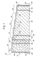
- Fig.1 is a cross-sectional view of half of a filter cartridge assembly 100 wherein the end connectors are removed.
- the other half of the cartridge cross-section (not shown) is a mirror image of the cartridge half cross-section shown, along centerline 102 of Fig.1 .
- the cartridge 100 includes a tubular housing 104 having an inner wall 106 and an outer wall 108.
- the tubular housing 104 has, by way of example, five sections 110, 112, 114, 116, and 118.
- the sections have lengths having progressively smaller average inner diameters in a direction from a first end 115 to a second end 125 of the tubular housing 104.
- the inner wall 106 of the tubular housing 104 is provided with shoulders 120, 122, 124, and 126 at the intersections between the respective adjacent sections of the tubular housing. Each shoulder acts as an annular flow deflector extending radially inwardly from the inner wall 106.
- a first end cap or connector (not shown) is adapted to seal the first end 115 of the cartridge 100 except at an entrance port where fluid can enter the cartridge.
- a second end cap or connector (not shown) is adapted to seal the second end 125 except at an exit port where fluid can exit the cartridge. Details of the first and second connectors are shown in Figs. 4-6 .
- Sections of various filter media are contained within the tubular housing 104.
- at least one filter medium section spans portions of at least two lengths of inner wall sections110, 112, 114, 116, and 118 such that the filter medium section traverses a shoulder 120, 122, 124, or 126.
- Thick, porous filter pads 130, 132, and 134 can be used to contain filter media within the tubular housing 104 or can be used to maintain separation between two adjacent filter media sections, for example, between granular filter media sections having different and widely disparate average granule diameters.
- Thinner, porous filter paper 136, 138, and 140 can be used, for example, to maintain separation between two adjacent granular filter media sections having similar average granule diameters.
- the filter pads 130, 132, and 134, and the filter papers 136, 138, and 140 are each preferably disk-shaped and each preferably has an outer periphery that matches the inner periphery of the tubular housing 104 at the location of the respective pad or paper within the tubular housing 104.
- the various filter media sections within the tubular housing 104 can include, as shown, a granular activated carbon section 142, an immobilized enzyme section 144, a powdered alumina (Al 2 O 3 ) section 146, a zirconium phosphate section 148, and a section 150 that includes a mixture of hydrous zirconium oxide of the acetate form and sodium zirconium carbonate.
- Fig. 2 is a cross-sectional view of half of a filter cartridge 200 wherein the end connectors are removed.
- the other half of the cartridge cross-section (not shown) is a mirror image of the cartridge half cross-section shown, along centerline 202 of Fig. 2 .
- the cartridge 200 includes a tubular housing 204 having an inner wall 206 and an outer wall 208.
- the tubular housing 204 has, by way of example, five sections 210, 212, 214, 216, and 218.
- the sections 210, 212, 214, 216, and 218 have lengths having an average inner diameter defined by the inner wall 206, that continuously tapers in a direction from a first end 215 to a second end 225 of the tubular housing 204.
- Annular flow deflectors 220, 222, 224, and 226 extend radially inwardly from the inner wall 206.
- the annular flow deflectors 220, 222, 224, and 226 are positioned within the tubular housing 204 and held in place adjacent to the inner wall 206 by the compression of the powdered filter media sections. After filter media is inserted and packed into the tubular housing 204, the annular flow deflectors 220, 222, 224, and 226 are held in a stationary position by compression of the surrounding filter media.
- the concentric surface of the annular flow deflectors 220, 222, 224, and 226 can have a width equal to approximately 1.0 to 5.0 percent of the diameter of the inner wall 206 of the tubular housing 204.
- a first end cap or connector (not shown) is adapted to seal the first end 215 of the cartridge 200 except at an entrance port where fluid can enter the cartridge.
- a second end cap or connector (not shown) is adapted to seal the second end 225 except at an exit port where fluid can exit the cartridge. Details of the first and second connectors are shown in Figs. 4-6 .
- Sections of various filter media are contained within the tubular housing 204.
- at least one filter medium section spans portions of at least two lengths of inner wall sections210, 212, 214,216, and 218 such that the filter medium section traverses an annular flow deflector 220, 222, 224, or 226.
- Thick, porous filter pads 230 ,232, and 234 can be used to contain filter media within the tubular housing 204 or can be used to maintain separation between two adjacent filter media sections, for example, between granular filter media sections having different and widely disparate average granule diameters.
- a thick filter pad can be used at the respective intersection of each two adjacent sections of filter media.
- Thinner, porous filter paper 236, 238, and 240 can be used, in addition to the thick filter pads, or as an alternative to the thick filter pads, for example, to maintain separation between two adjacent granular filter media sections having similar average granule diameters.
- the filter pads 230, 232, and 234, and the filter papers 236, 238, and 240 are each preferably disk-shaped and each preferably has an outer periphery that matches the inner periphery of the tubular housing 204 at the location of the pad or paper within the tubular housing 204.
- the various filter media sections within the tubular housing 204 can include, as shown, a granular activated carbon section 242, an immobilized enzyme section 244, a powdered alumina (Al 2 O 3 ) section 246, a zirconium phosphate section 248, and a section 250 that includes a mixture of hydrous zirconium oxide of the acetate form and sodium zirconium carbonate.
- a granular activated carbon section 242 an immobilized enzyme section 244
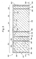
- FIG. 3 is a cross-sectional view of half of a filter cartridge 300 according to an embodiment of the present invention, wherein the end connectors are removed.
- the other half of the cartridge cross-section (not shown) is a mirror image of the cartridge half cross-section shown, along centerline 302 of FIG. 3 .
- the cartridge 300 includes a tubular housing 304 having an inner wall 306 and an outer wall 308.
- the tubular housing 304 has, by way of example, five sections 310, 312, 314, 316, and 318.
- the sections 310, 312, 314, 316, and 318 have lengths having an inner diameter defined by the inner wall 306 that is constant from a first end 315 to a second end 325 of the tubular housing 304.
- Annular flow deflectors 320, 322, 324, and 326 extend radially inwardly from the inner wall 306.
- the annular flow deflectors 320, 322, 324, and 326 are integrally molded with the 20 inner wall 306 of the tubular housing 304.
- the concentric surface of the annular flow deflectors 320, 322, 324, and 326 can have a width equal to approximately 1.0 to 5.0 percent of the diameter of the inner wall 306 of the tubular housing 304.
- a first end cap or connector (not shown) is adapted to seal the first end 315 of the cartridge 300 except at an entrance port where fluid can enter the cartridge.
- a second end cap or connector (not shown) is adapted to seal the second end 325 except at an exit port where fluid can exit the cartridge. Details of the first and second connectors are shown in FIGS. 4-6 .
- Sections of various filter media are contained within the tubular housing 304.
- at least one filter medium section spans portions of at lest two lengths of inner wall sections 31, 312, 314, 316, and 318 such that the filter medium section traverses an annular flow deflector 320, 322, 324, or 326.
- Thick, porous filter pads 330, 332, and 334 can be used to contain filter media within the tubularhousing 304 or can be used to maintain separation between two adjacent filter media sections, for example, between granular filter media sections having different and widely disparate average granule diameters.
- Thinner, porous filter paper 336, 338, and 340 can be used, for example, to maintain separation between two adjacent granular filter media sections having similar average granule diameters.
- the filter pads 330, 332, and 334, and the filter papers 336, 338, and 340 are each preferably disk-shaped and each preferably has an outer periphery that matches the inner periphery of the tubular housing 304 at the location of the pad or paper within the tubular housing 304.
- the various filter media sections within the tubular housing can include any of a variety of filter media materials and combinations thereof.
- Figs. 1-3 are for example only and in no way limit the filter media used or the order in which the filter media can be disposed with respect to the direction of flow of the fluid.
- Activated carbon can be used as a filter medium to bind heavy metals, oxidants, and chloramines.
- An immobilized enzyme such as urease can be used in a filter medium to convert urea to ammonium carbonate by enzymatic conversion.
- Urease can be immobilized by adsorption, covalent bonding, intermolecular cross-linking, entrapment within cross-linked polymers, microencapsulation, and containment within a semipermeable membrane device.
- Alumina (Al 2 O 3 ), activated carbon, anion exchange resins, and diatomaceous earth can be used as adsorbents.
- Urease can be used to covalently bond water-insoluble polymers to form enzyme-polymer conjugates via activation procedures or reactive polymers.
- Multifunctional reagents for example, glutaraldehyde and hexamethylene diamine can be used to affect intermolecular cross-linking of urease.
- Urease can be entrapped within a cross-linked polymer, such as, for example, polyacrylamide gel.
- Urease can be microencapsulated using, for example, nylon, cellulose nitrate, ethyl cellulose, or polyamide.
- Urease can be contained within some permeable membrane device, such as, for example, AMICOM ultra-filtration cells, available from Fisher Scientific, Pittsburgh, PA, or DOW hollow fiber beaker device, from The Dow ChemicalCo., Midland, MI.
- the use of activated carbon to remove chlorine, if used, should precede the immobilized enzyme medium because chlorine can deactivate the enzyme.
- Cation exchange materials can be used to bind ammonium, calcium, magnesium, potassium, and other cations as well as toxic trace metals in tap water. Another function of these filter media can be to convert carbonate from urea hydrolysis to bicarbonate.
- Such cation exchange materials can include zirconium phosphate, titanium phosphate, or zeolite.
- Anion exchange filter media bind phosphate, fluoride, and other heavy metals.
- Bi-products of the anion exchange filter media can include acetate and bicarbonate, which also corrects for metabolic acidosis of a patient's blood.
- Such filter media can include hydrous zirconium oxide of the acetate form, hydrous silica, stannic oxide, titanium oxide, antimonic acid, hydrous tungsten oxide, or sodium zirconium carbonate.
- a filter medium adapted to remove chlorine from tap water is preferred unless highly purified water is used as a base for the dialysate.
- the medium can be activated carbon.
- the cation exchange filter medium for example, zirconium phosphate, as shown in Figs. 1-3 , includes a section wherein flow deflectors 122, 124, and 126 ( Fig. 1 ), 222, 224, and 226 ( Fig. 2 ), and 322, 324, and 326 ( Fig. 3 ), are provided between the first end of the cation exchange filter medium section and the second end of the cation exchange filter medium section.
- at least one annular flow deflector is provided at about the midway point of the cation exchange filter medium section.
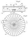
- Fig. 4 is a cross-sectional view of a second connector 400 adapted to seal the second end of the tubular housing (not shown).
- the connector 400 has an inner side 402, an outer side 403, an exit port 404, and radially extending ribs or guide vanes 406 and 408, such that the inner side 402 intersects the inner wall of the tubular housing (not shown) when sealed on the housing.
- the radially extending ribs 406 extend from an outer periphery of the inner side 402 inward toward the exit port 404 and approach, but do not contact the exit port 404.
- the radially extending ribs 408 extend from an outer periphery of the inner side 402 inward toward the exit port 404 and terminate immediately adjacent the exit port 404.
- the fluid is directed radially inward to the exit port 404 by the radially extending ribs 406 and 408.
- Fig. 5 is a cross-sectional view of a first connector 450 of Fig. 6 cut through line I-I and adapted to seal the first end of the tubular housing (not shown).
- the connector 450 has an inner side 452, an outer side 453, an entrance port 454, and radially extending ribs or guide vanes 456 and 458, such that the inner side 452 intersects the inner wall of the tubular housing (not shown) when sealed on the housing.
- the radially extending ribs 456 extend from an outer periphery of the inner side 452 inward toward the entrance port 454 and approach, but do not contact the entrance port 454.
- the radially extending ribs 458 extend from an outer periphery of the inner side 452 inward toward the entrance port 454 and terminate immediately adjacent the entrance port 454. As the flow of a fluid enters the first end of the tubular housing (not shown) through the entrance port 454, the fluid is directed radially outward from the entrance port 454 by the radially extending ribs 456 and 458.
- Fig. 6 is a top view of the first connector 450 and illustrates an exemplary embodiment of the radially extending ribs 456 and 458, the entrance port 454, and the inner side 452.
- Fig. 7 is a diagram of a cross section of the filter medium 500 in a conventional filter cartridge apparatus following filtration of a fixed volume of fluid.
- the cross section is representative of filter medium taken from a tubular housing wherein the diameter of the inner wall of the tubular housing remains constant in a direction from a first end (bottom end) of the tubular housing to a second end (top end) of the tubular housing.
- the cross-section is also representative of a filter medium taken from a section of a tubular housing wherein the section has a continuous average inner diameter.
- the gray area 502 shown in Fig. 7 illustrates the flow of fluid through a zirconium phosphate filter medium.
- the white area 504 illustrates the area of zirconium phosphate filter medium through which the fluid has not flowed. Wicking is evident at the intersection of the white and gray areas in regions adjacent the inner wall of the tubular housing. Experimental results show that approximately 50 percent of the filter medium in such a design may not be utilized.
- Fig. 8 is a diagram of a cross-section of zirconium phosphate filter medium 510 following filtration of a fixed volume of fluid through a filter cartridge assembly.
- the cross-section is representative of a tubular housing having four sections. The sections have progressively smaller average inner diameters in a direction from a first end (bottom end) to a second end (top end) of the tubular housing.
- the inner wall of the tubular housing from which the medium was removed was provided with shoulders defining intersections between the respective sections. The shoulders acted as flow deflectors.
- the gray area 512 shown in Fig. 8 illustrates the flow of fluid through zirconium phosphate filter medium.
- the white area 514 illustrates an area of zirconium phosphate filter medium that has not been utilized to filter the fluid.
- Experimental results show that the filter medium had a much higher utilization rate than the filter medium from the filter cartridge shown in Fig. 7 ,98 percent versus 50 percent, respectively. The experimental results indicate that laminar flow of fluid was substantially maintained throughout the filter medium and wicking did not occur.
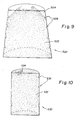
- Fig. 9 is a diagram of a cross-section of zirconium phosphate filter medium 520 following filtration of a fixed volume of fluid in a filter cartridge apparatus of the present invention.
- the cross-section is representative of filter medium removed from a tubular housing having a continuously decreasing inner diameter from a first end (bottom end) of the tubular housing to a second end (top end) of the tubular housing.
- the indentations 526 approximately perpendicular to the inner wall of the tubular housing result from a molding of the filter medium around the annular flow deflectors on the inner wall of the tubular housing.
- the gray area 522 shown in Fig. 9 illustrates the flow of fluid through the zirconium phosphate filter medium.
- the white area 524 illustrates an area of zirconium phosphate filter medium that has not been utilized to filter the fluid.
- Experimental results show that the filter medium has a much higher utilization rate than the filter medium used in the filter cartridge shown in FIG. 7 , 95 percent versus 50 percent, respectively. The experimental results indicate that laminar flow of the fluid was substantially maintained throughout the filter medium and wicking did not occur.
- FIG. 10 is a diagram of a cross-section of zirconium phosphate filter medium 530 removed from a filter cartridge assembly following filtration of a fixed volume of fluid.
- the cross-section is representative of a tubular housing wherein the tubular housing has a constant inner diameter from a first end (bottom end) of the tubular housing to a second end (top end) of the tubular housing.
- the indentations 536 perpendicular to the inner wall of the tubular housing result from a molding of the filter medium around the annular flow deflectors on the inner wall of the tubular housing.
- the gray area 532 shown in FIG. 10 illustrates the flow of fluid through zirconium phosphate filter medium.
- the white area 534 illustrates an area of zirconium phosphate filter medium that has not been utilized to filter the fluid.
- Experimental results show that the filter medium has a much higher utilization rate than the filter medium from the filter cartridge shown in FIG. 7 , 99.5 percent versus 50 percent, respectively. The experimental results indicate that laminar flow of the fluid was substantially maintained throughout the filter medium and wicking did not occur.
- a fluid is filtered using an assembly of the present invention.
- a fluid enters the filter cartridge apparatus through an end connector entrance port and is immediately directed radially outwardly by a plurality of radially extending ribs on the inner surface of the connector.
- the fluid then begins to flow through the filter media within the tubular housing of the assembly.
- the fluid hydrates the filter media during use.
- Some filter media may expand to up to 105% of its dry volume.
- the tubular housing preferably flexes to accommodate the increased volume of the filter media. Uniform, compact, and level packing of each section of the filter media is required to ensure laminar flow of the fluid within the tubular housing.
- the inner walls of the tubular housing can include a semi-rigid, thin-walled material, for example, polypropylene or another plastic of similar physical characteristics.
- the thickness of the wall of the tubular housing is preferably sufficient to ensure structural rigidity and protection during manufacturing, shipping, installation, and use, yet preferably is thin enough to be flexible to accommodate the expansion of the filter media within the tubular housing.
Landscapes
- Health & Medical Sciences (AREA)
- Urology & Nephrology (AREA)
- Heart & Thoracic Surgery (AREA)
- Anesthesiology (AREA)
- Hematology (AREA)
- Chemical Kinetics & Catalysis (AREA)
- Vascular Medicine (AREA)
- Engineering & Computer Science (AREA)
- Chemical & Material Sciences (AREA)
- Biomedical Technology (AREA)
- Emergency Medicine (AREA)
- Life Sciences & Earth Sciences (AREA)
- Animal Behavior & Ethology (AREA)
- General Health & Medical Sciences (AREA)
- Public Health (AREA)
- Veterinary Medicine (AREA)
- External Artificial Organs (AREA)
- Separation Using Semi-Permeable Membranes (AREA)
- Water Treatment By Sorption (AREA)
Abstract
Description
- The present invention relates to filter cartridges and methods for filtering fluids.
- Filter cartridges are used in many applications, including medical devices. In the medical field, filter cartridges containing certain powdered filter media are used. One application for such a filter cartridge is in a dialysis system.
- The
United States patent US 2,328,381 discloses a pipe joint. A compact biofilter for drinking water treatment is disclosed in theUnited States patent US 5,032,261 . A plastic media filter is disclosed in theUnited States patent US 5,350,505 . theUnited States patent US 3,357,563 discloses an apparatus for treating water. A cartridge useful for cleaning dialysis solutions is disclosed in United States patent applicationUS 2002/0112609 , which was published after the priority date of the current application. The patent specifications ofUK 1,470,206 United States patent US 3,669,880 . - The closest prior art is acknowledged in
US 2,328,381 . - Systems for patients requiring hemodialysis or peritoneal dialysis can involve pumping a large volume of dialysate through a dialyzing device. In these devices, the used dialysate is generally discarded after a single passing.
- More recent embodiments of dialysis devices involve pumping a fixed volume of dialysate through a dialyzing device, whereupon the used dialysate flows through a filter cartridge and is then returned to a dialysate reservoir for reuse. Flow through the cartridge, however, does not optimize filtering of the dialysate through various granular filtering media.
- Fluid flows through filter media of varying particle sizes and granular diameters at various rates and pressures. Fluid flows at a higher rate and at a lower pressure through granules of larger diameter. Conversely, fluid flows at a slower rate and at a higher pressure through granules of smaller diameter. The flow of a fluid through a filter cartridge having filter media sections of varying granule diameters takes different directional flow paths through the respective sections. As a result, fluid flow through a powdered medium containing large diameter granules disposed in a filter cartridge is laminar. Fluid flow through a powdered filter medium containing small diameter granules disposed in a filter cartridge is not laminar and results in a condition known as wicking. Wicking occurs when the fluid generally flows in the direction of areas of least pressure, which tend to be areas between the inner wall of the tubular housing and the powdered filter medium. Wicking results in the fluid bypassing the majority of the surface area of the granular filter medium. As a result, filtering is inefficient.
- A need therefore exists for a filter cartridge assembly that optimizes filtering efficiency of a fluid.
- The object of the invention is solved by the subject matter of the independent claims.
- According to an embodiment of the present invention, a filter cartridge assembly of generally cylindrical shape is provided that includes a tubular housing having an inner wall, a first end, a second end, and a plurality of annular flow deflectors that extend radially inwardly from the inner wall of the tubular housing to focus the flow of fluid through the center of the filter media in the cartridge. The inner wall is of constant diameter. A first connector is adapted to seal the first end except at an entrance port where fluid can enter the filter cartridge. A second connector is adapted to seal the second end except at the exit port where fluid can exit the filter cartridge.
- Powdered filter media for performing many different filtering functions can be used. The different media can cause different reactions, including enzymatic decomposition, cation exchange, anion exchange, or chemical adsorption. The various filter media can consist of different sized and shaped granular or powdered insoluble chemicals that have different physical and chemical characteristics.
- According to methods of the present invention, a filter cartridge assembly is provided according to any one of the embodiments listed herein, and a fluid is flowed through or circulated through the filter cartridge by a fluid circulating device, a pump, gravity, or a gravity column.
-
-
FIG. 1 is a cross-sectional view of half of a filter cartridge not part of the present invention, but important for its understanding, wherein the tubular housing has five sections, each successive section has a smaller average inner diameter than the preceding section, and the inner wall of the tubular housing has stepped portions or shoulders at the intersection between each section of the housing; -
FIG. 2 is a cross-sectional view of half of a filter cartridge not part of the invention, but important for its understanding, wherein the diameter of the inner wall of the tubular housing continuously tapers from the direction of a first end to a second end of the housing; -
FIG. 3 is a cross-sectional view of half of another filter cartridge according to an embodiment of the present invention wherein annular flow deflectors are positioned on the inner wall of a cylindrical tubular housing; -
FIG. 4 is a cross-sectional side view of an end cap or connector useful with the filter cartridges; -
FIG. 5 is a cross-sectional side view of an end cap or connector useful with the filter cartridge; -
FIG. 6 is an end view of the inner surface of the connector shown inFIG. 5 ; -
FIG. 7 is an illustration of a cross-section of the filter medium following filtration of a fixed volume of fluid in a conventional filter cartridge apparatus; -
FIG. 8 is an illustration of a cross-section of a zirconium phosphate filter medium following filtration of a fixed volume of fluid in a filter cartridge assembly; -
FIG. 9 is an illustration of a cross-section of a zirconium phosphate filter medium following filtration of a fixed volume of fluid in a filter cartridge assembly; -
FIG. 10 is an illustration of a cross-section of a zirconium phosphate filter medium following filtration of a fixed volume of fluid in a filter cartridge assembly. - The present invention overcomes the problems of the prior art by providing a filter cartridge assembly of simple construction and that efficiently filters fluids. The filter cartridge assembly of the present invention can advantageously be less costly to manufacture than conventional filter cartridges and can be employed in recirculating systems. The filter cartridge assembly of the present invention is also less costly to use than conventional filter cartridges because it is more efficient at filtering fluid per unit volume of filter media.
- The present invention is also directed to filter cartridge assemblies including various powdered filtered media contained therein. The various powdered filter media can include those media described in
U.S. Patent Application No. 09/996,505 to Wong , filed concurrently with the present application and entitled "Cartridges Useful in Cleaning Dialysis Solutions" and published asUS2002/0112609 A1 . - A filter cartridge assembly is provided that includes a tubular housing having an inner wall, a first end, a second end, and at least three sections having progressively smaller average inner diameters in a direction from the first end to the second end. A first connector is adapted to seal the first end except at an entrance port where fluid can enter the cartridge. A second connector is adapted to seal the second end except at an exit port where fluid can exit the cartridge. The inner wall of the tubular housing is provided with shoulders at the intersections of the respective sections. The shoulders deflect the flow of fluid from the outer periphery of the filter media to paths that flow through the center of the filter media.
- Another filter cartridge assembly of conical shape is provided that includes a tubular housing having an inner wall, a first end, a second end, and a plurality of annular flow deflectors that extend radially inwardly from the inner wall of the tubular housing. By conical what is meant is generally conical, preferably perfectly conical, and more preferably having a continuously decreasing inner diameter defined by the inner wall regardless of the shape of the outside of the filter cartridge. The annular flow deflectors can be integrally formed or molded with the inner wall of the tubular housing or attached, mounted, fixed, or positioned on the inner wall of the tubular housing by a compression fit, threaded engagement, by snapping in a groove, or by other means. For example, adhesive well known to those of ordinary skill in the art can be used to affix the annular flow deflectors to the inner wall. For another example, the annular flow deflector can be held in place by filter media in a tightly packed, compressed, or settled form. A first connector is adapted to seal the first end except at an entrance port where fluid can enter the filter cartridge. A second connector is adapted to seal the second end except at an exit port where fluid can exit the filter cartridge. The inner wall of the tubular housing is continuously tapering in a direction from the first end to the second end.
- According to an embodiment of the present invention, a filter cartridge assembly having a cylindrical shape is provided that includes a tubular housing having an inner wall, a first end, a second end, and a plurality of annular flow deflectors that extend radially inwardly from the inner wall. By cylindrical, what is meant is generally cylindrical, preferably perfectly cylindrical, more preferably having a constant inner diameter defined by the inner wall regardless of the shape of the outside of the filter cartridge. The annular flow deflectors can be integrally formed or molded with the inner wall of the tubular housing or attached, mounted, fixed, or positioned on the inner wall of the tubular housing by a compression fit, threaded engagement, by snapping in a groove or by other means. For example, adhesive well known to those of ordinary skill in the art can be used to affix the annular flow deflectors to the inner wall. For another example, the annular flow deflector can be held in place by filter media in a tightly packed, compressed, or settled form. A first connector is adapted to seal the first end except at an entrance port where fluid can enter the filter cartridge. A second connector is adapted to seal the second end except at an exit port where fluid can exit the filter cartridge.
- According to methods, any of the filter cartridge assemblies of the present invention can be used in a recirculating system to filter a recirculating fluid.
- The diameter of the inner wall of the tubular housing can be modulated to regulate pressure and the flow rate. The diameter of the inner wall, for example, from about 4 to about 7 inches, can result in a flow rate of, for example, from about 150 ml/min to about 500 ml/min at a pressure of less than or equal to, for example, about 172,4 kPa (pounds per square inch).
- Some filter media, for example, activated carbon, have relatively large granules (coarse media), for example, with diameters of from about 425 micrometers to about 1,700 micrometers. Some filter media, for example, zirconium phosphate or alumina, have relatively small granules (fine media), for example, having diameters of from about 20 micrometers to about 100 micrometers, e.g. from about 45 micrometers to about 100 micrometers.
- It is a feature of this invention that laminar flow of fluid through the tubular housing of the filter cartridge apparatus is maintained. Annular flow deflectors are used to ensure laminar flow of the fluid through fine filter media. Pumping the fluid against the force of gravity, for example, by standing the assembly on end, is further used to maintain laminar flow of the fluid through the tubular housing.
- Experiments show that the flow of fluid through a conventional filter cartridge containing a fine medium can result in wicking and non-laminar flow. Wicking occurs when the flow of fluid is generally directed toward the inner wall to an area of least resistance and pressure between the inner wall and the filter medium. Therefore, the fluid does not contact a substantial portion of the surface area of the total filter medium, resulting in low utilization of the filter medium. In the filter cartridge of the present invention, the annular flow deflectors deflect the flow of fluid through filter medium, particularly through fine medium. The fluid contacts substantially all of the surface area of the fine filter medium, resulting in high utilization of the filter medium.
- It is a feature of this invention that only a low percentage of the fluid bypasses a section of the filter media, for example, less than 20 percent bypasses the filter media of each, more preferably less than 10 percent, and even more preferably less than3 percent bypasses the filter media of each section. Preferably, the annular flow deflectors are attached to the inner wall of the tubular housing within a section of a filter medium.
- The extent that the annular flow deflector extends into the housing from the inner wall is preferably from about 1.0 percent to 5.0 percent of the diameter of the inner wall at the flow deflector. If the width of the concentric surface of the annular flow deflector is too great, utilization of the filter medium behind the annular flow deflector is lower than the average utilization of the filter medium. If the width of the concentric surface of the annular flow deflector is too little, deflection of the fluid may not result in laminar flow and wicking occurs.
- An embodiment of the present invention includes a first connector and a second connector adapted to seal the first end and the second end, respectively. The first connector and the second connector can be hermetically sealed to the first end and the second end using, for example, a variety of conventional sealing techniques, such as, but not limited to, EMABOND, Ashland Specialty Chemical Company, a division of Ashland, Inc., Columbus, Ohio, or another sealing composition or method such as ultrasound, heat, chemical bonding, vibration, physical latch, or gasket. The sealing method preferably is capable of withstanding moderate pressures of greater than 275,8 kPa (40 pounds per square inch).
- In another embodiment of the present invention, the entrance port and exit port of the filter cartridge assembly are connected to a fluid recirculating or pumping system. The fluid recirculating system can be, for example, a dialysis machine, including a portable dialysis machine. The fluid recirculating system can include, for example, a fluid pump, a dialyzing device, and a fluid reservoir.
- According to an embodiment of the present invention, methods of preparing an assembly according to the present invention are provided wherein a filter medium seal is inserted into one of the first end and the second end of the tubular housing. The filter medium seal or part thereof can be a filter paper, a filter pad, a first connector, and a second connector. Many seals can be used. Each filter medium seal is preferably disk-shaped and preferably has an outer periphery that matches the inner periphery of the tubular housing at the location of the seal within the tubular body. After the seal is inserted, a filter medium is introduced into the tubular housing to form a part of or an entire filter medium section, and the filter medium is subsequently settled as by vibrating, packing, shaking, jogging, compressing, or otherwise increasing the density of the filter medium section. Following settling and optional additional placement of at least one seal in the tubular body, the other of the first and second ends of the tubular housing is sealed with another filter medium seal to contain the filter medium section and maintain the density of the filter medium section.
- Referring now to the figures,
Fig.1 is a cross-sectional view of half of afilter cartridge assembly 100 wherein the end connectors are removed. The other half of the cartridge cross-section (not shown) is a mirror image of the cartridge half cross-section shown, alongcenterline 102 ofFig.1 . Thecartridge 100 includes atubular housing 104 having aninner wall 106 and anouter wall 108. Thetubular housing 104 has, by way of example, fivesections first end 115 to asecond end 125 of thetubular housing 104. Theinner wall 106 of thetubular housing 104 is provided withshoulders inner wall 106. A first end cap or connector (not shown) is adapted to seal thefirst end 115 of thecartridge 100 except at an entrance port where fluid can enter the cartridge. A second end cap or connector (not shown) is adapted to seal thesecond end 125 except at an exit port where fluid can exit the cartridge. Details of the first and second connectors are shown inFigs. 4-6 . - Sections of various filter media are contained within the
tubular housing 104. Preferably, at least one filter medium section spans portions of at least two lengths of inner wall sections110, 112, 114, 116, and 118 such that the filter medium section traverses ashoulder porous filter pads tubular housing 104 or can be used to maintain separation between two adjacent filter media sections, for example, between granular filter media sections having different and widely disparate average granule diameters. Thinner,porous filter paper filter pads filter papers tubular housing 104 at the location of the respective pad or paper within thetubular housing 104. - For example purposes only, the various filter media sections within the
tubular housing 104 can include, as shown, a granular activatedcarbon section 142, an immobilizedenzyme section 144, a powdered alumina (Al2O3)section 146, azirconium phosphate section 148, and asection 150 that includes a mixture of hydrous zirconium oxide of the acetate form and sodium zirconium carbonate. -
Fig. 2 is a cross-sectional view of half of afilter cartridge 200 wherein the end connectors are removed. The other half of the cartridge cross-section (not shown) is a mirror image of the cartridge half cross-section shown, alongcenterline 202 ofFig. 2 . Thecartridge 200 includes atubular housing 204 having aninner wall 206 and anouter wall 208. Thetubular housing 204 has, by way of example, fivesections sections inner wall 206, that continuously tapers in a direction from afirst end 215 to asecond end 225 of thetubular housing 204. -
Annular flow deflectors inner wall 206. Theannular flow deflectors tubular housing 204 and held in place adjacent to theinner wall 206 by the compression of the powdered filter media sections. After filter media is inserted and packed into thetubular housing 204, theannular flow deflectors annular flow deflectors inner wall 206 of thetubular housing 204. A first end cap or connector (not shown) is adapted to seal thefirst end 215 of thecartridge 200 except at an entrance port where fluid can enter the cartridge. A second end cap or connector (not shown) is adapted to seal thesecond end 225 except at an exit port where fluid can exit the cartridge. Details of the first and second connectors are shown inFigs. 4-6 . - Sections of various filter media are contained within the
tubular housing 204. Preferably, at least one filter medium section spans portions of at least two lengths of inner wall sections210, 212, 214,216, and 218 such that the filter medium section traverses anannular flow deflector porous filter pads tubular housing 204 or can be used to maintain separation between two adjacent filter media sections, for example, between granular filter media sections having different and widely disparate average granule diameters. A thick filter pad can be used at the respective intersection of each two adjacent sections of filter media. Thinner,porous filter paper filter pads filter papers tubular housing 204 at the location of the pad or paper within thetubular housing 204. - The various filter media sections within the
tubular housing 204 can include, as shown, a granular activatedcarbon section 242, an immobilizedenzyme section 244, a powdered alumina (Al2O3)section 246, azirconium phosphate section 248, and asection 250 that includes a mixture of hydrous zirconium oxide of the acetate form and sodium zirconium carbonate. -
FIG. 3 is a cross-sectional view of half of afilter cartridge 300 according to an embodiment of the present invention, wherein the end connectors are removed. The other half of the cartridge cross-section (not shown) is a mirror image of the cartridge half cross-section shown, alongcenterline 302 ofFIG. 3 . Thecartridge 300 includes atubular housing 304 having aninner wall 306 and anouter wall 308. Thetubular housing 304 has, by way of example, fivesections sections inner wall 306 that is constant from afirst end 315 to asecond end 325 of thetubular housing 304. -
Annular flow deflectors inner wall 306. Theannular flow deflectors inner wall 306 of thetubular housing 304. The concentric surface of theannular flow deflectors inner wall 306 of thetubular housing 304. A first end cap or connector (not shown) is adapted to seal thefirst end 315 of thecartridge 300 except at an entrance port where fluid can enter the cartridge. A second end cap or connector (not shown) is adapted to seal thesecond end 325 except at an exit port where fluid can exit the cartridge. Details of the first and second connectors are shown inFIGS. 4-6 . - Sections of various filter media are contained within the
tubular housing 304. Preferably, at least one filter medium section spans portions of at lest two lengths ofinner wall sections annular flow deflector porous filter pads tubularhousing 304 or can be used to maintain separation between two adjacent filter media sections, for example, between granular filter media sections having different and widely disparate average granule diameters. Thinner,porous filter paper filter pads filter papers tubular housing 304 at the location of the pad or paper within thetubular housing 304. - The various filter media sections within the tubular housing can include any of a variety of filter media materials and combinations thereof. By way of example, the figures depict filter media sections that can include, as shown, a granular activated
carbon section 342, an immobilizedenzyme section 344, a powdered alumina (Al2O3)section 346, azirconium phosphate section 348, and asection 350 that includes a mixture of hydrous zirconium oxide of the acetate form and sodium zirconium carbonate. - The various filter media shown in
Figs. 1-3 are for example only and in no way limit the filter media used or the order in which the filter media can be disposed with respect to the direction of flow of the fluid. - Activated carbon can be used as a filter medium to bind heavy metals, oxidants, and chloramines. An immobilized enzyme such as urease can be used in a filter medium to convert urea to ammonium carbonate by enzymatic conversion. Urease can be immobilized by adsorption, covalent bonding, intermolecular cross-linking, entrapment within cross-linked polymers, microencapsulation, and containment within a semipermeable membrane device. Alumina (Al2O3), activated carbon, anion exchange resins, and diatomaceous earth can be used as adsorbents. Urease can be used to covalently bond water-insoluble polymers to form enzyme-polymer conjugates via activation procedures or reactive polymers. Multifunctional reagents, for example, glutaraldehyde and hexamethylene diamine can be used to affect intermolecular cross-linking of urease. Urease can be entrapped within a cross-linked polymer, such as, for example, polyacrylamide gel. Urease can be microencapsulated using, for example, nylon, cellulose nitrate, ethyl cellulose, or polyamide. Urease can be contained within some permeable membrane device, such as, for example, AMICOM ultra-filtration cells, available from Fisher Scientific, Pittsburgh, PA, or DOW hollow fiber beaker device, from The Dow ChemicalCo., Midland, MI. The use of activated carbon to remove chlorine, if used, should precede the immobilized enzyme medium because chlorine can deactivate the enzyme.
- Cation exchange materials can be used to bind ammonium, calcium, magnesium, potassium, and other cations as well as toxic trace metals in tap water. Another function of these filter media can be to convert carbonate from urea hydrolysis to bicarbonate. Such cation exchange materials can include zirconium phosphate, titanium phosphate, or zeolite.
- Anion exchange filter media bind phosphate, fluoride, and other heavy metals. Bi-products of the anion exchange filter media can include acetate and bicarbonate, which also corrects for metabolic acidosis of a patient's blood. Such filter media can include hydrous zirconium oxide of the acetate form, hydrous silica, stannic oxide, titanium oxide, antimonic acid, hydrous tungsten oxide, or sodium zirconium carbonate.
- For hemodialysis, a filter medium adapted to remove chlorine from tap water is preferred unless highly purified water is used as a base for the dialysate. The medium can be activated carbon.
- The cation exchange filter medium, for example, zirconium phosphate, as shown in
Figs. 1-3 , includes a section whereinflow deflectors Fig. 1 ), 222, 224, and 226 (Fig. 2 ), and 322, 324, and 326 (Fig. 3 ), are provided between the first end of the cation exchange filter medium section and the second end of the cation exchange filter medium section. Preferably, at least one annular flow deflector is provided at about the midway point of the cation exchange filter medium section. -
Fig. 4 is a cross-sectional view of asecond connector 400 adapted to seal the second end of the tubular housing (not shown). Theconnector 400 has aninner side 402, anouter side 403, anexit port 404, and radially extending ribs or guidevanes inner side 402 intersects the inner wall of the tubular housing (not shown) when sealed on the housing. Theradially extending ribs 406 extend from an outer periphery of theinner side 402 inward toward theexit port 404 and approach, but do not contact theexit port 404. Theradially extending ribs 408 extend from an outer periphery of theinner side 402 inward toward theexit port 404 and terminate immediately adjacent theexit port 404. As the flow of a fluid reaches the second end of the tubular housing (not shown) from the direction of the first end of the tubular housing (not shown), the fluid is directed radially inward to theexit port 404 by theradially extending ribs -
Fig. 5 is a cross-sectional view of afirst connector 450 ofFig. 6 cut through line I-I and adapted to seal the first end of the tubular housing (not shown). Theconnector 450 has aninner side 452, anouter side 453, anentrance port 454, and radially extending ribs or guidevanes inner side 452 intersects the inner wall of the tubular housing (not shown) when sealed on the housing. Theradially extending ribs 456 extend from an outer periphery of theinner side 452 inward toward theentrance port 454 and approach, but do not contact theentrance port 454. Theradially extending ribs 458 extend from an outer periphery of theinner side 452 inward toward theentrance port 454 and terminate immediately adjacent theentrance port 454. As the flow of a fluid enters the first end of the tubular housing (not shown) through theentrance port 454, the fluid is directed radially outward from theentrance port 454 by theradially extending ribs -
Fig. 6 is a top view of thefirst connector 450 and illustrates an exemplary embodiment of theradially extending ribs entrance port 454, and theinner side 452. -
Fig. 7 is a diagram of a cross section of thefilter medium 500 in a conventional filter cartridge apparatus following filtration of a fixed volume of fluid. The cross section is representative of filter medium taken from a tubular housing wherein the diameter of the inner wall of the tubular housing remains constant in a direction from a first end (bottom end) of the tubular housing to a second end (top end) of the tubular housing. The cross-section is also representative of a filter medium taken from a section of a tubular housing wherein the section has a continuous average inner diameter. - The
gray area 502 shown inFig. 7 illustrates the flow of fluid through a zirconium phosphate filter medium. Thewhite area 504 illustrates the area of zirconium phosphate filter medium through which the fluid has not flowed. Wicking is evident at the intersection of the white and gray areas in regions adjacent the inner wall of the tubular housing. Experimental results show that approximately 50 percent of the filter medium in such a design may not be utilized. -
Fig. 8 is a diagram of a cross-section of zirconiumphosphate filter medium 510 following filtration of a fixed volume of fluid through a filter cartridge assembly. The cross-section is representative of a tubular housing having four sections. The sections have progressively smaller average inner diameters in a direction from a first end (bottom end) to a second end (top end) of the tubular housing. The inner wall of the tubular housing from which the medium was removed was provided with shoulders defining intersections between the respective sections. The shoulders acted as flow deflectors. - The
gray area 512 shown inFig. 8 illustrates the flow of fluid through zirconium phosphate filter medium. Thewhite area 514 illustrates an area of zirconium phosphate filter medium that has not been utilized to filter the fluid. Experimental results show that the filter medium had a much higher utilization rate than the filter medium from the filter cartridge shown inFig. 7 ,98 percent versus 50 percent, respectively. The experimental results indicate that laminar flow of fluid was substantially maintained throughout the filter medium and wicking did not occur. -
Fig. 9 is a diagram of a cross-section of zirconiumphosphate filter medium 520 following filtration of a fixed volume of fluid in a filter cartridge apparatus of the present invention. The cross-section is representative of filter medium removed from a tubular housing having a continuously decreasing inner diameter from a first end (bottom end) of the tubular housing to a second end (top end) of the tubular housing. Theindentations 526 approximately perpendicular to the inner wall of the tubular housing result from a molding of the filter medium around the annular flow deflectors on the inner wall of the tubular housing. - The
gray area 522 shown inFig. 9 illustrates the flow of fluid through the zirconium phosphate filter medium. Thewhite area 524 illustrates an area of zirconium phosphate filter medium that has not been utilized to filter the fluid. Experimental results show that the filter medium has a much higher utilization rate than the filter medium used in the filter cartridge shown inFIG. 7 , 95 percent versus 50 percent, respectively. The experimental results indicate that laminar flow of the fluid was substantially maintained throughout the filter medium and wicking did not occur. -
FIG. 10 is a diagram of a cross-section of zirconiumphosphate filter medium 530 removed from a filter cartridge assembly following filtration of a fixed volume of fluid. The cross-section is representative of a tubular housing wherein the tubular housing has a constant inner diameter from a first end (bottom end) of the tubular housing to a second end (top end) of the tubular housing. Theindentations 536 perpendicular to the inner wall of the tubular housing result from a molding of the filter medium around the annular flow deflectors on the inner wall of the tubular housing. - The
gray area 532 shown inFIG. 10 illustrates the flow of fluid through zirconium phosphate filter medium. Thewhite area 534 illustrates an area of zirconium phosphate filter medium that has not been utilized to filter the fluid. Experimental results show that the filter medium has a much higher utilization rate than the filter medium from the filter cartridge shown inFIG. 7 , 99.5 percent versus 50 percent, respectively. The experimental results indicate that laminar flow of the fluid was substantially maintained throughout the filter medium and wicking did not occur. - According to methods of the present invention, a fluid is filtered using an assembly of the present invention. In such methods, a fluid enters the filter cartridge apparatus through an end connector entrance port and is immediately directed radially outwardly by a plurality of radially extending ribs on the inner surface of the connector. The fluid then begins to flow through the filter media within the tubular housing of the assembly. The fluid hydrates the filter media during use. Some filter media may expand to up to 105% of its dry volume. As this occurs, the tubular housing preferably flexes to accommodate the increased volume of the filter media. Uniform, compact, and level packing of each section of the filter media is required to ensure laminar flow of the fluid within the tubular housing.
- The inner walls of the tubular housing can include a semi-rigid, thin-walled material, for example, polypropylene or another plastic of similar physical characteristics. The thickness of the wall of the tubular housing is preferably sufficient to ensure structural rigidity and protection during manufacturing, shipping, installation, and use, yet preferably is thin enough to be flexible to accommodate the expansion of the filter media within the tubular housing.
- As fluid flows through the assembly and approaches the second end of the tubular housing, the fluid is radially directed inwardly toward the exit port on an end connector by the radially extending ribs on the inner surface of the second connector. It will be apparent to those skilled in the art that various modifications and variations can be made to the embodiments of the present invention without departing from the scope of the present invention. Thus, it is intended that the present invention cover other modifications and variations of this invention within the scope of the appended claims and their equivalents.
-
- 1. A first special filter cartridge assembly comprising: a tubular housing having an inner wall, an outer wall, a first end, and a second end, said inner wall including at least a first section, a second section, and a third section, said first section having a first length in a direction from said first end to said second end and a first average inner diameter, said second section having a second length in a direction from said first end to said second end and a second average inner diameter that is smaller than said first average inner diameter, said third section having a third length in a direction from said first end to said second end and a third average inner diameter that is smaller than said second average inner diameter, wherein the inner wall of said tubular housing includes a first shoulder at the intersection of said first section and said second section and a second shoulder at the intersection of said second section and said third section; and a plurality of filter media sections, including a first filter media section, within the tubular housing and radially contained by said inner wall, each of said plurality of filter media sections having a different filter media composition, wherein said first filter media section has a length in a direction from said first end to said second end that includes at least portions of at least two of said lengths of the inner wall sections such that said first media section traverses at least one of said shoulders.
- 2. The assembly of the first special filter cartridge assembly, wherein said assembly further comprises: a first connector that seals the first end of said tubular housing except at a centrally-located entrance port in said connector where fluid is capable of entering the assembly; and a second connector that seals the second end of said tubular body except at a centrally- located exit port where fluid is capable of exiting the cartridge.
- 3. The assembly of the first special filter cartridge assembly, wherein said assembly further contains a dialysate fluid.
- 4. The assembly of the first special filter cartridge assembly, wherein said tubular housing comprises a plastic material.
- 5. The assembly the first special filter cartridge assembly, wherein said plastic material comprises a polypropylene material.
- 6. The assembly of the first special filter cartridge assembly, wherein the thickness of said inner wall is less than, or equal to, about 3,175 mm (0.125 inch).
- 7. The assembly of the first special filter cartridge assembly, wherein said first filter media section traverses said first shoulder, said plurality of filter media sections includes a second filter media section, said second filter media section has a different filter media composition than said first filter media section, said second filter media section has a length in a direction from said first end to said second end that includes at least portions of said second length and said third length of said inner wall sections, and said second media section traverses said second shoulder.
- 8. A first special system including the assembly of the first special filter cartridge assembly, in combination with a fluid circulating device, wherein said device has an outlet and an inlet, said entrance port is in fluid communication with said outlet, and said exit port is in fluid communication with said inlet.
- 9. A first special method of filtering a fluid, comprising circulating said fluid through the above system.
- 10. A second special method of preparing the assembly of the first special filter cartridge assembly, comprising: providing said tubular housing; sealing one of said first and second end connectors to said tubular housing; introducing a first of said filter media sections into said tubular housing; settling said first media section in said tubular housing; and sealing the other of said first and second connectors to said tubular body.
- 11. A first special filter cartridge housing comprising: a tubular housing having a conical shape and including a straight inner wall, an outer wall, a first end, and a second end, said inner wall including at least a first section, a second section, and a third section, said first section having a first length in a direction from said first end to said second end and a first average inner diameter, said second section having a second length in a direction from said first end to said second end and a second average inner diameter that is smaller than said first average inner diameter, said third section having a third length in a direction from said first end to said second end and a third average inner diameter that is smaller than said second average inner diameter; and a first annular flow director extending radially inwardly from the inner wall of said tubular housing at the intersection of said first section and said second section, and a second annular flow director extending radially inwardly from the inner wall at the intersection of said second section and said third section.
- 12. A second special assembly comprising : the above filter cartridge housing; and a plurality of filter media sections, including a first filter media section, within the tubular housing and radially contained by said inner wall, each of said plurality of filter media sections having a different filter media composition, wherein said first filter media section has a length in a direction from said first end to said second end that includes at least portions of at least two of said lengths of the inner wall sections such that said first media section traverses at least one of said first and second annular flow director.
- 13. The assembly of the second special assembly, wherein said assembly further comprises: a first connector that seals the first end of said tubular housing except at a centrally-located entrance port in said connector where fluid is capable of entering the assembly; and a second connector that seals the second end of said tubular body except at a centrally- located exit port where fluid is capable of exiting the cartridge.
- 14. The assembly of the second special assembly, wherein said assembly further contains a dialysate fluid.
- 15. The filter cartridge housing of the first special filter cartridge housing, wherein said tubular housing comprises a plastic material.
- 16. The filter cartridge housing of the first special filter cartridge housing, wherein said plastic material comprises a polypropylene material.
- 17. The filter cartridge housing of the first special filter cartridge housing, wherein the thickness of said inner wall is less than, or equal to, about 3,175 mm (0.125 inch).
- 18. The filter cartridge housing of the first special filter cartridge housing, wherein said first filter media section traverses said first annular flow director, said plurality of filter media sections includes a second filter media section, said second filter media section has a different filter media composition than said first filter media section, said second filter media section has a length in a direction from said first end to said second end that includes at least portions of said second length and said third length of said inner wall sections, and said second media section traverses said second annular flow director.
- 19. A second special system including the assembly of the second special assembly, in combination with a fluid circulating device, wherein said device has an outlet and an inlet, said entrance port is in fluid communication with said outlet, and said exit port is in fluid communication with said inlet.
- 20. A third special method of filtering a fluid, comprising circulating said fluid through the system of the second special system.
- 21. A fourth special method of preparing the assembly of the second special assembly, comprising: providing said tubular housing; sealing one of said first and second end connectors to said tubular housing; introducing a first of said filter media sections into said tubular housing; settling said first media section in said tubular housing; and sealing the other of said first and second connectors to said tubular body.
- 22. A third special filter cartridge assembly comprising: a filter cartridge housing including a tubular housing having a cylindrical shape of constant inner diameter and including a straight inner wall, an outer wall, a first end, and a second end, said inner wall including at least a first section, a second section, and a third section, said first section having a first length in a direction from said first end to said second end, said second section having a second length in a direction from said first end to said second end, said third section having a third length in a direction from said first end to said second end; a first annular flow director extending radially inwardly from the inner wall of said tubular housing at the intersection of said first section and said second section, and a second annular flow director extending radially inwardly from the inner wall at the intersection of said second section and said third section; and a plurality of filter media sections, including a first filter media section, within the tubular housing and radially contained by said inner wall, each of said plurality of filter media sections having a different filter media composition, wherein said first filter media section has a length in a direction from said first end to said second end that includes at least portions of at least two of said lengths of the inner wall sections such that said first media section traverses at least one of said first and second annular flow director.
- 23. The filter cartridge assembly of the third special filter cartridge assembly, wherein said assembly further comprises: a first connector that seals the first end of said tubular housing except at a centrally-located entrance port in said connector where fluid is capable of entering the assembly; and a second connector that seals the second end of said tubular body except at a centrally located exit port where fluid is capable of exiting the cartridge.
- 24. The filter cartridge assembly of the third special filter cartridge assembly, wherein said assembly further contains a dialysate fluid.
- 25. The filter cartridge assembly of the third special filter cartridge assembly, wherein said tubular housing comprises a plastic material.
- 26. The filter cartridge assembly of the third special filter cartridge assembly, wherein said plastic material comprises a polypropylene material.
- 27. The filter cartridge assembly of the third special filter cartridge assembly, wherein the thickness of said inner wall is less than, or equal to, about 3,175 mm (0.125 inch).
- 28. The filter cartridge assembly of the third special filter cartridge assembly, wherein said first filter media section traverses said first annular flow director, said plurality of filter media sections includes a second filter media section, said second filter media section has a different filter media composition than said first filter media section, said second filter media section has a length in a direction from said first end to said second end that includes at least portions of said second length and said third length of said inner wall sections, and said second media section traverses said second annular flow director.
- 29. Another special system including the filter cartridge assembly of the third special filter cartridge assembly, in combination with a fluid circulating device, wherein said device has an outlet and an inlet, said entrance port is in fluid communication with said outlet, and said exit port is in fluid communication with said inlet.
- 30. Another special method of preparing the assembly of the third special filter cartridge assembly, comprising: providing said tubular housing; sealing one of said first and second end connectors to said tubular housing; introducing a first of said filter media sections into said tubular housing; settling said first media section in said tubular housing; and sealing the other of said first and second connectors to said tubular body.
Claims (10)
- A filter cartridge assembly (100; 200; 300) comprising:a filter cartridge housing including a tubular housing having a cylindrical shape of constant inner diameter and including a straight inner wall (106; 206; 306), an outer wall (108; 208; 308), a first end, and a second end, said inner wall including at least a first section, a second section, and a third section, said first section having a first length in a direction from said first end to said second end, said second section having a second length in a direction from said first end to said second end, said third section having a third length in a direction from said first end to said second end;a first annular flow director extending radially inwardly from the inner wall of said tubular housing at the intersection of said first section and said second section, and a second annular flow director extending radially inwardly from the inner wall at the intersection of said second section and said third section; anda plurality of filter media sections, including a first filter media section, within the tubular housing and radially contained by said inner wall, each of said plurality of filter media sections having a different filter media composition, wherein said first filter media section has a length in a direction from said first end to said second end that includes at least portions of at least two of said lengths of the inner wall sections such that said first media section traverses at least one of said first and second annular flow director.
- The assembly (100; 200; 300) of claim 1 wherein said assembly (100; 200; 300) further comprises:a first connector (450) that seals the first end of said tubular housing except at a centrally-located entrance port in said connector where fluid is capable of entering the assembly; anda second connector (400) that seals the second end of said tubular body except at a centrally-located exit port where fluid is capable of exiting the cartridge.
- The assembly (100; 200; 300) of claim 2, wherein said assembly (100; 200; 300) further contains a dialysate fluid.
- The assembly (100; 200; 300) of claim 2, wherein said tubular housing comprises a plastic material.
- The assembly (100; 200; 300) of claim 4, wherein said plastic material comprises a polypropylene material.
- The assembly (100; 200; 300) of claim 1, wherein the thickness of said inner wall is less than, or equal to, about 0.318 cm (0.125 inch).
- The assembly (100; 200; 300) of claim 1, wherein said first filter media section traverses said first annular flow director, said plurality of filter media sections includes a second filter media section, said second filter media section has a different filter media composition than said first filter media section, said second filter media section has a length in a direction from said first end to said second end that includes at least portions of said second length and said third length of said inner wall sections, and said second media section traverses said second annular flow director.
- A system including the assembly (100; 200; 300) of claim 1, in combination with a fluid circulating device, wherein said device has an outlet and an inlet, said entrance port is in fluid communication with said outlet, and said exit port is in fluid communication with said inlet.
- A method of filtering a fluid, comprising circulating said fluid through the system including the assembly (100; 200; 300) of claim 1.
- A method of preparing the assembly (100; 200; 300) of one of the claims 1 to 7, comprising:providing said tubular housing;sealing one of said first and second end connectors (450; 400) to said tubular housing;introducing a first of said filter media sections into said tubular housing;settling said first media section in said tubular housing; andsealing the other of said first and second connectors (450; 400) to said tubular body.
Applications Claiming Priority (2)
| Application Number | Priority Date | Filing Date | Title |
|---|---|---|---|
| US09/995,888 US6878283B2 (en) | 2001-11-28 | 2001-11-28 | Filter cartridge assemblies and methods for filtering fluids |
| EP02786690A EP1448250B1 (en) | 2001-11-28 | 2002-11-08 | Filter cartridge assemblies and methods of filtering fluids |
Related Parent Applications (2)
| Application Number | Title | Priority Date | Filing Date |
|---|---|---|---|
| EP02786690A Division EP1448250B1 (en) | 2001-11-28 | 2002-11-08 | Filter cartridge assemblies and methods of filtering fluids |
| EP02786690.4 Division | 2002-11-08 |
Publications (3)
| Publication Number | Publication Date |
|---|---|
| EP1932553A2 true EP1932553A2 (en) | 2008-06-18 |
| EP1932553A3 EP1932553A3 (en) | 2008-06-25 |
| EP1932553B1 EP1932553B1 (en) | 2010-06-09 |
Family
ID=25542321
Family Applications (2)
| Application Number | Title | Priority Date | Filing Date |
|---|---|---|---|
| EP08002861A Expired - Lifetime EP1932553B1 (en) | 2001-11-28 | 2002-11-08 | Filter cartridge assemblies and method of filtering fluids |
| EP02786690A Expired - Lifetime EP1448250B1 (en) | 2001-11-28 | 2002-11-08 | Filter cartridge assemblies and methods of filtering fluids |
Family Applications After (1)
| Application Number | Title | Priority Date | Filing Date |
|---|---|---|---|
| EP02786690A Expired - Lifetime EP1448250B1 (en) | 2001-11-28 | 2002-11-08 | Filter cartridge assemblies and methods of filtering fluids |
Country Status (11)
| Country | Link |
|---|---|
| US (1) | US6878283B2 (en) |
| EP (2) | EP1932553B1 (en) |
| JP (1) | JP4255379B2 (en) |
| CN (1) | CN100467074C (en) |
| AT (2) | ATE470465T1 (en) |
| AU (1) | AU2002350162B2 (en) |
| CA (1) | CA2468507C (en) |
| DE (2) | DE60236699D1 (en) |
| HK (2) | HK1068820A1 (en) |
| MX (1) | MXPA04005020A (en) |
| WO (1) | WO2003045472A1 (en) |
Families Citing this family (138)
| Publication number | Priority date | Publication date | Assignee | Title |
|---|---|---|---|---|
| US6922557B2 (en) * | 2000-10-18 | 2005-07-26 | Psion Teklogix Inc. | Wireless communication system |
| US7673756B2 (en) * | 2005-06-29 | 2010-03-09 | Selecto, Inc. | Modular fluid purification system and components thereof |
| US8038639B2 (en) | 2004-11-04 | 2011-10-18 | Baxter International Inc. | Medical fluid system with flexible sheeting disposable unit |
| US8029454B2 (en) | 2003-11-05 | 2011-10-04 | Baxter International Inc. | High convection home hemodialysis/hemofiltration and sorbent system |
| US7128836B2 (en) * | 2004-03-08 | 2006-10-31 | Potito De Paolis | Dialysis device |
| EP1830960A1 (en) | 2004-12-28 | 2007-09-12 | Renal Solutions, Inc. | Method of synthesizing zirconium phosphate particles |
| US20060217771A1 (en) | 2005-02-07 | 2006-09-28 | Medtronic, Inc. | Potassium monitoring |
| US7513108B2 (en) * | 2005-09-30 | 2009-04-07 | Caterpillar Inc. | Regeneration strategy |
| WO2007041430A2 (en) * | 2005-10-03 | 2007-04-12 | Emv Technologies, Llc | Apparatus and method for enhanced hemodialysis performance |
| US20080035568A1 (en) * | 2005-10-03 | 2008-02-14 | Zhongping Huang | Apparatus and Method for Filtering Fluids |
| US9422609B2 (en) * | 2006-03-17 | 2016-08-23 | Mia Levite | Methods, compositions and devices for maintaining chemical balance of chlorinated water |
| US8631683B2 (en) | 2007-02-06 | 2014-01-21 | Fresenius Medical Care Holdings, Inc. | Dialysis systems including non-invasive multi-function sensor systems |
| CN104941385B (en) | 2007-07-13 | 2017-10-31 | 唐纳森公司 | Contaminant control filter with charging port |
| US8240636B2 (en) | 2009-01-12 | 2012-08-14 | Fresenius Medical Care Holdings, Inc. | Valve system |
| US8040493B2 (en) * | 2007-10-11 | 2011-10-18 | Fresenius Medical Care Holdings, Inc. | Thermal flow meter |
| US9358331B2 (en) | 2007-09-13 | 2016-06-07 | Fresenius Medical Care Holdings, Inc. | Portable dialysis machine with improved reservoir heating system |
| US8597505B2 (en) | 2007-09-13 | 2013-12-03 | Fresenius Medical Care Holdings, Inc. | Portable dialysis machine |
| US8105487B2 (en) | 2007-09-25 | 2012-01-31 | Fresenius Medical Care Holdings, Inc. | Manifolds for use in conducting dialysis |
| US20090114037A1 (en) * | 2007-10-11 | 2009-05-07 | Mark Forrest Smith | Photo-Acoustic Flow Meter |
| US8535522B2 (en) * | 2009-02-12 | 2013-09-17 | Fresenius Medical Care Holdings, Inc. | System and method for detection of disconnection in an extracorporeal blood circuit |
| US20090076434A1 (en) * | 2007-09-13 | 2009-03-19 | Mischelevich David J | Method and System for Achieving Volumetric Accuracy in Hemodialysis Systems |
| US8475399B2 (en) * | 2009-02-26 | 2013-07-02 | Fresenius Medical Care Holdings, Inc. | Methods and systems for measuring and verifying additives for use in a dialysis machine |
| US9308307B2 (en) | 2007-09-13 | 2016-04-12 | Fresenius Medical Care Holdings, Inc. | Manifold diaphragms |
| US20090101577A1 (en) * | 2007-09-28 | 2009-04-23 | Fulkerson Barry N | Methods and Systems for Controlling Ultrafiltration Using Central Venous Pressure Measurements |
| EP2246080B1 (en) * | 2007-10-12 | 2016-02-10 | DEKA Products Limited Partnership | An extracorporeal blood flow system |
| US8114276B2 (en) | 2007-10-24 | 2012-02-14 | Baxter International Inc. | Personal hemodialysis system |
| US8889004B2 (en) | 2007-11-16 | 2014-11-18 | Fresenius Medical Care Holdings, Inc. | Dialysis systems and methods |
| NZ600274A (en) | 2007-11-16 | 2013-03-28 | Fresenius Med Care Hldg Inc | Dialysis systems and methods |
| WO2009073567A1 (en) | 2007-11-29 | 2009-06-11 | Xcorporeal. Inc. | System and method for conducting hemodialysis and hemofiltration |
| US9782706B1 (en) | 2008-04-16 | 2017-10-10 | Selecto, Inc. | Flow connector for connecting screw-type filtration head to lug-type sump |
| US20100184198A1 (en) * | 2009-01-16 | 2010-07-22 | Joseph Russell T | Systems and Methods of Urea Processing to Reduce Sorbent Load |
| CA3076044A1 (en) * | 2008-09-30 | 2010-04-08 | Fresenius Medical Care Holdings, Inc. | Covalently immobilized enzyme and method to make the same |
| US8409444B2 (en) | 2008-09-30 | 2013-04-02 | Fresenius Medical Care Holdings, Inc. | Acid zirconium phosphate and alkaline hydrous zirconium oxide materials for sorbent dialysis |
| US8640887B2 (en) * | 2008-10-03 | 2014-02-04 | Fresenius Medical Care Holdings, Inc. | Zirconium phosphate particles having improved adsorption capacity and method of synthesizing the same |
| EP3586946B1 (en) * | 2008-10-07 | 2023-03-29 | Fresenius Medical Care Holdings, Inc. | Priming system and method for dialysis systems |
| AU2009320007B2 (en) | 2008-10-30 | 2014-12-04 | Fresenius Medical Care Holdings, Inc. | Modular, portable dialysis system |
| WO2010114932A1 (en) | 2009-03-31 | 2010-10-07 | Xcorporeal, Inc. | Modular reservoir assembly for a hemodialysis and hemofiltration system |
| ATE549048T1 (en) † | 2009-07-22 | 2012-03-15 | Bellco Srl | PORTABLE ARTIFICIAL KIDNEY WITH REGENERATION SYSTEM |
| ATE543523T1 (en) † | 2009-07-22 | 2012-02-15 | Bellco Srl | DIALYSIS MACHINE WITH REGENERATION SYSTEM |
| CN102596283B (en) | 2009-08-04 | 2015-08-19 | 弗雷塞尼斯医疗保健控股公司 | Dialysis system, parts and method |
| US9399091B2 (en) | 2009-09-30 | 2016-07-26 | Medtronic, Inc. | System and method to regulate ultrafiltration |
| US8753515B2 (en) | 2009-12-05 | 2014-06-17 | Home Dialysis Plus, Ltd. | Dialysis system with ultrafiltration control |
| CN102762268B (en) | 2009-12-07 | 2015-07-08 | 弗雷塞尼斯医疗保健控股公司 | Water purification cartridge using zirconium ion-exchange sorbents |
| US8449686B2 (en) | 2010-04-26 | 2013-05-28 | Fresenius Medical Care Holdings, Inc. | Methods for cleaning a drain line of a dialysis machine |
| US8501009B2 (en) | 2010-06-07 | 2013-08-06 | State Of Oregon Acting By And Through The State Board Of Higher Education On Behalf Of Oregon State University | Fluid purification system |
| US8784668B2 (en) | 2010-10-12 | 2014-07-22 | Fresenius Medical Care Holdings, Inc. | Systems and methods for compensation of compliant behavior in regenerative dialysis systems |
| WO2012112932A1 (en) | 2011-02-17 | 2012-08-23 | Medtronic, Inc. | Method and device to treat kidney disease |
| US9750862B2 (en) | 2011-04-29 | 2017-09-05 | Medtronic, Inc. | Adaptive system for blood fluid removal |
| US9456755B2 (en) | 2011-04-29 | 2016-10-04 | Medtronic, Inc. | Method and device to monitor patients with kidney disease |
| US9848778B2 (en) | 2011-04-29 | 2017-12-26 | Medtronic, Inc. | Method and device to monitor patients with kidney disease |
| US9017277B2 (en) | 2011-05-02 | 2015-04-28 | Medtronic, Inc. | System and implantable device for treating chronic kidney disease |
| US9333286B2 (en) | 2011-05-12 | 2016-05-10 | Fresenius Medical Care Holdings, Inc. | Medical tubing installation detection |
| US8836519B2 (en) | 2011-05-12 | 2014-09-16 | Fresenius Medical Care Holdings, Inc. | Determining the absence or presence of fluid in a dialysis system |
| ES2647775T3 (en) | 2011-08-02 | 2017-12-26 | Medtronic, Inc. | Hemodialysis system that has a flow path with a controlled distensible volume |
| EP2744537B1 (en) | 2011-08-16 | 2018-01-24 | Medtronic, Inc. | Modular hemodialysis system |
| CN103889478B (en) | 2011-08-18 | 2017-03-15 | 弗雷塞尼斯医疗保健控股公司 | The absorption of dialysis solution and chemical regeneration |
| WO2013028809A2 (en) | 2011-08-22 | 2013-02-28 | Medtronic, Inc. | Dual flow sorbent cartridge |
| US8906240B2 (en) | 2011-08-29 | 2014-12-09 | Fresenius Medical Care Holdings, Inc. | Early detection of low bicarbonate level |
| CN103957960B (en) | 2011-10-07 | 2016-04-13 | 霍姆透析普拉斯有限公司 | Heat-exchange fluid for dialysis system purifies |
| US8992777B2 (en) | 2011-11-18 | 2015-03-31 | Fresenius Medical Care Holdings, Inc. | Systems and methods for providing notifications in dialysis systems |
| EP2797684B1 (en) | 2011-12-29 | 2020-03-11 | Fresenius Medical Care Holdings, Inc. | Sorbent cartridge for dialysis |
| WO2013103906A1 (en) | 2012-01-04 | 2013-07-11 | Medtronic, Inc. | Multi-staged filtration system for blood fluid removal |
| WO2013103607A1 (en) | 2012-01-04 | 2013-07-11 | Fresenius Medical Care Holdings, Inc. | Method and system of enhancing removal of toxic anions and organic solutes in sorbent dialysis |
| BR112014017681A8 (en) | 2012-01-19 | 2017-07-11 | Baxter Int | METHOD AND COMPOSITION FOR THE REMOVAL OF UREMIC TOXINS IN DIALYSIS PROCESSES |
| US9165112B2 (en) | 2012-02-03 | 2015-10-20 | Fresenius Medical Care Holdings, Inc. | Systems and methods for displaying objects at a medical treatment apparatus display screen |
| US9249299B2 (en) * | 2012-02-20 | 2016-02-02 | Basf Se | CuO/ZnO mixtures as stabilizers for flame-retardant polyamides |
| US10905816B2 (en) | 2012-12-10 | 2021-02-02 | Medtronic, Inc. | Sodium management system for hemodialysis |
| US9201036B2 (en) | 2012-12-21 | 2015-12-01 | Fresenius Medical Care Holdings, Inc. | Method and system of monitoring electrolyte levels and composition using capacitance or induction |
| US9157786B2 (en) | 2012-12-24 | 2015-10-13 | Fresenius Medical Care Holdings, Inc. | Load suspension and weighing system for a dialysis machine reservoir |
| US9707328B2 (en) | 2013-01-09 | 2017-07-18 | Medtronic, Inc. | Sorbent cartridge to measure solute concentrations |
| US11154648B2 (en) | 2013-01-09 | 2021-10-26 | Medtronic, Inc. | Fluid circuits for sorbent cartridge with sensors |
| US9713666B2 (en) | 2013-01-09 | 2017-07-25 | Medtronic, Inc. | Recirculating dialysate fluid circuit for blood measurement |
| US11565029B2 (en) | 2013-01-09 | 2023-01-31 | Medtronic, Inc. | Sorbent cartridge with electrodes |
| US9526822B2 (en) | 2013-02-01 | 2016-12-27 | Medtronic, Inc. | Sodium and buffer source cartridges for use in a modular controlled compliant flow path |
| US10850016B2 (en) | 2013-02-01 | 2020-12-01 | Medtronic, Inc. | Modular fluid therapy system having jumpered flow paths and systems and methods for cleaning and disinfection |
| US10543052B2 (en) | 2013-02-01 | 2020-01-28 | Medtronic, Inc. | Portable dialysis cabinet |
| US10010663B2 (en) | 2013-02-01 | 2018-07-03 | Medtronic, Inc. | Fluid circuit for delivery of renal replacement therapies |
| US9623164B2 (en) | 2013-02-01 | 2017-04-18 | Medtronic, Inc. | Systems and methods for multifunctional volumetric fluid control |
| US9827361B2 (en) | 2013-02-02 | 2017-11-28 | Medtronic, Inc. | pH buffer measurement system for hemodialysis systems |
| US9144640B2 (en) | 2013-02-02 | 2015-09-29 | Medtronic, Inc. | Sorbent cartridge configurations for improved dialysate regeneration |
| US20140263062A1 (en) | 2013-03-14 | 2014-09-18 | Fresenius Medical Care Holdings, Inc. | Universal portable machine for online hemodiafiltration using regenerated dialysate |
| US9433720B2 (en) | 2013-03-14 | 2016-09-06 | Fresenius Medical Care Holdings, Inc. | Universal portable artificial kidney for hemodialysis and peritoneal dialysis |
| EP3102107A4 (en) | 2013-11-04 | 2018-02-07 | Medtronic, Inc. | Method and device to manage fluid volumes in the body |
| US9354640B2 (en) | 2013-11-11 | 2016-05-31 | Fresenius Medical Care Holdings, Inc. | Smart actuator for valve |
| IL229494A (en) * | 2013-11-19 | 2015-01-29 | Gen Filter Benleumi Ltd | Internal pod for gauze filter of water filter |
| US10004839B2 (en) | 2013-11-26 | 2018-06-26 | Medtronic, Inc. | Multi-use sorbent cartridge |
| US10537875B2 (en) | 2013-11-26 | 2020-01-21 | Medtronic, Inc. | Precision recharging of sorbent materials using patient and session data |
| US9884145B2 (en) | 2013-11-26 | 2018-02-06 | Medtronic, Inc. | Parallel modules for in-line recharging of sorbents using alternate duty cycles |
| US9895477B2 (en) | 2013-11-26 | 2018-02-20 | Medtronic, Inc. | Detachable module for recharging sorbent materials with optional bypass |
| US9943780B2 (en) | 2013-11-26 | 2018-04-17 | Medtronic, Inc. | Module for in-line recharging of sorbent materials with optional bypass |
| US10052612B2 (en) | 2013-11-26 | 2018-08-21 | Medtronic, Inc. | Zirconium phosphate recharging method and apparatus |
| US10617349B2 (en) | 2013-11-27 | 2020-04-14 | Medtronic, Inc. | Precision dialysis monitoring and synchronization system |
| CA2935791C (en) | 2014-03-17 | 2018-02-27 | Fresenius Medical Care Holdings, Inc. | Cartridges useful in cleaning dialysis solutions |
| JP6657186B2 (en) | 2014-04-29 | 2020-03-04 | アウトセット・メディカル・インコーポレイテッドOutset Medical, Inc. | Dialysis system and method |
| EP3160535B1 (en) | 2014-06-24 | 2024-10-02 | Mozarc Medical US LLC | Modular dialysate regeneration assembly |
| EP3160529B1 (en) | 2014-06-24 | 2019-11-13 | Medtronic Inc. | Replenishing urease in dialysis systems using urease pouches |
| WO2015199761A1 (en) | 2014-06-24 | 2015-12-30 | Medtronic, Inc. | Sorbent pouch |
| EP3160531B1 (en) | 2014-06-24 | 2019-08-14 | Medtronic Inc. | Replenisihing urease in dialysis systems using a urease introducer |
| US10272363B2 (en) | 2014-06-24 | 2019-04-30 | Medtronic, Inc. | Urease introduction system for replenishing urease in a sorbent cartridge |
| US10357757B2 (en) | 2014-06-24 | 2019-07-23 | Medtronic, Inc. | Stacked sorbent assembly |
| US10343154B2 (en) | 2014-11-25 | 2019-07-09 | Graver Technologies Llc | High capacity adsorbent for fluoride ion and oxyanions of phosphorous and arsenic and method for making the same |
| US11583846B2 (en) | 2014-11-25 | 2023-02-21 | Graver Technologies Llc | High capacity adsorbent for oxyanions and cations and method for making the same |
| US9713665B2 (en) | 2014-12-10 | 2017-07-25 | Medtronic, Inc. | Degassing system for dialysis |
| US9895479B2 (en) | 2014-12-10 | 2018-02-20 | Medtronic, Inc. | Water management system for use in dialysis |
| US10098993B2 (en) | 2014-12-10 | 2018-10-16 | Medtronic, Inc. | Sensing and storage system for fluid balance |
| US10874787B2 (en) | 2014-12-10 | 2020-12-29 | Medtronic, Inc. | Degassing system for dialysis |
| US10603421B2 (en) * | 2015-09-16 | 2020-03-31 | Fresenius Medical Care Holdings, Inc. | Cartridges useful in cleaning dialysis solutions |
| WO2017078965A1 (en) | 2015-11-06 | 2017-05-11 | Medtronic, Inc | Dialysis prescription optimization for decreased arrhythmias |
| US9962477B2 (en) | 2015-12-30 | 2018-05-08 | Fresenius Medical Care Holdings, Inc. | Cartridge systems useful in cleaning dialysis solutions |
| US10994064B2 (en) | 2016-08-10 | 2021-05-04 | Medtronic, Inc. | Peritoneal dialysate flow path sensing |
| US10874790B2 (en) | 2016-08-10 | 2020-12-29 | Medtronic, Inc. | Peritoneal dialysis intracycle osmotic agent adjustment |
| DE102016107485A1 (en) * | 2016-04-22 | 2017-10-26 | Poromembrane Gmbh | Water treatment device |
| EP3500317B1 (en) | 2016-08-19 | 2022-02-23 | Outset Medical, Inc. | Peritoneal dialysis system and methods |
| US11013843B2 (en) | 2016-09-09 | 2021-05-25 | Medtronic, Inc. | Peritoneal dialysis fluid testing system |
| US10981148B2 (en) | 2016-11-29 | 2021-04-20 | Medtronic, Inc. | Zirconium oxide module conditioning |
| US11167070B2 (en) | 2017-01-30 | 2021-11-09 | Medtronic, Inc. | Ganged modular recharging system |
| DE102017108797A1 (en) * | 2017-04-25 | 2018-10-25 | Jäger-Plastik GmbH & Co. KG | Device comprising at least one filter column |
| US10960381B2 (en) | 2017-06-15 | 2021-03-30 | Medtronic, Inc. | Zirconium phosphate disinfection recharging and conditioning |
| US11278654B2 (en) | 2017-12-07 | 2022-03-22 | Medtronic, Inc. | Pneumatic manifold for a dialysis system |
| EP3723887B1 (en) * | 2017-12-13 | 2023-08-23 | GVS S.p.A. | Improved filter unit for whole blood and blood derivatives |
| US11033667B2 (en) | 2018-02-02 | 2021-06-15 | Medtronic, Inc. | Sorbent manifold for a dialysis system |
| US11110215B2 (en) | 2018-02-23 | 2021-09-07 | Medtronic, Inc. | Degasser and vent manifolds for dialysis |
| CN112752585B (en) | 2018-07-30 | 2024-09-13 | 费森尤斯医疗保健控股公司 | Valve actuation system and related method |
| CA3105974A1 (en) | 2018-07-31 | 2020-02-06 | Fresenius Medical Care Holdings, Inc. | Rotary valves for dialysis systems |
| EP3796955B1 (en) * | 2018-07-31 | 2023-10-25 | Fresenius Medical Care Holdings, Inc. | Sorbent cartridge for dialysate regeneration |
| US20200040323A1 (en) | 2018-07-31 | 2020-02-06 | Fresenius Medical Care Holdings, Inc. | Urease Purification And Purified Urease Products Thereof And Sorbent Cartridges, Systems And Methods Using The Same |
| US11213616B2 (en) | 2018-08-24 | 2022-01-04 | Medtronic, Inc. | Recharge solution for zirconium phosphate |
| US11806457B2 (en) | 2018-11-16 | 2023-11-07 | Mozarc Medical Us Llc | Peritoneal dialysis adequacy meaurements |
| US11253849B2 (en) * | 2018-11-28 | 2022-02-22 | Baxter International Inc. | Systems and methods for onsite sorbent material reuse |
| CN118142072A (en) | 2018-12-07 | 2024-06-07 | 费森尤斯医疗保健控股公司 | Rotary valve for managing fluid flow in a medical system |
| US11806456B2 (en) | 2018-12-10 | 2023-11-07 | Mozarc Medical Us Llc | Precision peritoneal dialysis therapy based on dialysis adequacy measurements |
| WO2020132688A1 (en) | 2018-12-21 | 2020-06-25 | The Curators Of The University Of Missouri | Methods and systems for drawn fused filament fabrication printing |
| WO2020206349A1 (en) * | 2019-04-05 | 2020-10-08 | Qidni Labs Inc. | Sorbent for use in renal therapy |
| US12128165B2 (en) | 2020-04-27 | 2024-10-29 | Mozarc Medical Us Llc | Dual stage degasser |
| US20220088527A1 (en) * | 2020-09-18 | 2022-03-24 | Pall Corporation | Branched filter and method of use |
| US11850344B2 (en) | 2021-08-11 | 2023-12-26 | Mozarc Medical Us Llc | Gas bubble sensor |
| US11965763B2 (en) | 2021-11-12 | 2024-04-23 | Mozarc Medical Us Llc | Determining fluid flow across rotary pump |
| US11944733B2 (en) | 2021-11-18 | 2024-04-02 | Mozarc Medical Us Llc | Sodium and bicarbonate control |
Citations (7)
| Publication number | Priority date | Publication date | Assignee | Title |
|---|---|---|---|---|
| US2328381A (en) | 1940-08-28 | 1943-08-31 | Samuel R Jaffe | Pipe joint |
| US3357563A (en) | 1964-03-02 | 1967-12-12 | American Mach & Foundry | Apparatus for treating water |
| US3669880A (en) | 1969-06-30 | 1972-06-13 | Cci Aerospace Corp | Recirculation dialysate system for use with an artificial kidney machine |
| GB1470206A (en) | 1973-09-19 | 1977-04-14 | Takeda Chemical Industries Ltd | Dialyzer |
| US5032261A (en) | 1988-05-24 | 1991-07-16 | Dufresne-Henry, Inc. | Compact biofilter for drinking water treatment |
| US5350505A (en) | 1993-03-01 | 1994-09-27 | Jet, Inc. | Plastic media filter |
| US20020112609A1 (en) | 2000-11-28 | 2002-08-22 | Wong Raymond J. | Cartridges useful in cleaning dialysis solutions |
Family Cites Families (77)
| Publication number | Priority date | Publication date | Assignee | Title |
|---|---|---|---|---|
| US3520298A (en) * | 1967-08-10 | 1970-07-14 | Kurt Lange | Peritoneal dialysis apparatus |
| US3545438A (en) * | 1968-02-12 | 1970-12-08 | Sarns Inc | Intermittent dialysis method and apparatus therefor |
| US3669878A (en) * | 1968-12-02 | 1972-06-13 | Health Education And Welfare U | Treatment of dialysate solution for removal of urea |
| BE759038A (en) * | 1969-11-17 | 1971-04-30 | Cci Aerospace Corp | RECIRCULATION DIALYSAT MODULE, INTENDED TO BE DISCARDED |
| US3685680A (en) * | 1970-06-08 | 1972-08-22 | Battelle Development Corp | Peritoneal dialysis delivery unit using home-prepared dialysate |
| DE2239254C2 (en) * | 1970-12-30 | 1983-08-04 | Organon Teknika Corp., Oklahoma City, Okla. | "Column for regenerating a circulating dialysate solution and using this column". |
| US3697418A (en) * | 1971-01-25 | 1972-10-10 | Cci Aerospace Corp | Method and apparatus for regenerating the dialyzing fluid for an artificial kidney |
| US3697410A (en) * | 1971-02-08 | 1972-10-10 | Cci Aerospace Corp | Electrodialysis demineralization apparatus |
| US3850835A (en) * | 1971-11-08 | 1974-11-26 | Cci Life Systems Inc | Method of making granular zirconium hydrous oxide ion exchangers, such as zirconium phosphate and hydrous zirconium oxide, particularly for column use |
| BE792314A (en) * | 1971-12-06 | 1973-06-05 | Rhone Poulenc Sa | DEVELOPMENT IN ARTIFICIAL KIDNEYS |
| US3888250A (en) * | 1973-07-02 | 1975-06-10 | Becton Dickinson Co | Disposable hemoperfusion assembly for detoxification of blood and method therefor |
| SE373752B (en) | 1973-07-05 | 1975-02-17 | V H Hyden | |
| US4192748A (en) * | 1973-07-05 | 1980-03-11 | Hyden Viktor H | Dialysis apparatus with selective chemical activity |
| GB1499805A (en) * | 1973-12-27 | 1978-02-01 | Magnesium Elektron Ltd | Zirconium phosphate product |
| IT1006761B (en) * | 1974-01-07 | 1976-10-20 | Getters Spa | PLANT AND PROCEDURE FOR OBTAINING HIGH VACUUMS |
| US4042672A (en) * | 1974-10-30 | 1977-08-16 | Th. Goldschmidt Ag | Process for preparing carbonated zirconium oxide hydrate |
| US3989625A (en) * | 1975-02-25 | 1976-11-02 | Ma-De Inc. | Detector for air in blood dialysis systems |
| NL7703937A (en) * | 1977-04-12 | 1978-10-16 | Organon Teknika Bv | DEVICE EQUIPPED WITH A SORBENT FOR THE PURIFICATION OF BLOOD; A SORBENT SUITABLE FOR ORAL USE AND A PROCESS FOR MANUFACTURE OF THE SORBENT. |
| US4190047A (en) * | 1977-08-26 | 1980-02-26 | University Of Utah | Method and apparatus for peritoneal dialysis |
| US4256718A (en) * | 1978-03-20 | 1981-03-17 | Organon Teknika Corporation | Sodium zirconium carbonate compound and the method of its preparation |
| US4360507A (en) * | 1979-01-24 | 1982-11-23 | Organon Teknika Corporation | Sodium zirconium carbonate compound and the method of its preparation |
| FI59926C (en) * | 1980-05-28 | 1981-11-10 | Instrumentarium Oy | PERITONEALDIALYSAGGREGAT |
| US4738668A (en) * | 1981-07-29 | 1988-04-19 | Baxter Travenol Laboratories, Inc. | Conduit connectors having antiseptic application means |
| JPS5946964A (en) | 1982-09-08 | 1984-03-16 | 理化学研究所 | Blood purifying material |
| US4460555A (en) * | 1983-08-25 | 1984-07-17 | Organon Teknika Corporation | Ammonia scavenger |
| US4650587A (en) * | 1982-09-09 | 1987-03-17 | Akzona Incorporated | Ammonia scavenger |
| US4473449A (en) * | 1982-09-22 | 1984-09-25 | The Board Of Trustees Of The Leland Stanford Junior University | Flowthrough electrochemical hemodialysate regeneration |
| JPS5976535A (en) * | 1982-10-22 | 1984-05-01 | Kureha Chem Ind Co Ltd | Sorption agent and its production |
| US4560472A (en) * | 1982-12-10 | 1985-12-24 | Baxter Travenol Laboratories, Inc. | Peritoneal dialysis apparatus |
| US4558996A (en) * | 1983-06-30 | 1985-12-17 | Organon Teknika Corporation | Easy load peristaltic pump |
| USD282578S (en) | 1983-08-08 | 1986-02-11 | Organon Teknika Corporation | Processor for a portable recirculatory hemodialysis unit |
| US4495129A (en) * | 1983-09-06 | 1985-01-22 | Magnetic Peripherals Incorporated | Process for producing high precision apertures in plastic components |
| US4680122A (en) * | 1983-09-10 | 1987-07-14 | Organon Teknika Corporation | Ultrafiltration control for hemodialysis |
| US4484599A (en) * | 1983-09-23 | 1984-11-27 | Organon Teknika Corporation | Pinch-type pressure- or flow-regulating valve |
| US4521528A (en) * | 1983-10-28 | 1985-06-04 | Kovach Julius L | Preparation of zirconium phosphate activated carbon adsorbent |
| FR2554721B1 (en) | 1983-11-14 | 1987-05-07 | Sante Tech Rech Sarl | HEMODIALYSIS APPARATUS |
| US4765907A (en) * | 1984-03-28 | 1988-08-23 | Research Development Systems, Inc. | Wearable, continuously internally operable and externally regenerable dialysis device |
| US4747822A (en) * | 1984-07-09 | 1988-05-31 | Peabody Alan M | Continuous flow peritoneal dialysis system and method |
| US4765892A (en) * | 1984-08-29 | 1988-08-23 | Applied Industrial Materials Corporation | Sand filter media and an improved method of purifying water |
| FR2585251B1 (en) | 1985-05-02 | 1989-10-20 | Murisasco Antoine | PROCESS AND DEVICE FOR PURIFYING A HEMOFILTRAT |
| US5035805A (en) * | 1985-05-17 | 1991-07-30 | Freeman Clarence S | Water detection and removal for instruments |
| US4882050A (en) * | 1987-10-02 | 1989-11-21 | Kopf Henry B | Filter plate, filter plate element, and filter comprising same |
| US5595909A (en) * | 1988-05-23 | 1997-01-21 | Regents Of The University Of Minnesota | Filter device |
| US5151082A (en) * | 1988-08-05 | 1992-09-29 | Heathdyne, Inc. | Apparatus and method for kidney dialysis using plasma in lieu of blood |
| JPH03242206A (en) | 1990-02-17 | 1991-10-29 | Haruyasu Yamazaki | Filter |
| SE9001890L (en) * | 1990-05-25 | 1991-11-26 | Gambro Ab | SYSTEM FOR MANAGING A MEDICAL TREATMENT, TEX DIALYSIS |
| EP0544839A4 (en) * | 1990-08-20 | 1993-08-11 | Abbott Laboratories | Medical drug formulation and delivery system |
| US5520632A (en) * | 1991-04-11 | 1996-05-28 | Robert Leveen | Ascites valve |
| US5486286A (en) * | 1991-04-19 | 1996-01-23 | Althin Medical, Inc. | Apparatus for performing a self-test of kidney dialysis membrane |
| US5336165A (en) * | 1991-08-21 | 1994-08-09 | Twardowski Zbylut J | Artificial kidney for frequent (daily) Hemodialysis |
| EP0804931B1 (en) * | 1992-02-04 | 2003-05-07 | Baxter International Inc. | Peritoneal dialysis solutions and their use to minimize injury to mesothelial cells |
| US5549674A (en) * | 1992-03-02 | 1996-08-27 | The Regents Of The University Of Michigan | Methods and compositions of a bioartificial kidney suitable for use in vivo or ex vivo |
| US5296137A (en) * | 1992-03-12 | 1994-03-22 | Oil-Dri Corporation Of America | Filtration system with axial flow cartridge |
| SE470377B (en) * | 1993-02-11 | 1994-02-07 | Gambro Dialysatoren | Drip and / or expansion chamber with built-in filter and method for making one |
| US5589197A (en) * | 1993-10-04 | 1996-12-31 | Baxter International, Inc. | Low sodium peritoneal dialysis solution |
| US6306836B1 (en) * | 1994-01-21 | 2001-10-23 | Baxter International Inc. | Peritoneal dialysis solutions containing maltodextrins and amino acids |
| CA2163968C (en) * | 1994-04-06 | 2006-05-16 | Prakash R. Keshaviah | Method and apparatus for a tidal oscillating pulse peritoneal dialysis |
| DK0714312T3 (en) * | 1994-06-17 | 2001-12-10 | Baxter Int | Apparatus for purified pulsed peritoneal dialysis |
| US5824213A (en) * | 1994-09-07 | 1998-10-20 | Medisystems Technology Corporation | Separable hemodialysis system |
| JP3377318B2 (en) | 1995-01-11 | 2003-02-17 | 真啓 尾崎 | Blood purification device |
| US5782796A (en) * | 1995-02-10 | 1998-07-21 | Baxter International Inc. | Foldable dialysis unit with integral pump and a method for performing solution exchange |
| US5679231A (en) * | 1995-02-13 | 1997-10-21 | Alexander; Donald H. | Gel bed dialyzer |
| US5704915A (en) * | 1995-02-14 | 1998-01-06 | Therex Limited Partnership | Hemodialysis access device |
| US5873853A (en) | 1995-05-23 | 1999-02-23 | Baxter International Inc. | Portable pump apparatus for continuous ambulatory peritoneal dialysis and a method for providing same |
| US5712154A (en) * | 1995-06-07 | 1998-01-27 | W.R. Grace & Co.-Conn. | Dual fiber bioreactor |
| US5944684A (en) * | 1995-08-31 | 1999-08-31 | The Regents Of The University Of California | Wearable peritoneum-based system for continuous renal function replacement and other biomedical applications |
| US5938634A (en) * | 1995-09-08 | 1999-08-17 | Baxter International Inc. | Peritoneal dialysis system with variable pressure drive |
| US6284139B1 (en) * | 1996-03-27 | 2001-09-04 | Vito Piccirillo | Peritoneal dialysis method |
| SE510127C2 (en) * | 1996-06-13 | 1999-04-19 | Althin Medical Ab | Disposable Hemodia Filtration Kit |
| US6017942A (en) * | 1996-10-31 | 2000-01-25 | Baxter International Inc. | Method and compositions for the treatment of renal failure |
| US5980481A (en) * | 1997-05-08 | 1999-11-09 | Transvivo, Inc. | Method and apparatus for continuous peritoneal cascade dialysis and hemofiltration (CPCD/H) |
| US6293921B1 (en) * | 1998-07-06 | 2001-09-25 | Jms Company, Ltd. | Automatic exchanger for peritoneal dialysis |
| US6217540B1 (en) * | 1998-07-10 | 2001-04-17 | Fuji Photo Film Co., Ltd. | Blood filter cartridge |
| US6605214B1 (en) * | 1999-03-03 | 2003-08-12 | Prismedical Corporation | Devices for preparing hemodialysis solutions |
| US6274103B1 (en) * | 1999-03-26 | 2001-08-14 | Prismedical Corporation | Apparatus and method for preparation of a peritoneal dialysis solution |
| US6309673B1 (en) * | 1999-09-10 | 2001-10-30 | Baxter International Inc. | Bicarbonate-based solution in two parts for peritoneal dialysis or substitution in continuous renal replacement therapy |
| US6428505B1 (en) * | 1999-11-19 | 2002-08-06 | Prismedical Corporation | In-line IV drug delivery pack with controllable dilution |
-
2001
- 2001-11-28 US US09/995,888 patent/US6878283B2/en not_active Expired - Lifetime
-
2002
- 2002-11-08 WO PCT/US2002/035783 patent/WO2003045472A1/en active IP Right Grant
- 2002-11-08 JP JP2003546970A patent/JP4255379B2/en not_active Expired - Lifetime
- 2002-11-08 AT AT08002861T patent/ATE470465T1/en not_active IP Right Cessation
- 2002-11-08 DE DE60236699T patent/DE60236699D1/en not_active Expired - Lifetime
- 2002-11-08 DE DE60236753T patent/DE60236753D1/en not_active Expired - Lifetime
- 2002-11-08 MX MXPA04005020A patent/MXPA04005020A/en active IP Right Grant
- 2002-11-08 AU AU2002350162A patent/AU2002350162B2/en not_active Expired
- 2002-11-08 CN CNB028235541A patent/CN100467074C/en not_active Expired - Lifetime
- 2002-11-08 EP EP08002861A patent/EP1932553B1/en not_active Expired - Lifetime
- 2002-11-08 CA CA002468507A patent/CA2468507C/en not_active Expired - Lifetime
- 2002-11-08 EP EP02786690A patent/EP1448250B1/en not_active Expired - Lifetime
- 2002-11-08 AT AT02786690T patent/ATE471173T1/en not_active IP Right Cessation
-
2005
- 2005-02-14 HK HK05101158.1A patent/HK1068820A1/en not_active IP Right Cessation
-
2008
- 2008-12-16 HK HK08113601.6A patent/HK1122228A1/en not_active IP Right Cessation
Patent Citations (7)
| Publication number | Priority date | Publication date | Assignee | Title |
|---|---|---|---|---|
| US2328381A (en) | 1940-08-28 | 1943-08-31 | Samuel R Jaffe | Pipe joint |
| US3357563A (en) | 1964-03-02 | 1967-12-12 | American Mach & Foundry | Apparatus for treating water |
| US3669880A (en) | 1969-06-30 | 1972-06-13 | Cci Aerospace Corp | Recirculation dialysate system for use with an artificial kidney machine |
| GB1470206A (en) | 1973-09-19 | 1977-04-14 | Takeda Chemical Industries Ltd | Dialyzer |
| US5032261A (en) | 1988-05-24 | 1991-07-16 | Dufresne-Henry, Inc. | Compact biofilter for drinking water treatment |
| US5350505A (en) | 1993-03-01 | 1994-09-27 | Jet, Inc. | Plastic media filter |
| US20020112609A1 (en) | 2000-11-28 | 2002-08-22 | Wong Raymond J. | Cartridges useful in cleaning dialysis solutions |
Also Published As
| Publication number | Publication date |
|---|---|
| AU2002350162A1 (en) | 2003-06-10 |
| DE60236753D1 (en) | 2010-07-29 |
| CN100467074C (en) | 2009-03-11 |
| MXPA04005020A (en) | 2004-08-11 |
| US20030098270A1 (en) | 2003-05-29 |
| US6878283B2 (en) | 2005-04-12 |
| ATE471173T1 (en) | 2010-07-15 |
| CA2468507A1 (en) | 2003-06-05 |
| EP1932553A3 (en) | 2008-06-25 |
| CA2468507C (en) | 2009-02-03 |
| CN1596136A (en) | 2005-03-16 |
| HK1068820A1 (en) | 2005-05-06 |
| EP1448250B1 (en) | 2010-06-16 |
| HK1122228A1 (en) | 2009-05-15 |
| ATE470465T1 (en) | 2010-06-15 |
| EP1448250A1 (en) | 2004-08-25 |
| JP2005532082A (en) | 2005-10-27 |
| DE60236699D1 (en) | 2010-07-22 |
| JP4255379B2 (en) | 2009-04-15 |
| WO2003045472A1 (en) | 2003-06-05 |
| EP1932553B1 (en) | 2010-06-09 |
| AU2002350162B2 (en) | 2007-06-07 |
Similar Documents
| Publication | Publication Date | Title |
|---|---|---|
| EP1932553B1 (en) | Filter cartridge assemblies and method of filtering fluids | |
| US7276042B2 (en) | Low hydraulic resistance cartridge | |
| AU2002217930B2 (en) | Cartridges useful in cleaning dialysis solutions | |
| EP2303354B1 (en) | A sorbent for a dialysis device | |
| EP2754642A1 (en) | Water purification cartridge and water purification apparatus | |
| JP2002542026A (en) | Improved composite filter element | |
| US20110220592A1 (en) | Filtering methods and configurations | |
| JPH01151906A (en) | Production of hollow yarn membrane module cartridge | |
| AU2019314390B2 (en) | Sorbent cartridge for dialysate regeneration | |
| US9585996B2 (en) | Blood purifying filter and blood purifying apparatus | |
| JPS6045359A (en) | Blood purifier | |
| US6383382B1 (en) | Dual cartridge media housing | |
| JP4299522B2 (en) | Water purifier cartridge and water purifier | |
| JP2002143298A (en) | Blood treatment apparatus | |
| JP7436144B2 (en) | An integrated blood purifier that has both adsorption and removal functions for components to be removed and dialysis functions. | |
| KR200296368Y1 (en) | Filter cartridge having doule hollow filled up filter-materials | |
| JPH10337449A (en) | Constricted filter element and hollow fiber membrane module | |
| JP2005238187A (en) | Water purification cartridge, method for manufacturing the same, and water purifier comprising water purification cartridge | |
| JP2620254B2 (en) | Hollow fiber membrane filtration module | |
| JPS5910226B2 (en) | "Filtration" type body fluid purification device | |
| JPH10179732A (en) | Whole blood treating device and whole blood treatment | |
| JPH0576594U (en) | Liquid purification cartridge |
Legal Events
| Date | Code | Title | Description |
|---|---|---|---|
| PUAI | Public reference made under article 153(3) epc to a published international application that has entered the european phase |
Free format text: ORIGINAL CODE: 0009012 |
|
| PUAL | Search report despatched |
Free format text: ORIGINAL CODE: 0009013 |
|
| AC | Divisional application: reference to earlier application |
Ref document number: 1448250 Country of ref document: EP Kind code of ref document: P |
|
| AK | Designated contracting states |
Kind code of ref document: A2 Designated state(s): AT BE BG CH CY CZ DE DK EE ES FI FR GB GR IE IT LI LU MC NL PT SE SK TR |
|
| AK | Designated contracting states |
Kind code of ref document: A3 Designated state(s): AT BE BG CH CY CZ DE DK EE ES FI FR GB GR IE IT LI LU MC NL PT SE SK TR |
|
| 17P | Request for examination filed |
Effective date: 20080826 |
|
| AKX | Designation fees paid |
Designated state(s): AT BE BG CH CY CZ DE DK EE ES FI FR GB GR IE IT LI LU MC NL PT SE SK TR |
|
| REG | Reference to a national code |
Ref country code: HK Ref legal event code: DE Ref document number: 1122228 Country of ref document: HK |
|
| GRAP | Despatch of communication of intention to grant a patent |
Free format text: ORIGINAL CODE: EPIDOSNIGR1 |
|
| GRAS | Grant fee paid |
Free format text: ORIGINAL CODE: EPIDOSNIGR3 |
|
| GRAA | (expected) grant |
Free format text: ORIGINAL CODE: 0009210 |
|
| AC | Divisional application: reference to earlier application |
Ref document number: 1448250 Country of ref document: EP Kind code of ref document: P |
|
| AK | Designated contracting states |
Kind code of ref document: B1 Designated state(s): AT BE BG CH CY CZ DE DK EE ES FI FR GB GR IE IT LI LU MC NL PT SE SK TR |
|
| REG | Reference to a national code |
Ref country code: CH Ref legal event code: EP |
|
| REG | Reference to a national code |
Ref country code: IE Ref legal event code: FG4D |
|
| REF | Corresponds to: |
Ref document number: 60236699 Country of ref document: DE Date of ref document: 20100722 Kind code of ref document: P |
|
| REG | Reference to a national code |
Ref country code: SE Ref legal event code: TRGR |
|
| REG | Reference to a national code |
Ref country code: NL Ref legal event code: VDEP Effective date: 20100609 |
|
| PG25 | Lapsed in a contracting state [announced via postgrant information from national office to epo] |
Ref country code: AT Free format text: LAPSE BECAUSE OF FAILURE TO SUBMIT A TRANSLATION OF THE DESCRIPTION OR TO PAY THE FEE WITHIN THE PRESCRIBED TIME-LIMIT Effective date: 20100609 Ref country code: FI Free format text: LAPSE BECAUSE OF FAILURE TO SUBMIT A TRANSLATION OF THE DESCRIPTION OR TO PAY THE FEE WITHIN THE PRESCRIBED TIME-LIMIT Effective date: 20100609 |
|
| PG25 | Lapsed in a contracting state [announced via postgrant information from national office to epo] |
Ref country code: CY Free format text: LAPSE BECAUSE OF FAILURE TO SUBMIT A TRANSLATION OF THE DESCRIPTION OR TO PAY THE FEE WITHIN THE PRESCRIBED TIME-LIMIT Effective date: 20100609 |
|
| REG | Reference to a national code |
Ref country code: HK Ref legal event code: GR Ref document number: 1122228 Country of ref document: HK |
|
| PG25 | Lapsed in a contracting state [announced via postgrant information from national office to epo] |
Ref country code: NL Free format text: LAPSE BECAUSE OF FAILURE TO SUBMIT A TRANSLATION OF THE DESCRIPTION OR TO PAY THE FEE WITHIN THE PRESCRIBED TIME-LIMIT Effective date: 20100609 Ref country code: EE Free format text: LAPSE BECAUSE OF FAILURE TO SUBMIT A TRANSLATION OF THE DESCRIPTION OR TO PAY THE FEE WITHIN THE PRESCRIBED TIME-LIMIT Effective date: 20100609 |
|
| PG25 | Lapsed in a contracting state [announced via postgrant information from national office to epo] |
Ref country code: CZ Free format text: LAPSE BECAUSE OF FAILURE TO SUBMIT A TRANSLATION OF THE DESCRIPTION OR TO PAY THE FEE WITHIN THE PRESCRIBED TIME-LIMIT Effective date: 20100609 Ref country code: BE Free format text: LAPSE BECAUSE OF FAILURE TO SUBMIT A TRANSLATION OF THE DESCRIPTION OR TO PAY THE FEE WITHIN THE PRESCRIBED TIME-LIMIT Effective date: 20100609 Ref country code: SK Free format text: LAPSE BECAUSE OF FAILURE TO SUBMIT A TRANSLATION OF THE DESCRIPTION OR TO PAY THE FEE WITHIN THE PRESCRIBED TIME-LIMIT Effective date: 20100609 Ref country code: PT Free format text: LAPSE BECAUSE OF FAILURE TO SUBMIT A TRANSLATION OF THE DESCRIPTION OR TO PAY THE FEE WITHIN THE PRESCRIBED TIME-LIMIT Effective date: 20101011 |
|
| PLBE | No opposition filed within time limit |
Free format text: ORIGINAL CODE: 0009261 |
|
| STAA | Information on the status of an ep patent application or granted ep patent |
Free format text: STATUS: NO OPPOSITION FILED WITHIN TIME LIMIT |
|
| PG25 | Lapsed in a contracting state [announced via postgrant information from national office to epo] |
Ref country code: DK Free format text: LAPSE BECAUSE OF FAILURE TO SUBMIT A TRANSLATION OF THE DESCRIPTION OR TO PAY THE FEE WITHIN THE PRESCRIBED TIME-LIMIT Effective date: 20100609 |
|
| PG25 | Lapsed in a contracting state [announced via postgrant information from national office to epo] |
Ref country code: GR Free format text: LAPSE BECAUSE OF FAILURE TO SUBMIT A TRANSLATION OF THE DESCRIPTION OR TO PAY THE FEE WITHIN THE PRESCRIBED TIME-LIMIT Effective date: 20100910 |
|
| REG | Reference to a national code |
Ref country code: SE Ref legal event code: EUG |
|
| PG25 | Lapsed in a contracting state [announced via postgrant information from national office to epo] |
Ref country code: MC Free format text: LAPSE BECAUSE OF NON-PAYMENT OF DUE FEES Effective date: 20101130 |
|
| REG | Reference to a national code |
Ref country code: CH Ref legal event code: PL Ref country code: DE Ref legal event code: R097 Ref document number: 60236699 Country of ref document: DE Effective date: 20110309 |
|
| PG25 | Lapsed in a contracting state [announced via postgrant information from national office to epo] |
Ref country code: CH Free format text: LAPSE BECAUSE OF NON-PAYMENT OF DUE FEES Effective date: 20101130 Ref country code: LI Free format text: LAPSE BECAUSE OF NON-PAYMENT OF DUE FEES Effective date: 20101130 |
|
| PG25 | Lapsed in a contracting state [announced via postgrant information from national office to epo] |
Ref country code: SE Free format text: LAPSE BECAUSE OF NON-PAYMENT OF DUE FEES Effective date: 20101109 |
|
| PG25 | Lapsed in a contracting state [announced via postgrant information from national office to epo] |
Ref country code: IE Free format text: LAPSE BECAUSE OF NON-PAYMENT OF DUE FEES Effective date: 20101108 |
|
| PG25 | Lapsed in a contracting state [announced via postgrant information from national office to epo] |
Ref country code: BG Free format text: LAPSE BECAUSE OF FAILURE TO SUBMIT A TRANSLATION OF THE DESCRIPTION OR TO PAY THE FEE WITHIN THE PRESCRIBED TIME-LIMIT Effective date: 20100609 Ref country code: LU Free format text: LAPSE BECAUSE OF NON-PAYMENT OF DUE FEES Effective date: 20101108 |
|
| REG | Reference to a national code |
Ref country code: SE Ref legal event code: RINS Effective date: 20120912 |
|
| PG25 | Lapsed in a contracting state [announced via postgrant information from national office to epo] |
Ref country code: TR Free format text: LAPSE BECAUSE OF FAILURE TO SUBMIT A TRANSLATION OF THE DESCRIPTION OR TO PAY THE FEE WITHIN THE PRESCRIBED TIME-LIMIT Effective date: 20100609 |
|
| PGRI | Patent reinstated in contracting state [announced from national office to epo] |
Ref country code: SE Effective date: 20120912 |
|
| PG25 | Lapsed in a contracting state [announced via postgrant information from national office to epo] |
Ref country code: BG Free format text: LAPSE BECAUSE OF FAILURE TO SUBMIT A TRANSLATION OF THE DESCRIPTION OR TO PAY THE FEE WITHIN THE PRESCRIBED TIME-LIMIT Effective date: 20100909 |
|
| PG25 | Lapsed in a contracting state [announced via postgrant information from national office to epo] |
Ref country code: ES Free format text: LAPSE BECAUSE OF FAILURE TO SUBMIT A TRANSLATION OF THE DESCRIPTION OR TO PAY THE FEE WITHIN THE PRESCRIBED TIME-LIMIT Effective date: 20100920 |
|
| REG | Reference to a national code |
Ref country code: FR Ref legal event code: PLFP Year of fee payment: 14 |
|
| REG | Reference to a national code |
Ref country code: FR Ref legal event code: PLFP Year of fee payment: 15 |
|
| REG | Reference to a national code |
Ref country code: FR Ref legal event code: PLFP Year of fee payment: 16 |
|
| REG | Reference to a national code |
Ref country code: FR Ref legal event code: PLFP Year of fee payment: 17 |
|
| PGFP | Annual fee paid to national office [announced via postgrant information from national office to epo] |
Ref country code: GB Payment date: 20211020 Year of fee payment: 20 Ref country code: SE Payment date: 20211020 Year of fee payment: 20 Ref country code: DE Payment date: 20211020 Year of fee payment: 20 |
|
| PGFP | Annual fee paid to national office [announced via postgrant information from national office to epo] |
Ref country code: IT Payment date: 20211025 Year of fee payment: 20 Ref country code: FR Payment date: 20211020 Year of fee payment: 20 |
|
| REG | Reference to a national code |
Ref country code: DE Ref legal event code: R071 Ref document number: 60236699 Country of ref document: DE |
|
| REG | Reference to a national code |
Ref country code: GB Ref legal event code: PE20 Expiry date: 20221107 |
|
| REG | Reference to a national code |
Ref country code: SE Ref legal event code: EUG |
|
| PG25 | Lapsed in a contracting state [announced via postgrant information from national office to epo] |
Ref country code: GB Free format text: LAPSE BECAUSE OF EXPIRATION OF PROTECTION Effective date: 20221107 |