EP1932204B1 - A heat dissipating device for a battery pack, and a battery pack using the same - Google Patents
A heat dissipating device for a battery pack, and a battery pack using the same Download PDFInfo
- Publication number
- EP1932204B1 EP1932204B1 EP20060741795 EP06741795A EP1932204B1 EP 1932204 B1 EP1932204 B1 EP 1932204B1 EP 20060741795 EP20060741795 EP 20060741795 EP 06741795 A EP06741795 A EP 06741795A EP 1932204 B1 EP1932204 B1 EP 1932204B1
- Authority
- EP
- European Patent Office
- Prior art keywords
- heat
- collecting plate
- heat collecting
- battery pack
- cells
- Prior art date
- Legal status (The legal status is an assumption and is not a legal conclusion. Google has not performed a legal analysis and makes no representation as to the accuracy of the status listed.)
- Expired - Lifetime
Links
Images


Classifications
-
- F—MECHANICAL ENGINEERING; LIGHTING; HEATING; WEAPONS; BLASTING
- F28—HEAT EXCHANGE IN GENERAL
- F28D—HEAT-EXCHANGE APPARATUS, NOT PROVIDED FOR IN ANOTHER SUBCLASS, IN WHICH THE HEAT-EXCHANGE MEDIA DO NOT COME INTO DIRECT CONTACT
- F28D15/00—Heat-exchange apparatus with the intermediate heat-transfer medium in closed tubes passing into or through the conduit walls ; Heat-exchange apparatus employing intermediate heat-transfer medium or bodies
- F28D15/02—Heat-exchange apparatus with the intermediate heat-transfer medium in closed tubes passing into or through the conduit walls ; Heat-exchange apparatus employing intermediate heat-transfer medium or bodies in which the medium condenses and evaporates, e.g. heat pipes
- F28D15/0266—Heat-exchange apparatus with the intermediate heat-transfer medium in closed tubes passing into or through the conduit walls ; Heat-exchange apparatus employing intermediate heat-transfer medium or bodies in which the medium condenses and evaporates, e.g. heat pipes with separate evaporating and condensing chambers connected by at least one conduit; Loop-type heat pipes; with multiple or common evaporating or condensing chambers
-
- F—MECHANICAL ENGINEERING; LIGHTING; HEATING; WEAPONS; BLASTING
- F28—HEAT EXCHANGE IN GENERAL
- F28D—HEAT-EXCHANGE APPARATUS, NOT PROVIDED FOR IN ANOTHER SUBCLASS, IN WHICH THE HEAT-EXCHANGE MEDIA DO NOT COME INTO DIRECT CONTACT
- F28D15/00—Heat-exchange apparatus with the intermediate heat-transfer medium in closed tubes passing into or through the conduit walls ; Heat-exchange apparatus employing intermediate heat-transfer medium or bodies
- F28D15/02—Heat-exchange apparatus with the intermediate heat-transfer medium in closed tubes passing into or through the conduit walls ; Heat-exchange apparatus employing intermediate heat-transfer medium or bodies in which the medium condenses and evaporates, e.g. heat pipes
- F28D15/0233—Heat-exchange apparatus with the intermediate heat-transfer medium in closed tubes passing into or through the conduit walls ; Heat-exchange apparatus employing intermediate heat-transfer medium or bodies in which the medium condenses and evaporates, e.g. heat pipes the conduits having a particular shape, e.g. non-circular cross-section, annular
-
- H—ELECTRICITY
- H01—ELECTRIC ELEMENTS
- H01M—PROCESSES OR MEANS, e.g. BATTERIES, FOR THE DIRECT CONVERSION OF CHEMICAL ENERGY INTO ELECTRICAL ENERGY
- H01M10/00—Secondary cells; Manufacture thereof
- H01M10/60—Heating or cooling; Temperature control
- H01M10/61—Types of temperature control
- H01M10/613—Cooling or keeping cold
-
- H—ELECTRICITY
- H01—ELECTRIC ELEMENTS
- H01M—PROCESSES OR MEANS, e.g. BATTERIES, FOR THE DIRECT CONVERSION OF CHEMICAL ENERGY INTO ELECTRICAL ENERGY
- H01M10/00—Secondary cells; Manufacture thereof
- H01M10/60—Heating or cooling; Temperature control
- H01M10/62—Heating or cooling; Temperature control specially adapted for specific applications
- H01M10/625—Vehicles
-
- H—ELECTRICITY
- H01—ELECTRIC ELEMENTS
- H01M—PROCESSES OR MEANS, e.g. BATTERIES, FOR THE DIRECT CONVERSION OF CHEMICAL ENERGY INTO ELECTRICAL ENERGY
- H01M10/00—Secondary cells; Manufacture thereof
- H01M10/60—Heating or cooling; Temperature control
- H01M10/65—Means for temperature control structurally associated with the cells
- H01M10/655—Solid structures for heat exchange or heat conduction
- H01M10/6552—Closed pipes transferring heat by thermal conductivity or phase transition, e.g. heat pipes
-
- H—ELECTRICITY
- H01—ELECTRIC ELEMENTS
- H01M—PROCESSES OR MEANS, e.g. BATTERIES, FOR THE DIRECT CONVERSION OF CHEMICAL ENERGY INTO ELECTRICAL ENERGY
- H01M10/00—Secondary cells; Manufacture thereof
- H01M10/60—Heating or cooling; Temperature control
- H01M10/65—Means for temperature control structurally associated with the cells
- H01M10/655—Solid structures for heat exchange or heat conduction
- H01M10/6554—Rods or plates
- H01M10/6555—Rods or plates arranged between the cells
-
- Y—GENERAL TAGGING OF NEW TECHNOLOGICAL DEVELOPMENTS; GENERAL TAGGING OF CROSS-SECTIONAL TECHNOLOGIES SPANNING OVER SEVERAL SECTIONS OF THE IPC; TECHNICAL SUBJECTS COVERED BY FORMER USPC CROSS-REFERENCE ART COLLECTIONS [XRACs] AND DIGESTS
- Y02—TECHNOLOGIES OR APPLICATIONS FOR MITIGATION OR ADAPTATION AGAINST CLIMATE CHANGE
- Y02E—REDUCTION OF GREENHOUSE GAS [GHG] EMISSIONS, RELATED TO ENERGY GENERATION, TRANSMISSION OR DISTRIBUTION
- Y02E60/00—Enabling technologies; Technologies with a potential or indirect contribution to GHG emissions mitigation
- Y02E60/10—Energy storage using batteries
Definitions
- the present invention relates to a heat dissipating device, and more particularly, to a heat dissipating device for a battery pack and a battery pack using the same.
- the battery pack has been widely used in various fields such as the electric vehicles. As the consciousness of environment protection and energy conservation is enhanced, more attention is paid to the development of the electric vehicles. Under such circumstances, the battery pack, as the heart member of the electric vehicles, is becoming the key point in the study of the electric vehicles.
- a battery pack may be formed by connecting a plurality of cells in series or in parallel in various ways, and then clamping and fixing the connected cells.
- the cell may be a conventional alkaline secondary cell, such as Ni-Cd cells, Ni-MH cells and so on, or a lithium-ion cell.
- CN 2450785 Y discloses a structure for fastening and assembling rectangular sealed cells which mainly comprises an end plate, a press plate and an insulated partition plate, wherein the cell and the insulated partition plate are placed in alternative manner to form a battery pack; the insulated partition plate is disposed on the outer sides of the both ends of the battery pack, and the end plate is disposed thereto; two press plates are respectively placed at the two sides of the battery pack, and fastened at the mounting position of the two end plates, and then the whole battery pack is fixed closely; and the cells are connected with each other with connecting pieces.
- the battery pack Since the battery pack has a high operating current, it will generate large quantities of heat during its operation. However, in the conventional battery pack, the heat generated by the battery pack could not be dissipated rapidly and efficiently, which will deteriorate the electrochemical property of the battery pack, and even result in some accidents such as battery heating, fire, and explosion.
- EP1274137 A1 discloses a battery pack comprising a plurality of cells stacked on top of one another in tiers, a heat collecting plate of a wave-like metal sheet, the heat collecting plate being interposed between tiers of the cells so as to make contact with part of an outer peripheral surface of each of the upper and lower tiers of the cells alternately, the heat pipe having its heating portion fitted into a fitting groove formed in said heat collecting plate, a pack case for accommodating the cells, the heat collecting plate and the heat pipe, and a heat dissipating member attached to said pack case so as to close an opening of the pack case, the heat dissipating member having on its inner surface side a concavely-formed receiving groove into which a heat dissipating portion of the heat pipe is fitted.
- US6653002 B1 discloses a thermal energy management system comprising energy conversion means for converting chemical energy to electrical energy, a heat pipe device substantially disposed in the energy conversion means, thermal electric cooler means for generating a temperature differential disposed in heat exchange relationship with the heat pipe and means for heat transfer in heat exchange relationship with the thermal electric cooler means.
- An object of the present invention is to provide a heat dissipating device for a battery pack which can rapidly and efficiently dissipate the heat generated by the cells, so as to overcome the disadvantages of the prior battery pack that the generated heat could not be dissipated rapidly and efficiently.
- Another object of the present invention is to provide a battery pack using the heat dissipating device.
- a heat dissipating device for a battery pack comprises:
- a battery pack comprises a plurality of cells connected in series or in parallel and further comprises a heat dissipating device which comprises:
- the heat generated by the cells can be colleted in the upper heat collecting plate, then transmitted to the bottom heat collecting plate through the heat pipe inserted therein, and finally dissipated outwardly by the bottom heat collecting plate, the heat generated by cells can be dissipated rapidly and efficiently.
- the present heat dissipating device for a battery pack comprises a heat pipe 1 and a heat collecting plate 2 comprising a bottom heat collecting plate 11 and an upper heat collecting plate 12 each of which has a hole 13 formed therein, and one end of the heat pipe 1 is inserted into the hole 13 of the bottom heat collecting plate 11 and the other end is inserted into the hole 13 of the upper heat collecting plate 12.
- the heat pipe 1 is an element with high heat conductivity.
- the heat pipe is mainly constructed as a closed hollow pipe having a capillary core which contains liquid therein and is extended axially along the inner wall of the pipe. The interior of the pipe is vacuumed previously, so that in the pipe there is only saturated vapor in equilibrium with the liquid. If one end of the heat pipe is placed at a high temperature position, and the other end at a low temperature position, the liquid at one end (hot end) will vaporize rapidly, causing the saturated vapor pressure at the hot end higher than that at the other end (cool end).
- the saturated vapor flows from the hot end to the cool end, condenses at the cool end and releases or dissipates heat of evaporation. And then, the condensed liquid comes back to the hot end by means of the capillary action. Since the heat can be conducted from the hot end to the cold end repeatedly, the heat pipe can be used as an excellent heat conductor.
- the heat pipe 1 may be designed as a U-shaped heat pipe, of which one end is inserted in the hole of the bottom heat collecting plate 11, and the other end is inserted in the hole of the upper heat collecting plate 12.
- the U-shaped heat pipe is used to transmit the heat from the upper heat collecting plate 12 to the bottom heat collecting plate 11, the size of the heat dissipating device can be reduced while the heat is transmitted rapidly and efficiently.
- the present invention does not intend to limit the cross-section of the heat pipe 1 to any specific shapes.
- the cross-section of the heat pipe 1 may have a rectangular shape, and at this time the cross-section of the holes 13 retaining the ends of the heat pipe may also have a rectangular shape.
- the thickness of the heat collecting plate 2 can be minimized on the premise that there is sufficient contact area between the heat pipe 1 and the heat collecting plate 2 to transmit heat generated by the battery pack, such that it is possible to reduce the whole size of the heat dissipating device and the battery pack using the same; and to increase the energy density of the battery pack.
- the number of the heat pipe 1 is not specially limited, and may be increased or decreased in practice. However, at least one heat pipe 1 should be provided for each upper heat collecting plate 12. If the amount of the heat generated by the battery pack is small, only one heat pipe 1 may be provided for each upper heat collecting plate 12; while if large, two or more heat pipes 1 may be provided. Of course, the more heat pipes are used, the more complicate and expensive the heat dissipating device will become. It is apparent for a person skilled in the art to select an appropriate number of heat pipes in practice.
- the present invention does not intend to limit the heat collecting plate 2 to any specific materials.
- the heat collecting plate 2 can be made of the materials with excellent heat conductivity, such as aluminum alloy or copper alloy.
- the heat collecting plate 2 comprises the bottom heat collecting plate 11 and upper heat collecting plate 12.
- the number of the upper heat collecting plate 12 is not specially limited, and may be increased or decreased in practice, but preferably is more than one. As shown in Fig. 1 , there are two upper heat collecting plates 12.
- the present invention does not intend to limit the hole 13 in the heat collecting plate 2 to any specific size.
- the cross-section of the hole 13 is fitting to or slightly bigger than that of the heat pipe 1.
- the ends of the heat pipe 1 may be coated with a heat conductive silica gel before being inserted into the holes, so as to enhance the connection strength therebetween.
- the number of the hole 13 is not specially limited.
- the number of the holes 13 in each upper heat collecting plate 12 is equal to that of the heat pipes 1 provided for the same, and the number of the holes 13 in the bottom heat collecting plate 11 is equal to the total number of the heat pipes 1 used in the heat dissipating device.
- these holes may be designed in parallel with each other.
- these holes may be arranged in parallel at the same or different height based on the bottom surface of the bottom heat collecting plate 11, and preferably at the same height.
- a projection 18 and/or a groove 19 are provided on the upper surface of the bottom heat collecting plate 11 and on the surface of the upper heat collecting plate 12.
- the projection 18 and/or groove 19 are provided on one of or preferably both of the surfaces facing to each other of two adjacent heat collecting plates.
- the projection 18 and/or groove 19 can be provided on one surface or both surfaces of each heat collecting plate.
- the projection is provided on the upper surface of the bottom heat collecting plate 11, on the bottom surface of the top upper heat collecting plate 12, and on both surfaces of the middle upper heat collecting plate 12.
- projection 18 on the upper surface of the bottom heat collecting plate 11 and on the surface of the upper heat collecting plate 12.
- the number of the projection 18 is preferably more than one, and these projections 18 are preferably arranged longitudinally in parallel.
- the heat dissipating device is used for a battery pack which comprises a cell having grooves on its surfaces, the projections can mate with the grooves of each cell.
- groove 19 there is groove 19 on the upper surface of the bottom heat collecting plate 11 and on the surface of the upper heat collecting plate 12.
- the number of the groove 19 is preferably more than one, and these grooves are preferably arranged longitudinally in parallel.
- the heat dissipating device is used for a battery pack which comprises a cylindrical cell, the projections can mate with the surface of the cylindrical cell.
- the above embodiment can not only provide sufficient contact area between the heat collecting plate and the cell to efficiently transmit heat generated by the cell, but also provide the positioning accuracy and the fix strength when assembling the cell, and as a result both the safety property and the heat dissipating property of the battery pack using the heat dissipating device can be improved.
- a heat dissipating structure which is a heat sink 14 or a heat dissipating plate 3, may be provided under the lower surface of the bottom heat collecting plate.
- the heat sink 14 can increase the heat dissipating area of the bottom heat collecting plate 11, and enhance the heat dissipating efficiency.
- the number and mounting manners of the heat sink 14 may vary in practice.
- the heat sink 14 may be longitudinally disposed on the lower surface of the bottom heat collecting plate 11.
- a heat dissipating plate 3 may be provided under the bottom heat collecting plate 11, and the upper surface of the heat dissipating plate 3 contacts closely with the lower surface of the bottom heat collecting plate 11, such that the heat can be transmitted efficiently from the bottom heat collecting plate 11 to the heat dissipating plate 3.
- the heat dissipating plate 3 can be made of various materials with good heat conductivity, for example but not limited to, aluminum alloy and copper alloy.
- the heat sink 14 is provided on the lower surface of the heat dissipating plate 3 to increase the heat dissipating area of the heat dissipating plate 3 and enhance the heat dissipating efficiency.
- the number and mounting manners of the heat sink 14 may vary in practice.
- the heat sink 14 may be longitudinally disposed on the lower surface of the heat dissipating plate 3.
- the number of the heat dissipating plate is not specially limited, and may be equal to the number of the bottom heat collecting plate.
- the present battery pack comprises a plurality of cells 4 connected in series or in parallel and a heat dissipating device which comprises a heat pipe 1 and a heat collecting plate 2.
- the heat collecting plate 2 includes the bottom heat collecting plate 11 and the upper heat collecting plate 12, and the cell 4 are provided between the bottom heat collecting plate 11 and the upper heat collecting plate 12.
- the bottom heat collecting plate 11 and the upper heat collecting plate 12 each has a hole 13 therein, and two ends of the heat pipe 1 are inserted respectively into the holes 13 of the bottom heat collecting plate 11 and the upper heat collecting plate 12.
- the cells 4 are disposed between the bottom heat collecting plate 11 and the adjacent upper heat collecting plate 12, and between two adjacent upper heat collecting plates 12. That is, the cells are disposed between each two adjacent heat collecting plates.
- the plurality of cells 4 can be connected in series or in parallel by means of a connecting piece 15 used in the conventional battery pack.
- the present battery pack may further comprise a supporting frame 5 on which the heat collecting plate 2 may be mounted by any known means.
- the heat collecting plate 2 and the supporting frame 5 respectively have a through hole therein, and a bolt 6 is provided to insert through the through hole and fastened by a nut.
- the bolt 6 is preferably a stepped bolt.
- each cell 4 is positioned between two adjacent heat collecting plates which are connected by the stepped bolt, such that the cell can be mounted stably between the two plates without any pressure stress to prevent the cells from shifting by the shock of outside force in case of concussion and the like, the short circuit in the battery pack can be avoided, and the mechanical safety of the battery pack is thus enhanced.
- the contacting surfaces between the cells 4 and the upper and bottom heat collecting plates may be coated with a heat conductive adhesive, which not only enhances the connection strength between the plates and the cells to improve the mechanical safety property of the present battery pack, but also conducts the heat generated by the cells to the heat collecting plate to increase the heat dissipating efficiency.
- a heat conductive adhesive Any known heat conductive adhesive may be used, and preferably heat conductive silica gel is used as the heat conductive adhesive.
- the supporting frame 5 may comprise three parallel beams 16 and two fixing grooves 17 between the beams 16.
- the heat dissipating plate 3 is provided under the lower surface of the bottom heat collecting plate 11. The heat dissipating plate 3 can be mounted on the supporting frame 5 by means of the fixing groove 17, and then the bottom heat collecting plate 11 is mounted on the heat dissipating plate 3.
- various kinds of cells can be used in the battery pack, for example but not limited to, alkaline secondary cells such as Ni-Cd, Ni-Zn and Ni-MH cells, and lithium-ion cells.
- the present invention does not intend to limit the cells and the heat collecting plates to any specific number or quantity.
- Fig. 6 and 7 there are 8 cells divided into two layers, 6 heat collecting plates divided into three layers (2 bottom heat collecting plates of one layer, and 4 upper heat collecting plates divided into two layers), and 2 heat dissipating plates.
- Fig. 8 there are 40 cells divided into two layers, 6 heat collecting plates divided into three layers (2 bottom heat collecting plates of one layer, and 4 upper heat collecting plates divided into two layers), and 2 heat dissipating plates.
- the present invention does not intend to limit the cell to any specific shapes.
- the cell may be shaped as a hexagonal combined body as shown in Fig. 6 , a rectangular single body as shown in Fig. 7 , or a cylindrical single body as shown in Fig. 8 .
- the cell 4 has grooves on its surface, and the bottom heat collecting plate 11 and the upper heat collecting plate 12 have projections 18 mating with the grooves on their surfaces contacting with the cell 4.
- the projections 18 may be formed on either or both of the opposite surfaces of two adjacent heat collecting plates contacting with the same cell 4, and preferably on both of the opposite surfaces.
- the cell 4 is the cylinder single cell, and the bottom heat collecting plate 11 and the upper heat collecting plate 12 have grooves 19 mating with the surface of the cylinder cell.
- the grooves 19 may be formed on either or both of the opposite surfaces of two adjacent heat collecting plates contacting with the same cell 4, and preferably on both of the opposite surfaces.
Landscapes
- Engineering & Computer Science (AREA)
- Manufacturing & Machinery (AREA)
- Chemical & Material Sciences (AREA)
- Chemical Kinetics & Catalysis (AREA)
- Electrochemistry (AREA)
- General Chemical & Material Sciences (AREA)
- Life Sciences & Earth Sciences (AREA)
- Sustainable Development (AREA)
- Physics & Mathematics (AREA)
- Thermal Sciences (AREA)
- Mechanical Engineering (AREA)
- General Engineering & Computer Science (AREA)
- Secondary Cells (AREA)
- Battery Mounting, Suspending (AREA)
- Circuit Arrangement For Electric Light Sources In General (AREA)
Abstract
Description
- The present invention relates to a heat dissipating device, and more particularly, to a heat dissipating device for a battery pack and a battery pack using the same.
- Currently, the battery pack has been widely used in various fields such as the electric vehicles. As the consciousness of environment protection and energy conservation is enhanced, more attention is paid to the development of the electric vehicles. Under such circumstances, the battery pack, as the heart member of the electric vehicles, is becoming the key point in the study of the electric vehicles.
- A battery pack may be formed by connecting a plurality of cells in series or in parallel in various ways, and then clamping and fixing the connected cells. The cell may be a conventional alkaline secondary cell, such as Ni-Cd cells, Ni-MH cells and so on, or a lithium-ion cell.
- For example,
CN 2450785 Y discloses a structure for fastening and assembling rectangular sealed cells which mainly comprises an end plate, a press plate and an insulated partition plate, wherein the cell and the insulated partition plate are placed in alternative manner to form a battery pack; the insulated partition plate is disposed on the outer sides of the both ends of the battery pack, and the end plate is disposed thereto; two press plates are respectively placed at the two sides of the battery pack, and fastened at the mounting position of the two end plates, and then the whole battery pack is fixed closely; and the cells are connected with each other with connecting pieces. - Since the battery pack has a high operating current, it will generate large quantities of heat during its operation. However, in the conventional battery pack, the heat generated by the battery pack could not be dissipated rapidly and efficiently, which will deteriorate the electrochemical property of the battery pack, and even result in some accidents such as battery heating, fire, and explosion.
-
EP1274137 A1 discloses a battery pack comprising a plurality of cells stacked on top of one another in tiers, a heat collecting plate of a wave-like metal sheet, the heat collecting plate being interposed between tiers of the cells so as to make contact with part of an outer peripheral surface of each of the upper and lower tiers of the cells alternately, the heat pipe having its heating portion fitted into a fitting groove formed in said heat collecting plate, a pack case for accommodating the cells, the heat collecting plate and the heat pipe, and a heat dissipating member attached to said pack case so as to close an opening of the pack case, the heat dissipating member having on its inner surface side a concavely-formed receiving groove into which a heat dissipating portion of the heat pipe is fitted. -
US6653002 B1 discloses a thermal energy management system comprising energy conversion means for converting chemical energy to electrical energy, a heat pipe device substantially disposed in the energy conversion means, thermal electric cooler means for generating a temperature differential disposed in heat exchange relationship with the heat pipe and means for heat transfer in heat exchange relationship with the thermal electric cooler means. - An object of the present invention is to provide a heat dissipating device for a battery pack which can rapidly and efficiently dissipate the heat generated by the cells, so as to overcome the disadvantages of the prior battery pack that the generated heat could not be dissipated rapidly and efficiently.
- Another object of the present invention is to provide a battery pack using the heat dissipating device.
- According to one aspect of the present invention, a heat dissipating device for a battery pack comprises:
- a heat pipe; and
- a heat collecting plate comprising a bottom heat collecting plate and a upper heat collecting plate which both have a hole formed therein;
- According to another aspect of the present invention, a battery pack comprises a plurality of cells connected in series or in parallel and further comprises a heat dissipating device which comprises:
- a heat pipe; and
- a heat collecting plate comprising a bottom heat collecting plate and a upper heat collecting plate which both have a hole formed therein, and between which the cells are interposed;
- During the operation of the battery pack using the heat dissipating device according to the present invention, since the heat generated by the cells can be colleted in the upper heat collecting plate, then transmitted to the bottom heat collecting plate through the heat pipe inserted therein, and finally dissipated outwardly by the bottom heat collecting plate, the heat generated by cells can be dissipated rapidly and efficiently.
-
-
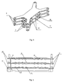
Fig. 1 is a perspective view schematically showing a heat dissipating device for a battery pack according to the present invention; -
Fig. 2 is a cross sectional view showing a heat dissipating device for a battery pack according to the present invention; -
Fig. 3 is a cross sectional view showing another heat dissipating device for a battery pack according to the present invention; -
Fig. 4 is a perspective view schematically showing a heat dissipating plate used with a heat dissipating device for a battery pack according to the present invention; -
Fig. 5 is a perspective view schematically showing a battery pack according to the present invention; -
Fig. 6 is a cross sectional view showing a battery pack according to the present invention; -
Fig. 7 is a cross sectional view showing another battery pack according to the present invention; -
Fig. 8 is a cross sectional view showing yet another battery pack according to the present invention; and -
Fig. 9 is a view schematically showing the structure of a supporting frame. -
1 heat pipe 2 heat collecting plate 3 heat dissipating plate 4 cell 5 supporting frame 6 bolt 11 bottom heat collecting plate 12 upper heat collecting plate 13 hole 14 heat sink 15 connecting piece 16 beam 17 retaining slot 18 projection 19 groove - Hereinafter, the heat dissipating device for a battery pack and the battery package using the same according to the present invention will be described in detail with reference to the drawings.
- As shown in
Fig. 1 and 2 , the present heat dissipating device for a battery pack comprises aheat pipe 1 and aheat collecting plate 2 comprising a bottomheat collecting plate 11 and an upperheat collecting plate 12 each of which has ahole 13 formed therein, and one end of theheat pipe 1 is inserted into thehole 13 of the bottomheat collecting plate 11 and the other end is inserted into thehole 13 of the upperheat collecting plate 12. - According to the present heat dissipating device, the
heat pipe 1 is an element with high heat conductivity. The heat pipe is mainly constructed as a closed hollow pipe having a capillary core which contains liquid therein and is extended axially along the inner wall of the pipe. The interior of the pipe is vacuumed previously, so that in the pipe there is only saturated vapor in equilibrium with the liquid. If one end of the heat pipe is placed at a high temperature position, and the other end at a low temperature position, the liquid at one end (hot end) will vaporize rapidly, causing the saturated vapor pressure at the hot end higher than that at the other end (cool end). Then the saturated vapor flows from the hot end to the cool end, condenses at the cool end and releases or dissipates heat of evaporation. And then, the condensed liquid comes back to the hot end by means of the capillary action. Since the heat can be conducted from the hot end to the cold end repeatedly, the heat pipe can be used as an excellent heat conductor. - The present invention does not intend to limit the
heat pipe 1 to any specific shapes. According to one embodiment of the present invention, as shown inFig. 1 , theheat pipe 1 may be designed as a U-shaped heat pipe, of which one end is inserted in the hole of the bottomheat collecting plate 11, and the other end is inserted in the hole of the upperheat collecting plate 12. In this embodiment, since the U-shaped heat pipe is used to transmit the heat from the upperheat collecting plate 12 to the bottomheat collecting plate 11, the size of the heat dissipating device can be reduced while the heat is transmitted rapidly and efficiently. - The present invention does not intend to limit the cross-section of the
heat pipe 1 to any specific shapes. According to one embodiment of the present invention, the cross-section of theheat pipe 1 may have a rectangular shape, and at this time the cross-section of theholes 13 retaining the ends of the heat pipe may also have a rectangular shape. In this embodiment, since the cross-section of the heat pipe has a rectangular shape, the thickness of theheat collecting plate 2 can be minimized on the premise that there is sufficient contact area between theheat pipe 1 and theheat collecting plate 2 to transmit heat generated by the battery pack, such that it is possible to reduce the whole size of the heat dissipating device and the battery pack using the same; and to increase the energy density of the battery pack. - According to the present invention, the number of the
heat pipe 1 is not specially limited, and may be increased or decreased in practice. However, at least oneheat pipe 1 should be provided for each upperheat collecting plate 12. If the amount of the heat generated by the battery pack is small, only oneheat pipe 1 may be provided for each upperheat collecting plate 12; while if large, two ormore heat pipes 1 may be provided. Of course, the more heat pipes are used, the more complicate and expensive the heat dissipating device will become. It is apparent for a person skilled in the art to select an appropriate number of heat pipes in practice. - The present invention does not intend to limit the
heat collecting plate 2 to any specific materials. Preferably, theheat collecting plate 2 can be made of the materials with excellent heat conductivity, such as aluminum alloy or copper alloy. Theheat collecting plate 2 comprises the bottomheat collecting plate 11 and upperheat collecting plate 12. In the present invention, the number of the upperheat collecting plate 12 is not specially limited, and may be increased or decreased in practice, but preferably is more than one. As shown inFig. 1 , there are two upperheat collecting plates 12. - The present invention does not intend to limit the
hole 13 in theheat collecting plate 2 to any specific size. Preferably, the cross-section of thehole 13 is fitting to or slightly bigger than that of theheat pipe 1. The ends of theheat pipe 1 may be coated with a heat conductive silica gel before being inserted into the holes, so as to enhance the connection strength therebetween. - According to the present invention, the number of the
hole 13 is not specially limited. Preferably, the number of theholes 13 in each upperheat collecting plate 12 is equal to that of theheat pipes 1 provided for the same, and the number of theholes 13 in the bottomheat collecting plate 11 is equal to the total number of theheat pipes 1 used in the heat dissipating device. If there are a plurality of holes in the bottomheat collecting plate 11, these holes may be designed in parallel with each other. Preferably, these holes may be arranged in parallel at the same or different height based on the bottom surface of the bottomheat collecting plate 11, and preferably at the same height. - According to one preferred embodiment, a
projection 18 and/or agroove 19 are provided on the upper surface of the bottomheat collecting plate 11 and on the surface of the upperheat collecting plate 12. Theprojection 18 and/or groove 19 are provided on one of or preferably both of the surfaces facing to each other of two adjacent heat collecting plates. Theprojection 18 and/or groove 19 can be provided on one surface or both surfaces of each heat collecting plate. For example, as shown inFig. 1 and 2 , the projection is provided on the upper surface of the bottomheat collecting plate 11, on the bottom surface of the top upperheat collecting plate 12, and on both surfaces of the middle upperheat collecting plate 12. - As shown in
Fig. 1 and 2 , there isprojection 18 on the upper surface of the bottomheat collecting plate 11 and on the surface of the upperheat collecting plate 12. The number of theprojection 18 is preferably more than one, and theseprojections 18 are preferably arranged longitudinally in parallel. Where the heat dissipating device is used for a battery pack which comprises a cell having grooves on its surfaces, the projections can mate with the grooves of each cell. - As shown in
Fig. 3 , there isgroove 19 on the upper surface of the bottomheat collecting plate 11 and on the surface of the upperheat collecting plate 12. The number of thegroove 19 is preferably more than one, and these grooves are preferably arranged longitudinally in parallel. Where the heat dissipating device is used for a battery pack which comprises a cylindrical cell, the projections can mate with the surface of the cylindrical cell. - During the operation of the present heat dissipating device, the above embodiment can not only provide sufficient contact area between the heat collecting plate and the cell to efficiently transmit heat generated by the cell, but also provide the positioning accuracy and the fix strength when assembling the cell, and as a result both the safety property and the heat dissipating property of the battery pack using the heat dissipating device can be improved.
- According to the heat dissipating device of the present invention, a heat dissipating structure, which is a
heat sink 14 or aheat dissipating plate 3, may be provided under the lower surface of the bottom heat collecting plate. - The
heat sink 14 can increase the heat dissipating area of the bottomheat collecting plate 11, and enhance the heat dissipating efficiency. The number and mounting manners of theheat sink 14 may vary in practice. For example, theheat sink 14 may be longitudinally disposed on the lower surface of the bottomheat collecting plate 11. - A
heat dissipating plate 3 may be provided under the bottomheat collecting plate 11, and the upper surface of theheat dissipating plate 3 contacts closely with the lower surface of the bottomheat collecting plate 11, such that the heat can be transmitted efficiently from the bottomheat collecting plate 11 to theheat dissipating plate 3. - According to the present invention, the
heat dissipating plate 3 can be made of various materials with good heat conductivity, for example but not limited to, aluminum alloy and copper alloy. As shown inFig. 4 , theheat sink 14 is provided on the lower surface of theheat dissipating plate 3 to increase the heat dissipating area of theheat dissipating plate 3 and enhance the heat dissipating efficiency. According to the present invention, the number and mounting manners of theheat sink 14 may vary in practice. For example, as shown inFig. 4 , theheat sink 14 may be longitudinally disposed on the lower surface of theheat dissipating plate 3. According to the present invention, the number of the heat dissipating plate is not specially limited, and may be equal to the number of the bottom heat collecting plate. - As shown in
Fig. 5 and 6 , the present battery pack comprises a plurality ofcells 4 connected in series or in parallel and a heat dissipating device which comprises aheat pipe 1 and aheat collecting plate 2. Theheat collecting plate 2 includes the bottomheat collecting plate 11 and the upperheat collecting plate 12, and thecell 4 are provided between the bottomheat collecting plate 11 and the upperheat collecting plate 12. The bottomheat collecting plate 11 and the upperheat collecting plate 12 each has ahole 13 therein, and two ends of theheat pipe 1 are inserted respectively into theholes 13 of the bottomheat collecting plate 11 and the upperheat collecting plate 12. - When there are a plurality of upper
heat collecting plates 12, thecells 4 are disposed between the bottomheat collecting plate 11 and the adjacent upperheat collecting plate 12, and between two adjacent upperheat collecting plates 12. That is, the cells are disposed between each two adjacent heat collecting plates. - The heat pipe, the heat collecting plate and the hole formed in the plate have been described in detail above, and more details are omitted here.
- As shown in
Fig. 5 , the plurality ofcells 4 can be connected in series or in parallel by means of a connectingpiece 15 used in the conventional battery pack. - As shown in
Fig. 5 , the present battery pack may further comprise a supportingframe 5 on which theheat collecting plate 2 may be mounted by any known means. For example, in one embodiment of the present invention, theheat collecting plate 2 and the supportingframe 5 respectively have a through hole therein, and abolt 6 is provided to insert through the through hole and fastened by a nut. Thebolt 6 is preferably a stepped bolt. In this embodiment, eachcell 4 is positioned between two adjacent heat collecting plates which are connected by the stepped bolt, such that the cell can be mounted stably between the two plates without any pressure stress to prevent the cells from shifting by the shock of outside force in case of concussion and the like, the short circuit in the battery pack can be avoided, and the mechanical safety of the battery pack is thus enhanced. - Preferably, the contacting surfaces between the
cells 4 and the upper and bottom heat collecting plates may be coated with a heat conductive adhesive, which not only enhances the connection strength between the plates and the cells to improve the mechanical safety property of the present battery pack, but also conducts the heat generated by the cells to the heat collecting plate to increase the heat dissipating efficiency. Any known heat conductive adhesive may be used, and preferably heat conductive silica gel is used as the heat conductive adhesive. - As shown in
Fig. 9 , the supportingframe 5 may comprise threeparallel beams 16 and two fixinggrooves 17 between thebeams 16. As shown inFig. 6 and7 , theheat dissipating plate 3 is provided under the lower surface of the bottomheat collecting plate 11. Theheat dissipating plate 3 can be mounted on the supportingframe 5 by means of the fixinggroove 17, and then the bottomheat collecting plate 11 is mounted on theheat dissipating plate 3. - According to the present invention, various kinds of cells can be used in the battery pack, for example but not limited to, alkaline secondary cells such as Ni-Cd, Ni-Zn and Ni-MH cells, and lithium-ion cells.
- The present invention does not intend to limit the cells and the heat collecting plates to any specific number or quantity. As shown in
Fig. 6 and7 , there are 8 cells divided into two layers, 6 heat collecting plates divided into three layers (2 bottom heat collecting plates of one layer, and 4 upper heat collecting plates divided into two layers), and 2 heat dissipating plates. As shown inFig. 8 , there are 40 cells divided into two layers, 6 heat collecting plates divided into three layers (2 bottom heat collecting plates of one layer, and 4 upper heat collecting plates divided into two layers), and 2 heat dissipating plates. - The present invention does not intend to limit the cell to any specific shapes. The cell may be shaped as a hexagonal combined body as shown in
Fig. 6 , a rectangular single body as shown inFig. 7 , or a cylindrical single body as shown inFig. 8 . - According to one embodiment of the present invention, as shown in
Fig. 6 , thecell 4 has grooves on its surface, and the bottomheat collecting plate 11 and the upperheat collecting plate 12 haveprojections 18 mating with the grooves on their surfaces contacting with thecell 4. Theprojections 18 may be formed on either or both of the opposite surfaces of two adjacent heat collecting plates contacting with thesame cell 4, and preferably on both of the opposite surfaces. - According to another embodiment of the present invention, as shown in
Fig. 8 , thecell 4 is the cylinder single cell, and the bottomheat collecting plate 11 and the upperheat collecting plate 12 havegrooves 19 mating with the surface of the cylinder cell. Thegrooves 19 may be formed on either or both of the opposite surfaces of two adjacent heat collecting plates contacting with thesame cell 4, and preferably on both of the opposite surfaces. - In the above two embodiments, there is sufficient contacting area between the
heat collecting plate 2 and thecell 4 to transmit the heat generated by the cell, and at the same time the positioning accuracy and the fix strength can be enhanced during assembling the cell. - Hereinafter, the assemble procedure of the battery pack of the present invention will be described with reference to the battery pack shown in
Fig. 6 . - 1, placing two
heat dissipating plates 3 respectively into the fixinggrooves 17 of the supporting frame 8; inserting six bolts 5 (stepped bolts) through the holes of thebeams 16, mounting two bottomheat collecting plates 11 respectively onto the twoheat dissipating plate 3 by means of the first stage of the stepped bolts; and then fixing them by fastening the first nuts on the stepped bolts; - 2, coating the upper surface of the bottom
heat collecting plate 11 with heat conductive silica gel; placing fourcells 4 onto the bottomheat collecting plate 11 in alignment with theprojections 18 thereon; coating the surface of thecells 4 with heat conductive silica gel; placing two upperheat collecting plate 12 onto thecells 4 in alignment with the grooves of thecells 4; and then fastening the second nuts on the stepped bolts; - 3, repeating the
above step 2, placing the second layer of cells, placing the upper heat collecting plates onto the second layer of cells, and fastening the third nuts on the stepped bolts; - 4, selecting a heat pipe with an appropriate length based on distances between the upper heat collecting plates and the bottom heat collecting plate, and bending the heat pipe into U-shape;
- 5, coating the surface of the two ends of the U-shaped heat pipe with heat conductive silica gel, and inserting both ends into corresponding holes with predetermined depth in the upper and bottom heat collecting plates before the silica gel hardens;
- 6, repeating
steps - 7, repeating
step 6 until all heat pipes are assembled; and - 8, connecting all the
cells 4 together with connectingpieces 15, to form a battery pack.
Claims (14)
- A heat dissipating device for a battery pack, comprising:a heat pipe (1); anda heat collecting plate (2) comprising a bottom heat collecting plate (11) and a upper heat collecting plate (12) which both have a hole (13) formed therein;wherein, two ends of the heat pipe (1) are inserted respectively into the holes (13) of the bottom heat collecting plate (11) and the upper heat collecting plate (12).
- The heat dissipating device as claimed in claim 1, wherein,
the number of the upper heat collecting plate (12) is more than one and each upper heat collecting plate (12) has at least one hole;
the bottom heat collecting plate (11) has more than one hole therein; and
the heat pipe (1) is U-shaped, and one end of each U-shaped heat pipe is inserted into one hole of the bottom heat collecting plate (11) and the other end is inserted into one hole of the upper heat collecting plate (12). - The heat dissipating device as claimed in claim 2, wherein,
the number of the holes in the bottom heat collecting plate (11) is equal to the number of the U-shaped heat pipe (1); and
the holes in the bottom heat collecting plate (11) are parallel with each other. - The heat dissipating device as claimed in claim 1, wherein,
the bottom heat collecting plate (11) has at least one projection (18) and/or a groove (19) on its upper surface, and
the upper heat collecting plate (12) has at least one projection (18) and/or a groove (19) on its surface. - The heat dissipating device as claimed in claim 4, wherein,
the number of the projection (18) and/or groove (19) is more than one; and
these projections (18) and/or grooves (19) are arranged longitudinally in parallel along with the upper surface of the bottom heat collecting plate (11) and the surface of the upper heat collecting plate (12). - The heat dissipating device as claimed in claim 1, wherein,
a heat dissipating structure, which is a heat sink (14) or a heat dissipating plate (3), is provided under the lower surface of the bottom heat collecting plate (1),. - A battery pack comprising a plurality of cells (4) connected in series or in parallel, characterized in that, it further comprises a heat dissipating device which comprises:a heat pipe (1); anda heat collecting plate (2) comprising a bottom heat collecting plate (11) and a upper heat collecting plate (12) which both have a hole (13) formed therein, and between which the cells (4) are interposed;wherein, two ends of the heat pipe are inserted respectively into the holes (13) of the bottom heat collecting plate and the upper heat collecting plate.
- The battery pack as claimed in claim 7, wherein,
the number of the upper heat collecting plate (12) is more than one and each upper heat collecting plate (12) has at least one hole;
the cells (4) are interposed between the bottom heat collecting plate (11) and one adjacent upper heat collecting plate (12), and between two adjacent upper heat collecting plates (12);
the bottom heat collecting plate (11) has more than ones holes therein; and
the heat pipe (1) is U-shaped, and one end of each U-shaped heat pipe is inserted into one hole of the bottom heat collecting plate (11) and the other end is inserted into one hole of the upper heat collecting plate (12). - The battery pack as claimed in claim 8, wherein,
the number of the holes in the bottom heat collecting plate (11) is equal to the number of the U-shaped heat pipe (1); and
the holes in the bottom heat collecting plate (11) are parallel with each other. - The battery pack as claimed in claim 7, wherein,
a heat dissipating structure, which is a heat sink (14) or a heat dissipating plate (3), is provided under the lower surface of the bottom heat collecting plate (1). - The battery pack as claimed in claim 7, further comprising:a supporting frame (5) on which the heat collecting plate (2) is fixed.
- The battery pack as claimed in claim 7, wherein,
the contacting surfaces between the cells (4) and the bottom and upper heat collecting plates are coated with a heat conductive adhesive. - The battery pack as claimed in claim 7, wherein,
the cells (4) have grooves on the surface thereof; and
the bottom and upper heat collecting plates have projections (18) mating with the grooves on their surfaces contacting with the cells (4). - The battery pack as claimed in claim 7, wherein,
the cells (4) are cylindrical cells; and
the bottom and upper heat collecting plates have grooves (19) mating with the surface of the cylindrical cells on their surfaces contacting with the cells (4).
Applications Claiming Priority (3)
| Application Number | Priority Date | Filing Date | Title |
|---|---|---|---|
| CNB2005101157059A CN100487973C (en) | 2005-11-08 | 2005-11-08 | Power battery pack |
| CNB200610066527XA CN100517860C (en) | 2006-03-30 | 2006-03-30 | Heat sink for power battery pack and power battery pack |
| PCT/CN2006/000899 WO2007053992A1 (en) | 2005-11-08 | 2006-05-08 | A heat dissipating device for a battery pack, and a battery pack using the same |
Publications (3)
| Publication Number | Publication Date |
|---|---|
| EP1932204A1 EP1932204A1 (en) | 2008-06-18 |
| EP1932204A4 EP1932204A4 (en) | 2008-08-27 |
| EP1932204B1 true EP1932204B1 (en) | 2010-11-17 |
Family
ID=38022961
Family Applications (1)
| Application Number | Title | Priority Date | Filing Date |
|---|---|---|---|
| EP20060741795 Expired - Lifetime EP1932204B1 (en) | 2005-11-08 | 2006-05-08 | A heat dissipating device for a battery pack, and a battery pack using the same |
Country Status (8)
| Country | Link |
|---|---|
| US (1) | US8574739B2 (en) |
| EP (1) | EP1932204B1 (en) |
| JP (1) | JP5072852B2 (en) |
| KR (1) | KR101029353B1 (en) |
| AT (1) | ATE488879T1 (en) |
| CA (1) | CA2628870C (en) |
| DE (1) | DE602006018336D1 (en) |
| WO (1) | WO2007053992A1 (en) |
Families Citing this family (18)
| Publication number | Priority date | Publication date | Assignee | Title |
|---|---|---|---|---|
| US9113577B2 (en) * | 2001-11-27 | 2015-08-18 | Thermotek, Inc. | Method and system for automotive battery cooling |
| DE102009004543A1 (en) | 2009-01-14 | 2010-07-15 | Bayerische Motoren Werke Aktiengesellschaft | Device for powering a motor vehicle with optimized heat dissipation |
| KR101057558B1 (en) * | 2010-01-27 | 2011-08-17 | 에스비리모티브 주식회사 | Battery pack |
| CN102013463B (en) * | 2010-09-08 | 2013-11-13 | 深圳市智优电池集成技术有限公司 | Heat radiation frame for mounting of battery pack |
| KR101201742B1 (en) * | 2010-11-05 | 2012-11-15 | 에스비리모티브 주식회사 | Battery module |
| DE102011077924A1 (en) * | 2011-06-21 | 2012-12-27 | Robert Bosch Gmbh | Storage unit for storing electrical energy with a heat pipe |
| TWI528614B (en) * | 2013-09-25 | 2016-04-01 | 原瑞電池科技股份有限公司 | Battery module |
| US11309604B2 (en) | 2015-04-13 | 2022-04-19 | Cps Technology Holdings Llc | Thermal epoxy and positioning of electrochemical cells |
| KR101727109B1 (en) | 2015-07-03 | 2017-04-17 | 에스앤지 주식회사 | Plate heat exchanger integrated pipeline |
| US11543188B2 (en) * | 2016-06-15 | 2023-01-03 | Delta Electronics, Inc. | Temperature plate device |
| KR102345048B1 (en) | 2018-09-04 | 2021-12-28 | 주식회사 엘지에너지솔루션 | Secondary Battery Pack Having Radiant Heat Plate |
| DE102018123707B4 (en) | 2018-09-26 | 2022-07-07 | Dr. Ing. H.C. F. Porsche Aktiengesellschaft | battery setup |
| CN109216828B (en) * | 2018-10-12 | 2024-05-14 | 广东工业大学 | Power battery heat abstractor based on pulsation heat pipe |
| KR102851862B1 (en) * | 2021-04-02 | 2025-08-28 | 에스케이하이닉스 주식회사 | Heat dissipation module |
| DE102022111446A1 (en) | 2022-05-09 | 2023-11-09 | Dr. Ing. H.C. F. Porsche Aktiengesellschaft | Battery arrangement with capillary arrangements |
| KR102903912B1 (en) * | 2022-09-30 | 2025-12-24 | 장성호 | cooling device using flexible Peltier element |
| CN117428437A (en) * | 2023-11-28 | 2024-01-23 | 江苏精研科技股份有限公司 | A method for preparing a three-dimensional capillary core structure heat sink |
| CN117913416A (en) * | 2023-12-21 | 2024-04-19 | 浙江凌骁能源科技有限公司 | Side-standing cold plate, side-standing cold plate processing method and battery pack |
Family Cites Families (19)
| Publication number | Priority date | Publication date | Assignee | Title |
|---|---|---|---|---|
| JPH08111244A (en) * | 1994-10-12 | 1996-04-30 | Nissan Motor Co Ltd | Stacked battery device |
| JP3451142B2 (en) * | 1994-11-18 | 2003-09-29 | 本田技研工業株式会社 | Battery assembly with temperature control mechanism |
| JPH09326266A (en) * | 1996-06-06 | 1997-12-16 | Furukawa Electric Co Ltd:The | Heat dissipation device for power storage batteries |
| JPH09326264A (en) * | 1996-06-06 | 1997-12-16 | Furukawa Electric Co Ltd:The | Heat dissipation device for power storage batteries |
| US6653002B1 (en) * | 1997-05-09 | 2003-11-25 | Ronald J. Parise | Quick charge battery with thermal management |
| JPH11329485A (en) * | 1998-05-14 | 1999-11-30 | Tokyo Electric Power Co Inc:The | Battery module for power storage |
| US6045331A (en) * | 1998-08-10 | 2000-04-04 | Gehm; William | Fluid pump speed controller |
| JP2001255085A (en) * | 2000-03-14 | 2001-09-21 | Hitachi Ltd | Variable conductance heat pipe |
| JP2001297740A (en) * | 2000-04-12 | 2001-10-26 | Matsushita Electric Ind Co Ltd | Battery module mounting frame and battery module mounting method using the same |
| JP4079572B2 (en) * | 2000-04-14 | 2008-04-23 | 松下電器産業株式会社 | Battery pack |
| JP2002124225A (en) * | 2000-10-16 | 2002-04-26 | Toshiba Battery Co Ltd | Battery pack |
| JP3764332B2 (en) * | 2000-10-26 | 2006-04-05 | 松下電器産業株式会社 | Battery pack |
| CN2450785Y (en) | 2000-11-17 | 2001-09-26 | 天津和平海湾电源集团有限公司 | Square seal cell fastening assembling structure |
| TW501293B (en) * | 2001-01-06 | 2002-09-01 | Acer Inc | Method and device to raise the battery efficiency of portable electronic device |
| JP2003346921A (en) * | 2002-05-24 | 2003-12-05 | Matsushita Electric Ind Co Ltd | Storage battery |
| JP2004146161A (en) * | 2002-10-23 | 2004-05-20 | Sony Corp | battery pack |
| JP4440553B2 (en) * | 2003-03-11 | 2010-03-24 | パナソニックEvエナジー株式会社 | Battery pack cooling device |
| US7270910B2 (en) * | 2003-10-03 | 2007-09-18 | Black & Decker Inc. | Thermal management systems for battery packs |
| CN2713633Y (en) * | 2004-05-21 | 2005-07-27 | 鸿富锦精密工业(深圳)有限公司 | Heat pipe radiator assembly |
-
2006
- 2006-05-08 US US12/092,564 patent/US8574739B2/en not_active Expired - Fee Related
- 2006-05-08 KR KR1020087010336A patent/KR101029353B1/en not_active Expired - Fee Related
- 2006-05-08 WO PCT/CN2006/000899 patent/WO2007053992A1/en not_active Ceased
- 2006-05-08 EP EP20060741795 patent/EP1932204B1/en not_active Expired - Lifetime
- 2006-05-08 AT AT06741795T patent/ATE488879T1/en not_active IP Right Cessation
- 2006-05-08 CA CA 2628870 patent/CA2628870C/en not_active Expired - Lifetime
- 2006-05-08 JP JP2008539211A patent/JP5072852B2/en not_active Expired - Fee Related
- 2006-05-08 DE DE200660018336 patent/DE602006018336D1/en not_active Expired - Lifetime
Also Published As
| Publication number | Publication date |
|---|---|
| CA2628870A1 (en) | 2007-05-18 |
| US8574739B2 (en) | 2013-11-05 |
| KR101029353B1 (en) | 2011-04-13 |
| JP2009515305A (en) | 2009-04-09 |
| ATE488879T1 (en) | 2010-12-15 |
| DE602006018336D1 (en) | 2010-12-30 |
| US20080292949A1 (en) | 2008-11-27 |
| KR20080066931A (en) | 2008-07-17 |
| JP5072852B2 (en) | 2012-11-14 |
| CA2628870C (en) | 2011-02-22 |
| WO2007053992A1 (en) | 2007-05-18 |
| EP1932204A1 (en) | 2008-06-18 |
| EP1932204A4 (en) | 2008-08-27 |
Similar Documents
| Publication | Publication Date | Title |
|---|---|---|
| EP1932204B1 (en) | A heat dissipating device for a battery pack, and a battery pack using the same | |
| EP2814089B1 (en) | Battery pack with a bus bar having novel structure | |
| JP4079572B2 (en) | Battery pack | |
| JP5183172B2 (en) | Battery system | |
| CN103972610B (en) | The battery system of device with battery battery core and for regulating cell battery core temperature | |
| US20130164594A1 (en) | Electrical energy storage cell and apparatus | |
| JP2013157111A (en) | Cooling and heating structure of battery pack | |
| EP1935050B1 (en) | A heat dissipating device for a battery pack, and a battery pack using the same | |
| CN103518274A (en) | Energy storage device | |
| JP6412456B2 (en) | Secondary battery cooling system | |
| JP2002134177A (en) | Battery pack | |
| CN103620863A (en) | Energy storage device with temperature controlling means | |
| JP2018088305A (en) | Cooling system | |
| CN117317446A (en) | A kind of vapor chamber and battery component | |
| JP6065738B2 (en) | Battery pack | |
| JP2025518420A (en) | Thermal fin for battery device and battery module with thermal fin | |
| CN114400398B (en) | A heat dissipation component and battery pack for mounting battery modules | |
| KR102328975B1 (en) | Battery module | |
| CN116131045B (en) | Busbars, battery modules, battery packs and new energy vehicles | |
| CN214014800U (en) | Heat radiation module | |
| CN113675494B (en) | A heat pipe fin cooling structure applied to power battery modules | |
| JP7683233B2 (en) | Battery pack | |
| CN223245695U (en) | Battery cell module and new energy automobile | |
| CN117855676A (en) | Battery packs, energy storage devices and electrical equipment | |
| KR20240037111A (en) | Cell heat dissipation battery module |
Legal Events
| Date | Code | Title | Description |
|---|---|---|---|
| PUAI | Public reference made under article 153(3) epc to a published international application that has entered the european phase |
Free format text: ORIGINAL CODE: 0009012 |
|
| 17P | Request for examination filed |
Effective date: 20080409 |
|
| AK | Designated contracting states |
Kind code of ref document: A1 Designated state(s): AT BE BG CH CY CZ DE DK EE ES FI FR GB GR HU IE IS IT LI LT LU LV MC NL PL PT RO SE SI SK TR |
|
| A4 | Supplementary search report drawn up and despatched |
Effective date: 20080730 |
|
| 17Q | First examination report despatched |
Effective date: 20090417 |
|
| GRAP | Despatch of communication of intention to grant a patent |
Free format text: ORIGINAL CODE: EPIDOSNIGR1 |
|
| DAX | Request for extension of the european patent (deleted) | ||
| GRAS | Grant fee paid |
Free format text: ORIGINAL CODE: EPIDOSNIGR3 |
|
| GRAA | (expected) grant |
Free format text: ORIGINAL CODE: 0009210 |
|
| AK | Designated contracting states |
Kind code of ref document: B1 Designated state(s): AT BE BG CH CY CZ DE DK EE ES FI FR GB GR HU IE IS IT LI LT LU LV MC NL PL PT RO SE SI SK TR |
|
| REG | Reference to a national code |
Ref country code: GB Ref legal event code: FG4D |
|
| REG | Reference to a national code |
Ref country code: CH Ref legal event code: EP |
|
| REG | Reference to a national code |
Ref country code: IE Ref legal event code: FG4D |
|
| REF | Corresponds to: |
Ref document number: 602006018336 Country of ref document: DE Date of ref document: 20101230 Kind code of ref document: P |
|
| REG | Reference to a national code |
Ref country code: NL Ref legal event code: VDEP Effective date: 20101117 |
|
| LTIE | Lt: invalidation of european patent or patent extension |
Effective date: 20101117 |
|
| PG25 | Lapsed in a contracting state [announced via postgrant information from national office to epo] |
Ref country code: LT Free format text: LAPSE BECAUSE OF FAILURE TO SUBMIT A TRANSLATION OF THE DESCRIPTION OR TO PAY THE FEE WITHIN THE PRESCRIBED TIME-LIMIT Effective date: 20101117 |
|
| PG25 | Lapsed in a contracting state [announced via postgrant information from national office to epo] |
Ref country code: SE Free format text: LAPSE BECAUSE OF FAILURE TO SUBMIT A TRANSLATION OF THE DESCRIPTION OR TO PAY THE FEE WITHIN THE PRESCRIBED TIME-LIMIT Effective date: 20101117 Ref country code: CY Free format text: LAPSE BECAUSE OF FAILURE TO SUBMIT A TRANSLATION OF THE DESCRIPTION OR TO PAY THE FEE WITHIN THE PRESCRIBED TIME-LIMIT Effective date: 20101117 Ref country code: NL Free format text: LAPSE BECAUSE OF FAILURE TO SUBMIT A TRANSLATION OF THE DESCRIPTION OR TO PAY THE FEE WITHIN THE PRESCRIBED TIME-LIMIT Effective date: 20101117 Ref country code: BG Free format text: LAPSE BECAUSE OF FAILURE TO SUBMIT A TRANSLATION OF THE DESCRIPTION OR TO PAY THE FEE WITHIN THE PRESCRIBED TIME-LIMIT Effective date: 20110217 Ref country code: LV Free format text: LAPSE BECAUSE OF FAILURE TO SUBMIT A TRANSLATION OF THE DESCRIPTION OR TO PAY THE FEE WITHIN THE PRESCRIBED TIME-LIMIT Effective date: 20101117 Ref country code: AT Free format text: LAPSE BECAUSE OF FAILURE TO SUBMIT A TRANSLATION OF THE DESCRIPTION OR TO PAY THE FEE WITHIN THE PRESCRIBED TIME-LIMIT Effective date: 20101117 Ref country code: IS Free format text: LAPSE BECAUSE OF FAILURE TO SUBMIT A TRANSLATION OF THE DESCRIPTION OR TO PAY THE FEE WITHIN THE PRESCRIBED TIME-LIMIT Effective date: 20110317 Ref country code: SI Free format text: LAPSE BECAUSE OF FAILURE TO SUBMIT A TRANSLATION OF THE DESCRIPTION OR TO PAY THE FEE WITHIN THE PRESCRIBED TIME-LIMIT Effective date: 20101117 Ref country code: FI Free format text: LAPSE BECAUSE OF FAILURE TO SUBMIT A TRANSLATION OF THE DESCRIPTION OR TO PAY THE FEE WITHIN THE PRESCRIBED TIME-LIMIT Effective date: 20101117 Ref country code: PT Free format text: LAPSE BECAUSE OF FAILURE TO SUBMIT A TRANSLATION OF THE DESCRIPTION OR TO PAY THE FEE WITHIN THE PRESCRIBED TIME-LIMIT Effective date: 20110317 |
|
| PG25 | Lapsed in a contracting state [announced via postgrant information from national office to epo] |
Ref country code: GR Free format text: LAPSE BECAUSE OF FAILURE TO SUBMIT A TRANSLATION OF THE DESCRIPTION OR TO PAY THE FEE WITHIN THE PRESCRIBED TIME-LIMIT Effective date: 20110218 |
|
| PG25 | Lapsed in a contracting state [announced via postgrant information from national office to epo] |
Ref country code: BE Free format text: LAPSE BECAUSE OF FAILURE TO SUBMIT A TRANSLATION OF THE DESCRIPTION OR TO PAY THE FEE WITHIN THE PRESCRIBED TIME-LIMIT Effective date: 20101117 Ref country code: ES Free format text: LAPSE BECAUSE OF FAILURE TO SUBMIT A TRANSLATION OF THE DESCRIPTION OR TO PAY THE FEE WITHIN THE PRESCRIBED TIME-LIMIT Effective date: 20110228 Ref country code: CZ Free format text: LAPSE BECAUSE OF FAILURE TO SUBMIT A TRANSLATION OF THE DESCRIPTION OR TO PAY THE FEE WITHIN THE PRESCRIBED TIME-LIMIT Effective date: 20101117 Ref country code: EE Free format text: LAPSE BECAUSE OF FAILURE TO SUBMIT A TRANSLATION OF THE DESCRIPTION OR TO PAY THE FEE WITHIN THE PRESCRIBED TIME-LIMIT Effective date: 20101117 |
|
| PG25 | Lapsed in a contracting state [announced via postgrant information from national office to epo] |
Ref country code: DK Free format text: LAPSE BECAUSE OF FAILURE TO SUBMIT A TRANSLATION OF THE DESCRIPTION OR TO PAY THE FEE WITHIN THE PRESCRIBED TIME-LIMIT Effective date: 20101117 Ref country code: PL Free format text: LAPSE BECAUSE OF FAILURE TO SUBMIT A TRANSLATION OF THE DESCRIPTION OR TO PAY THE FEE WITHIN THE PRESCRIBED TIME-LIMIT Effective date: 20101117 Ref country code: RO Free format text: LAPSE BECAUSE OF FAILURE TO SUBMIT A TRANSLATION OF THE DESCRIPTION OR TO PAY THE FEE WITHIN THE PRESCRIBED TIME-LIMIT Effective date: 20101117 Ref country code: SK Free format text: LAPSE BECAUSE OF FAILURE TO SUBMIT A TRANSLATION OF THE DESCRIPTION OR TO PAY THE FEE WITHIN THE PRESCRIBED TIME-LIMIT Effective date: 20101117 |
|
| PLBE | No opposition filed within time limit |
Free format text: ORIGINAL CODE: 0009261 |
|
| STAA | Information on the status of an ep patent application or granted ep patent |
Free format text: STATUS: NO OPPOSITION FILED WITHIN TIME LIMIT |
|
| 26N | No opposition filed |
Effective date: 20110818 |
|
| REG | Reference to a national code |
Ref country code: DE Ref legal event code: R097 Ref document number: 602006018336 Country of ref document: DE Effective date: 20110818 |
|
| PG25 | Lapsed in a contracting state [announced via postgrant information from national office to epo] |
Ref country code: IT Free format text: LAPSE BECAUSE OF FAILURE TO SUBMIT A TRANSLATION OF THE DESCRIPTION OR TO PAY THE FEE WITHIN THE PRESCRIBED TIME-LIMIT Effective date: 20101117 Ref country code: MC Free format text: LAPSE BECAUSE OF NON-PAYMENT OF DUE FEES Effective date: 20110531 |
|
| REG | Reference to a national code |
Ref country code: CH Ref legal event code: PL |
|
| PG25 | Lapsed in a contracting state [announced via postgrant information from national office to epo] |
Ref country code: CH Free format text: LAPSE BECAUSE OF NON-PAYMENT OF DUE FEES Effective date: 20110531 Ref country code: LI Free format text: LAPSE BECAUSE OF NON-PAYMENT OF DUE FEES Effective date: 20110531 |
|
| REG | Reference to a national code |
Ref country code: IE Ref legal event code: MM4A |
|
| PG25 | Lapsed in a contracting state [announced via postgrant information from national office to epo] |
Ref country code: IE Free format text: LAPSE BECAUSE OF NON-PAYMENT OF DUE FEES Effective date: 20110508 |
|
| PG25 | Lapsed in a contracting state [announced via postgrant information from national office to epo] |
Ref country code: LU Free format text: LAPSE BECAUSE OF NON-PAYMENT OF DUE FEES Effective date: 20110508 |
|
| PG25 | Lapsed in a contracting state [announced via postgrant information from national office to epo] |
Ref country code: TR Free format text: LAPSE BECAUSE OF FAILURE TO SUBMIT A TRANSLATION OF THE DESCRIPTION OR TO PAY THE FEE WITHIN THE PRESCRIBED TIME-LIMIT Effective date: 20101117 |
|
| PG25 | Lapsed in a contracting state [announced via postgrant information from national office to epo] |
Ref country code: HU Free format text: LAPSE BECAUSE OF FAILURE TO SUBMIT A TRANSLATION OF THE DESCRIPTION OR TO PAY THE FEE WITHIN THE PRESCRIBED TIME-LIMIT Effective date: 20101117 |
|
| REG | Reference to a national code |
Ref country code: FR Ref legal event code: PLFP Year of fee payment: 11 |
|
| REG | Reference to a national code |
Ref country code: FR Ref legal event code: PLFP Year of fee payment: 12 |
|
| REG | Reference to a national code |
Ref country code: FR Ref legal event code: PLFP Year of fee payment: 13 |
|
| PGFP | Annual fee paid to national office [announced via postgrant information from national office to epo] |
Ref country code: GB Payment date: 20220519 Year of fee payment: 17 Ref country code: FR Payment date: 20220523 Year of fee payment: 17 Ref country code: DE Payment date: 20220519 Year of fee payment: 17 |
|
| REG | Reference to a national code |
Ref country code: DE Ref legal event code: R119 Ref document number: 602006018336 Country of ref document: DE |
|
| GBPC | Gb: european patent ceased through non-payment of renewal fee |
Effective date: 20230508 |
|
| PG25 | Lapsed in a contracting state [announced via postgrant information from national office to epo] |
Ref country code: DE Free format text: LAPSE BECAUSE OF NON-PAYMENT OF DUE FEES Effective date: 20231201 Ref country code: GB Free format text: LAPSE BECAUSE OF NON-PAYMENT OF DUE FEES Effective date: 20230508 |
|
| PG25 | Lapsed in a contracting state [announced via postgrant information from national office to epo] |
Ref country code: FR Free format text: LAPSE BECAUSE OF NON-PAYMENT OF DUE FEES Effective date: 20230531 |