EP1931532B1 - Unite de transmission et d'entrainement presentant un tuyau support et procede de production d'une telle unite - Google Patents
Unite de transmission et d'entrainement presentant un tuyau support et procede de production d'une telle unite Download PDFInfo
- Publication number
- EP1931532B1 EP1931532B1 EP06763915A EP06763915A EP1931532B1 EP 1931532 B1 EP1931532 B1 EP 1931532B1 EP 06763915 A EP06763915 A EP 06763915A EP 06763915 A EP06763915 A EP 06763915A EP 1931532 B1 EP1931532 B1 EP 1931532B1
- Authority
- EP
- European Patent Office
- Prior art keywords
- carrier tube
- gearing
- drive assembly
- support element
- support tube
- Prior art date
- Legal status (The legal status is an assumption and is not a legal conclusion. Google has not performed a legal analysis and makes no representation as to the accuracy of the status listed.)
- Expired - Fee Related
Links
- 238000004519 manufacturing process Methods 0.000 title claims description 5
- 230000005540 biological transmission Effects 0.000 title abstract description 23
- 239000000463 material Substances 0.000 claims description 11
- 230000008878 coupling Effects 0.000 claims description 10
- 238000010168 coupling process Methods 0.000 claims description 10
- 238000005859 coupling reaction Methods 0.000 claims description 10
- 238000000034 method Methods 0.000 claims description 8
- 238000010079 rubber tapping Methods 0.000 claims description 4
- 229910000760 Hardened steel Inorganic materials 0.000 claims description 2
- 238000004026 adhesive bonding Methods 0.000 claims description 2
- 238000003780 insertion Methods 0.000 claims description 2
- 230000037431 insertion Effects 0.000 claims description 2
- 230000002787 reinforcement Effects 0.000 claims description 2
- 238000003466 welding Methods 0.000 claims description 2
- 230000000712 assembly Effects 0.000 claims 1
- 238000000429 assembly Methods 0.000 claims 1
- 238000006073 displacement reaction Methods 0.000 claims 1
- 230000036316 preload Effects 0.000 claims 1
- 230000015572 biosynthetic process Effects 0.000 description 3
- 238000005755 formation reaction Methods 0.000 description 3
- 230000002093 peripheral effect Effects 0.000 description 3
- 210000000078 claw Anatomy 0.000 description 2
- 238000007598 dipping method Methods 0.000 description 2
- 230000013011 mating Effects 0.000 description 2
- 238000003825 pressing Methods 0.000 description 2
- 206010039203 Road traffic accident Diseases 0.000 description 1
- 230000006978 adaptation Effects 0.000 description 1
- 230000004323 axial length Effects 0.000 description 1
- 238000005452 bending Methods 0.000 description 1
- 238000010276 construction Methods 0.000 description 1
- 230000001419 dependent effect Effects 0.000 description 1
- 238000002474 experimental method Methods 0.000 description 1
- 239000002184 metal Substances 0.000 description 1
- 238000000465 moulding Methods 0.000 description 1
- 230000001681 protective effect Effects 0.000 description 1
- 230000003014 reinforcing effect Effects 0.000 description 1
- 238000003860 storage Methods 0.000 description 1
- 238000003856 thermoforming Methods 0.000 description 1
Images


Classifications
-
- B—PERFORMING OPERATIONS; TRANSPORTING
- B60—VEHICLES IN GENERAL
- B60N—SEATS SPECIALLY ADAPTED FOR VEHICLES; VEHICLE PASSENGER ACCOMMODATION NOT OTHERWISE PROVIDED FOR
- B60N2/00—Seats specially adapted for vehicles; Arrangement or mounting of seats in vehicles
- B60N2/02—Seats specially adapted for vehicles; Arrangement or mounting of seats in vehicles the seat or part thereof being movable, e.g. adjustable
-
- F—MECHANICAL ENGINEERING; LIGHTING; HEATING; WEAPONS; BLASTING
- F16—ENGINEERING ELEMENTS AND UNITS; GENERAL MEASURES FOR PRODUCING AND MAINTAINING EFFECTIVE FUNCTIONING OF MACHINES OR INSTALLATIONS; THERMAL INSULATION IN GENERAL
- F16H—GEARING
- F16H25/00—Gearings comprising primarily only cams, cam-followers and screw-and-nut mechanisms
- F16H25/18—Gearings comprising primarily only cams, cam-followers and screw-and-nut mechanisms for conveying or interconverting oscillating or reciprocating motions
- F16H25/20—Screw mechanisms
-
- B—PERFORMING OPERATIONS; TRANSPORTING
- B60—VEHICLES IN GENERAL
- B60N—SEATS SPECIALLY ADAPTED FOR VEHICLES; VEHICLE PASSENGER ACCOMMODATION NOT OTHERWISE PROVIDED FOR
- B60N2/00—Seats specially adapted for vehicles; Arrangement or mounting of seats in vehicles
- B60N2/02—Seats specially adapted for vehicles; Arrangement or mounting of seats in vehicles the seat or part thereof being movable, e.g. adjustable
- B60N2/0224—Non-manual adjustments, e.g. with electrical operation
- B60N2/02246—Electric motors therefor
- B60N2/02253—Electric motors therefor characterised by the transmission between the electric motor and the seat or seat parts
-
- B—PERFORMING OPERATIONS; TRANSPORTING
- B60—VEHICLES IN GENERAL
- B60N—SEATS SPECIALLY ADAPTED FOR VEHICLES; VEHICLE PASSENGER ACCOMMODATION NOT OTHERWISE PROVIDED FOR
- B60N2/00—Seats specially adapted for vehicles; Arrangement or mounting of seats in vehicles
- B60N2/02—Seats specially adapted for vehicles; Arrangement or mounting of seats in vehicles the seat or part thereof being movable, e.g. adjustable
- B60N2/04—Seats specially adapted for vehicles; Arrangement or mounting of seats in vehicles the seat or part thereof being movable, e.g. adjustable the whole seat being movable
- B60N2/06—Seats specially adapted for vehicles; Arrangement or mounting of seats in vehicles the seat or part thereof being movable, e.g. adjustable the whole seat being movable slidable
- B60N2/067—Seats specially adapted for vehicles; Arrangement or mounting of seats in vehicles the seat or part thereof being movable, e.g. adjustable the whole seat being movable slidable by linear actuators, e.g. linear screw mechanisms
-
- B—PERFORMING OPERATIONS; TRANSPORTING
- B60—VEHICLES IN GENERAL
- B60N—SEATS SPECIALLY ADAPTED FOR VEHICLES; VEHICLE PASSENGER ACCOMMODATION NOT OTHERWISE PROVIDED FOR
- B60N2/00—Seats specially adapted for vehicles; Arrangement or mounting of seats in vehicles
- B60N2/90—Details or parts not otherwise provided for
- B60N2/919—Positioning and locking mechanisms
- B60N2/929—Positioning and locking mechanisms linear
-
- F—MECHANICAL ENGINEERING; LIGHTING; HEATING; WEAPONS; BLASTING
- F16—ENGINEERING ELEMENTS AND UNITS; GENERAL MEASURES FOR PRODUCING AND MAINTAINING EFFECTIVE FUNCTIONING OF MACHINES OR INSTALLATIONS; THERMAL INSULATION IN GENERAL
- F16H—GEARING
- F16H25/00—Gearings comprising primarily only cams, cam-followers and screw-and-nut mechanisms
- F16H25/18—Gearings comprising primarily only cams, cam-followers and screw-and-nut mechanisms for conveying or interconverting oscillating or reciprocating motions
- F16H25/20—Screw mechanisms
- F16H2025/2037—Actuator supports or means for fixing piston end, e.g. flanges
Definitions
- the invention relates to a transmission drive unit with a support tube, in particular for adjusting a movable part in the motor vehicle, and a manufacturing method of such, according to the preamble of the independent claims.
- a device for adjusting a seat in the motor vehicle which can accommodate significantly greater forces compared to normal operation. Such forces can be caused for example by a traffic accident. It is important that the vehicle seat remains firmly connected to the body in order to ensure the function of the intended protective measures for the vehicle occupants (safety belt, airbag).
- a threaded nut which receives a threaded spindle is fixedly connected to the body.
- the threaded spindle is driven by a worm gear by an electric motor, which in turn is firmly connected to the seat.
- the gear housing of the worm gear is made of plastic and connected via a further housing part with the drive motor.
- the threaded spindle rotates and shifts the gear housing, including the drive motor and seat relative to the threaded nut.
- an additional metallic, U-shaped support member is provided, which connects the gear housing via an articulated mounting bolt with the drive motor and thus with the seat. If the gearbox housing made of plastic can not withstand the high force flow, it is held by an additional threaded nut through the metallic support member. Disadvantage of this design is that in addition to the complete gearbox a complex support structure is necessary, which increases the number of components and requires additional space.
- a spindle drive in which additional support elements are inserted into the transmission housing for receiving crash forces.
- a support disk is within a sprayed worm wheel arranged to possibly prevent tearing out of the spindle from the gear housing.
- the disadvantage of this design is that in each case the entire gear housing and / or the worm wheel must be redesigned for different crash requirements. For very high loads, for example, an additional support sleeve is arranged around the gear housing.
- An adjustment unit for vehicle seats has become known, which has a threaded spindle and a spindle nut arranged on it and rotatably mounted in a housing.
- a spindle nut axially connects a sleeve-shaped hub, which is driven by a worm gear by an electric motor.
- the WO 2004/028305 A1 shows an electromotive furniture drive, in which a spindle is arranged with a spindle nut disposed thereon in a profile rail section as a housing. At one end of the profile rail section two aligned bores are arranged, which are suitable for receiving a fastening device.
- the gear drive unit according to the invention and its inventive manufacturing method with the features of the independent claims have the advantage that a separate standardized assembly is created by the arrangement of the drive wheel of the spindle in a support tube, which is independent of the drive unit.
- the transmission drive unit can be adapted as a modular system very flexible to different strength requirements. In this case, always the same drive unit can be used, as well as the mechanical interface for transmitting the drive torque for different crash requirements remains the same. Since the entire crash forces are absorbed by the support tube and discharged to the fixture, only the support tube is adapted to the different strength requirements.
- the cylindrical support elements can advantageously be added independently of the assembly of the spindle and the drive wheel in the support tube subsequently to this.
- the crash resistance can be increased particularly effectively by reinforcing the support tube at least in the region between the receptacle and the axial end of the support tube closest thereto by means of the support element becomes.
- the introduction of force is advantageously evenly distributed over the entire circumference of the support tube, because the support element is axially inserted on or in the support tube until it rests axially at least at an external force on the mounting bolt, the forces are transmitted directly from the mounting bolt on the support element, whereby the spindle can be held with its drive wheel in the support tube.
- the support member has a circular recess
- the support member can be easily mounted on the outer peripheral surface of a round support tube to stabilize it.
- this can be mounted on the support tube even before mounting the spindle.
- This embodiment is also particularly suitable for a dipping spindle, in which the spindle protrudes from the support tube at both axial ends.
- the support member is secured within the support tube to the inner wall surface to reinforce it.
- the support element may be formed as an inner ring or as a complete disk, wherein a support disk stabilizes the support tube even more.
- the support member can be screwed with a thread in or on the support tube.
- the support tube at its outer peripheral surface and / or its inner wall at least in the region between the Recording and this closer lying axial end on a corresponding thread which engages in a corresponding thread of the support member.
- the support element has a self-tapping or self-tapping thread, which forms a corresponding mating thread during assembly into the support tube therein.
- the support element can also be glued to the support tube, welded, or caulked by cold forming with the support tube.
- the support tube and the support elements may also differ from a circular cross-section.
- the standard support tube can be made of a good formable thermoforming metal, and the support rings to produce a high crash strength of a correspondingly stronger material, such as hardened steel, are produced.
- a widely used customer interface for connecting the spindle drive to the motor vehicle is a fastening bolt, which can be rotatably mounted in a hole-shaped receptacle of the support tube.
- a fastening bolt which can be rotatably mounted in a hole-shaped receptacle of the support tube.
- acting on a seat crash forces are transmitted via the mounting bolts in the receptacle on the support tube.
- the fastening device Due to the design of the fastening device as a hinge pin, the spindle is pivotally mounted between the part to be adjusted and the body, which allows a higher degree of freedom of the adjustment.
- the spindle can be stored very favorably in the support tube by the drive wheel mounted on the spindle having axial extensions, which in turn are received in a cup-shaped bearing receptacle of the support tube, and / or a bearing plate attached thereto.
- the cup-shaped bearing mounts can simultaneously store the spindle radially and axially. If the at least one bearing plate made of plastic, this can interact with minimal friction, for example with a spherical metallic axial stop of the spindle.
- the bearing mounted in the support tube spindle with the receptacle for the fastening device is a first pre-assembled assembly, which can be very easily coupled by means of a coupling device with a standardized drive unit, such as an electric motor with an anchor screw.
- a coupling device with a standardized drive unit, such as an electric motor with an anchor screw.
- the output element of the drive unit engages the power transmission to the drive element of the spindle through a corresponding opening in the carrier tube. Since the recess in the support tube is relatively small, the support tube can absorb quite high forces without the spindle is torn out of the support tube out.
- this transmission drive unit there is thus no classic transmission housing which comprises the output gear of the drive and the drive wheel of the transmission together, but a substantially closed support tube, against which the output element is fixed by means of the coupling device.
- a substantially closed support tube against which the output element is fixed by means of the coupling device.
- further formations are recessed on the support tube, in which engages a corresponding fastening means of the coupling device for fixing.
- the drive unit with its output element is completely outside the power flow, which occurs in a crash case.
- the support element can cling to fix it to the support tube directly in this. This eliminates an additional attachment process of the support element, such as by gluing, welding or material deformation.
- the support member is biased against the fastener, the force can be transmitted from the fastener without axial play on the support element and thus on the support tube.
- the support element is advantageous in this case to produce the support element as a circular clamping washer which has an edge over its entire circumference, which clamps in the wall of the support tube. If the edge is sharp-edged, the known can dig into the pipe wall so that it can not slip. In this embodiment eliminates the forming of a thread on the support element and / or on the support tube.
- the plate-shaped clamping disk is axially formed in its outer radial region away from the fastening device.
- the outer edge during assembly of the clamping disc easier to engage in the material of the support tube, wherein the central region of the clamping disc is pressed against the fastening device.
- Such a support element can be produced very cheaply as a bending stamping.
- clamping disks can be fixed axially adjacent to each other in the support tube as needed, so that all mounted Clamping disks are involved over its circumference in the power transmission to the support tube. Due to the plate-like shape of the clamping discs they can be positively stacked on each other, so that they lie flat against each other and stabilize each other against deformation.
- a power transmission disk can be inserted, which, for example, has a higher dimensional stability than the support elements.
- the force of the bolt-shaped fastening device for example, be transmitted to a larger circular area and forwarded to the support elements.
- the axially acting force is transmitted to a large area and thus evenly over the entire circumference of the support elements.
- the inventive manufacturing method according to the independent claim 16 has the advantage that the assembly of the assembly with the support tube is independent of the assembly of the drive unit. As a result, in a simple manner after assembly of the fastening means on the support tube, this can be adjusted by means of the support elements with respect to the required strength requirement.
- Such a modular system, in which different drive units can be used, is very cost-effective and customer-friendly.
- the support elements can be varied very easily in their shape and their material, without thereby the design and the assembly process of the gear drive unit must be changed.
- the clamping disks Due to the mounting method according to the invention of the support elements designed as clamping disks, a reliable fixing of the clamping disks in the carrier pipe is achieved at the same time in a process step with the insertion of the clamping disks.
- the clamping disks are pressed axially against the fastening device with a predeterminable pressing force, as a result of which the clamping disks claw under axial prestressing in the wall surface of the carrier pipe.
- one or more clamping disks can be mounted in one work step.
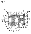
- gear drive unit 10 consists of a first unit 12, in which a spindle 16 is mounted with a drive wheel 18 arranged thereon in a support tube 14.
- the carrier tube 14 is produced, for example, by deep drawing and has an end region 20 on a cup-shaped bearing receptacle 22 for the drive wheel 18.
- the spindle 16 protrudes through an opening 24 in the pot-shaped bearing receptacle 22 out of the support tube 14 and is connected for example via a threaded nut, not shown, to the body.
- the other spindle end 26 is located within the support tube 14 and is axially and radially supported by a bearing plate 28 which is secured within the support tube 14.
- the spindle end 26 has, for example, a spherical contact surface 30, which rests axially in cup-shaped bearing plate 28.
- a thrust washer 32 with increased strength can be arranged in the end shield 28.
- the drive wheel 18 is formed in the embodiment as a worm wheel 19, which has axial extensions 34 for the radial bearing.
- the drive wheel 18 is for example made of plastic directly sprayed onto the spindle 16 and has a toothing 36 which meshes with an output element 40 of a drive unit 42.
- the drive unit 42 is designed as an electric motor 43 and is connected by means of a coupling device 44 with the first assembly 12.
- the carrier tube 14 has for positioning relative to the coupling device 44 on a formation 46, in which a corresponding fixing element 48 of the coupling device 44 engages.
- the support tube 14 has a radial recess 50 into which the output member 40 engages.
- the output element 40 is designed, for example, as a worm 39, which is arranged on an armature shaft 41 of the electric motor 43.
- the support tube 14, which practically forms a housing for the separate assembly 12, further comprises a receptacle 52, in which a fastening device 54 - for example, a hinge pin 55 - is inserted. With this fastening device 54, the support tube 14 is pivotally connected to a part to be adjusted 58 in the motor vehicle, such as a non-illustrated seat or a seat part, which is adjusted relative to another seat part.
- a first support member 62 is formed as an outer ring 64 which abuts in an outer peripheral surface 66 of the support tube 14.
- a further support member 62 is formed as a circular disc 68, which rests against the inner wall 70 of the support tube 14.
- the support members 62 are connected, for example by means of welds 72 to the support tube 14.
- the lower half shows an attachment of the support member 62 by means of a caulking 74 by plastic material deformation.
- a tensile force 80 acts on the spindle 16 in the event of a rear-end collision in the axial direction 76, the spindle 16 is supported via the drive wheel 18 in the cup-shaped bearing receptacle 22 of the carrier tube 14.
- the tensile force 80 is transmitted via the support tube 14 to the fastening device 54, whereby a high material load occurs between the receptacle 52 and the end 60 of the support tube 14.
- These increased forces are absorbed by one or more support members 62, which thus increase the nondestructive power consumption of the support tube 14.
- the spindle end 26 and thus the part 58 to be adjusted remains in its intended location even in the event of a crash.
- FIG. 2 and FIG. 3 show a further embodiment of a spindle drive 10, in which the support elements 62 have a thread 78, which with a corresponding Counter thread 79 of the support tube 14 cooperate.
- the support elements 62 are inserted in the axial direction 76 on or into the support tube 14 until the attachment device 54 is supported on the support elements 62 in the axial direction of the support tube 14.
- FIG. 3 (along III-III of the FIG. 2 ) it can be seen that on the support tube 14, both an external thread 79 and an internal thread 79 is formed, to which the support members 62 are simply screwed or screwed.
- the support member 62 which bears against the inner wall 70 is formed as an inner ring 65, which is for example also penetrated by a submersible spindle 16.
- the force 80 is introduced via the threads 78, 79 over the entire circumference of the support tube 14 on this, whereby a partial increase in voltage in the region of the receptacle 52 is avoided, and the previously unloaded areas of the support tube 14 be shared.
- the support elements 62 have self-tapping threads 78, which form when screwed into the support tube 14 in this mating thread 79.
- the fastening device 54 is in this example axially on the bearing plate 28, so that also acting on the spindle 16 compressive forces are absorbed via the fastening bolt 54.
- the bearing plate 28 has in this embodiment over its entire axial length 29 has a constant outer diameter, whereby its mechanical stability is increased.
- the recess 50 is rectangular in the support tube 14, so that the worm 39 can mesh with the drive wheel 18.
- FIGS. 2 and 3 only the separate assembly 12 is shown, which can be mounted completely independent of the drive unit 42.
- the coupling device 44 which fixes the drive unit 42 in relation to the carrier tube 14 for torque transmission, is subsequently connected to the preassembled assembly 12 via the molding 46.
- the assembly of the support members 62 may be made, for example, at the end of assembly of the separate assembly 12, or only after the complete assembly of the transmission drive unit 10. If the support member 62 formed as an outer ring 64, this can be mounted in advance on the support tube 14, before the spindle 16 is inserted into the support tube 14.
- FIG. 4 a further embodiment is shown in which the support members 62 are formed as clamping discs 81.
- the support elements 62 are in this case formed as a circular disk 68, which at a radially outer edge region 83 in the axial direction of the support tube 14 of the Point away fastening device 54.
- the support members 62 are plate-shaped, with a planar central portion 86 and the angled outer edge portion 83.
- the support member 62 has an edge 84 which is buried in the assembled state in the inner wall 70 of the support tube 14.
- the notch 84 may in this case for example have an angle of 90 °, or sharp-edged, for example, be formed with a ridge.
- a power transmission disc 88 is arranged, which is made more stable than the support members 62.
- the power transmission disc 88 has a greater thickness 94, or is made of a stronger material.
- the power transmission disc 88 is in this case, for example, not radially attached to the support tube 14, but loosely inserted into the support tube 14. During the axial mounting of the clamping disks 81, these are pressed against the power transmission disk 88 and these in turn against the fastening device 54. Thus, the central planar portion 86 of the clamping disks 81 is supported on the fastening device 54, wherein the bias voltage is predetermined by means of the pressing force of the clamping disks 81.
- a spindle nut 90 is arranged, which is connected to a part 58 to be adjusted, for example, a motor vehicle seat.
- a pulling force 80 acts on the spindle 16 via the part 58 to be adjusted, as a result of which high forces occur between the carrier tube 14 and the fastening device 54.
- the force 98 acting on the fastening bolt 55 is transmitted uniformly over the circumference 82 of the supporting elements 62 to the end 60 of the support tube 14.
- the support tube 14 in Different methods are produced and have different concrete formations.
- the support tube 14 may be formed as a smooth cylinder tube, in which two separate end shields 28 are arranged for the storage of the spindle 16.
- the spindle 16 is preferably mounted on the drive wheel mounted thereon 18, but can be stored in a variation but also by means of bearing surfaces which are formed directly on the spindle 16.
- the invention is not limited to the use of a hinge pin 55 as a fastening device 54, but the support tube 14 may also have a different kind of receptacle 52 for attachment to the body / adjustment part 58.
- a dipping spindle 16 can be mounted in the support tube 14, in which case both cup-shaped bearing receivers 22 have an opening 24 through which the spindle 16 protrudes.
- the torque transmission is not limited to a worm gear 19, 39, but can for example be transmitted by means of a spur gear.
- the shape and material selection of the support members 62 is selected according to the strength requirement, with one or more support members 62 attached as needed.
- the cross section of the support tube 14 is not limited to a circle, however, in a cylindrical embodiment of the support tube 14, the support member 62 can be easily formed as a subsequent floor surface or wall reinforcement.
Abstract
Claims (18)
- Unité d'entraînement et de transmission (10), en particulier pour le déplacement d'une partie mobile (58) dans un véhicule automobile, comprenant un groupe motopropulseur (42) qui entraîne, par le biais d'un élément de prise de force (40), une roue motrice (18) montée sur une broche (16) de l'unité d'entraînement et de transmission (10), et la roue motrice (18) étant montée à rotation dans un tube porteur (14) de l'unité d'entraînement et de transmission (10) qui présente un logement (52) pour un dispositif de fixation (54) pour dévier les forces de collision, au moins un élément de support de forme circulaire ou annulaire (62) pouvant être monté séparément ultérieurement étant fixé entre une extrémité axiale (60) du tube porteur (14) et le logement (52), en vue de renforcer mécaniquement le tube porteur (14), l'élément de support (62) étant introduit axialement sur ou dans le tube porteur (14) jusqu'à ce que celui-ci s'applique axialement, au moins dans le cas de l'application d'une force extérieure, contre le dispositif de fixation (54) réalisé sous la forme d'un boulon de fixation (55).
- Unité d'entraînement et de transmission (10) selon la revendication 1, caractérisée en ce que l'élément de support (62) est réalisé sous la forme d'une bague extérieure (64), qui s'applique contre une surface périphérique extérieure (66) du tube porteur (14).
- Unité d'entraînement et de transmission (10) selon l'une quelconque des revendications 1 ou 2, caractérisée en ce que l'élément de support (62) est réalisé sous forme de bague intérieure (65) ou sous forme de disque circulaire (68), lesquels s'appliquent contre une surface de paroi interne (70) du tube porteur (14).
- Unité d'entraînement et de transmission (10) selon l'une quelconque des revendications précédentes, caractérisée en ce que l'élément de support (62) peut être connecté au tube porteur (14) au moyen d'un filetage (78), notamment autotaraudeur.
- Unité d'entraînement et de transmission (10) selon l'une quelconque des revendications précédentes, caractérisée en ce que l'élément de support (62) peut être connecté au tube porteur (14) par soudage, collage ou déformation plastique de matériau.
- Unité d'entraînement et de transmission (10) selon l'une quelconque des revendications précédentes, caractérisée en ce que le matériau de l'élément de support (62) - de préférence de l'acier trempé - présente une plus grande tenue que le matériau du tube porteur (14), qui est notamment fabriqué en tant que pièce métallique emboutie.
- Unité d'entraînement et de transmission (10) selon l'une quelconque des revendications précédentes, caractérisée en ce que le logement (52) est réalisé sous forme d'alésage de passage radial dans le tube porteur (14), dans lequel alésage peut être enfoncé le boulon de fixation (55) en tant qu'élément de fixation (54), lequel boulon de fixation peut à son tour être fixé à la carrosserie ou à la partie à déplacer (58).
- Unité d'entraînement et de transmission (10) selon l'une quelconque des revendications précédentes, caractérisée en ce que l'élément de fixation (54, 55) s'applique dans la direction axiale du tube porteur (14) contre l'élément de support (62) après son montage.
- Unité d'entraînement et de transmission (10) selon l'une quelconque des revendications précédentes, caractérisée en ce que la roue motrice (18) est supportée au moyen d'au moins une plaque formant palier (28) avec un logement de palier (22) en forme de pot radialement et axialement dans le tube porteur (14), la plaque formant palier (28) étant fabriquée de préférence en plastique.
- Unité d'entraînement et de transmission (10) selon l'une quelconque des revendications précédentes, caractérisée en ce que le groupe motopropulseur (42) est connecté au moyen d'un dispositif d'accouplement (44) au tube porteur (14), lequel présente, pour l'engagement de l'élément de prise de force (40) dans la roue motrice (18), un évidement radial (50).
- Unité d'entraînement et de transmission (10) selon l'une quelconque des revendications précédentes, caractérisée en ce que l'élément de support (62) est serré fixement au tube porteur (14) de manière serrée contre le dispositif de fixation (54).
- Unité d'entraînement et de transmission (10) selon l'une quelconque des revendications précédentes, caractérisée en ce que l'élément de support (62) est réalisé sous forme de disque de serrage (81), qui s'enfonce sur toute sa périphérie (82) avec une arête (84) dans la surface de paroi intérieure (70) du tube porteur (14).
- Unité d'entraînement et de transmission (10) selon l'une quelconque des revendications précédentes, caractérisée en ce que le disque de serrage (81) présente une région de bord extérieure (83) qui est tournée à l'écart du dispositif de fixation (54) dans la direction axiale du tube porteur (14), le disque de serrage (81) étant notamment fabriqué sous forme de pièce estampée-cintrée (96).
- Unité d'entraînement et de transmission (10) selon l'une quelconque des revendications précédentes, caractérisée en ce que plusieurs éléments de support identiques (62, 81) sont fixés au tube porteur (14) en s'appliquant axialement les uns contre les autres.
- Unité d'entraînement et de transmission (10) selon l'une quelconque des revendications précédentes, caractérisée en ce qu'entre l'au moins un élément de support (62) et le dispositif de fixation (54) est disposé un disque de transfert de force (88), qui transfère les forces (98) agissant depuis le dispositif de fixation (54) sur l'au moins un élément de support (62).
- Procédé de fabrication d'une unité d'entraînement et de transmission (10) selon l'une quelconque des revendications précédentes, caractérisé en ce que la broche (16) est d'abord montée avec la roue motrice (18) et l'élément de support (62) sur le tube porteur (14) en tant qu'unité constructive séparée (12), puis le groupe motopropulseur (42) est fixé au tube porteur (14) au moyen du dispositif d'accouplement (44).
- Procédé selon la revendication 16, caractérisé en ce que pour différentes exigences de solidité d'une unité d'entraînement et de transmission (10), on utilise toujours un tube porteur standard unitaire (14), sur lequel sont fixés des éléments de support (62) de stabilité différente en fonction de ses sollicitations.
- Procédé selon la revendication 16, caractérisé en ce qu'après le montage des moyens de fixation sur le tube porteur (14), l'élément de support (62) ou un nombre différent d'éléments de support identiques (62) d'un système modulaire sont enfoncés dans le tube porteur (14) et sont pressés avec précontrainte contre l'élément de fixation (54), l'élément de support (62) étant fixé de manière autonome au moyen de griffes de fixation dans le tube porteur (14) pour empêcher un déplacement dans le sens inverse à la direction d'enfoncement (85).
Applications Claiming Priority (2)
| Application Number | Priority Date | Filing Date | Title |
|---|---|---|---|
| DE102005046357A DE102005046357A1 (de) | 2005-09-28 | 2005-09-28 | Getriebe-Antriebseinheit, insbesondere zum Verstellen eines beweglichen Teils im Kraftfahrzeug, mit einem Trägerrohr |
| PCT/EP2006/063617 WO2007036371A1 (fr) | 2005-09-28 | 2006-06-28 | Unite de transmission et d'entrainement presentant un tuyau support et procede de production d'une telle unite |
Publications (2)
| Publication Number | Publication Date |
|---|---|
| EP1931532A1 EP1931532A1 (fr) | 2008-06-18 |
| EP1931532B1 true EP1931532B1 (fr) | 2012-03-07 |
Family
ID=36940729
Family Applications (1)
| Application Number | Title | Priority Date | Filing Date |
|---|---|---|---|
| EP06763915A Expired - Fee Related EP1931532B1 (fr) | 2005-09-28 | 2006-06-28 | Unite de transmission et d'entrainement presentant un tuyau support et procede de production d'une telle unite |
Country Status (7)
| Country | Link |
|---|---|
| US (1) | US20080196965A1 (fr) |
| EP (1) | EP1931532B1 (fr) |
| JP (1) | JP2009510347A (fr) |
| KR (1) | KR101060149B1 (fr) |
| CN (1) | CN101272929B (fr) |
| DE (1) | DE102005046357A1 (fr) |
| WO (1) | WO2007036371A1 (fr) |
Families Citing this family (14)
| Publication number | Priority date | Publication date | Assignee | Title |
|---|---|---|---|---|
| DE102007059558A1 (de) | 2007-12-11 | 2009-06-18 | Robert Bosch Gmbh | Gewindespindel-Verstellantrieb |
| DE102008009474A1 (de) * | 2008-02-15 | 2009-08-20 | Robert Bosch Gmbh | Getriebe-Antriebseinheit mit einer Lageranordnung |
| DE102010018952B4 (de) * | 2010-04-28 | 2013-03-14 | Keiper Gmbh & Co. Kg | Beschlag für einen Fahrzeugsitz, Fahrzeugsitz und Verfahren zum Zusammenbau eines Beschlags |
| DE102012207129A1 (de) * | 2012-04-27 | 2013-10-31 | Robert Bosch Gmbh | Getriebespindel sowie Spindelgetriebe, sowie Verfahren zum Herstellen einer Getriebespindel |
| JP5634437B2 (ja) * | 2012-05-23 | 2014-12-03 | 株式会社ミツバ | リニアアクチュエータ |
| DE102012211062A1 (de) * | 2012-06-27 | 2014-01-02 | Stabilus Gmbh | Antriebseinrichtung und Baukasten für eine derartige Antriebseinrichtung |
| DE102012219629A1 (de) * | 2012-10-26 | 2014-04-30 | Robert Bosch Gmbh | Drehspindelantrieb |
| DE102014201742A1 (de) | 2014-01-31 | 2015-08-06 | Johnson Controls Metals and Mechanisms GmbH & Co. KG | Stellantrieb für ein kraftfahrzeug, insbesondere für einen kraftfahrzeugsitz |
| DE102014219412B4 (de) * | 2014-09-25 | 2021-04-01 | Autoliv Development Ab | Gurtschlosseinrichtung für einen Sicherheitsgurt |
| DE102014226584A1 (de) * | 2014-12-19 | 2016-07-07 | Robert Bosch Gmbh | Anordnung für einen Stellgeberantrieb in einem Kraftfahrzeug sowie einen Stellgeberantrieb, sowie Herstellungsverfahren eines solchen |
| US10081245B2 (en) * | 2016-06-24 | 2018-09-25 | GM Global Technology Operations LLC | Cradle to body joint release mechanism |
| EP3296593B1 (fr) * | 2016-09-15 | 2023-06-14 | Ratier-Figeac SAS | Actionneur à vis pour une gouverne de vol et méthode de surveillance de son fonctionnement |
| JP6704827B2 (ja) * | 2016-09-30 | 2020-06-03 | 日本電産サンキョー株式会社 | 直線駆動装置 |
| DE102016219104A1 (de) * | 2016-09-30 | 2018-04-05 | Brose Fahrzeugteile Gmbh & Co. Kg, Coburg | Verstellvorrichtung einer Lordosenstütze oder eines Seitenwangenverstellers mit Spindelantrieb für ein Sitzelement eines Fahrzeugsitzes |
Family Cites Families (13)
| Publication number | Priority date | Publication date | Assignee | Title |
|---|---|---|---|---|
| US3339892A (en) * | 1966-06-03 | 1967-09-05 | Duff Norton Co | Jack mechanism |
| US3409272A (en) * | 1967-02-13 | 1968-11-05 | Rasmussen Reed | Camper support including lift means |
| US3798983A (en) * | 1972-05-15 | 1974-03-26 | W Smith | Adaptable gear housing for linear actuator construction |
| US3792619A (en) * | 1972-08-31 | 1974-02-19 | R Cannon | Constant tension ball screw feed design |
| JPH02296543A (ja) * | 1989-05-12 | 1990-12-07 | Nissan Motor Co Ltd | シートスライド装置 |
| US4923175A (en) * | 1989-05-19 | 1990-05-08 | Kysor Industrial Corporation | Constant mesh gear box landing gear |
| JPH0732249Y2 (ja) * | 1990-05-29 | 1995-07-26 | 池田物産株式会社 | パワーシートスライド装置 |
| DE4101470C1 (en) * | 1991-01-19 | 1992-06-25 | Keiper Recaro Gmbh & Co, 5630 Remscheid, De | Car seat adjuster with threaded spindle - on whose oen end is fitted connector, with nut housing coupled to adjustable seat part |
| US5435523A (en) * | 1994-10-25 | 1995-07-25 | Wesbar Corporation | Trailer tongue jack |
| DE29513272U1 (de) * | 1995-08-18 | 1997-01-02 | Bosch Gmbh Robert | Vorrichtung zum Verstellen eines Sitzes in einem Kraftfahrzeug |
| EP1223073B1 (fr) * | 2000-12-19 | 2008-12-31 | Robert Bosch Gmbh | Unité transmission-entraînement pour le réglage d'un siège ou une direction assistée, avec au moins un élément de support |
| WO2004028305A1 (fr) * | 2002-09-16 | 2004-04-08 | Dewert Antriebs- Und Systemtechnik Gmbh & Co. Kg | Entrainement de meuble par moteur electrique |
| DE102004042457A1 (de) * | 2004-08-31 | 2006-03-16 | Robert Bosch Gmbh | Getriebe-Antriebseinheit |
-
2005
- 2005-09-28 DE DE102005046357A patent/DE102005046357A1/de not_active Withdrawn
-
2006
- 2006-06-28 US US11/994,591 patent/US20080196965A1/en not_active Abandoned
- 2006-06-28 WO PCT/EP2006/063617 patent/WO2007036371A1/fr active Application Filing
- 2006-06-28 KR KR1020087007643A patent/KR101060149B1/ko not_active IP Right Cessation
- 2006-06-28 EP EP06763915A patent/EP1931532B1/fr not_active Expired - Fee Related
- 2006-06-28 CN CN2006800359003A patent/CN101272929B/zh not_active Expired - Fee Related
- 2006-06-28 JP JP2008532689A patent/JP2009510347A/ja not_active Ceased
Also Published As
| Publication number | Publication date |
|---|---|
| WO2007036371A1 (fr) | 2007-04-05 |
| US20080196965A1 (en) | 2008-08-21 |
| CN101272929B (zh) | 2010-09-29 |
| EP1931532A1 (fr) | 2008-06-18 |
| KR20080046214A (ko) | 2008-05-26 |
| DE102005046357A1 (de) | 2007-03-29 |
| JP2009510347A (ja) | 2009-03-12 |
| KR101060149B1 (ko) | 2011-08-29 |
| CN101272929A (zh) | 2008-09-24 |
Similar Documents
| Publication | Publication Date | Title |
|---|---|---|
| EP1931532B1 (fr) | Unite de transmission et d'entrainement presentant un tuyau support et procede de production d'une telle unite | |
| EP1931534B1 (fr) | Unite de transmission et d'entrainement munie d'un module de reception, servant notamment a deplacer une partie mobile d'automobile | |
| EP1931895B1 (fr) | Unite de transmission et d'entrainement a fixation de palier sans jeu axial, utilisee notamment pour deplacer une partie mobile dans une automobile | |
| EP1987270B1 (fr) | Mécanisme d'entrainement à broche, notamment pour positionner une pièce mobile dans un véhicule automobile et procédé de fabrication de ce mécanisme d'entrainement à broche | |
| EP1797353B1 (fr) | Procede de fabrication d'une transmission et transmission ainsi fabriquee | |
| WO2018019609A1 (fr) | Dispositif d'entraînement pour un système d'entraînement de confort d'un véhicule à moteur et système d'entraînement de confort | |
| WO2011051017A1 (fr) | Unité de transmission par engrenage | |
| DE102012007329B4 (de) | Welle-Nabe-Verbindung | |
| WO2005103519A1 (fr) | Ensemble de transfert de force a bague d'arret ondulee | |
| DE102007062363A1 (de) | Schaltgetriebe | |
| EP2029388B1 (fr) | Dispositif de réglage d'un composant d'un véhicule à moteur, comprenant un carter de frein et procédé de production et/ou de montage d'un dispositif de réglage | |
| DE102004058963A1 (de) | Zahnriemenscheibe | |
| EP1579125B1 (fr) | Unite d'entrainement de transmission | |
| DE10114453A1 (de) | Getriebe-Antriebseinheit mit Axialspielausgleich | |
| DE102006020174A1 (de) | Getriebeeinheit mit einem Trägerrohr | |
| EP2423036A1 (fr) | Mécanisme oscillant | |
| EP2090806B1 (fr) | Unité d'entrainement de transmission avec un ensemble de roulement | |
| DE102016223357A1 (de) | Abtriebsschnittstelle für einen Getriebemotorantrieb | |
| DE102011114296A1 (de) | Elektromechanische Lenkung | |
| EP2659152A1 (fr) | Dispositif de palier pour une unité d'entraînement, et entraînement de réglage présentant un dispositif de palier | |
| DE102006041076A1 (de) | Getriebeanordnung mit axialer Sicherung | |
| DE3516313A1 (de) | Elastisches lagerelement fuer antriebsaggregate in kraftfahrzeugen | |
| DE19908888B4 (de) | Verstellbarer Rückblickspiegel, insbesondere Außenspiegel für ein Kraftfahrzeug | |
| DE102019130423A1 (de) | Antriebsstrang | |
| DE102017205220A1 (de) | Elektrische Maschine mit einer axialen Abstützung der Ankerwelle |
Legal Events
| Date | Code | Title | Description |
|---|---|---|---|
| PUAI | Public reference made under article 153(3) epc to a published international application that has entered the european phase |
Free format text: ORIGINAL CODE: 0009012 |
|
| 17P | Request for examination filed |
Effective date: 20080428 |
|
| AK | Designated contracting states |
Kind code of ref document: A1 Designated state(s): DE FR HU IT |
|
| DAX | Request for extension of the european patent (deleted) | ||
| RBV | Designated contracting states (corrected) |
Designated state(s): DE FR HU IT |
|
| 17Q | First examination report despatched |
Effective date: 20100208 |
|
| GRAP | Despatch of communication of intention to grant a patent |
Free format text: ORIGINAL CODE: EPIDOSNIGR1 |
|
| GRAS | Grant fee paid |
Free format text: ORIGINAL CODE: EPIDOSNIGR3 |
|
| GRAA | (expected) grant |
Free format text: ORIGINAL CODE: 0009210 |
|
| AK | Designated contracting states |
Kind code of ref document: B1 Designated state(s): DE FR HU IT |
|
| REG | Reference to a national code |
Ref country code: DE Ref legal event code: R096 Ref document number: 502006011085 Country of ref document: DE Effective date: 20120426 |
|
| PGFP | Annual fee paid to national office [announced via postgrant information from national office to epo] |
Ref country code: IT Payment date: 20120623 Year of fee payment: 7 |
|
| PLBE | No opposition filed within time limit |
Free format text: ORIGINAL CODE: 0009261 |
|
| STAA | Information on the status of an ep patent application or granted ep patent |
Free format text: STATUS: NO OPPOSITION FILED WITHIN TIME LIMIT |
|
| 26N | No opposition filed |
Effective date: 20121210 |
|
| REG | Reference to a national code |
Ref country code: DE Ref legal event code: R097 Ref document number: 502006011085 Country of ref document: DE Effective date: 20121210 |
|
| PG25 | Lapsed in a contracting state [announced via postgrant information from national office to epo] |
Ref country code: IT Free format text: LAPSE BECAUSE OF NON-PAYMENT OF DUE FEES Effective date: 20130628 |
|
| PG25 | Lapsed in a contracting state [announced via postgrant information from national office to epo] |
Ref country code: HU Free format text: LAPSE BECAUSE OF FAILURE TO SUBMIT A TRANSLATION OF THE DESCRIPTION OR TO PAY THE FEE WITHIN THE PRESCRIBED TIME-LIMIT Effective date: 20060628 |
|
| REG | Reference to a national code |
Ref country code: DE Ref legal event code: R084 Ref document number: 502006011085 Country of ref document: DE |
|
| REG | Reference to a national code |
Ref country code: DE Ref legal event code: R084 Ref document number: 502006011085 Country of ref document: DE Effective date: 20150506 |
|
| REG | Reference to a national code |
Ref country code: FR Ref legal event code: PLFP Year of fee payment: 11 |
|
| REG | Reference to a national code |
Ref country code: FR Ref legal event code: PLFP Year of fee payment: 12 |
|
| PGFP | Annual fee paid to national office [announced via postgrant information from national office to epo] |
Ref country code: FR Payment date: 20170621 Year of fee payment: 12 |
|
| PGFP | Annual fee paid to national office [announced via postgrant information from national office to epo] |
Ref country code: DE Payment date: 20180807 Year of fee payment: 13 |
|
| PG25 | Lapsed in a contracting state [announced via postgrant information from national office to epo] |
Ref country code: FR Free format text: LAPSE BECAUSE OF NON-PAYMENT OF DUE FEES Effective date: 20180630 |
|
| REG | Reference to a national code |
Ref country code: DE Ref legal event code: R119 Ref document number: 502006011085 Country of ref document: DE |
|
| PG25 | Lapsed in a contracting state [announced via postgrant information from national office to epo] |
Ref country code: DE Free format text: LAPSE BECAUSE OF NON-PAYMENT OF DUE FEES Effective date: 20200101 |