EP1931455B1 - Cartridge having variable volume reservoirs - Google Patents
Cartridge having variable volume reservoirs Download PDFInfo
- Publication number
- EP1931455B1 EP1931455B1 EP06800634.5A EP06800634A EP1931455B1 EP 1931455 B1 EP1931455 B1 EP 1931455B1 EP 06800634 A EP06800634 A EP 06800634A EP 1931455 B1 EP1931455 B1 EP 1931455B1
- Authority
- EP
- European Patent Office
- Prior art keywords
- channel
- cartridge
- component
- variable volume
- transport
- Prior art date
- Legal status (The legal status is an assumption and is not a legal conclusion. Google has not performed a legal analysis and makes no representation as to the accuracy of the status listed.)
- Not-in-force
Links
Images


Classifications
-
- B—PERFORMING OPERATIONS; TRANSPORTING
- B01—PHYSICAL OR CHEMICAL PROCESSES OR APPARATUS IN GENERAL
- B01L—CHEMICAL OR PHYSICAL LABORATORY APPARATUS FOR GENERAL USE
- B01L3/00—Containers or dishes for laboratory use, e.g. laboratory glassware; Droppers
- B01L3/50—Containers for the purpose of retaining a material to be analysed, e.g. test tubes
- B01L3/502—Containers for the purpose of retaining a material to be analysed, e.g. test tubes with fluid transport, e.g. in multi-compartment structures
- B01L3/5027—Containers for the purpose of retaining a material to be analysed, e.g. test tubes with fluid transport, e.g. in multi-compartment structures by integrated microfluidic structures, i.e. dimensions of channels and chambers are such that surface tension forces are important, e.g. lab-on-a-chip
- B01L3/502738—Containers for the purpose of retaining a material to be analysed, e.g. test tubes with fluid transport, e.g. in multi-compartment structures by integrated microfluidic structures, i.e. dimensions of channels and chambers are such that surface tension forces are important, e.g. lab-on-a-chip characterised by integrated valves
-
- B—PERFORMING OPERATIONS; TRANSPORTING
- B01—PHYSICAL OR CHEMICAL PROCESSES OR APPARATUS IN GENERAL
- B01F—MIXING, e.g. DISSOLVING, EMULSIFYING OR DISPERSING
- B01F31/00—Mixers with shaking, oscillating, or vibrating mechanisms
- B01F31/65—Mixers with shaking, oscillating, or vibrating mechanisms the materials to be mixed being directly submitted to a pulsating movement, e.g. by means of an oscillating piston or air column
-
- B—PERFORMING OPERATIONS; TRANSPORTING
- B01—PHYSICAL OR CHEMICAL PROCESSES OR APPARATUS IN GENERAL
- B01F—MIXING, e.g. DISSOLVING, EMULSIFYING OR DISPERSING
- B01F33/00—Other mixers; Mixing plants; Combinations of mixers
- B01F33/30—Micromixers
-
- B—PERFORMING OPERATIONS; TRANSPORTING
- B01—PHYSICAL OR CHEMICAL PROCESSES OR APPARATUS IN GENERAL
- B01L—CHEMICAL OR PHYSICAL LABORATORY APPARATUS FOR GENERAL USE
- B01L3/00—Containers or dishes for laboratory use, e.g. laboratory glassware; Droppers
- B01L3/50—Containers for the purpose of retaining a material to be analysed, e.g. test tubes
- B01L3/502—Containers for the purpose of retaining a material to be analysed, e.g. test tubes with fluid transport, e.g. in multi-compartment structures
- B01L3/5027—Containers for the purpose of retaining a material to be analysed, e.g. test tubes with fluid transport, e.g. in multi-compartment structures by integrated microfluidic structures, i.e. dimensions of channels and chambers are such that surface tension forces are important, e.g. lab-on-a-chip
- B01L3/502723—Containers for the purpose of retaining a material to be analysed, e.g. test tubes with fluid transport, e.g. in multi-compartment structures by integrated microfluidic structures, i.e. dimensions of channels and chambers are such that surface tension forces are important, e.g. lab-on-a-chip characterised by venting arrangements
-
- B—PERFORMING OPERATIONS; TRANSPORTING
- B01—PHYSICAL OR CHEMICAL PROCESSES OR APPARATUS IN GENERAL
- B01L—CHEMICAL OR PHYSICAL LABORATORY APPARATUS FOR GENERAL USE
- B01L2200/00—Solutions for specific problems relating to chemical or physical laboratory apparatus
- B01L2200/06—Fluid handling related problems
- B01L2200/0621—Control of the sequence of chambers filled or emptied
-
- B—PERFORMING OPERATIONS; TRANSPORTING
- B01—PHYSICAL OR CHEMICAL PROCESSES OR APPARATUS IN GENERAL
- B01L—CHEMICAL OR PHYSICAL LABORATORY APPARATUS FOR GENERAL USE
- B01L2200/00—Solutions for specific problems relating to chemical or physical laboratory apparatus
- B01L2200/06—Fluid handling related problems
- B01L2200/0684—Venting, avoiding backpressure, avoid gas bubbles
-
- B—PERFORMING OPERATIONS; TRANSPORTING
- B01—PHYSICAL OR CHEMICAL PROCESSES OR APPARATUS IN GENERAL
- B01L—CHEMICAL OR PHYSICAL LABORATORY APPARATUS FOR GENERAL USE
- B01L2200/00—Solutions for specific problems relating to chemical or physical laboratory apparatus
- B01L2200/06—Fluid handling related problems
- B01L2200/0689—Sealing
-
- B—PERFORMING OPERATIONS; TRANSPORTING
- B01—PHYSICAL OR CHEMICAL PROCESSES OR APPARATUS IN GENERAL
- B01L—CHEMICAL OR PHYSICAL LABORATORY APPARATUS FOR GENERAL USE
- B01L2200/00—Solutions for specific problems relating to chemical or physical laboratory apparatus
- B01L2200/10—Integrating sample preparation and analysis in single entity, e.g. lab-on-a-chip concept
-
- B—PERFORMING OPERATIONS; TRANSPORTING
- B01—PHYSICAL OR CHEMICAL PROCESSES OR APPARATUS IN GENERAL
- B01L—CHEMICAL OR PHYSICAL LABORATORY APPARATUS FOR GENERAL USE
- B01L2200/00—Solutions for specific problems relating to chemical or physical laboratory apparatus
- B01L2200/16—Reagents, handling or storing thereof
-
- B—PERFORMING OPERATIONS; TRANSPORTING
- B01—PHYSICAL OR CHEMICAL PROCESSES OR APPARATUS IN GENERAL
- B01L—CHEMICAL OR PHYSICAL LABORATORY APPARATUS FOR GENERAL USE
- B01L2300/00—Additional constructional details
- B01L2300/06—Auxiliary integrated devices, integrated components
- B01L2300/0627—Sensor or part of a sensor is integrated
- B01L2300/0636—Integrated biosensor, microarrays
-
- B—PERFORMING OPERATIONS; TRANSPORTING
- B01—PHYSICAL OR CHEMICAL PROCESSES OR APPARATUS IN GENERAL
- B01L—CHEMICAL OR PHYSICAL LABORATORY APPARATUS FOR GENERAL USE
- B01L2300/00—Additional constructional details
- B01L2300/06—Auxiliary integrated devices, integrated components
- B01L2300/0627—Sensor or part of a sensor is integrated
- B01L2300/0645—Electrodes
-
- B—PERFORMING OPERATIONS; TRANSPORTING
- B01—PHYSICAL OR CHEMICAL PROCESSES OR APPARATUS IN GENERAL
- B01L—CHEMICAL OR PHYSICAL LABORATORY APPARATUS FOR GENERAL USE
- B01L2300/00—Additional constructional details
- B01L2300/08—Geometry, shape and general structure
- B01L2300/0861—Configuration of multiple channels and/or chambers in a single devices
- B01L2300/087—Multiple sequential chambers
-
- B—PERFORMING OPERATIONS; TRANSPORTING
- B01—PHYSICAL OR CHEMICAL PROCESSES OR APPARATUS IN GENERAL
- B01L—CHEMICAL OR PHYSICAL LABORATORY APPARATUS FOR GENERAL USE
- B01L2300/00—Additional constructional details
- B01L2300/12—Specific details about materials
- B01L2300/123—Flexible; Elastomeric
-
- B—PERFORMING OPERATIONS; TRANSPORTING
- B01—PHYSICAL OR CHEMICAL PROCESSES OR APPARATUS IN GENERAL
- B01L—CHEMICAL OR PHYSICAL LABORATORY APPARATUS FOR GENERAL USE
- B01L2400/00—Moving or stopping fluids
- B01L2400/04—Moving fluids with specific forces or mechanical means
- B01L2400/0475—Moving fluids with specific forces or mechanical means specific mechanical means and fluid pressure
- B01L2400/0481—Moving fluids with specific forces or mechanical means specific mechanical means and fluid pressure squeezing of channels or chambers
-
- B—PERFORMING OPERATIONS; TRANSPORTING
- B01—PHYSICAL OR CHEMICAL PROCESSES OR APPARATUS IN GENERAL
- B01L—CHEMICAL OR PHYSICAL LABORATORY APPARATUS FOR GENERAL USE
- B01L2400/00—Moving or stopping fluids
- B01L2400/04—Moving fluids with specific forces or mechanical means
- B01L2400/0475—Moving fluids with specific forces or mechanical means specific mechanical means and fluid pressure
- B01L2400/0487—Moving fluids with specific forces or mechanical means specific mechanical means and fluid pressure fluid pressure, pneumatics
-
- B—PERFORMING OPERATIONS; TRANSPORTING
- B01—PHYSICAL OR CHEMICAL PROCESSES OR APPARATUS IN GENERAL
- B01L—CHEMICAL OR PHYSICAL LABORATORY APPARATUS FOR GENERAL USE
- B01L2400/00—Moving or stopping fluids
- B01L2400/06—Valves, specific forms thereof
- B01L2400/0633—Valves, specific forms thereof with moving parts
- B01L2400/0655—Valves, specific forms thereof with moving parts pinch valves
Definitions
- a variety of assays have been developed to detect the presence and/or amount of biological or chemical agents in a sample.
- the desire for assays that can be performed in the field has increased the demand for smaller and more efficient assay equipment. This demand has been met with equipment that employs one or more sensors held within a cartridge.
- the cartridge can generally be extracted from or inserted into- an assay system at the location where the assay is performed.
- WO2004061085 discloses methods and apparatus for implementing microfluidic analysis through the use of a monolithic elastomer membrane associated with an integrated pneumatic manifold.
- the invention is defined by the features of claim 1.
- variable volume reservoirs can also be employed to control the volume of a solution that is transported into a chamber.
- the cartridge can include a plurality of variable volume reservoirs that are each in liquid communication with one another and with a plurality of chambers in the cartridge.
- the cartridge can also include one or more valves arranged such that closing a portion of the valves closes the liquid communication between a first one of the variable volume reservoirs and the other variable volume reservoirs while permitting liquid communication between the first variable volume reservoir and a first one of the chambers.
- variable volume reservoirs can be employed in conjunction with a vent channel.
- the cartridge can include a vent channel that intersects a transport channel such that the vent channel carries gasses from the transport channel.
- the vent channel can be in fluid communication with a variable volume reservoir. Accordingly, the vent channel can transport the gasses from the transport channel to the variable volume reservoir.
- the cartridge can also include one or more vent channels where a fluid is vented from a transport channel through which a solution is transported.
- the vent channel can be in liquid communication with a variable volume reservoir.
- the variable volume reservoir can expand as the pressure in the vent channel increases as a result of additional fluids entering the vent channel. Accordingly, the fluids are vented into the variable volume reservoir.
- the cartridge allows for internal storage of the gasses and other fluids vented from the channels where the solutions are transported.
- the storage component 12 includes one or more reservoirs 14 configured to store solutions that are use in conjunction with an assay.
- the storage component can include a medium positioned so as to retain a solution in one or more of the reservoirs. In some instances, the medium is positioned so as to seal one or more of the reservoirs.
- FIG. 2 is a schematic diagram illustrating the interior of the transport component 13.
- the transport component 13 includes one or more product chambers 26.
- the product chamber 26 can be empty and serve as a storage chamber. Additionally or alternately, the product chamber can include components for processing of the product.
- the product chamber can include a porous material for filtration, a catalyst, a reactant for reacting with product, a culture medium or media for culturing, reagents for amplification and/or a coating for anchoring chemical or biological agents in the chamber.
- one or more of the product chambers includes one or more sensors (not shown).
- a suitable sensor includes, but is not limited to, an electrochemical sensor. Examples of an electrochemical sensor are taught in U.S. patent application Ser. No.
- the transport component 13 includes a plurality of transport channels through which the solutions flow.
- the cartridge includes a plurality of inlet channels for transporting a solution to the mixing component 27.
- the mixing component 27 can be used to mix different solutions so as to form a product solution that is transported to one or more of the product chambers.
- the inlet channels include input channels 28 configured to transport fluid from a disruption mechanism 16, and a first common channel 29 configured to transport solution from an input channel 28 to the mixing component 27.
- the transport component also includes outlet channels that transport the solution from the mixing component to the product chambers. Examples of outlet channels include a plurality of independent channels 30 configured to transport a solution to a product chamber and a second common channel 32 configured to transport solutions from the mixing component 27 to the independent channels 30.
- the transport component 13 includes a plurality of vent channels 34.
- the vent channels interface with one of the transport channels such that the vent channel transports gasses from the transport channels.
- the vent channels illustrated in Figure 2 interface with the input channels such that air is vented from the input channel.
- the vent channels interface with the input channels at a valve.
- the vent channels 34 are configured to vent air from the valve while allowing solution to flow through the valve.
- a vent channel can be configured to vent air from an input channel while a solution is transported along the input channel and into the valve.
- the vent channels are in fluid communication with a vent relief device 35 where the gasses carried by the vent channel are stored and/or released to the atmosphere.
- An inlet valve 41 is positioned along the first common channel 29 and an outlet valve 42 is positioned along the second common channel 32.
- the transport component optionally includes one or more volume control devices 44 positioned along the second common channel 32.
- a volume control device 44 can be employed to control the volume of a liquid that is transported to a product chamber. As will become evident below, a volume control device 44 can include variable volume reservoir.
- solutions are transported from the reservoirs 14 ( Figure 1A ) into the mixing component.
- the solutions are mixed in the mixing chamber to provide a product solution.
- the product solution is then transported into each of the product chambers 26 in a desired volume.
- the first valve 38 labeled V 1 , the inlet valve 41, and the associated vent relief device 35 can be opened to vent air during solution delivery, and the outlet valve 42 closed after venting, and the pressure on a solution contained within a reservoir ( Figure 1A ) disrupted by the disruption mechanism 16 labeled P 1 can be increased.
- the solution flows through a first portion of the input channel 28, through the first valve 38 labeled V 1 , into a second portion of the input channel, into the first common channel 29 and into the mixing component 27.
- the first valve 38 labeled V 1 is closed, the first valve 38 labeled V 2 is opened, and the pressure on a second solution contained within a reservoir ( Figure 1A ) disrupted by the disruption mechanism 16 labeled P 2 can be increased.
- the second solution flows through a first portion of the input channel 28, through the first valve 38 labeled V 2 , into a second portion of the input channel, into the first common channel 29 and into the mixing component 27.
- the transport component includes an inlet valve 41
- the inlet valve and/or each of the first valves 38 can be closed and the mixing component operated as to mix the solutions so as to form a product solution.
- each of the first valves 38 can be closed and the mixing component operated as to mix the solutions so as to form a product solution.
- Figure 3A through Figure 3C illustrate a suitable construction for a storage component 12.
- Figure 3A is a perspective view of the storage component 12.
- Figure 3B is a cross section of the storage component 12 shown in Figure 3A taken along a line extending between the brackets labeled B in Figure 3A .
- Figure 3C is a perspective view of the storage component 12 before assembly of the cartridge.
- the storage component 12 includes a cover 46, a base 48 and a sealing medium 50.
- the cover 46 includes a plurality of pockets 52 extending from a common platform 54.
- the cover 46 is coupled with the base 48 such that the pockets 52 each define a portion of a reservoir 14 and the base 48 defines another portion of the reservoir 14.
- a plurality of openings 53 each extend through the base 48 and are positioned so as to provide an opening into a reservoir 14.
- Figure 3D through Figure 3E illustrates a transport component suitable for use with the storage component illustrated in Figure 3A through Figure 3C .
- Figure 3D is a perspective view of a portion of the transport component.
- a plurality of piercing mechanisms 56 extend from a side of the transport component.
- the piercing mechanisms 56 serve as disruption mechanisms that can disrupt the sealing integrity of the sealing medium.
- Figure 3E is a cross section of a cartridge employing the storage component of Figure 3A and the transport component of Figure 3D . The cross section is taken through piercing mechanism 56.
- the piercing mechanisms 56 are positioned on the transport component so as to be aligned with the pockets in the storage component. Upon coupling of the storage component 12 and the transport component 13, the piercing mechanisms 56 pierce the portion of the sealing medium 50 that seals the reservoirs. Piercing of the sealing medium 50 allows the solution in a reservoir to flow into contact with a piercing mechanism 56.
- a lumen 57 extends through one or more of the piercing mechanisms 16 and into the transport component 13. Accordingly, the lumen 57 can transport a solution from a reservoir into the transport component 13.
- the piercing mechanisms 56 are positioned on the transport component 13 so as to be aligned with the openings 53 in the base 48 of the storage component 12.
- the base 48 can be constructed of a material that cannot be pierced by a piercing mechanism 56. Accordingly, the piercing mechanisms pierce the portion of the sealing medium extending across the openings. As a result, the base 48 limits the location of disruptions created by a piercing mechanism 56 to a localized region of the sealing medium 50.
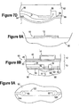
- Figure 4A through Figure 4D illustrate a cartridge employing a different embodiment of a disruption mechanism 16.
- Figure 4A is a cross section of a storage component 12 taken along the line labeled B in Figure 3A .
- the storage component 12 includes a cover 46, a base 48 and a sealing medium 50.
- Figure 4B is a bottom-view of the storage component 12 shown in Figure 4A without the sealing medium 50 in place.
- Figure 4C is a perspective view of a portion of the transport component having the disruption mechanism.
- Figure 4D is a cross section of a cartridge employing the disruption mechanism 16 illustrated on the transport component 13 of Figure 4C .
- An opening 53 extends through the base 48 of the storage component 12 so as to provide fluid pathway from a reservoir 14.
- the base 48 includes a recess 58 extending into the bottom of the base 48 and surrounding the opening 53.
- the sealing medium 50 extends across the recess 58 and the opening 53 and accordingly seals the opening 53 as evident in Figure 4A .
- a ridge 59 extending from a side of the transport component shown in Figure 4C defines a cup on the side of the transport component 13.
- the cup serves as a disrupting mechanism 16.
- the cup pushes a portion of the sealing medium 50 into the recess 58 as shown in Figure 4D .
- the pushing motion stretches the sealing medium 50.
- the sealing medium 50 can include one or more channels that open upon stretching but that are closed without stretching.
- the one or more channels are positioned over the opening 53 and/or over the recess 58. As a result, the solution in a reservoir 14 can flow from the reservoir 14 through the one or more channels into contact with the disruption mechanism 16.
- the one or more channels opened by a cup each serve as a disruption in the sealing integrity of the sealing medium.
- An opening 61 extends from the bottom of the cup into the transport component 13.
- Suitable sealing media for use with the cups includes, but is not limited to, thermoplastic elastomers (TPEs).
- the recess 58 is illustrated as surrounding the opening 53 and spaced apart from the opening such that a lip 63 is formed around the opening 53, the recess 58 need not be spaced apart from the opening.
- the recess 58 can transition directly into the opening 53 such that the lip 63 is not present.
- the disruption mechanism can be structured as a cup, as a blunted piercing mechanism or as a combination of the two.
- pockets serve as the reservoirs in the storage component
- the pockets can be deformable when an external pressure is applied.
- an operator can apply pressure to a pocket to drive a solution from within the reservoir and into the transport component 13.
- pressure applied to the pockets can be employed to transport solution from a reservoir into the transport component.
- a material for the cover 46 of the storage component 12 such as PVC or polyurethane allows a pocket 52 to be deformed by application of a pressure to the pocket 52.
- the base 60 includes a plurality of sensors 70 for detecting the presence and/or amount of an agent in a solution.
- the sensors 70 are positioned on the base 60 such that each sensor is positioned in a product chamber upon assembly of the transport component.
- the illustrated sensors include a working electrode 72, a reference electrode 74 and a counter electrode 76.
- each of the electrodes is formed from a single layer of an electrically conductive material. Suitable electrically conductive materials, include, but are not limited to, gold.
- Electrical leads 78 provide electrical communication between each of the electrodes and an electrical contact 80.
- Other sensor constructions are disclosed in U.S. patent application Ser. No. 09/848727, filed on May 5, 2001 , entitled "Biological Identification System with Integrated Sensor Chip".
- a plurality of reservoir openings 83 extend through the base 60. As will become evident below, the reservoir openings serve as an opening through which a liquid in a channel can enter and/or exit a variable volume reservoir.
- the mixing component includes a plurality of the variable volume reservoirs. Additionally, volume control devices can each include a variable volume reservoir.
- first valve channels 84 and second valve channels 85 extend through the base 60.
- each first valve channel 84 is associated with a second valve channel 85 in that the first valve channel 84 and associated second valve channel 85 are part of the same valve.
- the first valve channels 84 serve as valve inlets and the second valve channels 84 serve as valve outlets.
- first valve channels 84 for the first valves are aligned with an input channel 28 such that a solution flowing through an input channel can flow into the first valve channel and the associated second valve channels 85 are aligned with the first common channel such that a solution in the second valve channel can flow into the first common channel.
- the first valve channels 84 for the second valves are aligned with the second common channel such that a solution flowing through the second common channel can flow into the first valve channel and the associated second valve channels are aligned with an independent channel such that a solution in the second valve channel can flow into the independent channel.
- the first valve channels 84 for the inlet valve, the outlet valve, and the isolation valve are aligned with a portion of the second common channel such that a solution flowing through a portion of the second common channel can flow into the first valve channel and the associated second valve channels are aligned with an independent channel such that a solution in the second valve channel can flow into another portion of the second common channel.
- the transport component 13 is configured such that air can flow through the vent channels 34 while restricting solution flow through the vent channel 34.
- the vent channels 34 are sized to allow airflow through the vent channel 34 while preventing or reducing the flow of solution through the vent channel 34.
- a vent channel 34 includes one or more constriction regions 89.
- the constriction region 89 can include a plurality of ducts, conduits, channels or pores through an obstruction in the vent channel.
- the ducts, conduits, channels or pores can each be sized to permit air flow while obstructing solution flow.
- Figure 5E is bottom view of the portion of a cover 62 having a vent channel 34 with a constriction region 89.
- Figure 5F is a cross section of the constriction region 89 taken at the line labeled F.
- the constriction region 89 includes a plurality of ducts 91 that are each sized to permit airflow while restricting or obstructing solution flow.
- the cover 62 illustrated in Figure 5A includes a plurality of waste outlet structures 93 extending from the common platform 66. These outlet structures align with the waste channels 36 upon assembly of the transport component and provide an outlet for waste solution from a product chamber.
- the outlet structures can be a piercing mechanism that pierces an empty reservoir 14 on the storage component upon assembly of the cartridge. In these instances, the waste solution flows into the reservoir 14 during operation of the cartridge. Alternately, the outlet structures can be accessible above the cartridge. For instance, the outlet structures can extend through or around the storage component. In these instances, the outlet structures can be connected to a tube or other device that carries the waste solution away from the cartridge. The outlet structures need not be present on the storage device.
- the transport component can include an internal reservoir into which the waste solutions can flow.
- the base 60 and the cover 62 can define a waste reservoir into which the waste channels 36 flow.
- FIG. 6A through Figure 6E illustrate one of the valves formed upon assembly of the transport component shown in Figure 5A and Figure 5B .
- Figure 6A is a topview of the portion of the transport component that includes the valve.
- the dashed lines illustrate items that are positioned in the interior of the transport component.
- Figure 6B is a bottom view of the portion of the transport component shown in Figure 6A .
- the dashed lines in Figure 6B illustrate the location of a valve region 91 where the flexible layer 64 is not attached to the base 60.
- Figure 6C is a cross section of the cartridge shown in Figure 6A taken along a line extending between the brackets labeled C.
- Figure 6D is a cross section of the cartridge shown in Figure 6A taken along a line extending between the brackets labeled D.
- a first valve channel 84 in the base 60 is aligned with an input channel 88 in the cover 62 such that a solution in the input channel can flow into the first valve channel. Accordingly, the first valve channel 84 defines a portion of the input channel.
- a second valve channel 85 in the base 60 is aligned with an output channel 89 in the cover 62 such that a solution in the second valve channel can flow into the output channel.
- the base 60 and the cover 62 act together to form an obstruction 92 between the input channel 88 and the output channel 89.
- the cover provides a second obstruction between the input channel and the vent channel.
- the flexible material is positioned over the obstruction 92, the first valve channel and the second valve channel. As a result, the flexible material is positioned over a portion of the input channel and a portion of the output channel. Further, the flexible material is positioned over a portion of the vent channel.
- the displacement between the flexible layer 64 and the obstruction 92 changes. For instance, as the valve opens from a closed position or as the valve opens further, the flexible layer 64 moves away from the obstruction 92 as shown in Figure 6E . The movement of the flexible layer 64 away from the obstruction 92 increases the volume of a fluid path around the obstruction 92. Once the upstream pressure on the solution passes a threshold pressure or the flexible membrane is pulled down by an external force, the solution begins to flow through the fluid path around the obstruction 92 as illustrated by the arrow labeled F in Figure 6E . Accordingly, the movement of the flexible layer away from the obstruction allows the solution to flow from the input channel 88 into the output channel 89.
- the flexible layer 64 moves away from the obstruction 92 as shown in Figure 7D .
- the movement of the flexible layer 64 away from the obstruction 92 creates a fluid path around the obstruction 92.
- the solution begins to flow through the fluid path around the obstruction 92 as illustrated by the arrow labeled D in Figure 7D . Accordingly, the movement of the flexible layer away from the obstruction allows the solution to flow from the input channel 88 into the output channel 89.
- One or more of the channels that intersect at the valve can have a volume that decreases as the channel approaches the valve.
- the portion of a channel opposite the flexible material can slope toward the flexible material as the channel approaches the valve as is evident in Figure 7C .
- the portion of the input channel 88 that ends at the valve can have a height that tapers in a direction approaching the valve.
- the height of a channel is the height of the channel at a point along the channel being measured in a direction perpendicular to the flexible material and extending from the flexible material across the channel to the point of the opposing side located furthest from the flexible material.
- the slope reduces the nearly perpendicular corner that can be formed between the side and bottom of an input channel 88 at location where the channel ends at the valve.
- a sharp corner can serve as a pocket where air can be caught.
- the slope can help to smooth the corner and can accordingly reduce formation of air bubbles in these pockets.
- Figure 7A through Figure 7D also show the height of the vent channel 90 tapering toward the valve. This taper can prevent the formation of air pockets in the vent channel 90.
- Figure 7A through Figure 7D show tapers in the height of the input channel 88 and the vent channel 90, the valve can be constructed such that neither the input channel 88 nor the vent channel 90 includes a taper; such that the input channel 88 includes the taper and the vent channel 90 excludes the taper; or such that the vent channel 90 includes the taper and the input channel 88 excludes the taper.
- the portion of the vent channel 90 closest to the input channel 88 at the valve can be parallel to the adjacent portion input channel 88 as is evident in Figure 7A .
- the length of the parallel portion can optionally be about the same as the width of the adjacent portion of the input channel 88. This construction can reduce the formation of air bubbles in the valve.
- the arrangement of the input channel 88, the output channel 89 and the vent channel 90 relative to one another can be changed from the arrangement illustrated in Figure 6A through Figure 7D .
- the portion of the output channel and the input channel 88 at the intersection of the channel can both be parallel to the output channel as illustrated by the valve labeled V in Figure 2 .
- Figure 2 illustrates the valve positioned part way along the input channel, the valve can be constructed so the valve is positioned at an intersection of the input channel, vent channel and common channel.
- the flexibility in channel arrangement can increase the number of features that can be placed on a single cartridge.
- the above valves can be opened by increasing the upstream pressure on the solution enough to deform the flexible layer 64 and/or by employing an external mechanism to move the flexible layer 64 away from the obstruction 92.
- the upstream pressure can be increased by compressing the reservoir 14 that contains a solution in fluid communication with the input channel.
- An example of a suitable external mechanism is a vacuum. The vacuum can be employed to pull the flexible layer 64 away from the obstruction 92.
- the transport component can be constructed such that the flexible layer 64 is spaced apart from the obstruction 92 when the positive pressure is not applied to the upstream solution.
- a gap between the flexible layer 64 and the obstruction 92 can be sufficiently small that the surface tension of the solution prevents the solution from flowing past the obstruction 92 until a threshold pressure is reached. In these instances, the movement of the flexible layer 64 away from the obstruction 92 serves to increase the volume of the path around the obstruction 92.
- The,relative size of the inlet valve channel 84 and the outlet valve channel 85 can also play a role in valve performance. For instance, a ratio of the cross-sectional area of the outlet valve channel 85 to cross-sectional area of the inlet valve channel 84 can affect valve performance. Back flow through the valve can be reduced when this ratio is less than one. Additionally, reducing the ratio serves to reduce the backflow.
- the input channel and/or the outlet channel has more than one flow path.
- the outlet flow channel can include a plurality of holes through the base. In these instances, the cross sectional area of the outlet channel is the sum of the total cross sectional area of each of the flow paths.
- the amount of vacuum pulled at a port 98 can be sufficient to completely or partially open the valve aligned with that port as illustrated by the dashed line and the arrow labeled A in Figure 8B .
- the manifold 96 can be employed to selectively open the valves on the cartridge.
- the manifold can be configured to generate a positive pressure on a port. The positive pressure can keep a valve closed during operation of the cartridge. For instance, the manifold can be operated so as to keep the outlet valve closed while a solution is flowed into the mixing component.
- a manifold 96 is disclosed in Figure 8A and Figure 8B , a cartridge constructed as disclosed above may operate without the use of an external mechanism for opening and closing of the valves. As a result, the manifold 96 is optional.
- Figure 9A through Figure 9D illustrate a mixing component formed upon assembly of the transport component shown in Figure 5A and Figure 5B .
- Figure 9A is a top-view of the portion of the transport component that includes the mixing component.
- Figure 9B is a bottom view of the portion of the transport component shown in Figure 9A .
- Figure 9C is a cross section of the cartridge shown in Figure 9B taken along a line extending between the brackets labeled C.
- Figure 9D is a cross section of the cartridge shown in Figure 9B taken along a line extending between the brackets labeled D.
- the transport component is treated as transparent in Figure 9A . Accordingly, the solid lines in Figure 9A illustrate features that are included on the cover 62 but that are located in the interior of the transport component.
- dashed lines in Figure 9A illustrate items that are positioned in the interior of the transport component on the base 60.
- the component is again treated as transparent in Figure 9B .
- the solid lines show the features that are included on the cover 62 and on the base 60 in the interior of the transport component.
- the mixing component includes a plurality of variable volume reservoirs.
- the dashed lines in Figure 9B illustrate the perimeter of the variable volume reservoirs 100 where the flexible layer 64 is not attached to the base 60.
- the brackets labeled F in Figure 9C and Figure 9D indicate the locations where the flexible layer 64 is not attached to the base 60 and accordingly illustrate the location of the variable volume reservoirs.
- the variable volume reservoirs illustrated in Figure 9A through Figure 9D are illustrated with a zero volume.
- Figure 9E illustrates the mixing component of Figure 9D where each of the variable volume reservoirs contains a solution. Accordingly, each of the variable volume reservoirs contains a non-zero volume.
- the mixing component includes two variable volume reservoirs 100.
- a mixing channel 102 provides liquid communication between the variable volume reservoirs 100.
- the mixing channel 102 can have a cross-sectional area that is larger than the cross sectional area of the inlet channel 104 and/or the outlet channel 106.
- a reservoir opening 83 extends through base 60 and is positioned in the mixing channel 102. Accordingly, the reservoir opening 83 serves as a conduit through which solution can enter the variable volume reservoir 100 from the mixing channel 102 and/or enter the mixing channel from the variable volume reservoir.
- multiple mechanisms are available for increasing and decreasing the volume of a variable volume reservoir.
- Figure 9F through Figure 9K illustrate a method of operating the mixing component so as to mix solutions.
- Figure 9F is a cross section of the mixing component.
- the inlet valve 41 and the outlet valve 42 are also illustrated in Figure 9F .
- the inlet valve 41 and the outlet valve 42 are shown as being separate from the mixing component, the inlet valve 41 and/or the outlet valve 42 can be incorporated into the mixing component.
- the outlet valve 42 is closed and the inlet valve is opened as shown in Figure 9G .
- a first solution is transported through the inlet valve 41 and into the mixing component as illustrated by the arrows labeled A.
- the variable volume reservoirs can be operated so the first solution flows into both of the variable volume reservoirs or so the first solution flows into one of the variable volume reservoirs.
- the illustrated method shows the variable volume reservoirs operated so the first solution flows one of the variable volume reservoirs and accordingly increases the volume of the variable volume reservoir as illustrated by the arrow labeled B.
- a second solution is transported through the inlet valve 41 and into the mixing component.
- the interface between the first solution and the second solution is illustrated by the line labeled I in Figure 9G .
- the desired volume of the second solution is transported into the mixing component. Additional solutions can optionally be transported into the mixing component.
- the various solutions combine to form a product solution in the mixing component.
- the inlet valve is closed as shown in Figure 9H .
- the closure of the inlet valve 41 and the outlet valve 42 as shown in Figure 9H helps isolate the solutions in the mixing component from other regions of the cartridge during the mixing process.
- the above steps can be reversed to transport at least a portion of the product solution back into the first variable volume reservoir as shown in Figure 9J .
- the volume of the first variable volume reservoir 100A can be increased as shown by the arrow labeled A in Figure 9I .
- the volume of the volume of the second variable volume reservoir 100B can be decreased as shown by the arrow labeled B in Figure 9J .
- the result of these actions is transport of at least a portion of the product solution from the second variable volume reservoir 100B into the first variable volume reservoir 100A.
- the transport of the product solution back and forth between the variable volume reservoirs causes the solutions to be mixed.
- the quality of the mixing increases as the number of cycles increases.
- the product solution is preferably transported into one of the variable volume reservoirs at least 1 times, 10 times, or 100 times. Accordingly, the product solution is cycled between the variable volume reservoirs until the desired degree of mixing is achieved. Once the desired degree of mixing is achieved, the outlet valve is opened and the volume of the variable volume reservoirs is decreased. The decrease in volume transports the product solution out of the mixing component as shown by the arrow labeled A in Figure 9K .
- the inlet valve reduces backflow of the solutions through the inlet channels toward the storage reservoirs in the storage component.
- this function can also be achieved with the first valves.
- the inlet valve is optional.
- the illustrated mixing component optionally has the advantage that it can be bypassed.
- each of the variable volume reservoirs can be in the closed position while a solution is transported through the mixing component. As a result, the solution flows through the mixing component without flowing into the variable volume reservoirs.
- the positive pressure can be sufficient to decrease the volume of a variable volume reservoir and/or to keep a variable volume reservoir closed.
- the port 98 can include a mechanical device 110 for manipulating the flexible layer 64 as shown in Figure 9M .
- the device 110 can push on the flexible layer 64 toward the base 60 such that the volume of the variable volume reservoirs is decreased and/or pull the flexible layer 64 away from the base 60 such that the volume of the variable volume reservoirs is increased.
- Suitable mechanical devices include, but are not limited to, magnetic actuators, electrical actuators and pneumatic actuators.
- variable volume reservoir When an external device such as a manifold is employed to change the volume of a variable volume reservoir, a variety of mechanisms can be employed to transport the solution into the variable volume reservoir. For instance, the volume of a variable volume reservoir can be increased while the solution is in a transport channel in liquid communication with the variable volume reservoir. The increasing volume of the variable volume reservoir will draw the solution into the variable volume reservoir. Alternately, the volume of the variable volume reservoir can be increased before the solution is in a transport channel in liquid communication with the variable volume reservoir. The solution can then flow into the open variable volume reservoir.
- the outlet valve 42 and the isolation valve 43 are opened and a solution is transported into the variable volume reservoirs as illustrated by the arrow labeled A in Figure 10E .
- the second valves (40 in Figure 2 ) are closed to reduce or prevent flow of the solution into the independent channels (30 in Figure 2 ) and/or product chambers (26 in Figure 2 ).
- the isolation valve 43 is closed as shown in Figure 10F . Closing the isolation valve 43 closes the liquid communication between the volume control device 44 labeled VC 1 and the volume control device 44 labeled VC 2 .
- the outlet valve 42 is also closed to prevent backflow of the solution from the volume control device toward the mixing component.
- the second valves (40 in Figure 2 ) are opened either together or one after another. Opening the second valves (40 in Figure 2 ) opens the liquid communication between each of the product chambers (26 in Figure 2 ) and the associated variable volume reservoir 100. As a result, closing the isolation valve 43 and the outlet valve 42 while opening the second valves closes the liquid communication between the volume control devices while opening liquid communication between each of the product chambers and the associated volume control device. Further, this arrangement also closes the liquid communication between each of the volume control devices and at least one of the product chambers. For instance, this arrangement stops the liquid communication between the volume control device 44 labeled VC 1 and the product chamber labeled SC 2 in Figure 2 .
- volume of a volume control device 100 can be decreased an amount that is known to transport the desired amount of solution to the product chamber.
- the variable volume reservoir can be opened to a volume that is known to transport the desired amount of solution to the product chamber when the variable volume reservoir is closed. As a result, closing the variable volume reservoir 100 after it receives the solution will transport the desired volume of the solution to the product chamber.
- variable volume reservoirs may be reduced different volumes in order to transport the solution to a product chamber. Additionally or alternately, different variable volume reservoirs can be opened to different volumes before or while the solution is being transported into the variable volume reservoir.
- the function of the outlet valve 42 in the above method can be achieved with other valves in the transport component.
- the outlet valve prevents or reduces backflow of the solution.
- this can be achieved with the inlet valve 41 and/or the first valves 38 shown in Figure 2 .
- an additional isolation valve can be positioned along the second common channel 32 to provide this function.
- the use of the outlet valve in the above method is optional.
- the above method can be adapted such that a solution is transported to only a portion of the product chambers or is transported to only one of the product chambers.
- the above method can be performed without opening the variable chamber reservoir in the volume control device labeled VC 1 .
- the above method can be performed without opening the isolation valve 43.
- the volume control function provided by the volume control devices can be bypassed by operating the volume control devices with each of the variable volume reservoirs in the closed position. As a result, a solution will not flow into the variable volume reservoirs and the volume control function will be bypassed.
- Figure 11A illustrates the vent device (35 Figure 2 ) that is formed upon assembly of the transport component shown in Figure 5A and Figure 5B .
- Figure 11A is a cross section of the transport component.
- the vent device includes a first vent opening 86 in the base 60 aligned with a second vent opening 87 in the flexible layer 62.
- the first vent opening 86 and the second vent opening 87 are aligned with the vent channel 34.
- air in the vent channel 34 can flow through the first vent opening 86 and the second vent opening 87 into the atmosphere or into a containment device.
Landscapes
- Chemical & Material Sciences (AREA)
- Chemical Kinetics & Catalysis (AREA)
- Health & Medical Sciences (AREA)
- Dispersion Chemistry (AREA)
- Analytical Chemistry (AREA)
- General Health & Medical Sciences (AREA)
- Hematology (AREA)
- Clinical Laboratory Science (AREA)
- Automatic Analysis And Handling Materials Therefor (AREA)
- Containers And Packaging Bodies Having A Special Means To Remove Contents (AREA)
Applications Claiming Priority (2)
| Application Number | Priority Date | Filing Date | Title |
|---|---|---|---|
| US11/219,516 US7938573B2 (en) | 2005-09-02 | 2005-09-02 | Cartridge having variable volume reservoirs |
| PCT/US2006/029992 WO2007030236A2 (en) | 2005-09-02 | 2006-07-31 | Cartridge having variable volume reservoirs |
Publications (3)
| Publication Number | Publication Date |
|---|---|
| EP1931455A2 EP1931455A2 (en) | 2008-06-18 |
| EP1931455A4 EP1931455A4 (en) | 2012-06-06 |
| EP1931455B1 true EP1931455B1 (en) | 2014-09-03 |
Family
ID=37830204
Family Applications (1)
| Application Number | Title | Priority Date | Filing Date |
|---|---|---|---|
| EP06800634.5A Not-in-force EP1931455B1 (en) | 2005-09-02 | 2006-07-31 | Cartridge having variable volume reservoirs |
Country Status (7)
| Country | Link |
|---|---|
| US (2) | US7938573B2 (ja) |
| EP (1) | EP1931455B1 (ja) |
| JP (1) | JP2009507221A (ja) |
| CN (1) | CN101267878A (ja) |
| AU (1) | AU2006287825B2 (ja) |
| CA (1) | CA2618164C (ja) |
| WO (1) | WO2007030236A2 (ja) |
Families Citing this family (19)
| Publication number | Priority date | Publication date | Assignee | Title |
|---|---|---|---|---|
| US7938573B2 (en) * | 2005-09-02 | 2011-05-10 | Genefluidics, Inc. | Cartridge having variable volume reservoirs |
| KR101155763B1 (ko) | 2006-11-21 | 2012-06-12 | 메디메이트 홀딩 비.브이. | 유체용 이온 센서 및 그의 제조 방법 |
| WO2008141659A1 (en) * | 2007-05-18 | 2008-11-27 | Medimate Holding B.V. | Test chip with plug for measuring the concentration of an analyte in a liquid, housing for test chip and socket for plug |
| US8448499B2 (en) | 2008-12-23 | 2013-05-28 | C A Casyso Ag | Cartridge device for a measuring system for measuring viscoelastic characteristics of a sample liquid, a corresponding measuring system, and a corresponding method |
| US9174182B2 (en) | 2009-04-23 | 2015-11-03 | Koninklijke Philips N.V. | Mixer with zero dead volume and method for mixing |
| JP5456904B2 (ja) * | 2009-10-21 | 2014-04-02 | バイオカルティス、ソシエテ、アノニム | 平行空気圧インターフェース・プレートを備えたミクロ流体カートリッジ |
| WO2011062738A1 (en) | 2009-11-23 | 2011-05-26 | Mikhail Briman | Controlled electrochemical activation of carbon-based electrodes |
| WO2011090801A1 (en) * | 2010-01-23 | 2011-07-28 | Genefluidics, Inc. | Modular cartridge for liquid transport |
| JP5833755B2 (ja) | 2011-07-25 | 2015-12-16 | ブリマン、ミカイル | 診断試験用カートリッジ |
| CN104053992B (zh) * | 2012-01-16 | 2016-12-14 | 皇家飞利浦有限公司 | 确定包括细胞的体液中的靶分子的存在 |
| WO2014018167A2 (en) * | 2012-07-27 | 2014-01-30 | Genefluidics, Inc. | Cartridge for liquid transport |
| JP2017503175A (ja) * | 2013-12-31 | 2017-01-26 | キヤノン ユー.エス. ライフ サイエンシズ, インコーポレイテッドCanon U.S. Life Sciences, Inc. | 現場配置可能な小型フォーマットの迅速一次結果マイクロ流体システム |
| JP6506907B2 (ja) * | 2014-02-10 | 2019-04-24 | 株式会社エンプラス | 液体取扱装置 |
| US10087546B2 (en) | 2014-10-24 | 2018-10-02 | International Business Machines Corporation | Prevent and remove organics from reservoir wells |
| WO2016122643A1 (en) | 2015-01-30 | 2016-08-04 | Hewlett-Packard Development Company, L.P. | Diagnostic chip |
| CN105973888B (zh) * | 2016-07-21 | 2018-09-18 | 西安良升生物科技有限公司 | 一种快速检测血液中缺血修饰白蛋白的试剂盒 |
| CN105973887B (zh) * | 2016-07-21 | 2018-09-18 | 西安良升生物科技有限公司 | 一种快速检测血液中缺血修饰白蛋白的芯片 |
| US10738342B2 (en) | 2018-08-30 | 2020-08-11 | Urinary Technologies, Inc. | System for microbial species detection, quantification and antibiotic susceptibility identification |
| FR3088430B1 (fr) | 2018-11-09 | 2023-12-08 | Commissariat Energie Atomique | Dispositif microfluidique de preparation d'echantillons offrant une grande repetabilite |
Family Cites Families (21)
| Publication number | Priority date | Publication date | Assignee | Title |
|---|---|---|---|---|
| US265442A (en) * | 1882-10-03 | Churn | ||
| US2152455A (en) * | 1938-10-28 | 1939-03-28 | George K Ballentine | Dishwashing machine |
| US2376221A (en) * | 1942-04-08 | 1945-05-15 | Hartford Empire Co | Method of and apparatus for degassing liquids |
| GB1583157A (en) * | 1976-05-07 | 1981-01-21 | Kenova Ab | Syringes |
| US4227548A (en) * | 1979-02-27 | 1980-10-14 | Botnick Irlin H | Multiple control valve for mixing fluids |
| US5077017A (en) * | 1987-11-05 | 1991-12-31 | Biotrack, Inc. | Integrated serial dilution and mixing cartridge |
| DE69117464T2 (de) * | 1990-09-18 | 1996-10-10 | Barry Farris | Kolbenlose Spritze |
| US5223219A (en) * | 1992-04-10 | 1993-06-29 | Biotrack, Inc. | Analytical cartridge and system for detecting analytes in liquid samples |
| US5856174A (en) * | 1995-06-29 | 1999-01-05 | Affymetrix, Inc. | Integrated nucleic acid diagnostic device |
| US5836750A (en) * | 1997-10-09 | 1998-11-17 | Honeywell Inc. | Electrostatically actuated mesopump having a plurality of elementary cells |
| US6062722A (en) * | 1997-10-21 | 2000-05-16 | Micron Communications, Inc. | Fluid mixing and withdrawing methods |
| EP1181529A4 (en) * | 1999-04-23 | 2002-07-03 | Surromed Inc | DISPOSABLE OPTICAL CARTRIDGE WITH WC |
| GB0028647D0 (en) * | 2000-11-24 | 2001-01-10 | Nextgen Sciences Ltd | Apparatus for chemical assays |
| US6613286B2 (en) * | 2000-12-21 | 2003-09-02 | Walter J. Braun, Sr. | Apparatus for testing liquid/reagent mixtures |
| US7318912B2 (en) * | 2001-06-07 | 2008-01-15 | Nanostream, Inc. | Microfluidic systems and methods for combining discrete fluid volumes |
| US6939032B2 (en) * | 2001-10-25 | 2005-09-06 | Erie Scientific Company | Cover slip mixing apparatus |
| TW590982B (en) * | 2002-09-27 | 2004-06-11 | Agnitio Science & Technology I | Micro-fluid driving device |
| EP2404676A1 (en) * | 2002-12-30 | 2012-01-11 | The Regents of the University of California | Microfluidic Control Structures |
| JP4208820B2 (ja) * | 2003-11-28 | 2009-01-14 | 株式会社東芝 | 核酸検出カセット |
| US7476360B2 (en) * | 2003-12-09 | 2009-01-13 | Genefluidics, Inc. | Cartridge for use with electrochemical sensor |
| US7938573B2 (en) * | 2005-09-02 | 2011-05-10 | Genefluidics, Inc. | Cartridge having variable volume reservoirs |
-
2005
- 2005-09-02 US US11/219,516 patent/US7938573B2/en active Active
-
2006
- 2006-07-31 WO PCT/US2006/029992 patent/WO2007030236A2/en active Application Filing
- 2006-07-31 AU AU2006287825A patent/AU2006287825B2/en not_active Ceased
- 2006-07-31 CA CA2618164A patent/CA2618164C/en not_active Expired - Fee Related
- 2006-07-31 JP JP2008529045A patent/JP2009507221A/ja active Pending
- 2006-07-31 CN CNA2006800322278A patent/CN101267878A/zh active Pending
- 2006-07-31 EP EP06800634.5A patent/EP1931455B1/en not_active Not-in-force
-
2011
- 2011-01-28 US US12/931,350 patent/US8333499B2/en active Active
Also Published As
| Publication number | Publication date |
|---|---|
| EP1931455A4 (en) | 2012-06-06 |
| CA2618164C (en) | 2014-01-21 |
| US7938573B2 (en) | 2011-05-10 |
| JP2009507221A (ja) | 2009-02-19 |
| US20070053796A1 (en) | 2007-03-08 |
| US8333499B2 (en) | 2012-12-18 |
| AU2006287825A1 (en) | 2007-03-15 |
| CN101267878A (zh) | 2008-09-17 |
| EP1931455A2 (en) | 2008-06-18 |
| US20110215101A1 (en) | 2011-09-08 |
| WO2007030236A3 (en) | 2007-11-29 |
| AU2006287825B2 (en) | 2011-04-14 |
| CA2618164A1 (en) | 2007-03-15 |
| WO2007030236A2 (en) | 2007-03-15 |
Similar Documents
| Publication | Publication Date | Title |
|---|---|---|
| EP1931455B1 (en) | Cartridge having variable volume reservoirs | |
| EP1692261B1 (en) | Cartridge for use with electrochemical sensor | |
| CN109738632B (zh) | 多指标微流控芯片及其使用方法 | |
| US5290518A (en) | Flexible extraction device with burstable sidewall | |
| CN108443579B (zh) | 一种能控制液体流动的微阀及微流控芯片 | |
| US6431212B1 (en) | Valve for use in microfluidic structures | |
| US7357898B2 (en) | Microfluidics packages and methods of using same | |
| US20020148992A1 (en) | Pneumatic valve interface for use in microfluidic structures | |
| US20100104474A1 (en) | Micro fluidic device | |
| EP2025405B1 (en) | Metering assembly and method of dispensing fluid | |
| US8920749B2 (en) | Microchip and liquid sending method for microchip | |
| JP2003506679A (ja) | 気体の内部送達および減圧の適用のための流体相互接続、相互接続マニホルドおよび微小流体性デバイス | |
| CN110505918B (zh) | 用于形成乳状液阵列的系统、方法以及装置 | |
| US10260091B2 (en) | Analysis unit for performing a polymerase chain reaction, method for operating such an analysis unit, and method for producing such an analysis unit | |
| KR20050104348A (ko) | 유체 촉진 및 분석을 위한 마이크로유체식 장치 | |
| CN111530514B (zh) | 微流动气控芯片 | |
| CN117940216A (zh) | 微流体装置和用于运行微流体装置的方法 | |
| CN101166971A (zh) | 用于与电化学传感器一起使用的盒匣 | |
| JP2023051246A (ja) | 液体取扱装置および液体取扱システム | |
| JP2023545641A (ja) | 容積式ポンプを有するマイクロ流体デバイス |
Legal Events
| Date | Code | Title | Description |
|---|---|---|---|
| PUAI | Public reference made under article 153(3) epc to a published international application that has entered the european phase |
Free format text: ORIGINAL CODE: 0009012 |
|
| 17P | Request for examination filed |
Effective date: 20080228 |
|
| AK | Designated contracting states |
Kind code of ref document: A2 Designated state(s): AT BE BG CH CY CZ DE DK EE ES FI FR GB GR HU IE IS IT LI LT LU LV MC NL PL PT RO SE SI SK TR |
|
| AX | Request for extension of the european patent |
Extension state: AL BA HR MK RS |
|
| A4 | Supplementary search report drawn up and despatched |
Effective date: 20120508 |
|
| RIC1 | Information provided on ipc code assigned before grant |
Ipc: B01F 5/12 20060101AFI20120503BHEP |
|
| DAX | Request for extension of the european patent (deleted) | ||
| 17Q | First examination report despatched |
Effective date: 20130312 |
|
| REG | Reference to a national code |
Ref country code: DE Ref legal event code: R079 Ref document number: 602006042954 Country of ref document: DE Free format text: PREVIOUS MAIN CLASS: B01F0005120000 Ipc: B01F0011000000 |
|
| RIC1 | Information provided on ipc code assigned before grant |
Ipc: B01F 13/00 20060101ALI20140131BHEP Ipc: B01F 11/00 20060101AFI20140131BHEP Ipc: B01L 3/00 20060101ALI20140131BHEP |
|
| GRAP | Despatch of communication of intention to grant a patent |
Free format text: ORIGINAL CODE: EPIDOSNIGR1 |
|
| INTG | Intention to grant announced |
Effective date: 20140319 |
|
| RAP1 | Party data changed (applicant data changed or rights of an application transferred) |
Owner name: GENEFLUIDICS, INC. |
|
| GRAS | Grant fee paid |
Free format text: ORIGINAL CODE: EPIDOSNIGR3 |
|
| GRAA | (expected) grant |
Free format text: ORIGINAL CODE: 0009210 |
|
| AK | Designated contracting states |
Kind code of ref document: B1 Designated state(s): AT BE BG CH CY CZ DE DK EE ES FI FR GB GR HU IE IS IT LI LT LU LV MC NL PL PT RO SE SI SK TR |
|
| REG | Reference to a national code |
Ref country code: GB Ref legal event code: FG4D |
|
| REG | Reference to a national code |
Ref country code: AT Ref legal event code: REF Ref document number: 685266 Country of ref document: AT Kind code of ref document: T Effective date: 20140915 Ref country code: CH Ref legal event code: EP |
|
| REG | Reference to a national code |
Ref country code: IE Ref legal event code: FG4D |
|
| REG | Reference to a national code |
Ref country code: DE Ref legal event code: R096 Ref document number: 602006042954 Country of ref document: DE Effective date: 20141016 |
|
| REG | Reference to a national code |
Ref country code: AT Ref legal event code: MK05 Ref document number: 685266 Country of ref document: AT Kind code of ref document: T Effective date: 20140903 |
|
| PG25 | Lapsed in a contracting state [announced via postgrant information from national office to epo] |
Ref country code: ES Free format text: LAPSE BECAUSE OF FAILURE TO SUBMIT A TRANSLATION OF THE DESCRIPTION OR TO PAY THE FEE WITHIN THE PRESCRIBED TIME-LIMIT Effective date: 20140903 Ref country code: FI Free format text: LAPSE BECAUSE OF FAILURE TO SUBMIT A TRANSLATION OF THE DESCRIPTION OR TO PAY THE FEE WITHIN THE PRESCRIBED TIME-LIMIT Effective date: 20140903 Ref country code: SE Free format text: LAPSE BECAUSE OF FAILURE TO SUBMIT A TRANSLATION OF THE DESCRIPTION OR TO PAY THE FEE WITHIN THE PRESCRIBED TIME-LIMIT Effective date: 20140903 Ref country code: LT Free format text: LAPSE BECAUSE OF FAILURE TO SUBMIT A TRANSLATION OF THE DESCRIPTION OR TO PAY THE FEE WITHIN THE PRESCRIBED TIME-LIMIT Effective date: 20140903 Ref country code: GR Free format text: LAPSE BECAUSE OF FAILURE TO SUBMIT A TRANSLATION OF THE DESCRIPTION OR TO PAY THE FEE WITHIN THE PRESCRIBED TIME-LIMIT Effective date: 20141204 |
|
| REG | Reference to a national code |
Ref country code: NL Ref legal event code: VDEP Effective date: 20140903 |
|
| REG | Reference to a national code |
Ref country code: LT Ref legal event code: MG4D |
|
| PG25 | Lapsed in a contracting state [announced via postgrant information from national office to epo] |
Ref country code: CY Free format text: LAPSE BECAUSE OF FAILURE TO SUBMIT A TRANSLATION OF THE DESCRIPTION OR TO PAY THE FEE WITHIN THE PRESCRIBED TIME-LIMIT Effective date: 20140903 Ref country code: LV Free format text: LAPSE BECAUSE OF FAILURE TO SUBMIT A TRANSLATION OF THE DESCRIPTION OR TO PAY THE FEE WITHIN THE PRESCRIBED TIME-LIMIT Effective date: 20140903 Ref country code: AT Free format text: LAPSE BECAUSE OF FAILURE TO SUBMIT A TRANSLATION OF THE DESCRIPTION OR TO PAY THE FEE WITHIN THE PRESCRIBED TIME-LIMIT Effective date: 20140903 |
|
| PG25 | Lapsed in a contracting state [announced via postgrant information from national office to epo] |
Ref country code: NL Free format text: LAPSE BECAUSE OF FAILURE TO SUBMIT A TRANSLATION OF THE DESCRIPTION OR TO PAY THE FEE WITHIN THE PRESCRIBED TIME-LIMIT Effective date: 20140903 |
|
| PG25 | Lapsed in a contracting state [announced via postgrant information from national office to epo] |
Ref country code: EE Free format text: LAPSE BECAUSE OF FAILURE TO SUBMIT A TRANSLATION OF THE DESCRIPTION OR TO PAY THE FEE WITHIN THE PRESCRIBED TIME-LIMIT Effective date: 20140903 Ref country code: PT Free format text: LAPSE BECAUSE OF FAILURE TO SUBMIT A TRANSLATION OF THE DESCRIPTION OR TO PAY THE FEE WITHIN THE PRESCRIBED TIME-LIMIT Effective date: 20150105 Ref country code: CZ Free format text: LAPSE BECAUSE OF FAILURE TO SUBMIT A TRANSLATION OF THE DESCRIPTION OR TO PAY THE FEE WITHIN THE PRESCRIBED TIME-LIMIT Effective date: 20140903 Ref country code: IS Free format text: LAPSE BECAUSE OF FAILURE TO SUBMIT A TRANSLATION OF THE DESCRIPTION OR TO PAY THE FEE WITHIN THE PRESCRIBED TIME-LIMIT Effective date: 20150103 Ref country code: SK Free format text: LAPSE BECAUSE OF FAILURE TO SUBMIT A TRANSLATION OF THE DESCRIPTION OR TO PAY THE FEE WITHIN THE PRESCRIBED TIME-LIMIT Effective date: 20140903 Ref country code: RO Free format text: LAPSE BECAUSE OF FAILURE TO SUBMIT A TRANSLATION OF THE DESCRIPTION OR TO PAY THE FEE WITHIN THE PRESCRIBED TIME-LIMIT Effective date: 20140903 |
|
| PG25 | Lapsed in a contracting state [announced via postgrant information from national office to epo] |
Ref country code: PL Free format text: LAPSE BECAUSE OF FAILURE TO SUBMIT A TRANSLATION OF THE DESCRIPTION OR TO PAY THE FEE WITHIN THE PRESCRIBED TIME-LIMIT Effective date: 20140903 |
|
| REG | Reference to a national code |
Ref country code: DE Ref legal event code: R097 Ref document number: 602006042954 Country of ref document: DE |
|
| PLBE | No opposition filed within time limit |
Free format text: ORIGINAL CODE: 0009261 |
|
| STAA | Information on the status of an ep patent application or granted ep patent |
Free format text: STATUS: NO OPPOSITION FILED WITHIN TIME LIMIT |
|
| PG25 | Lapsed in a contracting state [announced via postgrant information from national office to epo] |
Ref country code: DK Free format text: LAPSE BECAUSE OF FAILURE TO SUBMIT A TRANSLATION OF THE DESCRIPTION OR TO PAY THE FEE WITHIN THE PRESCRIBED TIME-LIMIT Effective date: 20140903 |
|
| 26N | No opposition filed |
Effective date: 20150604 |
|
| PG25 | Lapsed in a contracting state [announced via postgrant information from national office to epo] |
Ref country code: IT Free format text: LAPSE BECAUSE OF FAILURE TO SUBMIT A TRANSLATION OF THE DESCRIPTION OR TO PAY THE FEE WITHIN THE PRESCRIBED TIME-LIMIT Effective date: 20140903 |
|
| PG25 | Lapsed in a contracting state [announced via postgrant information from national office to epo] |
Ref country code: SI Free format text: LAPSE BECAUSE OF FAILURE TO SUBMIT A TRANSLATION OF THE DESCRIPTION OR TO PAY THE FEE WITHIN THE PRESCRIBED TIME-LIMIT Effective date: 20140903 |
|
| PG25 | Lapsed in a contracting state [announced via postgrant information from national office to epo] |
Ref country code: MC Free format text: LAPSE BECAUSE OF FAILURE TO SUBMIT A TRANSLATION OF THE DESCRIPTION OR TO PAY THE FEE WITHIN THE PRESCRIBED TIME-LIMIT Effective date: 20140903 |
|
| REG | Reference to a national code |
Ref country code: CH Ref legal event code: PL |
|
| PG25 | Lapsed in a contracting state [announced via postgrant information from national office to epo] |
Ref country code: LU Free format text: LAPSE BECAUSE OF FAILURE TO SUBMIT A TRANSLATION OF THE DESCRIPTION OR TO PAY THE FEE WITHIN THE PRESCRIBED TIME-LIMIT Effective date: 20150731 |
|
| PG25 | Lapsed in a contracting state [announced via postgrant information from national office to epo] |
Ref country code: CH Free format text: LAPSE BECAUSE OF NON-PAYMENT OF DUE FEES Effective date: 20150731 Ref country code: LI Free format text: LAPSE BECAUSE OF NON-PAYMENT OF DUE FEES Effective date: 20150731 |
|
| REG | Reference to a national code |
Ref country code: IE Ref legal event code: MM4A |
|
| REG | Reference to a national code |
Ref country code: FR Ref legal event code: PLFP Year of fee payment: 11 |
|
| PG25 | Lapsed in a contracting state [announced via postgrant information from national office to epo] |
Ref country code: IE Free format text: LAPSE BECAUSE OF NON-PAYMENT OF DUE FEES Effective date: 20150731 Ref country code: BE Free format text: LAPSE BECAUSE OF FAILURE TO SUBMIT A TRANSLATION OF THE DESCRIPTION OR TO PAY THE FEE WITHIN THE PRESCRIBED TIME-LIMIT Effective date: 20140903 |
|
| PG25 | Lapsed in a contracting state [announced via postgrant information from national office to epo] |
Ref country code: BG Free format text: LAPSE BECAUSE OF FAILURE TO SUBMIT A TRANSLATION OF THE DESCRIPTION OR TO PAY THE FEE WITHIN THE PRESCRIBED TIME-LIMIT Effective date: 20140903 Ref country code: HU Free format text: LAPSE BECAUSE OF FAILURE TO SUBMIT A TRANSLATION OF THE DESCRIPTION OR TO PAY THE FEE WITHIN THE PRESCRIBED TIME-LIMIT; INVALID AB INITIO Effective date: 20060731 |
|
| REG | Reference to a national code |
Ref country code: FR Ref legal event code: PLFP Year of fee payment: 12 |
|
| PG25 | Lapsed in a contracting state [announced via postgrant information from national office to epo] |
Ref country code: TR Free format text: LAPSE BECAUSE OF FAILURE TO SUBMIT A TRANSLATION OF THE DESCRIPTION OR TO PAY THE FEE WITHIN THE PRESCRIBED TIME-LIMIT Effective date: 20140903 |
|
| REG | Reference to a national code |
Ref country code: FR Ref legal event code: PLFP Year of fee payment: 13 |
|
| PGFP | Annual fee paid to national office [announced via postgrant information from national office to epo] |
Ref country code: FR Payment date: 20210726 Year of fee payment: 16 |
|
| REG | Reference to a national code |
Ref country code: DE Ref legal event code: R079 Ref document number: 602006042954 Country of ref document: DE Free format text: PREVIOUS MAIN CLASS: B01F0011000000 Ipc: B01F0031000000 |
|
| PGFP | Annual fee paid to national office [announced via postgrant information from national office to epo] |
Ref country code: DE Payment date: 20210728 Year of fee payment: 16 Ref country code: GB Payment date: 20210727 Year of fee payment: 16 |
|
| REG | Reference to a national code |
Ref country code: DE Ref legal event code: R119 Ref document number: 602006042954 Country of ref document: DE |
|
| GBPC | Gb: european patent ceased through non-payment of renewal fee |
Effective date: 20220731 |
|
| PG25 | Lapsed in a contracting state [announced via postgrant information from national office to epo] |
Ref country code: FR Free format text: LAPSE BECAUSE OF NON-PAYMENT OF DUE FEES Effective date: 20220731 |
|
| PG25 | Lapsed in a contracting state [announced via postgrant information from national office to epo] |
Ref country code: GB Free format text: LAPSE BECAUSE OF NON-PAYMENT OF DUE FEES Effective date: 20220731 Ref country code: DE Free format text: LAPSE BECAUSE OF NON-PAYMENT OF DUE FEES Effective date: 20230201 |