EP1930670B1 - Druckreduzierorgan, das 2 Temperaturfühler einer Kühlflüssigkeit umfasst, die am Eingang und Ausgang eines Gaskühlers angebracht werden sollen - Google Patents
Druckreduzierorgan, das 2 Temperaturfühler einer Kühlflüssigkeit umfasst, die am Eingang und Ausgang eines Gaskühlers angebracht werden sollen Download PDFInfo
- Publication number
- EP1930670B1 EP1930670B1 EP07122342.4A EP07122342A EP1930670B1 EP 1930670 B1 EP1930670 B1 EP 1930670B1 EP 07122342 A EP07122342 A EP 07122342A EP 1930670 B1 EP1930670 B1 EP 1930670B1
- Authority
- EP
- European Patent Office
- Prior art keywords
- refrigerant
- air conditioning
- temperature sensor
- conditioning loop
- gas cooler
- Prior art date
- Legal status (The legal status is an assumption and is not a legal conclusion. Google has not performed a legal analysis and makes no representation as to the accuracy of the status listed.)
- Not-in-force
Links
- 239000012530 fluid Substances 0.000 title claims description 39
- 239000002826 coolant Substances 0.000 title description 7
- 239000003507 refrigerant Substances 0.000 claims description 75
- 238000004378 air conditioning Methods 0.000 claims description 47
- CURLTUGMZLYLDI-UHFFFAOYSA-N Carbon dioxide Chemical compound O=C=O CURLTUGMZLYLDI-UHFFFAOYSA-N 0.000 claims description 16
- 238000010438 heat treatment Methods 0.000 claims description 9
- 229910002092 carbon dioxide Inorganic materials 0.000 claims description 8
- 239000001569 carbon dioxide Substances 0.000 claims description 8
- 238000009423 ventilation Methods 0.000 claims description 7
- 238000009434 installation Methods 0.000 claims description 5
- 239000012528 membrane Substances 0.000 claims description 5
- 150000002894 organic compounds Chemical class 0.000 claims description 5
- 230000001105 regulatory effect Effects 0.000 claims description 4
- 239000004020 conductor Substances 0.000 claims description 3
- 238000009529 body temperature measurement Methods 0.000 claims 4
- 239000003990 capacitor Substances 0.000 description 15
- 238000004891 communication Methods 0.000 description 8
- 239000012809 cooling fluid Substances 0.000 description 4
- 238000012423 maintenance Methods 0.000 description 3
- 239000000523 sample Substances 0.000 description 3
- QGZKDVFQNNGYKY-UHFFFAOYSA-N Ammonia Chemical compound N QGZKDVFQNNGYKY-UHFFFAOYSA-N 0.000 description 2
- 238000001816 cooling Methods 0.000 description 2
- 229940082150 encore Drugs 0.000 description 2
- -1 hydrochlorofluorocarbon compound Chemical class 0.000 description 2
- 238000012886 linear function Methods 0.000 description 2
- 239000007769 metal material Substances 0.000 description 2
- 210000000056 organ Anatomy 0.000 description 2
- 230000002040 relaxant effect Effects 0.000 description 2
- 238000012360 testing method Methods 0.000 description 2
- 238000012546 transfer Methods 0.000 description 2
- 229910000838 Al alloy Inorganic materials 0.000 description 1
- HSFWRNGVRCDJHI-UHFFFAOYSA-N alpha-acetylene Natural products C#C HSFWRNGVRCDJHI-UHFFFAOYSA-N 0.000 description 1
- 229910021529 ammonia Inorganic materials 0.000 description 1
- 239000001273 butane Substances 0.000 description 1
- 230000003247 decreasing effect Effects 0.000 description 1
- 238000010586 diagram Methods 0.000 description 1
- 238000007599 discharging Methods 0.000 description 1
- 125000002534 ethynyl group Chemical group [H]C#C* 0.000 description 1
- 238000003780 insertion Methods 0.000 description 1
- 230000037431 insertion Effects 0.000 description 1
- 239000000463 material Substances 0.000 description 1
- IJDNQMDRQITEOD-UHFFFAOYSA-N n-butane Chemical compound CCCC IJDNQMDRQITEOD-UHFFFAOYSA-N 0.000 description 1
- OFBQJSOFQDEBGM-UHFFFAOYSA-N n-pentane Natural products CCCCC OFBQJSOFQDEBGM-UHFFFAOYSA-N 0.000 description 1
- 238000005457 optimization Methods 0.000 description 1
- 238000000926 separation method Methods 0.000 description 1
Images


Classifications
-
- F—MECHANICAL ENGINEERING; LIGHTING; HEATING; WEAPONS; BLASTING
- F25—REFRIGERATION OR COOLING; COMBINED HEATING AND REFRIGERATION SYSTEMS; HEAT PUMP SYSTEMS; MANUFACTURE OR STORAGE OF ICE; LIQUEFACTION SOLIDIFICATION OF GASES
- F25B—REFRIGERATION MACHINES, PLANTS OR SYSTEMS; COMBINED HEATING AND REFRIGERATION SYSTEMS; HEAT PUMP SYSTEMS
- F25B41/00—Fluid-circulation arrangements
- F25B41/30—Expansion means; Dispositions thereof
- F25B41/31—Expansion valves
- F25B41/33—Expansion valves with the valve member being actuated by the fluid pressure, e.g. by the pressure of the refrigerant
- F25B41/335—Expansion valves with the valve member being actuated by the fluid pressure, e.g. by the pressure of the refrigerant via diaphragms
-
- F—MECHANICAL ENGINEERING; LIGHTING; HEATING; WEAPONS; BLASTING
- F25—REFRIGERATION OR COOLING; COMBINED HEATING AND REFRIGERATION SYSTEMS; HEAT PUMP SYSTEMS; MANUFACTURE OR STORAGE OF ICE; LIQUEFACTION SOLIDIFICATION OF GASES
- F25B—REFRIGERATION MACHINES, PLANTS OR SYSTEMS; COMBINED HEATING AND REFRIGERATION SYSTEMS; HEAT PUMP SYSTEMS
- F25B2309/00—Gas cycle refrigeration machines
- F25B2309/06—Compression machines, plants or systems characterised by the refrigerant being carbon dioxide
- F25B2309/061—Compression machines, plants or systems characterised by the refrigerant being carbon dioxide with cycle highest pressure above the supercritical pressure
-
- F—MECHANICAL ENGINEERING; LIGHTING; HEATING; WEAPONS; BLASTING
- F25—REFRIGERATION OR COOLING; COMBINED HEATING AND REFRIGERATION SYSTEMS; HEAT PUMP SYSTEMS; MANUFACTURE OR STORAGE OF ICE; LIQUEFACTION SOLIDIFICATION OF GASES
- F25B—REFRIGERATION MACHINES, PLANTS OR SYSTEMS; COMBINED HEATING AND REFRIGERATION SYSTEMS; HEAT PUMP SYSTEMS
- F25B2341/00—Details of ejectors not being used as compression device; Details of flow restrictors or expansion valves
- F25B2341/06—Details of flow restrictors or expansion valves
- F25B2341/063—Feed forward expansion valves
-
- F—MECHANICAL ENGINEERING; LIGHTING; HEATING; WEAPONS; BLASTING
- F25—REFRIGERATION OR COOLING; COMBINED HEATING AND REFRIGERATION SYSTEMS; HEAT PUMP SYSTEMS; MANUFACTURE OR STORAGE OF ICE; LIQUEFACTION SOLIDIFICATION OF GASES
- F25B—REFRIGERATION MACHINES, PLANTS OR SYSTEMS; COMBINED HEATING AND REFRIGERATION SYSTEMS; HEAT PUMP SYSTEMS
- F25B2600/00—Control issues
- F25B2600/17—Control issues by controlling the pressure of the condenser
-
- F—MECHANICAL ENGINEERING; LIGHTING; HEATING; WEAPONS; BLASTING
- F25—REFRIGERATION OR COOLING; COMBINED HEATING AND REFRIGERATION SYSTEMS; HEAT PUMP SYSTEMS; MANUFACTURE OR STORAGE OF ICE; LIQUEFACTION SOLIDIFICATION OF GASES
- F25B—REFRIGERATION MACHINES, PLANTS OR SYSTEMS; COMBINED HEATING AND REFRIGERATION SYSTEMS; HEAT PUMP SYSTEMS
- F25B40/00—Subcoolers, desuperheaters or superheaters
-
- F—MECHANICAL ENGINEERING; LIGHTING; HEATING; WEAPONS; BLASTING
- F25—REFRIGERATION OR COOLING; COMBINED HEATING AND REFRIGERATION SYSTEMS; HEAT PUMP SYSTEMS; MANUFACTURE OR STORAGE OF ICE; LIQUEFACTION SOLIDIFICATION OF GASES
- F25B—REFRIGERATION MACHINES, PLANTS OR SYSTEMS; COMBINED HEATING AND REFRIGERATION SYSTEMS; HEAT PUMP SYSTEMS
- F25B41/00—Fluid-circulation arrangements
- F25B41/30—Expansion means; Dispositions thereof
- F25B41/31—Expansion valves
- F25B41/34—Expansion valves with the valve member being actuated by electric means, e.g. by piezoelectric actuators
-
- F—MECHANICAL ENGINEERING; LIGHTING; HEATING; WEAPONS; BLASTING
- F25—REFRIGERATION OR COOLING; COMBINED HEATING AND REFRIGERATION SYSTEMS; HEAT PUMP SYSTEMS; MANUFACTURE OR STORAGE OF ICE; LIQUEFACTION SOLIDIFICATION OF GASES
- F25B—REFRIGERATION MACHINES, PLANTS OR SYSTEMS; COMBINED HEATING AND REFRIGERATION SYSTEMS; HEAT PUMP SYSTEMS
- F25B9/00—Compression machines, plants or systems, in which the refrigerant is air or other gas of low boiling point
- F25B9/002—Compression machines, plants or systems, in which the refrigerant is air or other gas of low boiling point characterised by the refrigerant
- F25B9/008—Compression machines, plants or systems, in which the refrigerant is air or other gas of low boiling point characterised by the refrigerant the refrigerant being carbon dioxide
-
- Y—GENERAL TAGGING OF NEW TECHNOLOGICAL DEVELOPMENTS; GENERAL TAGGING OF CROSS-SECTIONAL TECHNOLOGIES SPANNING OVER SEVERAL SECTIONS OF THE IPC; TECHNICAL SUBJECTS COVERED BY FORMER USPC CROSS-REFERENCE ART COLLECTIONS [XRACs] AND DIGESTS
- Y02—TECHNOLOGIES OR APPLICATIONS FOR MITIGATION OR ADAPTATION AGAINST CLIMATE CHANGE
- Y02B—CLIMATE CHANGE MITIGATION TECHNOLOGIES RELATED TO BUILDINGS, e.g. HOUSING, HOUSE APPLIANCES OR RELATED END-USER APPLICATIONS
- Y02B30/00—Energy efficient heating, ventilation or air conditioning [HVAC]
- Y02B30/70—Efficient control or regulation technologies, e.g. for control of refrigerant flow, motor or heating
Definitions
- the present invention is in the field of ventilation, heating and / or air conditioning systems, for passenger compartment of a vehicle in particular. It relates to an expansion member constituting an air conditioning loop of such an installation and such an air conditioning loop.
- a ventilation, heating and / or air-conditioning installation of a motor vehicle is intended to heat and conversely to cool air to improve the thermal comfort of the passengers of the vehicle.
- an installation comprises an air conditioning loop inside which circulates a refrigerant.
- the latter is particularly likely to be a hydrochlorofluorocarbon compound, especially R134a, or an organic compound, R744 or carbon dioxide in particular.
- the refrigerant fluid undergoes a thermodynamic cycle from its successive circulation through various elements of the air conditioning loop including at least one compressor, a gas cooler, an evaporator which is optionally associated with an accumulator, an internal heat exchanger as a optional and an expansion member, of the expansion valve type or tube orifice for example.
- the expansion member is an expansion valve
- the expansion member comprises a refrigerant fluid inlet and a coolant outlet between which is formed a coolant circulation channel and the détente is equipped with means for regulating the flow of refrigerant circulating inside the circulation channel.
- control means are of the electronic control type and comprise an electronic control unit for the flow of refrigerant fluid flowing through the valve, the control unit being commonly associated with an electronic probe temperature that can be placed in the air-conditioning circuit (see for example EP 1 695 849 ).
- the control means are of the thermostatic control type and comprise a main chamber housing a flexible and waterproof membrane which separates the main chamber into a first elementary chamber and a second elementary chamber.
- the first elementary chamber is in communication with the circulation channel via a refrigerant circulation conduit which houses a needle. It is movable between a closed position in which the needle prevents the circulation of refrigerant inside the circulation channel, and an open position in which the needle allows the circulation of the refrigerant inside the circulation channel.
- thermoelectric expansion valve It was proposed by the document EP 1 666 817 equipping the thermostatic expansion valve with a temperature sensor for measuring the temperature of the refrigerant at the outlet of the gas cooler.
- This sensor consists mainly of a cylindrical tube made of a metallic material having good thermal conductivity.
- the tube is connected via a capillary to the second elementary chamber of the thermostatic expansion valve.
- the tube, the capillary and the second elementary chamber together form an enclosure containing a coolant control fluid.
- the tube is glued against a circulation pipe which conveys the cooling fluid from the gas cooler to the internal heat exchanger, so that a thermal equilibrium is achieved by conduction between the control fluid contained in the chamber and the refrigerant contained in the circulation pipe.
- a general problem posed by such a relaxation member lies in the fact that its efficiency is random, and that it is particularly insufficient or even zero for certain temperature values of the refrigerant. This results in a performance of the air conditioning loop which is itself random, and which is likely to be low or zero.
- the expansion member is not able to adapt the pressure of the refrigerant at the outlet of the gas cooler to an optimal operating pressure of the air conditioning loop, for a relatively arbitrary temperature of the refrigerating fluid. outlet of the gas cooler.
- the object of the present invention is to provide a relaxing member constituting an air conditioning circuit of a ventilation, heating and / or air conditioning system for a passenger compartment of a vehicle, this expansion member being effective under conditions operating conditions of any kind. It is Another object of the present invention is to propose an air conditioning loop inside which a cooling fluid circulates, this air conditioning loop integrating such an expansion element to obtain a satisfactory output whatever the temperature of the refrigerant at the outlet of a refrigerant.
- the refrigerant fluid being furthermore capable of being a relatively arbitrary fluid, such as an organic fluid, preferably non-polluting, whose critical temperature is sufficiently low for the thermodynamic cycle that it undergoes comprises at least one supercritical isobaric step and at least one subcritical isobaric step, and / or such that a supercritical fluid whose thermal behavior is sensitive to the thermal hazards of its environment.
- a relatively arbitrary fluid such as an organic fluid, preferably non-polluting
- the necessary charge of control fluid inside the expansion member provides optimized operation of the air conditioning loop.
- the fact of separating the bulb into a first bulb located at the outlet of the gas cooler and placing a second bulb at the inlet of this same gas cooler makes it possible to average the pressure inside the bulbs. Indeed, the pressure in the second bulb will be lower than that in the first bulb which will result in an averaged pressure inside the main chamber of the trigger member.
- the load can then be reduced by about 250 kg / m 3 to go from 650 kg / m 3 as in the prior art to 400 kg / m 3 .
- the relaxation member thus obtained does not require tedious operating tests.
- the present invention also aims at providing a ventilation, heating and / or air conditioning installation using such an air conditioning loop.
- the expansion member of the present invention is an expansion member for an air conditioning loop constituting a ventilation system, heating and / or air conditioning of a particular vehicle.
- the expansion member comprises an inlet and an outlet of a refrigerant fluid between which is formed a coolant circulation channel.
- the detent member further comprises a main chamber housing a membrane which separates the main chamber into two elementary chambers, including a first elementary chamber which is in relation to the circulation channel, and a second elementary chamber which is related to a first temperature sensor.
- the first temperature sensor is in relation with a second temperature sensor.
- connection of the first temperature sensor with the second temperature sensor is advantageously obtained from a communication of a first capacity that comprises the first temperature sensor with a second capacity that includes the second temperature sensor, this setting in communication being carried out via a first capillary.
- the linking of the first temperature sensor with the second elementary chamber is also advantageously obtained from placing the first capacitance in communication with the second elementary chamber, this communication being established via a second elementary chamber. capillary.
- the second elementary chamber, the first capacitor, the second capacitor, the first capillary and the second capillary together form a containment enclosure for a control fluid.
- control fluid is indifferently identical or different from the refrigerant.
- Each of the first and second capacitors is advantageously delimited by a respective tube made of a thermally conductive material.
- the air conditioning loop of the present invention comprises at least one gas cooler and at least one expansion member which is equipped with means regulating a flow rate of a refrigerant circulating inside the air conditioning loop.
- the regulating means comprise a first temperature measuring device which is placed at the outlet of the gas cooler and a second temperature measuring device which is placed at the inlet of the gas cooler to maintain substantially constant the average densities D1 and D2 of the refrigerant respectively taken at the inlet and at the outlet of the gas cooler for a temperature of the refrigerant at the outlet of the gas cooler between 20 ° C and 60 ° C.
- thermodynamic cycle that the refrigerant undergoes is satisfactory for a relatively arbitrary temperature of the refrigerant at the outlet of the gas cooler, and in particular for a temperature that is either subcritical or supercritical.
- the average densities of the refrigerating fluid entering and leaving the gas cooler are kept constant, of the order of 400 kg / m 3 , for a refrigerating fluid consisting of carbon dioxide at a temperature of refrigerant at the outlet of the gas cooler which ranges between 20 ° C and 60 ° C.
- the first and second temperature measuring devices consist respectively of a first and a second electronic temperature sensor which are associated with an electronic control unit.
- the meaning of the contiguous word also encompasses the insertion of one and / or the other of the capacitors into the heart of the pipe concerned, the temperature transfer occurring directly between the refrigerant circulating in the loop and the sensor or sensors. temperatures.
- the capacity (s) must be able to exchange heat with the refrigerant fluid either without intermediary or with an intermediate.
- the refrigerant fluid is preferably a fluid consisting mainly of at least one organic compound.
- the refrigerant fluid is advantageously a fluid whose critical temperature is between 25 ° C and 35 ° C.
- the cooling fluid is a fluid consisting mainly of at least one organic compound, such as butane, acetylene, ammonia, carbon dioxide or any other similar organic compound.
- organic compound such as butane, acetylene, ammonia, carbon dioxide or any other similar organic compound.
- an air conditioning circuit of a ventilation, heating and / or air conditioning system of a motor vehicle in particular comprises a plurality of elements including a compressor 1, a gas cooler 2, an internal heat exchanger 3, a detent member 4 and an evaporator 5 which is, according to the illustrated variant, associated with an accumulator 6.
- a refrigerant fluid, especially supercritical, such as carbon dioxide for example, circulates successively inside the elements of the loop of air conditioning to undergo a thermodynamic cycle.
- the refrigerant flows from the compressor 1 to the gas cooler 2, then to a first face 7 of the internal heat exchanger 3, then to the expansion member 4, then to the evaporator 5 and the accumulator 6, and finally to a second face 8 of the internal heat exchanger 3 to then return to the compressor 1.
- the expansion member 4 is a thermostatically controlled expansion valve which comprises a main chamber 9 housing a flexible membrane 10 for its separation into two elementary chambers 11,12.
- the first elementary chamber 11 is in relation with a circulation channel 17 of the fluid refrigerant which is formed between an inlet 27 of refrigerant and a coolant outlet 28 that includes the expansion member 4.
- the connection of the first elementary chamber 11 with the circulation channel is carried out via a circulation conduit 18.
- the latter 18 houses a needle 19 which is movable between a closed position in which the needle 18 prevents the circulation of the refrigerant inside the circulation channel 17, and an opening position in which the needle 19 allows the circulation of the refrigerant inside the circulation channel 17.
- the second elementary chamber 12 is in communication with a first capacitor 13 that includes a first refrigerant temperature sensor 14 which is placed at the outlet of the gas cooler 2, as illustrated in FIG. fig.1 .
- the first temperature sensor 14 consists of a tube 15 housing the first capacitor 13.
- the tube 15 has a preferentially elongated conformation as illustrated on FIG. fig.2 but may have a relatively random conformation, for example in the form of horseshoe to be easily fixed, by clipping in particular, on the air conditioning loop.
- the first temperature sensor 14 is made of a thermally conductive metallic material, especially an aluminum alloy or similar material, which is placed against a first pipe 32 for discharging refrigerant from the gas cooler 2.
- the first capacitor 13 of the first temperature sensor 14 is connected to the second elementary chamber 12 via a first capillary 16.
- the first capacitor 13 of the first temperature sensor 14 is connected with a second capacitor 20 that a second temperature sensor 21 comprises by means of a second capillary 22.
- the second sensor temperature 21 consists of an elongate tube 23 made of a thermally conductive material which is placed against a second pipe 24 for circulating the refrigerant fluid from the compressor 1 to the gas cooler 2.
- the distal end 25 of the second sensor of temperature 21 is closed after the introduction of a fluid of heat transfer control inside an enclosure 26 formed jointly by the first and second capacitors 13,20, the first and second capillaries 16,22 and the second elementary element 12.
- the control fluid contained inside the enclosure 26 is preferably identical to the refrigerant circulating inside the air conditioning loop, that is to say the carbon dioxide according to the example chosen, but is likely to be different without departing from the rules of this invention.
- the volume of the first capacitor 13 of the first temperature sensor 14 is greater than the volume of the second capacitor 20 of the second temperature sensor 21, however, the first and second capacitors 13, 20 are capable of be of identical volume without departing from the rules of the present invention.
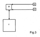
- the expansion device 4 is an electronically controlled expansion valve which comprises an electronic control unit 29 in connection with first and second temperature probes 30, 31.
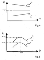
- the refrigerant undergoes a thermodynamic cycle whose efficiency is optimized regardless of the temperature of the refrigerant at the outlet of the gas cooler 2. This optimization is obtained from a maintenance of the average densities D1 and D2 of the refrigerant respectively taken at the inlet and outlet of the gas cooler 2 to a relatively constant value.
- the density D1 of the refrigerant at the inlet of the gas cooler 2 is an increasing linear function of the temperature T of the refrigerant at the outlet of the gas cooler 2
- the density D2 of the refrigerant at the outlet of the gas cooler 2 is a a decreasing linear function of the temperature T of the refrigerant at the outlet of the gas cooler 2
- these two functions have the same respective slope in absolute value. It is advantageously proposed by the present invention to use the increase of the density D1 of the refrigerant at the inlet of the gas cooler 2 to compensate for the lowering of the density D2 of the refrigerant at the outlet of the gas cooler 2.
- the compensation is obtained from a communication on the one hand of the first and second capacitors 13,20 between them and on the other hand of the first capacitor 13 with the second elementary chamber 12, this setting in communication provoking a homogenizing the temperature and the pressure of the refrigerant inside the chamber 26, then a pressure and temperature equilibrium on either side of the membrane 10.
- the compensation is obtained from the implementation of the electronic control unit 29 and temperature probes 30,31.
- thermodynamic cycle that the refrigerant undergoes from a maintenance of the refrigerant at the optimal density "D opt” which induces an optimum efficiency "R1 opt” and “R2 opt According to the respective temperature T1 or T2 of the refrigerant at the outlet of the gas cooler 2, as illustrated in FIG. fig.5 .
- This maintenance is obtained in particular from a suitable dimensioning of the first and second temperature sensors 14,21.
- the refrigerant fluid may be a refrigerant whose critical temperature is of the order of 30 ° C, such as carbon dioxide for example, commonly referred to in the art by the code "R744".
- the thermodynamic cycle that the refrigerant undergoes may be a transcritical cycle such as that illustrated in FIG. fig.6 .
- Such a transcritical cycle comprises a first high-pressure isobaric supercritical stage P1, greater than the critical pressure Pc of the refrigerant, and a second low-pressure isobaric subcritical stage P2, less than the critical pressure Pc of the refrigerant.
- the first high-pressure step P1 takes place inside the gas cooler 2 and the first face 7 of the internal heat exchanger 3 while the second low-pressure step P2 takes place inside the evaporator 5 and the second face 8 of the internal heat exchanger 3.
- the first step is intended to allow a cooling of the refrigerant fluid and Consequently, a cooling of the air in contact with the aforementioned elements where it takes place, while the second step is to allow a heating of the refrigerant and consequently a heating of the air in contact with the elements where it takes place.
- the efficiency R of such a thermodynamic cycle as a function of the pressure P1 of the refrigerant at the outlet of the gas cooler 2 is represented on the fig.7 . It is remarkable that there exists only a value "P1 opt" of the pressure P1 for which the efficiency R is optimized to the value "R opt", the value of "P1 opt” being a function of the temperature of the fluid refrigerant at the outlet of the gas cooler 2.
Landscapes
- Physics & Mathematics (AREA)
- Engineering & Computer Science (AREA)
- Fluid Mechanics (AREA)
- Mechanical Engineering (AREA)
- Thermal Sciences (AREA)
- General Engineering & Computer Science (AREA)
- Air-Conditioning For Vehicles (AREA)
Claims (10)
- Klimatisierungskreislauf, der ein wesentlicher Bestandteil einer Lüftungs-, Heizungs- und/oder Klimaanlage insbesondere eines Fahrzeugs ist, wobei der Klimatisierungskreislauf mindestens einen Gaskühler (2) und mindestens ein Expansionsorgan (4) enthält, das mit Einrichtungen zur Regulierung einer Durchflussmenge eines im Inneren des Klimatisierungskreislaufs fließenden Kühlfluids ausgestattet ist, wobei die Regulierungseinrichtungen eine erste Temperaturmessvorrichtung (14, 30), die am Ausgang des Gaskühlers (2) angeordnet ist, und eine zweite Temperaturmessvorrichtung (21, 31) enthalten, die am Eingang des Gaskühlers (2) angeordnet ist, dadurch gekennzeichnet, dass die Regulierungseinrichtungen einen Behälter (26) enthalten, der aufweist:- eine zweite Elementarkammer (12) des Expansionsorgans (4),- einen ersten Kondensator (13), den ein erster Temperaturfühler (14) aufweist, der die erste Temperaturmessvorrichtung bildet, wobei der erste Kondensator (13) in Wärmeaustausch mit dem aus dem Gaskühler (2) austretenden Kühlfluid steht, und- einen zweiten Kondensator (20), den ein zweiter Temperaturfühler (21) aufweist, der die zweite Temperaturmessvorrichtung bildet, wobei der zweite Kondensator (20) in Wärmeaustausch mit dem in den Gaskühler (2) eintretenden Kühlfluid steht.
- Klimatisierungskreislauf nach Anspruch 1, wobei das Kühlfluid ein Fluid ist, das zum größten Teil aus mindestens einer organischen Verbindung besteht.
- Klimatisierungskreislauf nach einem der Ansprüche 1 bis 2, wobei das Kühlfluid ein Fluid ist, dessen kritische Temperatur zwischen 25°C und 35°C liegt.
- Klimatisierungskreislauf nach Anspruch 3, wobei das Kühlfluid hauptsächlich aus einer Kohlendioxidverbindung besteht.
- Klimatisierungskreislauf nach einem der Ansprüche 1 bis 4, wobei das Expansionsorgan (4) einen Eingang (27) und einen Ausgang (28) eines Kühlfluids enthält, zwischen denen ein Strömungskanal (17) des Kühlfluids ausgebildet ist, wobei das Expansionsorgan (4) außerdem eine Hauptkammer (9) enthält, in der eine Membran (10) untergebracht ist, die die Hauptkammer (9) in zwei Elementarkammern (11, 12) trennt, von denen eine erste Elementarkammer (11) mit dem Strömungskanal (17) gekoppelt ist, während die zweite Elementarkammer (12) mit dem ersten Temperaturfühler (14) gekoppelt ist, wobei der erste Temperaturfühler (14) mit dem zweiten Temperaturfühler (21) gekoppelt ist.
- Klimatisierungskreislauf nach Anspruch 5, wobei die Kopplung des ersten Temperaturfühlers (14) mit dem zweiten Temperaturfühler (21) ausgehend von einer Verbindung eines ersten Kondensators (13), den der erste Temperaturfühler (14) aufweist, mit einem zweiten Kondensator (20), den der zweite Temperaturfühler (21) aufweist, erhalten wird, wobei diese Verbindung mittels einer ersten Kapillarleitung (22) gebildet wird.
- Klimatisierungskreislauf nach Anspruch 6, wobei die Kopplung des ersten Temperaturfühlers (14) mit der zweiten Elementarkammer (12) ausgehend von einer Verbindung des ersten Kondensators (13) mit der zweiten Elementarkammer (12) erhalten wird, wobei diese Verbindung mittels einer zweiten Kapillarleitung (16) gebildet wird.
- Klimatisierungskreislauf nach den Ansprüchen 6 und 7, wobei die zweite Elementarkammer (12), der erste Kondensator (13), der zweite Kondensator (20), die erste Kapillarleitung (22) und die zweite Kapillarleitung (16) zusammen einen Sicherheitsbehälter (26) eines Steuerfluids formen.
- Klimatisierungskreislauf nach Anspruch 8, wobei das Steuerfluid unterschiedslos entweder gleich dem oder anders als das Kühlfluid ist.
- Klimatisierungskreislauf nach einem der Ansprüche 6 bis 9, wobei jeder der ersten (13) und zweiten Kondensatoren (20) von einem Rohr (15, 23) begrenzt wird, das aus einem wärmeleitenden Material hergestellt ist.
Priority Applications (1)
| Application Number | Priority Date | Filing Date | Title |
|---|---|---|---|
| PL07122342T PL1930670T3 (pl) | 2006-12-08 | 2007-12-05 | Rozprężający człon łączący w sobie dwa czujniki temperatury czynnika chłodniczego, które są przeznaczone odpowiednio do umieszczenia na wlocie i na wylocie chłodnicy gazu |
Applications Claiming Priority (1)
| Application Number | Priority Date | Filing Date | Title |
|---|---|---|---|
| FR0610701A FR2909752B1 (fr) | 2006-12-08 | 2006-12-08 | Organe de detente associant deux capteurs de temperature d'un fluide refrigerant qui sont destines a etre respectivement places en entree et en sortie d'un refroidisseur de gaz. |
Publications (2)
| Publication Number | Publication Date |
|---|---|
| EP1930670A1 EP1930670A1 (de) | 2008-06-11 |
| EP1930670B1 true EP1930670B1 (de) | 2014-02-26 |
Family
ID=38461124
Family Applications (1)
| Application Number | Title | Priority Date | Filing Date |
|---|---|---|---|
| EP07122342.4A Not-in-force EP1930670B1 (de) | 2006-12-08 | 2007-12-05 | Druckreduzierorgan, das 2 Temperaturfühler einer Kühlflüssigkeit umfasst, die am Eingang und Ausgang eines Gaskühlers angebracht werden sollen |
Country Status (3)
| Country | Link |
|---|---|
| EP (1) | EP1930670B1 (de) |
| FR (1) | FR2909752B1 (de) |
| PL (1) | PL1930670T3 (de) |
Family Cites Families (12)
| Publication number | Priority date | Publication date | Assignee | Title |
|---|---|---|---|---|
| US2199498A (en) * | 1938-10-27 | 1940-05-07 | Gen Motors Corp | Refrigerating apparatus |
| US2538861A (en) * | 1947-10-01 | 1951-01-23 | Detroit Lubricator Co | Refrigeration expansion valve |
| US2752760A (en) * | 1954-06-04 | 1956-07-03 | Gen Motors Corp | Expansion valve with bulb control |
| AU7321881A (en) * | 1981-05-20 | 1982-12-07 | Richard H. Alsenz | Method and apparatus for controlling operation of a thermostatic expansion valve |
| NL9000744A (nl) * | 1990-03-29 | 1991-10-16 | Weinand Antonius Maria Stapelb | Geoptimaliseerd thermostatisch expansieventiel en een daarvan voorziene koelmachine. |
| DE19506143C2 (de) * | 1995-02-22 | 1998-01-15 | Danfoss As | Verfahren zur Regelung der Überhitzungstemperatur des Kältemittels in einer Verdampfereinrichtung einer Kälte- oder Wärmepumpanlage und Vorrichtung zur Durchführung des Verfahrens |
| JPH0949662A (ja) * | 1995-08-09 | 1997-02-18 | Aisin Seiki Co Ltd | 圧縮式空調機 |
| DE19647718C2 (de) * | 1996-11-19 | 1998-09-24 | Danfoss As | Verfahren zur Regelung einer Kälteanlage sowie Kälteanlage und Expansionsventil |
| JP2001147048A (ja) * | 1999-11-19 | 2001-05-29 | Sanden Corp | 冷凍回路の過熱度制御装置 |
| JP2004061061A (ja) * | 2002-07-31 | 2004-02-26 | Matsushita Electric Ind Co Ltd | 冷凍サイクル装置およびその運転方法 |
| EP1666817A3 (de) | 2004-12-01 | 2007-01-17 | Fujikoki Corporation | Druckregelventil |
| EP1695849A1 (de) * | 2005-02-28 | 2006-08-30 | Sanyo Electric Co., Ltd. | Kältemittel-Kreislauf |
-
2006
- 2006-12-08 FR FR0610701A patent/FR2909752B1/fr not_active Expired - Fee Related
-
2007
- 2007-12-05 EP EP07122342.4A patent/EP1930670B1/de not_active Not-in-force
- 2007-12-05 PL PL07122342T patent/PL1930670T3/pl unknown
Also Published As
| Publication number | Publication date |
|---|---|
| FR2909752A1 (fr) | 2008-06-13 |
| EP1930670A1 (de) | 2008-06-11 |
| FR2909752B1 (fr) | 2012-12-21 |
| PL1930670T3 (pl) | 2014-07-31 |
Similar Documents
| Publication | Publication Date | Title |
|---|---|---|
| FR3076342B1 (fr) | Circuit de conditionnement thermique | |
| EP0960755A1 (de) | Klimakreislauf unter Verwendung einer Kühlflüssigkeit im superkritischen Zustand, insbesondere für Fahrzeuge | |
| EP2108910B1 (de) | Innere wärmetauscher umfassend ein wärmespeichermittel und kreislauf mit einem solchen wärmetauscher | |
| EP3781882B1 (de) | Wärmeregelungsvorrichtung für ein kraftfahrzeug | |
| Brito et al. | Influence of heat pipe operating temperature on exhaust heat thermoelectric generation | |
| FR2936596A1 (fr) | Ejecteur pour une boucle de climatisation | |
| EP2179875B1 (de) | Klimaanlage mit einem Speichermodul in einem Sekundärkreislauf | |
| EP1325269A1 (de) | Fahrzeugklimaanlage unter verwendung eines überkritischen kreislaufes | |
| FR2905633A1 (fr) | Boucle de climatisation d'un vehicule automobile dont le fluide refrigerant est a base de 1,1,1,2-tetrafluoroproprene et de trifluoroiodomethane | |
| EP1930670B1 (de) | Druckreduzierorgan, das 2 Temperaturfühler einer Kühlflüssigkeit umfasst, die am Eingang und Ausgang eines Gaskühlers angebracht werden sollen | |
| US6626567B2 (en) | Cooling system for thermal analysis | |
| EP1828559B1 (de) | System zur steuerung der wärmeenergie eines kraftfahrzeugmotors durch einstellen der fluidantriebe des systems | |
| EP3610534A1 (de) | Vorrichtung zur temperaturregelung einer batteriepackung | |
| EP2766206B1 (de) | Druckentlastungsvorrichtung mit einem druckentlastungsmittel und mittel zur umgehung des druckentlastungsmittels | |
| EP2790264A1 (de) | Vorrichtung zur Temperatureinstellung einer Batterie von elektrischen Akkumulatoren eines Kraftfahrzeugs, und mit einer solchen Vorrichtung ausgestattetes Kraftfahrzeug | |
| EP3747080B1 (de) | Verfahren zum kühlen einer stromspeichervorrichtung eines fahrzeugs | |
| WO2023285398A1 (fr) | Enceinte climatique a regulation thermique pour simulateur de mouvements et procede de regulation thermique, kit d'installation | |
| FR2953920A1 (fr) | Systeme de climatisation comprenant un dispositif de controle du givrage d'un echangeur de chaleur constitutif d'une boucle de climatisation; | |
| WO2023026206A1 (fr) | Unite de chauffage et/ou de refroidissement a materiau a changement de phase | |
| EP2400240B1 (de) | Kontrollverfahren einer Lagervorrichtung in einem Kühlmittelkreislauf | |
| FR2945484A1 (fr) | Vehicule comportant un refroidisseur d'air suralimente et procede de rechauffement dudit refroidisseur | |
| FR3082297A1 (fr) | Dispositif de regulation thermique d’au moins un element de stockage d’energie electrique de vehicule automobile | |
| FR3049656A1 (fr) | Systeme de gestion d'air d'admission pour un moteur thermique de vehicule automobile | |
| Yokokawa et al. | 13 SPACE HEATING AND COOLING | |
| WO2014095592A1 (fr) | Systeme de regulation d'une detente d'un fluide refrigerant |
Legal Events
| Date | Code | Title | Description |
|---|---|---|---|
| PUAI | Public reference made under article 153(3) epc to a published international application that has entered the european phase |
Free format text: ORIGINAL CODE: 0009012 |
|
| AK | Designated contracting states |
Kind code of ref document: A1 Designated state(s): AT BE BG CH CY CZ DE DK EE ES FI FR GB GR HU IE IS IT LI LT LU LV MC MT NL PL PT RO SE SI SK TR |
|
| AX | Request for extension of the european patent |
Extension state: AL BA HR MK RS |
|
| 17P | Request for examination filed |
Effective date: 20081124 |
|
| 17Q | First examination report despatched |
Effective date: 20090120 |
|
| AKX | Designation fees paid |
Designated state(s): AT BE BG CH CY CZ DE DK EE ES FI FR GB GR HU IE IS IT LI LT LU LV MC MT NL PL PT RO SE SI SK TR |
|
| RAP3 | Party data changed (applicant data changed or rights of an application transferred) |
Owner name: VALEO SYSTEMES THERMIQUES |
|
| GRAP | Despatch of communication of intention to grant a patent |
Free format text: ORIGINAL CODE: EPIDOSNIGR1 |
|
| INTG | Intention to grant announced |
Effective date: 20130904 |
|
| GRAS | Grant fee paid |
Free format text: ORIGINAL CODE: EPIDOSNIGR3 |
|
| GRAA | (expected) grant |
Free format text: ORIGINAL CODE: 0009210 |
|
| AK | Designated contracting states |
Kind code of ref document: B1 Designated state(s): AT BE BG CH CY CZ DE DK EE ES FI FR GB GR HU IE IS IT LI LT LU LV MC MT NL PL PT RO SE SI SK TR |
|
| REG | Reference to a national code |
Ref country code: GB Ref legal event code: FG4D Free format text: NOT ENGLISH |
|
| REG | Reference to a national code |
Ref country code: CH Ref legal event code: EP |
|
| REG | Reference to a national code |
Ref country code: AT Ref legal event code: REF Ref document number: 653843 Country of ref document: AT Kind code of ref document: T Effective date: 20140315 |
|
| REG | Reference to a national code |
Ref country code: IE Ref legal event code: FG4D Free format text: LANGUAGE OF EP DOCUMENT: FRENCH |
|
| REG | Reference to a national code |
Ref country code: DE Ref legal event code: R096 Ref document number: 602007035184 Country of ref document: DE Effective date: 20140417 |
|
| REG | Reference to a national code |
Ref country code: NL Ref legal event code: VDEP Effective date: 20140226 |
|
| REG | Reference to a national code |
Ref country code: AT Ref legal event code: MK05 Ref document number: 653843 Country of ref document: AT Kind code of ref document: T Effective date: 20140226 |
|
| REG | Reference to a national code |
Ref country code: LT Ref legal event code: MG4D |
|
| PG25 | Lapsed in a contracting state [announced via postgrant information from national office to epo] |
Ref country code: IS Free format text: LAPSE BECAUSE OF FAILURE TO SUBMIT A TRANSLATION OF THE DESCRIPTION OR TO PAY THE FEE WITHIN THE PRESCRIBED TIME-LIMIT Effective date: 20140626 Ref country code: LT Free format text: LAPSE BECAUSE OF FAILURE TO SUBMIT A TRANSLATION OF THE DESCRIPTION OR TO PAY THE FEE WITHIN THE PRESCRIBED TIME-LIMIT Effective date: 20140226 |
|
| REG | Reference to a national code |
Ref country code: PL Ref legal event code: T3 |
|
| PG25 | Lapsed in a contracting state [announced via postgrant information from national office to epo] |
Ref country code: SE Free format text: LAPSE BECAUSE OF FAILURE TO SUBMIT A TRANSLATION OF THE DESCRIPTION OR TO PAY THE FEE WITHIN THE PRESCRIBED TIME-LIMIT Effective date: 20140226 Ref country code: FI Free format text: LAPSE BECAUSE OF FAILURE TO SUBMIT A TRANSLATION OF THE DESCRIPTION OR TO PAY THE FEE WITHIN THE PRESCRIBED TIME-LIMIT Effective date: 20140226 Ref country code: AT Free format text: LAPSE BECAUSE OF FAILURE TO SUBMIT A TRANSLATION OF THE DESCRIPTION OR TO PAY THE FEE WITHIN THE PRESCRIBED TIME-LIMIT Effective date: 20140226 Ref country code: PT Free format text: LAPSE BECAUSE OF FAILURE TO SUBMIT A TRANSLATION OF THE DESCRIPTION OR TO PAY THE FEE WITHIN THE PRESCRIBED TIME-LIMIT Effective date: 20140626 Ref country code: CY Free format text: LAPSE BECAUSE OF FAILURE TO SUBMIT A TRANSLATION OF THE DESCRIPTION OR TO PAY THE FEE WITHIN THE PRESCRIBED TIME-LIMIT Effective date: 20140226 Ref country code: NL Free format text: LAPSE BECAUSE OF FAILURE TO SUBMIT A TRANSLATION OF THE DESCRIPTION OR TO PAY THE FEE WITHIN THE PRESCRIBED TIME-LIMIT Effective date: 20140226 |
|
| PG25 | Lapsed in a contracting state [announced via postgrant information from national office to epo] |
Ref country code: LV Free format text: LAPSE BECAUSE OF FAILURE TO SUBMIT A TRANSLATION OF THE DESCRIPTION OR TO PAY THE FEE WITHIN THE PRESCRIBED TIME-LIMIT Effective date: 20140226 |
|
| PG25 | Lapsed in a contracting state [announced via postgrant information from national office to epo] |
Ref country code: RO Free format text: LAPSE BECAUSE OF FAILURE TO SUBMIT A TRANSLATION OF THE DESCRIPTION OR TO PAY THE FEE WITHIN THE PRESCRIBED TIME-LIMIT Effective date: 20140226 Ref country code: DK Free format text: LAPSE BECAUSE OF FAILURE TO SUBMIT A TRANSLATION OF THE DESCRIPTION OR TO PAY THE FEE WITHIN THE PRESCRIBED TIME-LIMIT Effective date: 20140226 Ref country code: EE Free format text: LAPSE BECAUSE OF FAILURE TO SUBMIT A TRANSLATION OF THE DESCRIPTION OR TO PAY THE FEE WITHIN THE PRESCRIBED TIME-LIMIT Effective date: 20140226 |
|
| REG | Reference to a national code |
Ref country code: DE Ref legal event code: R097 Ref document number: 602007035184 Country of ref document: DE |
|
| PG25 | Lapsed in a contracting state [announced via postgrant information from national office to epo] |
Ref country code: SK Free format text: LAPSE BECAUSE OF FAILURE TO SUBMIT A TRANSLATION OF THE DESCRIPTION OR TO PAY THE FEE WITHIN THE PRESCRIBED TIME-LIMIT Effective date: 20140226 Ref country code: ES Free format text: LAPSE BECAUSE OF FAILURE TO SUBMIT A TRANSLATION OF THE DESCRIPTION OR TO PAY THE FEE WITHIN THE PRESCRIBED TIME-LIMIT Effective date: 20140226 |
|
| PLBE | No opposition filed within time limit |
Free format text: ORIGINAL CODE: 0009261 |
|
| STAA | Information on the status of an ep patent application or granted ep patent |
Free format text: STATUS: NO OPPOSITION FILED WITHIN TIME LIMIT |
|
| 26N | No opposition filed |
Effective date: 20141127 |
|
| REG | Reference to a national code |
Ref country code: DE Ref legal event code: R097 Ref document number: 602007035184 Country of ref document: DE Effective date: 20141127 |
|
| PG25 | Lapsed in a contracting state [announced via postgrant information from national office to epo] |
Ref country code: IT Free format text: LAPSE BECAUSE OF FAILURE TO SUBMIT A TRANSLATION OF THE DESCRIPTION OR TO PAY THE FEE WITHIN THE PRESCRIBED TIME-LIMIT Effective date: 20140226 |
|
| PG25 | Lapsed in a contracting state [announced via postgrant information from national office to epo] |
Ref country code: SI Free format text: LAPSE BECAUSE OF FAILURE TO SUBMIT A TRANSLATION OF THE DESCRIPTION OR TO PAY THE FEE WITHIN THE PRESCRIBED TIME-LIMIT Effective date: 20140226 |
|
| PG25 | Lapsed in a contracting state [announced via postgrant information from national office to epo] |
Ref country code: BE Free format text: LAPSE BECAUSE OF NON-PAYMENT OF DUE FEES Effective date: 20141231 |
|
| PG25 | Lapsed in a contracting state [announced via postgrant information from national office to epo] |
Ref country code: LU Free format text: LAPSE BECAUSE OF FAILURE TO SUBMIT A TRANSLATION OF THE DESCRIPTION OR TO PAY THE FEE WITHIN THE PRESCRIBED TIME-LIMIT Effective date: 20141205 |
|
| REG | Reference to a national code |
Ref country code: CH Ref legal event code: PL |
|
| GBPC | Gb: european patent ceased through non-payment of renewal fee |
Effective date: 20141205 |
|
| REG | Reference to a national code |
Ref country code: IE Ref legal event code: MM4A |
|
| PG25 | Lapsed in a contracting state [announced via postgrant information from national office to epo] |
Ref country code: GB Free format text: LAPSE BECAUSE OF NON-PAYMENT OF DUE FEES Effective date: 20141205 Ref country code: CH Free format text: LAPSE BECAUSE OF NON-PAYMENT OF DUE FEES Effective date: 20141231 Ref country code: LI Free format text: LAPSE BECAUSE OF NON-PAYMENT OF DUE FEES Effective date: 20141231 Ref country code: IE Free format text: LAPSE BECAUSE OF NON-PAYMENT OF DUE FEES Effective date: 20141205 |
|
| REG | Reference to a national code |
Ref country code: FR Ref legal event code: PLFP Year of fee payment: 9 |
|
| PGFP | Annual fee paid to national office [announced via postgrant information from national office to epo] |
Ref country code: DE Payment date: 20151209 Year of fee payment: 9 |
|
| PGFP | Annual fee paid to national office [announced via postgrant information from national office to epo] |
Ref country code: CZ Payment date: 20151123 Year of fee payment: 9 Ref country code: PL Payment date: 20151201 Year of fee payment: 9 |
|
| PG25 | Lapsed in a contracting state [announced via postgrant information from national office to epo] |
Ref country code: BG Free format text: LAPSE BECAUSE OF FAILURE TO SUBMIT A TRANSLATION OF THE DESCRIPTION OR TO PAY THE FEE WITHIN THE PRESCRIBED TIME-LIMIT Effective date: 20140226 Ref country code: MC Free format text: LAPSE BECAUSE OF FAILURE TO SUBMIT A TRANSLATION OF THE DESCRIPTION OR TO PAY THE FEE WITHIN THE PRESCRIBED TIME-LIMIT Effective date: 20140226 |
|
| PGFP | Annual fee paid to national office [announced via postgrant information from national office to epo] |
Ref country code: FR Payment date: 20151231 Year of fee payment: 9 |
|
| PG25 | Lapsed in a contracting state [announced via postgrant information from national office to epo] |
Ref country code: GR Free format text: LAPSE BECAUSE OF FAILURE TO SUBMIT A TRANSLATION OF THE DESCRIPTION OR TO PAY THE FEE WITHIN THE PRESCRIBED TIME-LIMIT Effective date: 20140527 |
|
| PG25 | Lapsed in a contracting state [announced via postgrant information from national office to epo] |
Ref country code: MT Free format text: LAPSE BECAUSE OF FAILURE TO SUBMIT A TRANSLATION OF THE DESCRIPTION OR TO PAY THE FEE WITHIN THE PRESCRIBED TIME-LIMIT Effective date: 20140226 Ref country code: HU Free format text: LAPSE BECAUSE OF FAILURE TO SUBMIT A TRANSLATION OF THE DESCRIPTION OR TO PAY THE FEE WITHIN THE PRESCRIBED TIME-LIMIT; INVALID AB INITIO Effective date: 20071205 Ref country code: TR Free format text: LAPSE BECAUSE OF FAILURE TO SUBMIT A TRANSLATION OF THE DESCRIPTION OR TO PAY THE FEE WITHIN THE PRESCRIBED TIME-LIMIT Effective date: 20140226 |
|
| REG | Reference to a national code |
Ref country code: DE Ref legal event code: R119 Ref document number: 602007035184 Country of ref document: DE |
|
| PG25 | Lapsed in a contracting state [announced via postgrant information from national office to epo] |
Ref country code: CZ Free format text: LAPSE BECAUSE OF NON-PAYMENT OF DUE FEES Effective date: 20161205 |
|
| REG | Reference to a national code |
Ref country code: FR Ref legal event code: ST Effective date: 20170831 |
|
| PG25 | Lapsed in a contracting state [announced via postgrant information from national office to epo] |
Ref country code: FR Free format text: LAPSE BECAUSE OF NON-PAYMENT OF DUE FEES Effective date: 20170102 |
|
| PG25 | Lapsed in a contracting state [announced via postgrant information from national office to epo] |
Ref country code: DE Free format text: LAPSE BECAUSE OF NON-PAYMENT OF DUE FEES Effective date: 20170701 |
|
| PG25 | Lapsed in a contracting state [announced via postgrant information from national office to epo] |
Ref country code: PL Free format text: LAPSE BECAUSE OF NON-PAYMENT OF DUE FEES Effective date: 20161205 |