EP1828559B1 - System zur steuerung der wärmeenergie eines kraftfahrzeugmotors durch einstellen der fluidantriebe des systems - Google Patents
System zur steuerung der wärmeenergie eines kraftfahrzeugmotors durch einstellen der fluidantriebe des systems Download PDFInfo
- Publication number
- EP1828559B1 EP1828559B1 EP04816480A EP04816480A EP1828559B1 EP 1828559 B1 EP1828559 B1 EP 1828559B1 EP 04816480 A EP04816480 A EP 04816480A EP 04816480 A EP04816480 A EP 04816480A EP 1828559 B1 EP1828559 B1 EP 1828559B1
- Authority
- EP
- European Patent Office
- Prior art keywords
- temperature
- low
- circuit
- management system
- actuators
- Prior art date
- Legal status (The legal status is an assumption and is not a legal conclusion. Google has not performed a legal analysis and makes no representation as to the accuracy of the status listed.)
- Active
Links
- 239000012530 fluid Substances 0.000 title claims abstract description 19
- 238000001816 cooling Methods 0.000 claims abstract description 37
- 238000004378 air conditioning Methods 0.000 claims description 31
- 239000013529 heat transfer fluid Substances 0.000 claims description 25
- 238000004422 calculation algorithm Methods 0.000 claims description 9
- 239000002826 coolant Substances 0.000 claims description 9
- 239000007788 liquid Substances 0.000 claims description 5
- 230000001276 controlling effect Effects 0.000 claims description 4
- 230000001105 regulatory effect Effects 0.000 claims description 3
- 238000002485 combustion reaction Methods 0.000 claims 1
- 239000012809 cooling fluid Substances 0.000 abstract description 7
- 239000003570 air Substances 0.000 description 58
- XLYOFNOQVPJJNP-UHFFFAOYSA-N water Substances O XLYOFNOQVPJJNP-UHFFFAOYSA-N 0.000 description 21
- 239000012080 ambient air Substances 0.000 description 5
- 101100371857 Caenorhabditis elegans unc-71 gene Proteins 0.000 description 3
- LYCAIKOWRPUZTN-UHFFFAOYSA-N Ethylene glycol Chemical compound OCCO LYCAIKOWRPUZTN-UHFFFAOYSA-N 0.000 description 3
- 239000007789 gas Substances 0.000 description 2
- 238000010438 heat treatment Methods 0.000 description 2
- 239000003507 refrigerant Substances 0.000 description 2
- 238000011144 upstream manufacturing Methods 0.000 description 2
- CYJRNFFLTBEQSQ-UHFFFAOYSA-N 8-(3-methyl-1-benzothiophen-5-yl)-N-(4-methylsulfonylpyridin-3-yl)quinoxalin-6-amine Chemical compound CS(=O)(=O)C1=C(C=NC=C1)NC=1C=C2N=CC=NC2=C(C=1)C=1C=CC2=C(C(=CS2)C)C=1 CYJRNFFLTBEQSQ-UHFFFAOYSA-N 0.000 description 1
- 101100054862 Caenorhabditis elegans adm-4 gene Proteins 0.000 description 1
- 230000002528 anti-freeze Effects 0.000 description 1
- 239000003638 chemical reducing agent Substances 0.000 description 1
- 239000000112 cooling gas Substances 0.000 description 1
- 239000000498 cooling water Substances 0.000 description 1
- 238000010586 diagram Methods 0.000 description 1
- 230000000694 effects Effects 0.000 description 1
- 230000007704 transition Effects 0.000 description 1
Images


Classifications
-
- F—MECHANICAL ENGINEERING; LIGHTING; HEATING; WEAPONS; BLASTING
- F01—MACHINES OR ENGINES IN GENERAL; ENGINE PLANTS IN GENERAL; STEAM ENGINES
- F01P—COOLING OF MACHINES OR ENGINES IN GENERAL; COOLING OF INTERNAL-COMBUSTION ENGINES
- F01P7/00—Controlling of coolant flow
- F01P7/14—Controlling of coolant flow the coolant being liquid
- F01P7/16—Controlling of coolant flow the coolant being liquid by thermostatic control
- F01P7/165—Controlling of coolant flow the coolant being liquid by thermostatic control characterised by systems with two or more loops
-
- B—PERFORMING OPERATIONS; TRANSPORTING
- B60—VEHICLES IN GENERAL
- B60H—ARRANGEMENTS OF HEATING, COOLING, VENTILATING OR OTHER AIR-TREATING DEVICES SPECIALLY ADAPTED FOR PASSENGER OR GOODS SPACES OF VEHICLES
- B60H1/00—Heating, cooling or ventilating [HVAC] devices
-
- F—MECHANICAL ENGINEERING; LIGHTING; HEATING; WEAPONS; BLASTING
- F01—MACHINES OR ENGINES IN GENERAL; ENGINE PLANTS IN GENERAL; STEAM ENGINES
- F01P—COOLING OF MACHINES OR ENGINES IN GENERAL; COOLING OF INTERNAL-COMBUSTION ENGINES
- F01P3/00—Liquid cooling
- F01P3/20—Cooling circuits not specific to a single part of engine or machine
-
- F—MECHANICAL ENGINEERING; LIGHTING; HEATING; WEAPONS; BLASTING
- F01—MACHINES OR ENGINES IN GENERAL; ENGINE PLANTS IN GENERAL; STEAM ENGINES
- F01P—COOLING OF MACHINES OR ENGINES IN GENERAL; COOLING OF INTERNAL-COMBUSTION ENGINES
- F01P7/00—Controlling of coolant flow
- F01P7/02—Controlling of coolant flow the coolant being cooling-air
- F01P7/04—Controlling of coolant flow the coolant being cooling-air by varying pump speed, e.g. by changing pump-drive gear ratio
- F01P7/048—Controlling of coolant flow the coolant being cooling-air by varying pump speed, e.g. by changing pump-drive gear ratio using electrical drives
-
- F—MECHANICAL ENGINEERING; LIGHTING; HEATING; WEAPONS; BLASTING
- F02—COMBUSTION ENGINES; HOT-GAS OR COMBUSTION-PRODUCT ENGINE PLANTS
- F02B—INTERNAL-COMBUSTION PISTON ENGINES; COMBUSTION ENGINES IN GENERAL
- F02B29/00—Engines characterised by provision for charging or scavenging not provided for in groups F02B25/00, F02B27/00 or F02B33/00 - F02B39/00; Details thereof
- F02B29/04—Cooling of air intake supply
- F02B29/0406—Layout of the intake air cooling or coolant circuit
- F02B29/0437—Liquid cooled heat exchangers
- F02B29/0443—Layout of the coolant or refrigerant circuit
-
- F—MECHANICAL ENGINEERING; LIGHTING; HEATING; WEAPONS; BLASTING
- F02—COMBUSTION ENGINES; HOT-GAS OR COMBUSTION-PRODUCT ENGINE PLANTS
- F02B—INTERNAL-COMBUSTION PISTON ENGINES; COMBUSTION ENGINES IN GENERAL
- F02B29/00—Engines characterised by provision for charging or scavenging not provided for in groups F02B25/00, F02B27/00 or F02B33/00 - F02B39/00; Details thereof
- F02B29/04—Cooling of air intake supply
- F02B29/0493—Controlling the air charge temperature
-
- F—MECHANICAL ENGINEERING; LIGHTING; HEATING; WEAPONS; BLASTING
- F01—MACHINES OR ENGINES IN GENERAL; ENGINE PLANTS IN GENERAL; STEAM ENGINES
- F01P—COOLING OF MACHINES OR ENGINES IN GENERAL; COOLING OF INTERNAL-COMBUSTION ENGINES
- F01P3/00—Liquid cooling
- F01P3/18—Arrangements or mounting of liquid-to-air heat-exchangers
- F01P2003/182—Arrangements or mounting of liquid-to-air heat-exchangers with multiple heat-exchangers
-
- F—MECHANICAL ENGINEERING; LIGHTING; HEATING; WEAPONS; BLASTING
- F01—MACHINES OR ENGINES IN GENERAL; ENGINE PLANTS IN GENERAL; STEAM ENGINES
- F01P—COOLING OF MACHINES OR ENGINES IN GENERAL; COOLING OF INTERNAL-COMBUSTION ENGINES
- F01P3/00—Liquid cooling
- F01P3/18—Arrangements or mounting of liquid-to-air heat-exchangers
- F01P2003/187—Arrangements or mounting of liquid-to-air heat-exchangers arranged in series
-
- F—MECHANICAL ENGINEERING; LIGHTING; HEATING; WEAPONS; BLASTING
- F01—MACHINES OR ENGINES IN GENERAL; ENGINE PLANTS IN GENERAL; STEAM ENGINES
- F01P—COOLING OF MACHINES OR ENGINES IN GENERAL; COOLING OF INTERNAL-COMBUSTION ENGINES
- F01P5/00—Pumping cooling-air or liquid coolants
- F01P5/10—Pumping liquid coolant; Arrangements of coolant pumps
- F01P2005/105—Using two or more pumps
-
- F—MECHANICAL ENGINEERING; LIGHTING; HEATING; WEAPONS; BLASTING
- F01—MACHINES OR ENGINES IN GENERAL; ENGINE PLANTS IN GENERAL; STEAM ENGINES
- F01P—COOLING OF MACHINES OR ENGINES IN GENERAL; COOLING OF INTERNAL-COMBUSTION ENGINES
- F01P5/00—Pumping cooling-air or liquid coolants
- F01P5/10—Pumping liquid coolant; Arrangements of coolant pumps
- F01P5/12—Pump-driving arrangements
- F01P2005/125—Driving auxiliary pumps electrically
-
- F—MECHANICAL ENGINEERING; LIGHTING; HEATING; WEAPONS; BLASTING
- F01—MACHINES OR ENGINES IN GENERAL; ENGINE PLANTS IN GENERAL; STEAM ENGINES
- F01P—COOLING OF MACHINES OR ENGINES IN GENERAL; COOLING OF INTERNAL-COMBUSTION ENGINES
- F01P2025/00—Measuring
- F01P2025/04—Pressure
-
- F—MECHANICAL ENGINEERING; LIGHTING; HEATING; WEAPONS; BLASTING
- F01—MACHINES OR ENGINES IN GENERAL; ENGINE PLANTS IN GENERAL; STEAM ENGINES
- F01P—COOLING OF MACHINES OR ENGINES IN GENERAL; COOLING OF INTERNAL-COMBUSTION ENGINES
- F01P2025/00—Measuring
- F01P2025/08—Temperature
- F01P2025/13—Ambient temperature
-
- F—MECHANICAL ENGINEERING; LIGHTING; HEATING; WEAPONS; BLASTING
- F01—MACHINES OR ENGINES IN GENERAL; ENGINE PLANTS IN GENERAL; STEAM ENGINES
- F01P—COOLING OF MACHINES OR ENGINES IN GENERAL; COOLING OF INTERNAL-COMBUSTION ENGINES
- F01P2025/00—Measuring
- F01P2025/08—Temperature
- F01P2025/32—Engine outcoming fluid temperature
-
- F—MECHANICAL ENGINEERING; LIGHTING; HEATING; WEAPONS; BLASTING
- F01—MACHINES OR ENGINES IN GENERAL; ENGINE PLANTS IN GENERAL; STEAM ENGINES
- F01P—COOLING OF MACHINES OR ENGINES IN GENERAL; COOLING OF INTERNAL-COMBUSTION ENGINES
- F01P2025/00—Measuring
- F01P2025/08—Temperature
- F01P2025/42—Intake manifold temperature
-
- F—MECHANICAL ENGINEERING; LIGHTING; HEATING; WEAPONS; BLASTING
- F01—MACHINES OR ENGINES IN GENERAL; ENGINE PLANTS IN GENERAL; STEAM ENGINES
- F01P—COOLING OF MACHINES OR ENGINES IN GENERAL; COOLING OF INTERNAL-COMBUSTION ENGINES
- F01P2060/00—Cooling circuits using auxiliaries
- F01P2060/02—Intercooler
-
- F—MECHANICAL ENGINEERING; LIGHTING; HEATING; WEAPONS; BLASTING
- F01—MACHINES OR ENGINES IN GENERAL; ENGINE PLANTS IN GENERAL; STEAM ENGINES
- F01P—COOLING OF MACHINES OR ENGINES IN GENERAL; COOLING OF INTERNAL-COMBUSTION ENGINES
- F01P2060/00—Cooling circuits using auxiliaries
- F01P2060/08—Cabin heater
-
- F—MECHANICAL ENGINEERING; LIGHTING; HEATING; WEAPONS; BLASTING
- F01—MACHINES OR ENGINES IN GENERAL; ENGINE PLANTS IN GENERAL; STEAM ENGINES
- F01P—COOLING OF MACHINES OR ENGINES IN GENERAL; COOLING OF INTERNAL-COMBUSTION ENGINES
- F01P2060/00—Cooling circuits using auxiliaries
- F01P2060/14—Condenser
-
- Y—GENERAL TAGGING OF NEW TECHNOLOGICAL DEVELOPMENTS; GENERAL TAGGING OF CROSS-SECTIONAL TECHNOLOGIES SPANNING OVER SEVERAL SECTIONS OF THE IPC; TECHNICAL SUBJECTS COVERED BY FORMER USPC CROSS-REFERENCE ART COLLECTIONS [XRACs] AND DIGESTS
- Y02—TECHNOLOGIES OR APPLICATIONS FOR MITIGATION OR ADAPTATION AGAINST CLIMATE CHANGE
- Y02T—CLIMATE CHANGE MITIGATION TECHNOLOGIES RELATED TO TRANSPORTATION
- Y02T10/00—Road transport of goods or passengers
- Y02T10/10—Internal combustion engine [ICE] based vehicles
- Y02T10/12—Improving ICE efficiencies
Definitions
- the invention relates to a system for managing the thermal energy of a motor vehicle.
- thermo energy management system developed by a motor vehicle engine, the system comprising a high temperature circuit traversed by a heat transfer fluid at high temperature and integrating the vehicle engine and a cooling radiator.
- high temperature in which the heat transfer fluid at high temperature is in exchange relationship with a cooling fluid
- low temperature circuit traversed by a heat transfer fluid at low temperature and incorporating a low temperature cooling radiator in which the heat transfer fluid at low temperature is in heat exchange relation with a cooling fluid
- the high temperature cooling circuit is used more particularly for cooling the engine of the vehicle.
- the heat transfer fluid at high temperature circulates at an elevated temperature generally between 85 ° C and 100 ° C.
- the heat transfer fluid In the circuit at low temperature, the heat transfer fluid must be at a lower temperature, for example of the order of 40 ° C to 60 ° C. This is particularly the case when the low temperature circuit incorporates the air conditioning condenser. It is indeed envisaged, in the near future, to cool this condenser with a coolant liquid, for example water, and not air as in conventional air conditioning circuits. It is therefore necessary to produce the cold heat transfer fluid optimizing the management of the thermal energy of the engine.
- a management system of this type does not take into account all the external parameters so that the management of thermal energy is not optimized.
- the present invention specifically relates to a thermal energy management system that overcomes these disadvantages.
- This object is achieved by the fact that said system comprises one or second actuators for circulating the cooling fluids in the radiator at high temperature and in the radiator at low temperature and in that it furthermore comprises suitable sensors. capturing parameters representative of the cooling requirements of the high temperature circuit and / or the low temperature circuit and supplying these parameters to a control unit of said system, said control unit regulating the first and second actuators according to these settings.
- the management system of the invention makes it possible to regulate not only the circulation of heat transfer fluids at high and low temperatures which circulate respectively in the circuit at high temperature and in the circuit at low temperature, but also the external fluids (it may be the same external fluid) that serve to extract the calories from the two cooling circuits. Taking into account at least one parameter relating to external cooling fluids is essential to ensure good performance, in particular of the low temperature cooling circuit.
- said first actuators are circulation pumps mounted respectively on the high temperature circuit and the low temperature circuit.
- High and low temperature radiators are liquid gas radiators and the cooling gas of these radiators is the atmospheric air outside the vehicle.
- the actuator (s) of the high and low temperature radiators are constituted by motor-fan units forcing a circulation of external cooling air through these radiators.
- the control unit is arranged to use the capacity of the circulation pump of the circuit at low temperature before that of the motor-fan unit.
- the parameters supplied to the control unit comprise at least one parameter relating to the first actuators and at least one parameter relating to the second actuators.
- the circulation pump of the high temperature circuit is a mechanical pump driven directly by the motor, its rotational speed can not be regulated since it depends exclusively on the speed of rotation of the motor. As a result, in this case, it is sufficient to regulate the actuator of the heat transfer fluid of the low temperature circuit, namely the circulation pump of this circuit.
- the first and second actuators are controlled by a variation of their supply voltage, in other words by a variation of the supply voltage of the electric motor which drives the pump or the fan.
- the parameters representative of the cooling requirements of the high and / or low temperature circuits may comprise at least the temperature of the heat transfer liquid of the high temperature circuit at the engine outlet, the engine intake air temperature and the engine temperature. temperature of the outside atmospheric air.
- the parameters representative of the cooling requirements of the high and / or low temperature circuits further comprise the pressure of the cryogenic fluid of the air conditioning circuit at the outlet of the compressor.
- Representative parameters of cooling requirements for high and / or low temperature circuits include furthermore advantageously the temperature of the heat transfer liquid at the outlet of the radiator at low temperature and the speed of the vehicle.
- control unit uses a calculation algorithm for each of the actuators, this actuator creating a series of intermediate values U1, U2, U3 ... according to the parameters supplied by the sensors and select the intermediate variable. higher as the supply voltage of this actuator.
- the intermediate variables are generated by comparing the value of the parameter with lower and upper threshold values of this parameter.
- a convenient way to implement the invention is to provide that the above calculation algorithms are designed to use the capacity of the circulating pump of the low temperature circuit before that of the motor-fan unit.
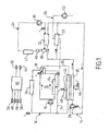
- the system of management of the thermal energy represented on the figure 1 comprises a high temperature circuit designated by the general reference 12 and a low temperature circuit designated by the general reference 14.
- the high temperature circuit 12 comprises a motor vehicle engine 10, a circulation pump 16 for circulating a heat transfer fluid in the high temperature circuit.
- This heat transfer fluid may be the same as that of the low temperature circuit 14 or the two circuits may use different fluids.
- a thermostat or a thermostatic valve 18 is placed at the outlet of the engine 10 to circulate the coolant, either in a line 20 having a high temperature heat exchanger 22, or in a bypass line 24.
- the heat exchanger 22 constitutes the main radiator of the vehicle which is mainly used for cooling the engine 10.
- the high temperature circuit 12 further comprises a heating radiator 26, also called heater, for heating the passenger compartment of the vehicle.
- the high temperature circuit 12 may also comprise other heat exchangers (not shown), for example an oil cooler, an exhaust gas cooler, etc.
- the low temperature circuit 14 comprises a circulation pump 28. While the pump 16 of the high temperature circuit may be a mechanical pump, the pump 28 is still an electric pump.
- the circuit also includes a low temperature heat exchanger 30 and a condenser 32 forming part of an air conditioning system of the passenger compartment of the vehicle, generally designated by the general reference 34.
- the air conditioning circuit is traversed by a refrigerant under the action of a compressor 36 placed upstream of the condenser 32.
- the refrigerant passes successively through the condenser 32, a tank 38, also called “bottle”, a pressure reducer 40, a evaporator 42, before returning to the compressor 36.
- the operation of the air conditioning circuit is conventional. As a result, it will not be described in detail.
- the condenser 32 is particular in the sense that it is cooled by the heat transfer fluid of the low temperature circuit 14 instead of being cooled by an outside air flow, as in conventional air conditioning circuits.
- the circuits 12 and 14 may be interconnected with each other by switching means for passing the heat transfer fluid from one circuit to the other. Or, as in the example shown, the circuits can be independent of each other. In this second case, it can be provided to use different heat transfer fluids for each of the circuits.
- the radiator 22 of the high temperature circuit 12 and the radiator 30 of the low temperature circuit 14 are arranged parallel to each other and
- the advantageous arrangement makes it possible to use, in a conventional manner, a single motor-fan unit 48 for forcing the flow of air through the radiators 22 and 30.
- this embodiment implies that it is not possible to control separately the air flows that pass through each of the two radiators. Therefore, in an alternative embodiment, the radiators 22 and 30 may not be traversed by the same air flow and be equipped with independent motor-fan units.
- the management system of the figure 1 also comprises a supply air intake line in the engine 10, designated by the general reference 50. It comprises a compressor 52 which compresses the ambient air, which has the effect of raising its temperature significantly. Accordingly, the latter must be cooled in the charge air cooler 33 mentioned above and part of the low temperature circuit 14. The cooled air is admitted into the intake manifolds 54 of the engine 10.
- the thermal energy management system that has just been described is equipped with a certain number of sensors that make it possible to capture operating parameters representative of the cooling requirements of the circuit at low temperature 14, but also of the high-temperature circuit. temperature 12.
- the sensor 58 provides information which informs on the need for cooling of the low temperature circuit 14 but also of the high temperature circuit 12. A low outside air temperature results in a decrease in the need for cooling and conversely, an air temperature high ambient results in an increased need for cooling.
- the parameters supplied by the sensors 56 and 58 are introduced into a control unit 60 which regulates the voltage 62 of the pump 28 of the low temperature circuit 14 and the supply voltage 64 of the motor-fan unit 48.
- the pump 16 constitutes an actuator of the heat transfer fluid of the high temperature circuit 12 and the circulation pump 28 constitutes an actuator of the coolant of the low temperature circuit 14.
- the motor-fan unit 48 is a coolant actuator.
- the actuator 48 is common to both circuits 12 and 14 but, as has been explained, each circuit could have its own radiator 22 and 30. own actuator.
- the control unit 60 regulates the circulation of the coolant at least in the low temperature circuit 14 and also the circulation of the cooling air 46 forced by the actuator 48. therefore to control the two fluids that interact in the operation of the two cooling circuits and not one.
- a number of additional sensors can be provided which make it possible to improve and clarify the knowledge of the cooling requirements.
- a sensor 66 for measuring the temperature of the intake air at the outlet of the charge air cooler 33
- a sensor 68 installed on the air conditioning circuit 34 and which measures the maximum pressure of the cryogenic fluid at the outlet of the compressor 36.
- This system could be further completed by additional sensors, for example a sensor measuring the outlet temperature of the water after the low temperature radiator 30 or vehicle speed sensor, for example.
- control parameters are read in step 100.
- these parameters are three in number, namely the high pressure of the air conditioning circuit HP Clim, the air temperature of admission T air Adm and the ambient air temperature T air Amb.
- a test is performed on the water-charge air cooler 33 by comparing the temperature of the intake air T Air Adm with a high threshold value T air adm 1, for example 40 ° C. If the temperature of the intake air is not lower than this high threshold value, the intermediate variable U 1 pump is equal to a function of the air temperature f (T air) at step 102 If the temperature of the intake air is lower than the high threshold value T air adm 1, it is compared to a step 103 to a low threshold value T air adm 2. This low threshold value is for example of 20 ° C. If the temperature of the intake air is not greater than the low threshold value, the intermediate variable U 1 pump takes the value zero in step 104. Otherwise, it takes a minimum value U min. pump at step 105.
- step 106 the high pressure of the air conditioning circuit HP Clim is compared, that is to say the value of the pressure of the cryogenic fluid at the outlet of the compressor, at a pressure of HP Clim high threshold value 1.
- This high threshold pressure is, for example, 8 bar.
- the value of the high pressure of the air conditioning circuit HP Clim is not lower than the high threshold value HP Clim 1, the value of the intermediate variable U 2 pump is equal to a function of the high pressure, f (HP clim), the air conditioning circuit in step 107. If, on the contrary, the high pressure of the air conditioning circuit is lower than the high threshold value HP Clim 1, it is compared to a step 108 to a low threshold value HP Clim 2, for example 4 bars. If HP Clim is not greater than the low threshold value, the intermediate variable U 2 pump is equal to zero in step 109. In the opposite case, it is equal to a minimum value U min pump in step 110.
- a test is made on the motor-fan unit to determine the third intermediate variable U 3 pump.
- the ambient air temperature, T air amb is compared with a threshold value of the ambient air T amb min, set for example at 20 ° C, at step 111. If the air temperature ambient is below this threshold value, the variable U 3 pump takes the value zero in step 112. In the opposite case, the intermediate variable U 3 pump takes a minimum value U min pump in step 113.
- step 114 the control flowchart determines the final value of the supply voltage of the electric pump of the low temperature circuit U pump. This value is equal to the maximum of the three intermediate variables U1, U2, U3. After that, the cycle starts again and new parameter values are read.
- the intermediate variable U 2 is a function 107 of the high pressure of the air conditioning circuit.
- this function consists of two line segments 115 and 116.
- the variable U2 increases proportionally with the high pressure of the air conditioning circuit until reaching a value U max.
- the control flow chart of the pump shown on the figure 2 corresponds to the case where the low temperature circuit comprises both a charge air cooler and an air conditioning circuit of the passenger compartment of the vehicle comprising a water condenser. If there is a situation where the vehicle does not include a charge air cooler, for example because the supply air is not compressed, the flow chart of the figure 2 the test portion relating to the charge air cooler, the flowchart remaining unchanged for the rest.
- step 200 one read the control parameters of the GMV, namely the high pressure air conditioning circuit HP air conditioning, the air intake T air temperature Adm and the water temperature at the engine outlet T water S word.
- the control parameters of the GMV namely the high pressure air conditioning circuit HP air conditioning, the air intake T air temperature Adm and the water temperature at the engine outlet T water S word.
- a test is carried out on the water condenser 32.
- the value of the pressure in the air conditioning circuit at the outlet of the condenser, HP Clim is compared to a low threshold value HP Clim 3.
- the value of this low threshold is, in the example, 12 bar. If the value read is below the low threshold, in step 202, the intermediate variable U 1 gmv is equal to zero. If it is greater, the value of the high pressure of the air conditioning circuit is compared, at step 203, with a high threshold value HP Clim 4. If the value is not lower than this high threshold, the value step 204, the value of the intermediate voltage U 1 gmv is equal to a minimum voltage value, U min gmv. In the opposite case, it is a function, f (HP), of the high pressure of the air conditioning circuit (step 205).
- a test is made on the charge air cooler 33.
- the value of the intake air temperature T adm adm is compared to the step 206 to a low threshold value T air adm 3, for example 50 ° C. If the temperature of the intake air is lower than this low threshold value, the intermediate variable U 2 gmv is equal to zero in step 207.
- the temperature is compared. from the intake air to a high threshold value T air adm 4, for example 60 ° C. If the temperature of the intake air is not higher than this high threshold, in step 209, the intermediate variable U2 gmv is equal to a minimum value U min gmv. If, on the other hand, the temperature of the intake air is higher than the high threshold value, in step 210, the intermediate variable U2 GMV is a function of the temperature of the intake air (see figure 5 ).
- a test is performed on the engine of the motor vehicle.
- T water S word the temperature of the water at the outlet of the engine, T water S word
- a low threshold value T water S word 1 This value is, for example, 105 ° C. If the water temperature is lower than this low threshold value, the intermediate variable U3 gmv is equal to zero in step 212. In the opposite case, it is compared with a high threshold value T water S word 2 , for example 110 ° C in step 213. If the water temperature is lower than the high threshold value, the intermediate variable U3 gmv is equal to a minimum value U min gmv in step 214. If, on the contrary, the water temperature is higher than the high threshold value, in step 215, the intermediate variable U3 gmv is a function of the temperature of the water at the outlet of the engine.
- step 216 the final control voltage U gmv is equal to the maximum value of the three intermediate variables U1, U2, U3.
- the threshold values chosen for the control flowchart of the low-temperature pump and for that of the motor-fan unit are chosen so as to use the cooling capacity of the pump in priority to that of the motor-fan unit.
- the threshold values chosen respectively for the water condenser test and the charge air cooler test. are lower in the control flowchart of the pump.
- the low threshold value of the intake air temperature T adm adm2 is taken equal to 20 ° C for the pump, while it is 60 ° C for the motor-fan unit.
- the high threshold value of the intake air T air adm 1 is taken equal to 40 ° C for the pump, whereas it is 50 ° C for the motor-fan unit.
- the low threshold value of the high pressure of the HP Clim 2 water condenser is taken equal to 4 bar for the control of the pump, while the low threshold value HP Clim 3 of the control flowchart the motor-fan unit is equal to 12 bars.
- the high threshold value HP Clim 1 of the pump control flowchart is taken equal to 8 bar, while the high threshold value HP Clim 4 is equal to 14 bar.
Claims (13)
- System zur Verwaltung der Wärmeenergie, die von einem Verbrennungsmotor (10) eines Kraftfahrzeugs entwickelt wird, mit einem Hochtemperaturkreis (12), der von einem Hochtemperatur-Wärmeträgerfluid durchflossen wird und den Motor des Fahrzeugs (10) und einen Hochtemperaturkühler (22) umfasst, bei dem das Hochtemperatur-Wärmeträgerfluid in einer Wärmetauscherbeziehung mit einem Kühlfluid (46) steht; mit einem Tieftemperaturkreis (14), der von einem Tieftemperatur-Wärmeträgerfluid durchflossen wird und einen Tieftemperaturkühler (30) umfasst, bei dem das Tieftemperatur-Wärmeträgerfluid in einer Wärmetauscherbeziehung mit einem Kühlfluid (46) steht; mit ersten Stellantrieben (16, 28), um das Hochtemperatur-Wärmeträgerfluid und das Tieftemperatur-Wärmeträgerfluid im Hochtemperaturkreis (12) bzw. im Tieftemperaturkreis (14) fließen zu lassen; mit mindestens einem zweiten Stellantrieb (48), um die Kühlfluide (46) in den Hochtemperatur- und Tieftemperaturkühlern (22, 30) fließen zu lassen; mit Sensoren (56, 58, 66, 68), um Parameter zu erfassen, die für Kühlbedürfnisse des Hochtemperaturkreises und/oder des Tieftemperaturkreises repräsentativ sind, und um diese Parameter an eine Steuereinheit (60) des Verwaltungssystems zu liefern, wobei die Steuereinheit (60) die ersten und zweiten Stellantriebe in Abhängigkeit von diesen Parametern regelt, Verwaltungssystem, bei dem:- die ersten Stellantriebe Umwälzpumpen (16, 28) sind, die auf die Hoch- und/oder Tieftemperaturkreise montiert sind,- die Hochtemperatur- und Tieftemperaturkühler (22, 30) Flüssigkeits-/Gaskühler sind, wobei das Kühlgas dieser Kühler die Umgebungsluft (46) außerhalb des Fahrzeugs ist,- der oder die Hoch- und Tieftemperatur-Stellantriebe (22, 30) aus Gebläsemotoren (48) bestehen, die eine Kühlluftzirkulation durch diese Kühler erzwingen,- die Steuereinheit (60) eingerichtet ist, um die Kapazität der Umwälzpumpe (16) des Tieftemperaturkreises vor derjenigen des Gebläsemotors (48) zu nutzen.
- System nach Anspruch 1, dadurch gekennzeichnet, dass die an die Steuereinheit (60) gelieferten Parameter mindestens einen Parameter bezüglich der ersten Stellantriebe (16, 28) und mindestens einen Parameter bezüglich der zweiten Stellantriebe (48) enthalten.
- Verwaltungssystem nach Anspruch 1, dadurch gekennzeichnet, dass der Hochtemperaturkühler und der Tieftemperaturkühler (22, 30) hintereinander angeordnet sind, um vom gleichen Luftstrom durchquert zu werden, wobei ein einziger Stellantrieb (48) für die zwei Kühler verwendet wird.
- Verwaltungssystem nach einem der Ansprüche 1 bis 3, dadurch gekennzeichnet, dass die ersten und zweiten Stellantriebe durch eine Änderung ihrer Speisespannung gesteuert werden.
- Verwaltungssystem nach einem der Ansprüche 1 bis 4, dadurch gekennzeichnet, dass die für die Kühlbedürfnisse der Hochtemperaturkreise (12) und/oder Tieftemperaturkreise (14) repräsentativen Parameter mindestens die Temperatur (56) des Wärmeträgerfluids des Hochtemperaturkreises am Ausgang des Motors (10), die Temperatur der Ansaugluft des Motors (10), die Temperatur der äußeren Umgebungsluft (58) enthalten.
- Verwaltungssystem nach einem der Ansprüche 1 bis 5, dadurch gekennzeichnet, dass der Tieftemperaturkreis (14) einen Kondensator (32) umfasst, der Teil eines Klimatisierungskreises (34) ist, welcher einen Kompressor (36) verwendet, um ein kryogenes Fluid zu komprimieren, wobei die für die Bedürfnisse der Hochtemperatur- (12) und/oder Tieftemperaturkreise (14) repräsentativen Parameter außerdem den Druck des kryogenen Fluids (68) des Klimatisierungskreises am Ausgang des Kompressors (36) enthalten.
- Verwaltungssystem nach einem der Ansprüche 1 bis 6, dadurch gekennzeichnet, dass die für die Bedürfnisse der Hochtemperatur- (12) und/oder Tieftemperaturkreise (14) repräsentativen Parameter außerdem die Temperatur des Wärmeträgerfluids am Ausgang des Tieftemperaturkühlers und die Geschwindigkeit des Fahrzeugs enthalten.
- Verwaltungssystem nach einem der Ansprüche 4 bis 7, dadurch gekennzeichnet, dass die Steuereinheit (60) einen Rechenalgorithmus für jeden der Stellantriebe (56, 58, 66, 68) verwendet, wobei dieser Algorithmus eine Reihe von Zwischenvariablen (U1, U2, U3, ... ) in Abhängigkeit von den von den Sensoren gelieferten Parametern erzeugt und die höchste Zwischenvariable als Speisespannung dieses Stellantriebs auswählt.
- Verwaltungssystem nach Anspruch 8, dadurch gekennzeichnet, dass die Zwischenvariablen (U1, U2, U3, ... ) einen Wert Null, einen Mindestwert, annehmen oder einem kontinuierlichen oder diskontinuierlichen Gesetz folgen können.
- Verwaltungssystem nach Anspruch 8 oder 9,
dadurch gekennzeichnet, dass die Zwischenvariablen (U1, U2, U3, ... ) durch einen Vergleich des abgelesenen Werts des Parameters mit einem vordefinierten hohen Schwellwert und niedrigen Schwellwert bestimmt werden. - Verwaltungssystem nach einem der Ansprüche 8 oder 9, dadurch gekennzeichnet, dass die Rechenalgorithmen so konzipiert sind, dass die Kapazität der Umwälzpumpe (16) des Tieftemperaturkreises vor derjenigen des Gebläsemotors (48) verwendet wird.
- Verwaltungssystem nach Anspruch 11, dadurch gekennzeichnet, dass die hohen Schwellwerte und die niedrigen Schwellwerte des Steueralgorithmus der Niedrigtemperaturpumpe (28) höher als die hohen Schwellwerte bzw. die niedrigen Schwellwerte des Steueralgorithmus des Gebläsemotors (48) gewählt werden, um die Kühlkapazität der Pumpe vor derjenigen des Gebläsemotors (48) zu nutzen.
- Verwendung des Verwaltungssystems nach einem der vorhergehenden Ansprüche, Verwendung, gemäß der die Steuereinheit (60) die Kapazität der Umwälzpumpe (16) des Niedrigtemperaturkreises vor derjenigen des Gebläsemotors (48) nutzt.
Applications Claiming Priority (1)
| Application Number | Priority Date | Filing Date | Title |
|---|---|---|---|
| PCT/FR2004/003359 WO2006070079A1 (fr) | 2004-12-23 | 2004-12-23 | Systeme de gestion de l'energie thermique d'un moteur de véhicule automobile par la regulation des actionneurs des fluides de ce systeme |
Publications (3)
| Publication Number | Publication Date |
|---|---|
| EP1828559A1 EP1828559A1 (de) | 2007-09-05 |
| EP1828559B1 true EP1828559B1 (de) | 2010-01-06 |
| EP1828559B2 EP1828559B2 (de) | 2017-01-25 |
Family
ID=34960691
Family Applications (1)
| Application Number | Title | Priority Date | Filing Date |
|---|---|---|---|
| EP04816480.0A Active EP1828559B2 (de) | 2004-12-23 | 2004-12-23 | System zur steuerung der wärmeenergie eines kraftfahrzeugmotors durch einstellen der fluidantriebe des systems |
Country Status (6)
| Country | Link |
|---|---|
| US (1) | US8806881B2 (de) |
| EP (1) | EP1828559B2 (de) |
| JP (1) | JP4637917B2 (de) |
| AT (1) | ATE454543T1 (de) |
| DE (1) | DE602004025055D1 (de) |
| WO (1) | WO2006070079A1 (de) |
Families Citing this family (10)
| Publication number | Priority date | Publication date | Assignee | Title |
|---|---|---|---|---|
| SE535877C2 (sv) * | 2010-05-25 | 2013-01-29 | Scania Cv Ab | Kylarrangemang hos ett fordon som drivs av en överladdad förbränningsmotor |
| DE102010039810A1 (de) * | 2010-08-26 | 2012-03-01 | Behr Gmbh & Co. Kg | Kühlsystem und Kühlverfahren für ein Fahrzeug |
| DE102010056567A1 (de) * | 2010-12-30 | 2012-07-05 | Hydac Cooling Gmbh | Flüssigkeits-Luft-Kühlsystem |
| NL2007704C2 (nl) * | 2011-11-02 | 2013-05-07 | Daf Trucks Nv | Werkwijze en koelinrichting voor het aansturen van een vloeistofpomp van een motor. |
| KR102152617B1 (ko) * | 2014-05-12 | 2020-09-07 | 현대자동차 주식회사 | 자동차의 냉각 장치 |
| GB2538297A (en) * | 2015-05-14 | 2016-11-16 | Gm Global Tech Operations Llc | A method and system for controlling a pump of a cooling system of an internal combustion engine of a vehicle |
| JP6641865B2 (ja) * | 2015-10-08 | 2020-02-05 | いすゞ自動車株式会社 | 車両用冷却装置 |
| KR102335346B1 (ko) * | 2017-07-12 | 2021-12-03 | 현대자동차 주식회사 | 냉각수 유량 제어 방법 |
| DE102018104409A1 (de) | 2018-02-27 | 2019-08-29 | Volkswagen Aktiengesellschaft | Kühlsystem und Brennkraftmaschine |
| CN114901933B (zh) * | 2019-12-30 | 2023-08-08 | 日产自动车株式会社 | 车辆用冷却装置 |
Family Cites Families (20)
| Publication number | Priority date | Publication date | Assignee | Title |
|---|---|---|---|---|
| JPH07101006B2 (ja) * | 1987-02-06 | 1995-11-01 | マツダ株式会社 | 水冷式エンジンの冷却装置 |
| US5265437A (en) * | 1990-11-26 | 1993-11-30 | Modine Manufacturing Co. | Automotive refrigeration system requiring minimal refrigerant |
| DE4104093A1 (de) * | 1991-02-11 | 1992-08-13 | Behr Gmbh & Co | Kuehlanlage fuer ein fahrzeug mit verbrennungsmotor |
| JPH0586861A (ja) * | 1991-09-20 | 1993-04-06 | Mazda Motor Corp | エンジンの冷却装置 |
| JP3422036B2 (ja) | 1992-07-13 | 2003-06-30 | 株式会社デンソー | 車両用冷却装置 |
| FR2697210B1 (fr) * | 1992-10-26 | 1994-12-09 | Valeo Thermique Habitacle | Dispositif de climatisation plus particulièrement pour véhicule électrique. |
| US5408843A (en) | 1994-03-24 | 1995-04-25 | Modine Manufacturing Co. | Vehicular cooling system and liquid cooled condenser therefor |
| JP3039319B2 (ja) | 1995-05-31 | 2000-05-08 | トヨタ自動車株式会社 | エンジンの冷却装置における冷却用電動ファンの制御装置 |
| KR100208341B1 (ko) * | 1996-07-12 | 1999-07-15 | 윤종용 | 냉장고용 팬모터의 속도제어방법 및 속도제어장치 |
| DE19719792B4 (de) | 1997-05-10 | 2004-03-25 | Behr Gmbh & Co. | Verfahren und Vorrichtung zur Regulierung der Temperatur eines Mediums |
| DE19728724A1 (de) | 1997-07-04 | 1999-01-07 | Bayerische Motoren Werke Ag | Wärmeflußverband in Kraftfahrzeugen |
| US6045482A (en) * | 1998-03-02 | 2000-04-04 | Cummins Engine Company, Inc. | System for controlling air flow to a cooling system of an internal combustion engine |
| US6038877A (en) * | 1998-05-22 | 2000-03-21 | Bergstrom, Inc. | Modular low pressure delivery vehicle air conditioning system |
| US6435273B1 (en) * | 1998-12-14 | 2002-08-20 | Vladlen Futernik | Device for air temperature control in a vehicle |
| US6450275B1 (en) † | 2000-11-02 | 2002-09-17 | Ford Motor Company | Power electronics cooling for a hybrid electric vehicle |
| DE10224063A1 (de) * | 2002-05-31 | 2003-12-11 | Daimler Chrysler Ag | Verfahren zur Wärmeregulierung einer Brennkraftmaschine für Fahrzeuge |
| JP2004027991A (ja) | 2002-06-27 | 2004-01-29 | Calsonic Kansei Corp | 車両用制御装置 |
| DE10360575A1 (de) | 2002-12-26 | 2004-07-22 | Denso Corp., Kariya | Klimagerät für ein Fahrzeug |
| US7370486B2 (en) * | 2003-12-24 | 2008-05-13 | Caterpillar Inc. | Air-treatment system with secondary circuit |
| US6931872B2 (en) * | 2004-01-23 | 2005-08-23 | Hoshizaki Denki Kabuski Kaisha | Operation control device for cooling apparatus |
-
2004
- 2004-12-23 JP JP2007547555A patent/JP4637917B2/ja active Active
- 2004-12-23 US US11/794,143 patent/US8806881B2/en active Active
- 2004-12-23 EP EP04816480.0A patent/EP1828559B2/de active Active
- 2004-12-23 DE DE602004025055T patent/DE602004025055D1/de active Active
- 2004-12-23 AT AT04816480T patent/ATE454543T1/de not_active IP Right Cessation
- 2004-12-23 WO PCT/FR2004/003359 patent/WO2006070079A1/fr active Application Filing
Also Published As
| Publication number | Publication date |
|---|---|
| JP2008525700A (ja) | 2008-07-17 |
| US20090211542A1 (en) | 2009-08-27 |
| EP1828559B2 (de) | 2017-01-25 |
| WO2006070079A1 (fr) | 2006-07-06 |
| ATE454543T1 (de) | 2010-01-15 |
| JP4637917B2 (ja) | 2011-02-23 |
| EP1828559A1 (de) | 2007-09-05 |
| DE602004025055D1 (de) | 2010-02-25 |
| US8806881B2 (en) | 2014-08-19 |
Similar Documents
| Publication | Publication Date | Title |
|---|---|---|
| EP1132229B1 (de) | Kraftfahrzeugklimaanlage mit einem Mehrzweckwärmetauscher | |
| FR2779215A1 (fr) | Circuit de climatisation utilisant un fluide refrigerant a l'etat supercritique, notamment pour vehicule | |
| EP0960756A1 (de) | Klimatisierungsvorrichtung unter Verwendung einer Kühlflüssigkeit im superkritischen Zustand | |
| EP1828559B1 (de) | System zur steuerung der wärmeenergie eines kraftfahrzeugmotors durch einstellen der fluidantriebe des systems | |
| FR2885169A1 (fr) | Systeme de gestion de l'energie calorifique a bord d'un vehicule comportant un circuit a cycle de rankine | |
| FR2843777A1 (fr) | Procede de mise en oeuvre d'un circuit de refroidissement et de chauffage d'un vehicule automobile et circuit ainsi commande | |
| EP3746316B1 (de) | Verfahren zur steuerung eines systems zur wärmebehandlung eines bauteils einer elektrischen traktionskette eines fahrzeugs | |
| EP0886724B1 (de) | Methode und einrichtung zur rückgewinnung von wärme aus der ladeluft eines motors | |
| FR2865070A1 (fr) | Dispositif perfectionne de regulation thermique d'un module de batteries pour vehicule automobile | |
| EP2179875A1 (de) | Klimaanlage mit einem Speichermodul in einem Sekundärkreislauf | |
| EP2039906B1 (de) | Verfahren zur Temperaturregelung eines Verbrennungsmotors mit Turbolader und Ladeluftkühler | |
| FR2953889A1 (fr) | Circuit d'echange de calories et procede de regulation thermique d'un fluide caloporteur circulant dans un moteur thermique d'un vehicule automobile | |
| FR2864149A1 (fr) | Systeme de gestion de l'energie thermique d'un moteur de vehicule automobile par la regulation des actionneurs des fluides de ce systeme | |
| EP1902877A1 (de) | Thermisches Steuerverfahren, insbesondere für die Motorkühlung und/oder Klimatisierung eines Kraftfahrzeugs und thermisches Steuerungssystem, bei dem dieses Verfahren zum Einsatz kommt | |
| FR3028885A1 (fr) | Dispositif de recuperation d'energie a cycle rankine ayant une source froide regulee et vehicule equipe d'un tel dispositif, procede de recuperation d'energie correspondant | |
| FR2991394A1 (fr) | Dispositif et procede de conditionnement thermique, notamment de refroidissement, de l'air de suralimentation d'un moteur thermique d'un vehicule automobile | |
| FR3110878A1 (fr) | Procédé de contrôle d’un système de conditionnement thermique pour véhicule automobile | |
| WO2012143119A1 (fr) | Procede de controle d'un systeme de conditionnement thermique d'un habitacle d'un vehicule. | |
| EP3747080B1 (de) | Verfahren zum kühlen einer stromspeichervorrichtung eines fahrzeugs | |
| EP3884145B1 (de) | Verfahren und vorrichtung zur kühlung eines verbrennungsmotors | |
| EP2057027B1 (de) | Klimaanlagensystem für ein automobil | |
| WO2021170948A1 (fr) | Systeme de traitement thermique pour vehicule | |
| EP0053953A2 (de) | Verfahren zur Regelung einer Wärmepumpe, welche eine kalte Quelle mit begrenzter Wärmeleistung benützt, und damit übereinstimmende Vorrichtung | |
| FR3082786A1 (fr) | Procede de controle d’un circuit de fluide refrigerant pour vehicule | |
| WO2018211185A1 (fr) | Procédé de régulation d'une température d'huile de lubrification d'un moteur thermique à deux flux de sortie |
Legal Events
| Date | Code | Title | Description |
|---|---|---|---|
| PUAI | Public reference made under article 153(3) epc to a published international application that has entered the european phase |
Free format text: ORIGINAL CODE: 0009012 |
|
| 17P | Request for examination filed |
Effective date: 20070713 |
|
| AK | Designated contracting states |
Kind code of ref document: A1 Designated state(s): AT BE BG CH CY CZ DE DK EE ES FI FR GB GR HU IE IS IT LI LT LU MC NL PL PT RO SE SI SK TR |
|
| 17Q | First examination report despatched |
Effective date: 20071109 |
|
| DAX | Request for extension of the european patent (deleted) | ||
| GRAP | Despatch of communication of intention to grant a patent |
Free format text: ORIGINAL CODE: EPIDOSNIGR1 |
|
| GRAS | Grant fee paid |
Free format text: ORIGINAL CODE: EPIDOSNIGR3 |
|
| GRAA | (expected) grant |
Free format text: ORIGINAL CODE: 0009210 |
|
| AK | Designated contracting states |
Kind code of ref document: B1 Designated state(s): AT BE BG CH CY CZ DE DK EE ES FI FR GB GR HU IE IS IT LI LT LU MC NL PL PT RO SE SI SK TR |
|
| REG | Reference to a national code |
Ref country code: GB Ref legal event code: FG4D Free format text: NOT ENGLISH |
|
| REG | Reference to a national code |
Ref country code: CH Ref legal event code: EP |
|
| REG | Reference to a national code |
Ref country code: IE Ref legal event code: FG4D |
|
| REF | Corresponds to: |
Ref document number: 602004025055 Country of ref document: DE Date of ref document: 20100225 Kind code of ref document: P |
|
| REG | Reference to a national code |
Ref country code: NL Ref legal event code: VDEP Effective date: 20100106 |
|
| PG25 | Lapsed in a contracting state [announced via postgrant information from national office to epo] |
Ref country code: SI Free format text: LAPSE BECAUSE OF FAILURE TO SUBMIT A TRANSLATION OF THE DESCRIPTION OR TO PAY THE FEE WITHIN THE PRESCRIBED TIME-LIMIT Effective date: 20100106 |
|
| LTIE | Lt: invalidation of european patent or patent extension |
Effective date: 20100106 |
|
| PG25 | Lapsed in a contracting state [announced via postgrant information from national office to epo] |
Ref country code: AT Free format text: LAPSE BECAUSE OF FAILURE TO SUBMIT A TRANSLATION OF THE DESCRIPTION OR TO PAY THE FEE WITHIN THE PRESCRIBED TIME-LIMIT Effective date: 20100106 |
|
| PG25 | Lapsed in a contracting state [announced via postgrant information from national office to epo] |
Ref country code: PT Free format text: LAPSE BECAUSE OF FAILURE TO SUBMIT A TRANSLATION OF THE DESCRIPTION OR TO PAY THE FEE WITHIN THE PRESCRIBED TIME-LIMIT Effective date: 20100506 Ref country code: NL Free format text: LAPSE BECAUSE OF FAILURE TO SUBMIT A TRANSLATION OF THE DESCRIPTION OR TO PAY THE FEE WITHIN THE PRESCRIBED TIME-LIMIT Effective date: 20100106 Ref country code: ES Free format text: LAPSE BECAUSE OF FAILURE TO SUBMIT A TRANSLATION OF THE DESCRIPTION OR TO PAY THE FEE WITHIN THE PRESCRIBED TIME-LIMIT Effective date: 20100417 Ref country code: LT Free format text: LAPSE BECAUSE OF FAILURE TO SUBMIT A TRANSLATION OF THE DESCRIPTION OR TO PAY THE FEE WITHIN THE PRESCRIBED TIME-LIMIT Effective date: 20100106 Ref country code: IS Free format text: LAPSE BECAUSE OF FAILURE TO SUBMIT A TRANSLATION OF THE DESCRIPTION OR TO PAY THE FEE WITHIN THE PRESCRIBED TIME-LIMIT Effective date: 20100506 |
|
| REG | Reference to a national code |
Ref country code: IE Ref legal event code: FD4D |
|
| PG25 | Lapsed in a contracting state [announced via postgrant information from national office to epo] |
Ref country code: FI Free format text: LAPSE BECAUSE OF FAILURE TO SUBMIT A TRANSLATION OF THE DESCRIPTION OR TO PAY THE FEE WITHIN THE PRESCRIBED TIME-LIMIT Effective date: 20100106 Ref country code: PL Free format text: LAPSE BECAUSE OF FAILURE TO SUBMIT A TRANSLATION OF THE DESCRIPTION OR TO PAY THE FEE WITHIN THE PRESCRIBED TIME-LIMIT Effective date: 20100106 |
|
| PLBI | Opposition filed |
Free format text: ORIGINAL CODE: 0009260 |
|
| PG25 | Lapsed in a contracting state [announced via postgrant information from national office to epo] |
Ref country code: IE Free format text: LAPSE BECAUSE OF FAILURE TO SUBMIT A TRANSLATION OF THE DESCRIPTION OR TO PAY THE FEE WITHIN THE PRESCRIBED TIME-LIMIT Effective date: 20100106 Ref country code: EE Free format text: LAPSE BECAUSE OF FAILURE TO SUBMIT A TRANSLATION OF THE DESCRIPTION OR TO PAY THE FEE WITHIN THE PRESCRIBED TIME-LIMIT Effective date: 20100106 Ref country code: CY Free format text: LAPSE BECAUSE OF FAILURE TO SUBMIT A TRANSLATION OF THE DESCRIPTION OR TO PAY THE FEE WITHIN THE PRESCRIBED TIME-LIMIT Effective date: 20100106 Ref country code: GR Free format text: LAPSE BECAUSE OF FAILURE TO SUBMIT A TRANSLATION OF THE DESCRIPTION OR TO PAY THE FEE WITHIN THE PRESCRIBED TIME-LIMIT Effective date: 20100407 Ref country code: SE Free format text: LAPSE BECAUSE OF FAILURE TO SUBMIT A TRANSLATION OF THE DESCRIPTION OR TO PAY THE FEE WITHIN THE PRESCRIBED TIME-LIMIT Effective date: 20100106 Ref country code: RO Free format text: LAPSE BECAUSE OF FAILURE TO SUBMIT A TRANSLATION OF THE DESCRIPTION OR TO PAY THE FEE WITHIN THE PRESCRIBED TIME-LIMIT Effective date: 20100106 |
|
| PLAX | Notice of opposition and request to file observation + time limit sent |
Free format text: ORIGINAL CODE: EPIDOSNOBS2 |
|
| 26 | Opposition filed |
Opponent name: BEHR GMBH & CO. KG Effective date: 20101006 |
|
| PG25 | Lapsed in a contracting state [announced via postgrant information from national office to epo] |
Ref country code: SK Free format text: LAPSE BECAUSE OF FAILURE TO SUBMIT A TRANSLATION OF THE DESCRIPTION OR TO PAY THE FEE WITHIN THE PRESCRIBED TIME-LIMIT Effective date: 20100106 Ref country code: CZ Free format text: LAPSE BECAUSE OF FAILURE TO SUBMIT A TRANSLATION OF THE DESCRIPTION OR TO PAY THE FEE WITHIN THE PRESCRIBED TIME-LIMIT Effective date: 20100106 Ref country code: BG Free format text: LAPSE BECAUSE OF FAILURE TO SUBMIT A TRANSLATION OF THE DESCRIPTION OR TO PAY THE FEE WITHIN THE PRESCRIBED TIME-LIMIT Effective date: 20100406 |
|
| PG25 | Lapsed in a contracting state [announced via postgrant information from national office to epo] |
Ref country code: DK Free format text: LAPSE BECAUSE OF FAILURE TO SUBMIT A TRANSLATION OF THE DESCRIPTION OR TO PAY THE FEE WITHIN THE PRESCRIBED TIME-LIMIT Effective date: 20100106 |
|
| PLBB | Reply of patent proprietor to notice(s) of opposition received |
Free format text: ORIGINAL CODE: EPIDOSNOBS3 |
|
| BERE | Be: lapsed |
Owner name: VALEO THERMIQUE MOTEUR Effective date: 20101231 |
|
| PG25 | Lapsed in a contracting state [announced via postgrant information from national office to epo] |
Ref country code: MC Free format text: LAPSE BECAUSE OF NON-PAYMENT OF DUE FEES Effective date: 20101231 |
|
| REG | Reference to a national code |
Ref country code: CH Ref legal event code: PL |
|
| PG25 | Lapsed in a contracting state [announced via postgrant information from national office to epo] |
Ref country code: BE Free format text: LAPSE BECAUSE OF NON-PAYMENT OF DUE FEES Effective date: 20101231 |
|
| PG25 | Lapsed in a contracting state [announced via postgrant information from national office to epo] |
Ref country code: LI Free format text: LAPSE BECAUSE OF NON-PAYMENT OF DUE FEES Effective date: 20101231 Ref country code: CH Free format text: LAPSE BECAUSE OF NON-PAYMENT OF DUE FEES Effective date: 20101231 |
|
| PLAB | Opposition data, opponent's data or that of the opponent's representative modified |
Free format text: ORIGINAL CODE: 0009299OPPO |
|
| R26 | Opposition filed (corrected) |
Opponent name: BEHR GMBH & CO. KG Effective date: 20101006 |
|
| PG25 | Lapsed in a contracting state [announced via postgrant information from national office to epo] |
Ref country code: LU Free format text: LAPSE BECAUSE OF NON-PAYMENT OF DUE FEES Effective date: 20101223 Ref country code: HU Free format text: LAPSE BECAUSE OF FAILURE TO SUBMIT A TRANSLATION OF THE DESCRIPTION OR TO PAY THE FEE WITHIN THE PRESCRIBED TIME-LIMIT Effective date: 20100707 |
|
| PG25 | Lapsed in a contracting state [announced via postgrant information from national office to epo] |
Ref country code: TR Free format text: LAPSE BECAUSE OF FAILURE TO SUBMIT A TRANSLATION OF THE DESCRIPTION OR TO PAY THE FEE WITHIN THE PRESCRIBED TIME-LIMIT Effective date: 20100106 |
|
| PLAB | Opposition data, opponent's data or that of the opponent's representative modified |
Free format text: ORIGINAL CODE: 0009299OPPO |
|
| R26 | Opposition filed (corrected) |
Opponent name: MAHLE BEHR GMBH & CO. KG Effective date: 20101006 |
|
| REG | Reference to a national code |
Ref country code: FR Ref legal event code: PLFP Year of fee payment: 12 |
|
| PUAH | Patent maintained in amended form |
Free format text: ORIGINAL CODE: 0009272 |
|
| STAA | Information on the status of an ep patent application or granted ep patent |
Free format text: STATUS: PATENT MAINTAINED AS AMENDED |
|
| REG | Reference to a national code |
Ref country code: FR Ref legal event code: PLFP Year of fee payment: 13 |
|
| 27A | Patent maintained in amended form |
Effective date: 20170125 |
|
| AK | Designated contracting states |
Kind code of ref document: B2 Designated state(s): AT BE BG CH CY CZ DE DK EE ES FI FR GB GR HU IE IS IT LI LT LU MC NL PL PT RO SE SI SK TR |
|
| REG | Reference to a national code |
Ref country code: DE Ref legal event code: R102 Ref document number: 602004025055 Country of ref document: DE |
|
| PGFP | Annual fee paid to national office [announced via postgrant information from national office to epo] |
Ref country code: IT Payment date: 20161214 Year of fee payment: 13 |
|
| REG | Reference to a national code |
Ref country code: FR Ref legal event code: PLFP Year of fee payment: 14 |
|
| PG25 | Lapsed in a contracting state [announced via postgrant information from national office to epo] |
Ref country code: IT Free format text: LAPSE BECAUSE OF NON-PAYMENT OF DUE FEES Effective date: 20171223 |
|
| PGFP | Annual fee paid to national office [announced via postgrant information from national office to epo] |
Ref country code: GB Payment date: 20211220 Year of fee payment: 18 |
|
| P01 | Opt-out of the competence of the unified patent court (upc) registered |
Effective date: 20230528 |
|
| GBPC | Gb: european patent ceased through non-payment of renewal fee |
Effective date: 20221223 |
|
| PG25 | Lapsed in a contracting state [announced via postgrant information from national office to epo] |
Ref country code: GB Free format text: LAPSE BECAUSE OF NON-PAYMENT OF DUE FEES Effective date: 20221223 |
|
| PGFP | Annual fee paid to national office [announced via postgrant information from national office to epo] |
Ref country code: FR Payment date: 20231220 Year of fee payment: 20 Ref country code: DE Payment date: 20231208 Year of fee payment: 20 |