EP1930551B1 - Turbinenstufe und entsprechendes Gasturbinentriebwerk - Google Patents
Turbinenstufe und entsprechendes Gasturbinentriebwerk Download PDFInfo
- Publication number
- EP1930551B1 EP1930551B1 EP07254577.5A EP07254577A EP1930551B1 EP 1930551 B1 EP1930551 B1 EP 1930551B1 EP 07254577 A EP07254577 A EP 07254577A EP 1930551 B1 EP1930551 B1 EP 1930551B1
- Authority
- EP
- European Patent Office
- Prior art keywords
- knife edge
- section
- rotor
- engine
- turbine
- Prior art date
- Legal status (The legal status is an assumption and is not a legal conclusion. Google has not performed a legal analysis and makes no representation as to the accuracy of the status listed.)
- Active
Links
- 238000007789 sealing Methods 0.000 claims description 14
- 238000002485 combustion reaction Methods 0.000 claims description 10
- 230000003068 static effect Effects 0.000 claims description 10
- 239000012530 fluid Substances 0.000 claims description 9
- 238000011144 upstream manufacturing Methods 0.000 claims description 2
- 239000000446 fuel Substances 0.000 description 2
- 239000000463 material Substances 0.000 description 1
- 230000004048 modification Effects 0.000 description 1
- 238000012986 modification Methods 0.000 description 1
- 239000003566 sealing material Substances 0.000 description 1
Images

Classifications
-
- F—MECHANICAL ENGINEERING; LIGHTING; HEATING; WEAPONS; BLASTING
- F01—MACHINES OR ENGINES IN GENERAL; ENGINE PLANTS IN GENERAL; STEAM ENGINES
- F01D—NON-POSITIVE DISPLACEMENT MACHINES OR ENGINES, e.g. STEAM TURBINES
- F01D11/00—Preventing or minimising internal leakage of working-fluid, e.g. between stages
- F01D11/001—Preventing or minimising internal leakage of working-fluid, e.g. between stages for sealing space between stator blade and rotor
-
- F—MECHANICAL ENGINEERING; LIGHTING; HEATING; WEAPONS; BLASTING
- F01—MACHINES OR ENGINES IN GENERAL; ENGINE PLANTS IN GENERAL; STEAM ENGINES
- F01D—NON-POSITIVE DISPLACEMENT MACHINES OR ENGINES, e.g. STEAM TURBINES
- F01D11/00—Preventing or minimising internal leakage of working-fluid, e.g. between stages
- F01D11/02—Preventing or minimising internal leakage of working-fluid, e.g. between stages by non-contact sealings, e.g. of labyrinth type
-
- F—MECHANICAL ENGINEERING; LIGHTING; HEATING; WEAPONS; BLASTING
- F05—INDEXING SCHEMES RELATING TO ENGINES OR PUMPS IN VARIOUS SUBCLASSES OF CLASSES F01-F04
- F05D—INDEXING SCHEME FOR ASPECTS RELATING TO NON-POSITIVE-DISPLACEMENT MACHINES OR ENGINES, GAS-TURBINES OR JET-PROPULSION PLANTS
- F05D2250/00—Geometry
- F05D2250/70—Shape
- F05D2250/71—Shape curved
- F05D2250/712—Shape curved concave
Definitions
- This application relates to knife edge seals which rotate with a gas turbine rotor, and are associated with concave pockets in a stationary sealing surface.
- the combination of the knife edge seals and the concave pockets create vortices, which limit leakage past the knife edge seals.
- Gas turbine engines are known, and typically include a series of sections. Generally, a fan delivers air to a compressor section. Air is compressed in the compressor section, and delivered downstream to a combustor section. In the combustor section, air and fuel are combusted. The products of combustion then pass downstream over turbine rotors. The turbine rotors rotate to create power, and also to drive the fan and compressors.
- the turbine rotors typically are provided with a plurality of removable blades.
- the blades are interspersed with stationary surfaces, and stationary vanes. It is desirable to limit leakage of the products of combustion radially inwardly of the turbine blades.
- the turbine blades are provided with knife edge seals which are spaced closely from sealing surfaces on the static members.
- labyrinth seal structures are known.
- the sealing surfaces have been formed as cylindrical surfaces at a plurality of different radial distances.
- the combination of these different radial distances, and a plurality of associated knife edge blades create a labyrinth path for leakage fluid to limit it reaching radially inner locations in the gas turbine engine. Even so, some leakage does occur, and it would be desirable to further reduce the leakage.
- a turbine section as claimed in claim 1.
- the generally cylindrical sealing surfaces of the prior art are replaced by concave pockets.
- the pockets are defined between a radially inner surface spaced from a radially outer surface.
- Vortices form in the pockets, and block or limit leakage.
- Knife edge seals are associated with the pockets.
- the knife edge seals preferable extend at an angle of at least 30° and less than 90° relative to an axial center line of the gas turbine engine. By angling the knife edge seals further vortices are provided that also limit leakage.
- the combination of the angled knife edge seals and the concave pockets provide vortices at each of several radially spaced sealing locations.
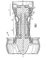
- a gas turbine engine 10 such as a turbofan gas turbine engine, circumferentially disposed about an engine centerline, or axial centerline axis 12 is shown in Figure 1 .
- the engine 10 includes a fan 14, a compressor 16, a combustion section 18 and a turbine 20.
- air compressed in the compressor 16 is mixed with fuel and burned in the combustion section 18 and expanded in turbine 20.
- the turbine 20 includes rotors 22 which rotate in response to the expansion, driving the compressor 16 and fan 14.
- the turbine 20 comprises alternating rows of rotary airfoils or blades 24 and static airfoils or vanes 26. In fact, this view is quite schematic, and blades 24 and vanes 26 are actually removable. It should be understood that this view is included simply to provide a basic understanding of the sections in a gas turbine engine, and not to limit the invention. This invention extends to all types of turbine engines for all types of applications.
- FIG. 2 is an enlarged view of turbine blades 24, and intermediate stationary vanes 26.
- sealing surfaces 34 are associated with knife edge seals 36.
- these knife edge seals extend at an angle relative to the axial centerline 12 of the jet engine.
- the knife edge seals are associated with concave pockets 38, as will be explained in more detail below.
- a labyrinth seal was created by cylindrical sealing surfaces 49 and 51 spaced at different radial positions, and knife edge seals 50 spaced from the associated static sealing surfaces 51 and 49.
- an abradable sealing material may actually be positioned to allow the knife edge seal to wear the material and provide a close fit.
- a labyrinth leakage path 54 is presented to any fluid which may leak radially inwardly of the rotor.
- the labyrinth seal path does provide a good restriction to linkage fluid. However, it would be desirable to even further improve the resistance of this path.
- fluid can be forced into vortices 40 and 42 by angling the knife edge seals 36 relative to a central line of the gas turbine engine, and creating pockets 38 from radially inner walls 39 and a radially outer wall 34.
- a vortex 42 is created in the pocket 38, and the angled knife edge seal 36 creates yet another vortex 40.
- the combination of the vortices 40 and 42 present a great resistance to fluid leakage. This is particularly true when there are additional knife edge seals at different radial positions, and positioned along a path of the fluid flow, as shown in Figure 3B .
- the knife edge seals 36 are angled into the pockets 38.
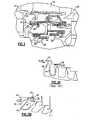
- the present invention thus provides a great resistance to leakage flow by utilizing angled knife edge seals and associated concave pockets. Possible arrangement of these two concepts are shown in Figures 4 and 5 . In Figures 4 and 5 it can be understood that fluid is flowing from the right to the left.
- Figure 4 shows an embodiment 80 wherein the knife edge seals 82 are angled along the path of the flow, and the pockets 84 face the path of the flow. This embodiment is particularly well suited when the static structure is in place and the rotating structure is moved from an aft location to a forward location for assembly.
- FIG. 5 An embodiment 90 is illustrated in Figure 5 .
- the knife edge seals 92 are angled along the path of flow, and the pockets 94 face away from the path of flow. This configuration is well-suited for when the rotating structure is in place and a static structure is moved from an aft location to a forward location.
- the present invention thus provides concave pockets formed of a radially inner surface spaced from a radially outer surface.
- the concave pockets create a vortex in the fluid flow which prevents leakage past the associated knife edge seal. Further, when the knife edge seals are angled, they create a second vortex further limiting leakage flow.
- the angle of the seals may range between 30 and 90° in example embodiments.
Landscapes
- Engineering & Computer Science (AREA)
- Mechanical Engineering (AREA)
- General Engineering & Computer Science (AREA)
- Turbine Rotor Nozzle Sealing (AREA)
- Sealing Using Fluids, Sealing Without Contact, And Removal Of Oil (AREA)
Claims (5)
- Turbinenabschnitt (20) für ein Gasturbinentriebwerk (10), umfassend:eine statische Struktur;wenigstens einen Rotor (22), der sich um eine Achse (12) dreht, wobei der Rotor (22) mit Rotorschaufeln (24) versehen ist und der Rotor (22) und die Rotorschaufeln (24) radial von der statischen Struktur beabstandet sind, wobei der Rotor (22) und die Rotorschaufeln (24) Messerkantendichtungen (36; 82; 92) aufweisen, die sich nah zu wenigstens einem Abschnitt der statischen Struktur erstrecken, um eine Dichtung bereitzustellen, und die statische Struktur konkave Taschen (38; 84; 94) aufweist, die wenigstens einer Mehrzahl der Messerkantendichtungen (36; 82; 92) zugeordnet sind, wobei die konkaven Taschen (38; 84; 94) durch eine radial innere Fläche (39) definiert sind, die von einer radial äußeren Fläche (34) beabstandet ist,dadurch gekennzeichnet, dass:die konkave Taschen (38; 84; 94) dazu konfiguriert sind, einen Wirbel im Fluidstrom zu erzeugen, der an einer zugeordneten Messerkantendichtung (36; 82; 92) vorbei gelangt; unddie Messerkantendichtungen (36; 82; 92) sich an einem nicht-senkrechten Winkel relativ zur Rotordrehachse (12) an einem Weg entlang erstrecken, der in Stromabwärtsrichtung verläuft.
- Gasturbinentriebwerk (10), umfassend:einen Kompressorabschnitt (16),einen Verbrennungsabschnitt (18); undeinen Turbinenabschnitt (20) nach einem der vorangehenden Ansprüche.
- Turbinenabschnitt (20) oder Triebwerk (10) nach Anspruch 1 oder 2, wobei wenigstens einige der konkaven Taschen (38; 84) in eine Stromaufwärtsrichtung oder zu dem Verbrennungsabschnitt (18) hin gewandt sind.
- Turbinenabschnitt (20) oder Triebwerk (10) nach Anspruch 1 oder 2, wobei wenigstens einige der konkaven Taschen (94) in eine Stromabwärtsrichtung oder von dem Verbrennungsabschnitt (18) fort gewandt sind.
- Turbinenabschnitt (20) oder Triebwerk (10) nach einem der vorangehenden Ansprüche, wobei eine Mehrzahl von Dichtungsflächen (34, 39) an der statischen Struktur in unterschiedlichen Abständen von der Achse (12) vorliegt und die Mehrzahl von Dichtungsflächen (34, 39) jeweils eine zugeordnete konkave Tasche (38; 84; 94) und eine zugeordnete Messerkantendichtung (36; 82; 92) aufweist.
Applications Claiming Priority (1)
| Application Number | Priority Date | Filing Date | Title |
|---|---|---|---|
| US11/605,678 US7708520B2 (en) | 2006-11-29 | 2006-11-29 | Gas turbine engine with concave pocket with knife edge seal |
Publications (3)
| Publication Number | Publication Date |
|---|---|
| EP1930551A2 EP1930551A2 (de) | 2008-06-11 |
| EP1930551A3 EP1930551A3 (de) | 2010-05-12 |
| EP1930551B1 true EP1930551B1 (de) | 2015-06-10 |
Family
ID=38983769
Family Applications (1)
| Application Number | Title | Priority Date | Filing Date |
|---|---|---|---|
| EP07254577.5A Active EP1930551B1 (de) | 2006-11-29 | 2007-11-26 | Turbinenstufe und entsprechendes Gasturbinentriebwerk |
Country Status (2)
| Country | Link |
|---|---|
| US (1) | US7708520B2 (de) |
| EP (1) | EP1930551B1 (de) |
Families Citing this family (25)
| Publication number | Priority date | Publication date | Assignee | Title |
|---|---|---|---|---|
| US8167547B2 (en) * | 2007-03-05 | 2012-05-01 | United Technologies Corporation | Gas turbine engine with canted pocket and canted knife edge seal |
| JP5484990B2 (ja) * | 2010-03-30 | 2014-05-07 | 三菱重工業株式会社 | タービン |
| US20110280715A1 (en) * | 2010-05-11 | 2011-11-17 | General Electric Company | Curved labyrinth seals |
| GB201013003D0 (en) | 2010-08-03 | 2010-09-15 | Rolls Royce Plc | A seal assembly |
| GB201013004D0 (en) | 2010-08-03 | 2010-09-15 | Rolls Royce Plc | A seal assembly |
| US20130004290A1 (en) * | 2011-06-29 | 2013-01-03 | General Electric Company | Turbo-Machinery With Flow Deflector System |
| US9097128B2 (en) * | 2012-02-28 | 2015-08-04 | General Electric Company | Seals for rotary devices and methods of producing the same |
| US9145786B2 (en) | 2012-04-17 | 2015-09-29 | General Electric Company | Method and apparatus for turbine clearance flow reduction |
| US9327368B2 (en) | 2012-09-27 | 2016-05-03 | United Technologies Corporation | Full ring inner air-seal with locking nut |
| JP5936515B2 (ja) * | 2012-10-18 | 2016-06-22 | 三菱日立パワーシステムズ株式会社 | 回転機械 |
| JP6078353B2 (ja) | 2013-01-23 | 2017-02-08 | 三菱日立パワーシステムズ株式会社 | ガスタービン |
| WO2014175936A2 (en) * | 2013-02-05 | 2014-10-30 | United Technologies Corporation | Gas turbine engine component having tip vortex creation feature |
| US20160305439A1 (en) * | 2013-12-13 | 2016-10-20 | United Technologies Corporation | Fan platform edge seal |
| FR3015591B1 (fr) * | 2013-12-19 | 2016-01-29 | Snecma | Virole de compresseur comprenant une lechette d'etancheite equipee d'une structure d'entrainement et de deviation d'air de fuite |
| JP6344735B2 (ja) | 2014-01-30 | 2018-06-20 | 三菱重工業株式会社 | シール構造、及び回転機械 |
| US9957826B2 (en) | 2014-06-09 | 2018-05-01 | United Technologies Corporation | Stiffness controlled abradeable seal system with max phase materials and methods of making same |
| DE102014224283A1 (de) * | 2014-11-27 | 2016-06-02 | Robert Bosch Gmbh | Verdichter mit einem Dichtkanal |
| FR3029960B1 (fr) * | 2014-12-11 | 2021-06-04 | Snecma | Roue a aubes avec joint radial pour une turbine de turbomachine |
| FR3029961B1 (fr) * | 2014-12-11 | 2021-06-11 | Snecma | Roue a aubes avec becquets pour une turbine de turbomachine |
| JP6209199B2 (ja) * | 2015-12-09 | 2017-10-04 | 三菱日立パワーシステムズ株式会社 | シールフィン,シール構造,ターボ機械及びシールフィンの製造方法 |
| JP6209200B2 (ja) * | 2015-12-09 | 2017-10-04 | 三菱日立パワーシステムズ株式会社 | ステップシール,シール構造,ターボ機械及びステップシールの製造方法 |
| JP2017145813A (ja) | 2016-02-19 | 2017-08-24 | 三菱日立パワーシステムズ株式会社 | 回転機械 |
| FR3055353B1 (fr) * | 2016-08-25 | 2018-09-21 | Safran Aircraft Engines | Ensemble formant joint d'etancheite a labyrinthe pour une turbomachine comportant un abradable et des lechettes inclines |
| US10408077B2 (en) * | 2017-01-26 | 2019-09-10 | United Tehnologies Corporation | Gas turbine seal |
| DE102018210513A1 (de) | 2018-06-27 | 2020-01-02 | MTU Aero Engines AG | Rotor für eine Strömungsmaschine und Strömungsmaschine mit einem solchen Rotor |
Family Cites Families (28)
| Publication number | Priority date | Publication date | Assignee | Title |
|---|---|---|---|---|
| GB190613004A (en) * | 1906-06-05 | 1907-02-14 | Wilhelm Heinrich Eyermann | Improvements in Stuffing Box Substitutes. |
| US1168002A (en) * | 1913-12-13 | 1916-01-11 | Norma Cie Ges Mit Beschraenkter Haftung | Packing for journals. |
| GB111897A (en) * | 1916-12-12 | 1917-12-12 | British Thomson Houston Co Ltd | Improvements in and relating to Shaft Packing Devices. |
| US1505647A (en) * | 1920-11-05 | 1924-08-19 | Gen Electric | Packing for elastic-fluid turbines and the like |
| US1482031A (en) * | 1923-01-18 | 1924-01-29 | Said Parsons | Packing for rotating bodies |
| US1708044A (en) * | 1923-09-12 | 1929-04-09 | Westinghouse Electric & Mfg Co | Labyrinth-gland packing |
| US1689735A (en) * | 1923-10-05 | 1928-10-30 | Losel Franz | Labyrinth gland construction |
| US1756958A (en) * | 1928-10-03 | 1930-05-06 | Westinghouse Electric & Mfg Co | Elastic-fluid turbine |
| BE533093A (de) * | 1953-11-12 | 1954-11-30 | ||
| GB804922A (en) * | 1956-01-13 | 1958-11-26 | Rolls Royce | Improvements in or relating to axial-flow fluid machines for example compressors andturbines |
| US3572728A (en) * | 1968-06-17 | 1971-03-30 | Gen Eelctric Co | Rotary seal |
| US3940153A (en) * | 1974-12-09 | 1976-02-24 | General Motors Corporation | Labyrinth seal |
| US4351532A (en) * | 1975-10-01 | 1982-09-28 | United Technologies Corporation | Labyrinth seal |
| US4477089A (en) * | 1982-07-26 | 1984-10-16 | Avco Corporation | Honeycomb seal for turbine engines |
| US4477088A (en) * | 1982-12-20 | 1984-10-16 | United Technologies Corporation | Face seal means with back-up seal |
| US5639095A (en) * | 1988-01-04 | 1997-06-17 | Twentieth Technology | Low-leakage and low-instability labyrinth seal |
| US5029876A (en) * | 1988-12-14 | 1991-07-09 | General Electric Company | Labyrinth seal system |
| US5161943A (en) * | 1991-03-11 | 1992-11-10 | Dresser-Rand Company, A General Partnership | Swirl control labyrinth seal |
| US5224713A (en) * | 1991-08-28 | 1993-07-06 | General Electric Company | Labyrinth seal with recirculating means for reducing or eliminating parasitic leakage through the seal |
| US5211535A (en) * | 1991-12-30 | 1993-05-18 | General Electric Company | Labyrinth seals for gas turbine engine |
| US5639211A (en) * | 1995-11-30 | 1997-06-17 | United Technology Corporation | Brush seal for stator of a gas turbine engine case |
| US5630590A (en) * | 1996-03-26 | 1997-05-20 | United Technologies Corporation | Method and apparatus for improving the airsealing effectiveness in a turbine engine |
| EP0903468B1 (de) * | 1997-09-19 | 2003-08-20 | ALSTOM (Switzerland) Ltd | Vorrichtung zur Spaltdichtung |
| US6000701A (en) * | 1997-12-15 | 1999-12-14 | Dresser-Rand Company | Labyrinth seal assembly and method |
| DE59709283D1 (de) * | 1997-12-23 | 2003-03-13 | Abb Turbo Systems Ag Baden | Verfahren und Vorrichtung zum berührungsfreien Abdichten eines zwischen einem Rotor und einem Stator ausgebildeten Trennspalts |
| EP1001139B1 (de) * | 1998-11-10 | 2004-01-07 | ALSTOM (Switzerland) Ltd | Spitzendichtung für Turbinenlaufschaufeln |
| US7334983B2 (en) * | 2005-10-27 | 2008-02-26 | United Technologies Corporation | Integrated bladed fluid seal |
| US7445213B1 (en) * | 2006-06-14 | 2008-11-04 | Florida Turbine Technologies, Inc. | Stepped labyrinth seal |
-
2006
- 2006-11-29 US US11/605,678 patent/US7708520B2/en active Active
-
2007
- 2007-11-26 EP EP07254577.5A patent/EP1930551B1/de active Active
Also Published As
| Publication number | Publication date |
|---|---|
| US7708520B2 (en) | 2010-05-04 |
| EP1930551A3 (de) | 2010-05-12 |
| US20080124215A1 (en) | 2008-05-29 |
| EP1930551A2 (de) | 2008-06-11 |
Similar Documents
| Publication | Publication Date | Title |
|---|---|---|
| EP1930551B1 (de) | Turbinenstufe und entsprechendes Gasturbinentriebwerk | |
| EP1967700B1 (de) | Gasturbinentriebwerk mit einer Labyrinthdichtung mit geneigten Aussparungen und Lamellen | |
| CN101858230B (zh) | 关于用于涡轮发动机的密封部的方法、系统和/或装置 | |
| EP3290646B1 (de) | Schwimmende, kontaktfreie dichtung mit gewinkelten trägern für eine verwendung in luftfahrtantriebe | |
| EP2659112B1 (de) | Gasturbinenmotor und schaufelsystem mit veränderbarer wölbung | |
| US20100247293A1 (en) | Variable area turbine vane arrangement | |
| CN108930594B (zh) | 交叉涡轮发动机的空气轴承和热管理喷嘴布置 | |
| EP1577504A1 (de) | Lagerdichtung mit einer Sicherungsvorrichtung | |
| CN109519224B (zh) | 包括涡轮转子组件的燃气涡轮发动机 | |
| EP2832975B1 (de) | Leitschaufelreihe, turbine und gasturbine | |
| EP2978938B1 (de) | Turbinenanordnung mit l-förmiger federdichtung | |
| EP1510655B1 (de) | Unterstützung einer Bürstendichtung | |
| CN103216277A (zh) | 可翻新的级间成角密封件 | |
| EP1574671B1 (de) | Turbinenmotor | |
| CN109505662B (zh) | 具有成角的内带凸缘的涡轮喷嘴 | |
| EP3323979B1 (de) | Schaufel mit platte mit umlaufender dichtung | |
| EP2636852B1 (de) | Innere Hybridluftdichtung für Gasturbinenmotoren | |
| EP3008309B1 (de) | Flusssteuerungsvorrichtung für einen gasturbinenmotor | |
| EP3822459B1 (de) | Deckbandsegment mit kühlungsnut | |
| US20160123169A1 (en) | Methods and system for fluidic sealing in gas turbine engines | |
| EP3712395B1 (de) | Dichtungsanordnung für einen gasturbinenmotor | |
| EP3052766B1 (de) | Schaufeldichtungssystem und dichtung dafür | |
| EP3839218B1 (de) | Verbesserte rotorschaufeldichtungsstrukturen | |
| US9771817B2 (en) | Methods and system for fluidic sealing in gas turbine engines | |
| GB2452297A (en) | Compressor leakage flow control |
Legal Events
| Date | Code | Title | Description |
|---|---|---|---|
| PUAI | Public reference made under article 153(3) epc to a published international application that has entered the european phase |
Free format text: ORIGINAL CODE: 0009012 |
|
| AK | Designated contracting states |
Kind code of ref document: A2 Designated state(s): AT BE BG CH CY CZ DE DK EE ES FI FR GB GR HU IE IS IT LI LT LU LV MC MT NL PL PT RO SE SI SK TR |
|
| AX | Request for extension of the european patent |
Extension state: AL BA HR MK RS |
|
| PUAL | Search report despatched |
Free format text: ORIGINAL CODE: 0009013 |
|
| AK | Designated contracting states |
Kind code of ref document: A3 Designated state(s): AT BE BG CH CY CZ DE DK EE ES FI FR GB GR HU IE IS IT LI LT LU LV MC MT NL PL PT RO SE SI SK TR |
|
| AX | Request for extension of the european patent |
Extension state: AL BA HR MK RS |
|
| RIC1 | Information provided on ipc code assigned before grant |
Ipc: F01D 11/02 20060101ALI20100407BHEP Ipc: F01D 11/00 20060101AFI20080211BHEP |
|
| 17P | Request for examination filed |
Effective date: 20101110 |
|
| 17Q | First examination report despatched |
Effective date: 20101214 |
|
| AKX | Designation fees paid |
Designated state(s): DE GB |
|
| GRAP | Despatch of communication of intention to grant a patent |
Free format text: ORIGINAL CODE: EPIDOSNIGR1 |
|
| INTG | Intention to grant announced |
Effective date: 20150224 |
|
| GRAS | Grant fee paid |
Free format text: ORIGINAL CODE: EPIDOSNIGR3 |
|
| GRAA | (expected) grant |
Free format text: ORIGINAL CODE: 0009210 |
|
| AK | Designated contracting states |
Kind code of ref document: B1 Designated state(s): DE GB |
|
| REG | Reference to a national code |
Ref country code: GB Ref legal event code: FG4D |
|
| REG | Reference to a national code |
Ref country code: DE Ref legal event code: R096 Ref document number: 602007041728 Country of ref document: DE |
|
| REG | Reference to a national code |
Ref country code: DE Ref legal event code: R097 Ref document number: 602007041728 Country of ref document: DE |
|
| PLBE | No opposition filed within time limit |
Free format text: ORIGINAL CODE: 0009261 |
|
| STAA | Information on the status of an ep patent application or granted ep patent |
Free format text: STATUS: NO OPPOSITION FILED WITHIN TIME LIMIT |
|
| 26N | No opposition filed |
Effective date: 20160311 |
|
| REG | Reference to a national code |
Ref country code: DE Ref legal event code: R082 Ref document number: 602007041728 Country of ref document: DE Representative=s name: SCHMITT-NILSON SCHRAUD WAIBEL WOHLFROM PATENTA, DE |
|
| REG | Reference to a national code |
Ref country code: DE Ref legal event code: R082 Ref document number: 602007041728 Country of ref document: DE Representative=s name: SCHMITT-NILSON SCHRAUD WAIBEL WOHLFROM PATENTA, DE Ref country code: DE Ref legal event code: R081 Ref document number: 602007041728 Country of ref document: DE Owner name: UNITED TECHNOLOGIES CORP. (N.D.GES.D. STAATES , US Free format text: FORMER OWNER: UNITED TECHNOLOGIES CORP., HARTFORD, CONN., US |
|
| PGFP | Annual fee paid to national office [announced via postgrant information from national office to epo] |
Ref country code: DE Payment date: 20211020 Year of fee payment: 15 |
|
| REG | Reference to a national code |
Ref country code: DE Ref legal event code: R081 Ref document number: 602007041728 Country of ref document: DE Owner name: RAYTHEON TECHNOLOGIES CORPORATION (N.D.GES.D.S, US Free format text: FORMER OWNER: UNITED TECHNOLOGIES CORP. (N.D.GES.D. STAATES DELAWARE), FARMINGTON, CONN., US |
|
| REG | Reference to a national code |
Ref country code: DE Ref legal event code: R119 Ref document number: 602007041728 Country of ref document: DE |
|
| PG25 | Lapsed in a contracting state [announced via postgrant information from national office to epo] |
Ref country code: DE Free format text: LAPSE BECAUSE OF NON-PAYMENT OF DUE FEES Effective date: 20230601 |
|
| PGFP | Annual fee paid to national office [announced via postgrant information from national office to epo] |
Ref country code: GB Payment date: 20231019 Year of fee payment: 17 |