EP1930277A1 - Control device for elevator - Google Patents
Control device for elevator Download PDFInfo
- Publication number
- EP1930277A1 EP1930277A1 EP05788106A EP05788106A EP1930277A1 EP 1930277 A1 EP1930277 A1 EP 1930277A1 EP 05788106 A EP05788106 A EP 05788106A EP 05788106 A EP05788106 A EP 05788106A EP 1930277 A1 EP1930277 A1 EP 1930277A1
- Authority
- EP
- European Patent Office
- Prior art keywords
- car
- slowdown
- speed
- stopping distance
- next stop
- Prior art date
- Legal status (The legal status is an assumption and is not a legal conclusion. Google has not performed a legal analysis and makes no representation as to the accuracy of the status listed.)
- Withdrawn
Links
Images


Classifications
-
- B—PERFORMING OPERATIONS; TRANSPORTING
- B66—HOISTING; LIFTING; HAULING
- B66B—ELEVATORS; ESCALATORS OR MOVING WALKWAYS
- B66B1/00—Control systems of elevators in general
- B66B1/24—Control systems with regulation, i.e. with retroactive action, for influencing travelling speed, acceleration, or deceleration
- B66B1/28—Control systems with regulation, i.e. with retroactive action, for influencing travelling speed, acceleration, or deceleration electrical
- B66B1/30—Control systems with regulation, i.e. with retroactive action, for influencing travelling speed, acceleration, or deceleration electrical effective on driving gear, e.g. acting on power electronics, on inverter or rectifier controlled motor
-
- B—PERFORMING OPERATIONS; TRANSPORTING
- B66—HOISTING; LIFTING; HAULING
- B66B—ELEVATORS; ESCALATORS OR MOVING WALKWAYS
- B66B1/00—Control systems of elevators in general
- B66B1/24—Control systems with regulation, i.e. with retroactive action, for influencing travelling speed, acceleration, or deceleration
-
- B—PERFORMING OPERATIONS; TRANSPORTING
- B66—HOISTING; LIFTING; HAULING
- B66B—ELEVATORS; ESCALATORS OR MOVING WALKWAYS
- B66B1/00—Control systems of elevators in general
- B66B1/02—Control systems without regulation, i.e. without retroactive action
- B66B1/06—Control systems without regulation, i.e. without retroactive action electric
- B66B1/14—Control systems without regulation, i.e. without retroactive action electric with devices, e.g. push-buttons, for indirect control of movements
-
- B—PERFORMING OPERATIONS; TRANSPORTING
- B66—HOISTING; LIFTING; HAULING
- B66B—ELEVATORS; ESCALATORS OR MOVING WALKWAYS
- B66B1/00—Control systems of elevators in general
- B66B1/24—Control systems with regulation, i.e. with retroactive action, for influencing travelling speed, acceleration, or deceleration
- B66B1/28—Control systems with regulation, i.e. with retroactive action, for influencing travelling speed, acceleration, or deceleration electrical
- B66B1/285—Control systems with regulation, i.e. with retroactive action, for influencing travelling speed, acceleration, or deceleration electrical with the use of a speed pattern generator
Definitions
- the present invention relates to a control device for an elevator, which controls a speed of a car in accordance with, for example, a load within the car or the like.
- a conventional speed control device for an elevator which is structured to calculate a position at which a car can land as a position preceding a current position of the car and control the speed of the car in accordance with the position at which the car can land, has been proposed.
- a destination floor is registered in response to a call for the car, and it is determined whether or not the car can land at the registered destination floor.
- a speed pattern corresponding to the current position of the car and the destination floor is generated regardless of a load within the car.
- the speed of the car is controlled in accordance with the generated speed pattern (see Patent Document 1).
- Patent Document 1 JP 04-20469 A
- the conventional speed control device cannot calculate a position at which the car can land as to each of all speed patterns.
- the present invention has been made to solve the above-mentioned problem, and it is therefore an object of the present invention to obtain a control device for an elevator which makes it possible to move a car more efficiently and determine more accurately whether or not the car can be normally stopped at a destination floor registered in response to a call for the car.
- a control device for an elevator includes: next stop floor setting means for setting a next stop floor at which a car is to be stopped next, based on a registration of a call for the car; a speed controller for calculating a maximum speed, an acceleration, and a jerk based on information from a weighing device for detecting a load within the car and information from the next stop floor setting means, generating a speed pattern to a time point when the car is normally stopped at the next stop floor based on the calculated maximum speed, the calculated acceleration, and the calculated jerk, and controlling a speed of the car according to the speed pattern; slowdown stopping distance calculating means for calculating a slowdown stopping distance in normally stopping the car from a current position of the car, based on information from the speed controller; and advance position calculating means for calculating an advance position through addition of the slowdown stopping distance to the current position of the car.
- the next stop floor setting means compares a position of a destination floor registered in response to the call for the car with the advance position to set the next
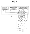
- Fig. 1 is a typical block diagram showing an elevator according to Embodiment 1 of the present invention.
- a car 2 and a counterweight 3 are provided within a hoistway 1 in a manner allowing the car 2 and the counterweight 3 to be raised/lowered.
- a hoisting machine (drive device) 4 for raising/lowering the car 2 and the counterweight 3 is provided in an upper portion of the hoistway 1.
- the hoisting machine 4 has a hoisting machine body 5 including a motor, and a drive sheave 6 that is rotated by the hoisting machine body 5.
- a plurality of main ropes 7 are looped around the drive sheave 6.
- the car 2 and the counterweight 3 are suspended within the hoistway 1 by means of the respective main ropes 7.
- the car 2 and the counterweight 3 are raised/lowered within the hoistway 1 through rotation of the drive sheave 6.
- the hoisting machine body 5 is provided with an encoder (detector) 8 for generating a signal corresponding to rotation of the drive sheave 6.
- the car 2 is provided with a weighing device 9 for detecting a weight within the car 2 as a load. Information from the encoder 8 and information from the weighing device 9 are transmitted to a control device 10 for the elevator.
- the control device 10 has a speed controller 11 for controlling the speed of the car 2 through control of the driving of the hoisting machine 4, slowdown stopping distance calculating means 12 for calculating, based on information from the speed controller 11, a slowdown stopping distance covered in stopping the car 2 from a current position SYNC thereof through a slowdown operation of the motor of the hoisting machine body 5 (i.e., in stopping car 2 normally), advance position calculating means 13 for calculating a slowdown stop position (advance position ADVN) of the car 2 through addition of the slowdown stopping distance calculated by the slowdown stopping distance calculating means 12 to the current position SYNC of the car 2, and next stop floor setting means 14 for setting, based on information from the advance position calculating means 13 and information on registrations of calls for the car 2, a next stop floor at which the car 2 is to be stopped next.
- speed controller 11 for controlling the speed of the car 2 through control of the driving of the hoisting machine 4
- slowdown stopping distance calculating means 12 for calculating, based on information from the
- the control device 10 is constituted by a computer having a calculation processing portion (CPU), a storage portion (ROM, RAM, and the like), and signal input/output portions.
- the functions of the speed controller 11, the slowdown stopping distance calculating means 12, the advance position calculating means 13, and the next stop floor setting means 14 are realized by the computer constituting the control device 10.
- programs for realizing the functions of the speed controller 11, the slowdown stopping distance calculating means 12, the advance position calculating means 13, and the next stop floor setting means 14 are stored in the storage portion of the computer.
- Data on arithmetic expressions and information on the encoder 8, the weighing device 9, and the like are also stored in the storage portion.
- the calculation processing portion performs calculation processings regarding the functions of the control device 10 based on the programs stored in the storage portion.
- the speed controller 11 generates as a speed pattern time-dependent changes in the speed of the car 2 to a time point when the car 2 is normally stopped at the next stop floor, based on information from the weighing device 9 and information from the next stop floor setting means 14. That is, the speed controller 11 calculates a maximum speed, an acceleration, and a jerk based on a load within the car 2 and a position of the next stop floor, and generates a speed pattern of the car 2 based on the calculated maximum speed, the calculated acceleration, and the calculated jerk. Further, the speed controller 11 detects a speed of the car 2 based on information from the encoder 8, and controls the hoisting machine body 5 via an inverter 15 such that the detected speed of the car 2 follows the speed pattern.
- the slowdown stopping distance calculating means 12 and the advance position calculating means 13 constantly calculate a slowdown stopping distance and an advance position respectively on a certain calculation cycle.
- the next stop floor settingmeans 14 compares the advance position ADVN of the car 2, which has been calculated by the advance position calculating means 13, with a position of a destination floor registered in response to each call for the car 2, thereby setting a next stop floor of the car 2. That is, the next stop floor setting means 14 refrains from regarding the destination floor as the next stop floor when the advance position ADVN of the car 2 is farther ahead of a current position of the car 2 than the destination floor, and regards the destination floor as a candidate for the next stop floor when the advance position ADVN of the car 2 is at the same position as the destination floor or short of the destination floor with respect to the car 2. Among a plurality of destination floors as candidates for the next stop floor, the destination floor closest to the car 2 is set as the next stop floor.
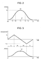
- Fig. 2 is a graph showing an example of a speed pattern of the car 2 generated by the speed controller 11 of Fig. 1 .
- the speed pattern generated by the speed controller 11 is set such that the speed of the car 2 reaches a maximum speed V0 at a time point T3 between a time point when the car 2 starts to be moved and a time point when the car 2 is normally stopped. That is, the speed pattern is set such that the car 2 is sped up from the time point when the car 2 starts to be moved to the time point T3, and that the car 2 is slowed down from the time point T3 to the time point when the car 2 is normally stopped.
- a starting jerk time period in which the car 2 increases in acceleration with the lapse of time, a constant acceleration time period in which the car 2 is at a constant acceleration, and an acceleration round-off time period in which the car 2 decreases in acceleration with the lapse of time are set.
- a time point corresponding to a shift from the starting jerk time period to the constant acceleration time period is denoted by T1
- a time point corresponding to a shift from the constant acceleration time period to the acceleration round-off time period is denoted by T2 (T2 > T1).
- a deceleration round-off time period in which the car 2 increases in acceleration in the direction opposite to the moving direction thereof (i.e., deceleration) with the lapse of time a constant deceleration time period in which the car 2 is at a constant deceleration, and a landing jerk time period in which the car 2 decreases in deceleration with the lapse of time are set between the time point T3 and the time point when the car 2 is normally stopped.
- T4 A time point corresponding to a shift from the deceleration round-off time period to the constant deceleration time period is denoted by T4, and a time point corresponding to a shift from the constant deceleration time period to the landing jerk time period is denoted by T5 (T5 > T4).
- a distance that is covered from the time point when the car 2 starts to be moved to the time point when the car 2 is normally stopped is expressed as an area of a region surrounded by a curve Q2-K2-L2 and a line Q2-L2 of Fig. 2 .
- the next stop floor setting means 14 sets an appropriate one of destination floors registered in response to the calls for the car 2, namely, the destination floor closest to the car 2 as a next stop floor.
- the speed controller 11 generates a speed pattern of the car 2 from a time point when the car 2 starts to be moved from a current position thereof to a time point when the car 2 is normally stopped at the next stop floor.
- the speed pattern thus generated conforms to a load within the car 2 at the time point when the car 2 starts to be moved.
- the speed controller 11 constantly detects the speed of the car 2 based on information from the encoder 8, and controls the rotational speed of the drive sheave 6 such that the speed of the car 2 follows the speed pattern.
- a slowdown stopping distance and an advance position are calculated in an appropriate one of four different calculation modes MOD (modes 1 to 4) set according to time zones in the speed pattern respectively, namely, that one of the calculation modes MOD which corresponds to a time point when the call for the car 2 is registered.
- the slowdown stopping distance and the advance position are calculated through an arithmetic operation in the mode 1 when the call for the car 2 is registered before the time point T1 (within the starting jerk time period), through an arithmetic operation in the mode 2 when the call for the car 2 is registered between the time point T1 and the time point T2 (within the constant acceleration time period), through an arithmetic operation in the mode 3 when the call for the car 2 is registered between the time point T2 and the time point T3 (within the acceleration round-off time period), and through an arithmetic operation in the mode 4 when the call for the car 2 is registered between the time point T3 and the time point when the car 2 is normally stopped.
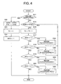
- Fig. 3 is a graph showing time-dependent changes in the speed and acceleration of the car 2 for calculating a slowdown stopping distance of the car 2 when a call for the car 2 is registered before the time point T1 of Fig. 2 .
- a call for the car 2 is registered within, for example, a starting jerk time period Tj
- a direct shift to an acceleration round-off time period Ta is made after the lapse of the starting jerk time period Tj
- a direct shift to a landing jerk time period Tl is made after the lapse of a deceleration round-off time period Td.
- the slowdown stopping distance of the car 2 is expressed as an area of a region surrounded by a curve J1-K1-Q1 and a line J1-Q1. That is, the arithmetic operation in the mode 1 means an arithmetic operation of calculating an area of the region surrounded by the curve J1-K1-Q1 and the line J1-Q1 of Fig. 3 to calculate a slowdown stopping distance and adding the slowdown stopping distance to a current position of the car 2 to calculate an advance position.
- the acceleration of the car 2 at the beginning of the acceleration round-off time period Ta is denoted by ⁇ a
- the acceleration of the car 2 at the end of the deceleration round-off time period Td is denoted by ⁇ d.
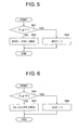
- Fig. 4 is a flowchart showing the arithmetic operation of the control device 10 of Fig. 1 .
- the arithmetic operation of the control device 10 is constantly performed on a certain cycle.
- the speed controller 11 first determines whether or not the car 2 remains stopped (S11).
- the current position SYNC of the car 2 is set as an initial value for each of a start position STAT at which the car 2 starts to be moved and the advance position ADVN (S12).
- 0 is set as an initial value for a counter TC (S13)
- the mode 1 is set as an initial value for the calculation mode MOD for calculating the advance position ADVN (S14). After that, a calculation in the mode 1 is performed to terminate the arithmetic operation.
- the next stop floor setting means 14 determines whether or not the coordinate of the advance position ADVN is equal to or larger than the coordinate of a position STOP of a destination floor registered in response to a call for the car 2 (S15).
- the coordinate of the advance position ADVN is larger than the coordinate of the position STOP of the destination floor, the car 2 cannot be stopped at the position STOP of the destination floor, so the arithmetic operation is terminated.
- the next stop floor setting means 14 adds 1 to the counter TC (S16). After that, the speed controller 11 determines whether or not the calculation mode MOD is the mode 1 (S17). When the calculation mode MOD is the mode 1, the calculation in the mode 1 is performed (S30) to terminate the arithmetic operation.
- the speed controller 11 determines whether or not the calculation mode MOD is the mode 2 (S18).
- the calculation mode MOD is the mode 2
- a calculation in the mode 2 is performed (S40) to terminate the arithmetic operation.
- the speed controller 11 determines whether or not the calculation mode MOD is the mode 3 (S19). When the calculation mode MOD is the mode 3, a calculation in the mode 3 is performed (S50) to terminate the arithmetic operation.
- the speed controller 11 determines whether or not the calculation mode MOD is the mode 4 (S20). When the calculation mode MOD is the mode 4, a calculation in the mode 4 is performed (S60) to terminate the arithmetic operation. When the calculation mode MOD is not the mode 4, the arithmetic operation is terminated immediately.
- Fig. 5 is a flowchart showing the arithmetic operation (S30) according to the mode 1 of Fig. 4 .
- it is first determined whether or not the value indicating the time point of the counter TC is equal to or larger than the value indicating the time point T1 (S31).
- the value indicating the time point of the counter TC is smaller than the value indicating the time point T1
- a distance BIAS that is covered from the time point when the car 2 starts to be moved to the time point when the car 2 is normally stopped is expressed as the area of the region surrounded by the curve J1-K1-Q1 and the line J1-Q1.
- the distance BIAS is calculated according to a formula (1).
- the advance position ADVN is calculated according to a formula (2) (S32) using the distance BIAS calculated according to the formula (1) and the start position STAT of the car 2, so the arithmetic operation is terminated.
- ADVN STAT + BIAS
- the calculation mode MOD is set to the mode 2 (S33) to terminate the arithmetic operation.
- Fig. 6 is a flowchart showing the arithmetic operation (S40) according to the mode 2 of Fig. 4 .
- S40 the arithmetic operation
- the time point of the counter TC belongs to the constant acceleration time period of Fig. 2 (from time point T1 to time point T2). Therefore, given that V denotes the speed of the car 2 at the time point of the counter TC, the advance position ADVN is calculated according to a formula (3) (S42).
- ADVN V + 1 / 2 ⁇ ⁇ a ⁇ Ta ⁇ Ta + Td + ( 1 / 6 ) ( - ⁇ a ⁇ Ta 2 + ⁇ d ⁇ td 2 + ⁇ d ⁇ tl 2 ) + ( 1 / 2 ) ⁇ d ( V + 1 / 2 ⁇ ⁇ a ⁇ Ta - ( 1 / 2 ) ⁇ d ⁇ Td - ( 1 / 2 ) ⁇ d ⁇ Tl ) + 1 / 2 ⁇ T ⁇ 1 ( V + 1 / 2 ⁇ ⁇ a ⁇ Ta - ( 1 / 2 ) ⁇ d ⁇ Td - ( 1 / 2 ) ⁇ d ⁇ Tl )
- the calculation mode MOD is set to the mode 3 (S43) to terminate the arithmetic operation.
- Fig. 7 is a flowchart showing the arithmetic operation (S50) according to the mode 3 of Fig. 4 .
- S50 the arithmetic operation
- the time point of the counter TC belongs to the acceleration round-off time period (from time point T2 to time point T3) of Fig. 2 . Therefore, the speed of the car 2 always follows the speed pattern of Fig. 2 .
- the distance that is covered from the time point when the car 2 starts to be moved from the start position STAT to the time point when the car 2 is normally stopped is always expressed by the area of the region surrounded by the curve Q2-K2-L2 and the line Q2-L2 of Fig. 2 .
- the advance position ADVN is held at a position corresponding to the end of the constant acceleration time period (time point T2) and remains unchanged with the lapse of time.
- the calculation mode MOD is set to the mode 4 (S52) to terminate the arithmetic operation.
- Fig. 8 is a flowchart showing the arithmetic operation (S60) according to the mode 4 of Fig. 4 .
- the time point of the counter TC is either a time point when the car 2 is moved at the maximum speed (rated speed) V0 or a time point when the car 2 is slowed down.
- a slowdown stopping distance DSLR in this case is constantly expressed as an area of a region surrounded by a line J2-K2, a curve K2-L2, and a line L2-J2 of Fig. 2 .
- the slowdown stopping distance DSLR is calculated according to a formula (4).
- t denotes the constant deceleration time period from the time point T4 to the time point T5.
- the advance position ADVN is calculated from a formula (5), using the current position SYNC of the car 2 and the slowdown stopping distance DSLR.
- the advance position ADVN is calculated according to the formula (5) (S61) to terminate the arithmetic operation.
- Fig. 9 is a graph showing time-dependent changes in the current position SYNC and the advance position ADVN of the car 2, which are calculated through the arithmetic operations of Fig. 4 .
- the advance position ADVN is constant when the time point of the counter TC belongs to the starting jerk time period (from time point when car 2 starts to be moved to time point T1) or the acceleration round-off time period (from time point T2 to time point T3).
- the slowdown stopping distance DSLR between the advance position ADVN and the current position SYNC of the car 2 increases with the lapse of time when the time point of the counter TC belongs to the constant acceleration time period (from time point T1 to time point T2).
- the slowdown stopping distance DSLR between the advance position ADVN and the current position SYNC of the car 2 is constant when the time point of the counter TC belongs to the time period from the end of the acceleration round-off time period to the time point when the car 2 is normally stopped.
- the speed controller 11 calculates a maximum speed, an acceleration, and a jerk based on a load within the car 2 and a position of a next stop floor, and generates a speed pattern of the car 2 based on the calculated maximum speed, the calculated acceleration, and the calculated jerk.
- the advance position calculating means 13 adds a slowdown stopping distance of the car 2 to a current position of the car 2 to calculate the advance position ADVN.
- the next stop floor setting means 14 compares a position of a destination floor registered in response to each call for the car 2 with the advance position ADVN of the car 2 to set a next stop floor.
- the slowdown stopping distance calculating means 12 may set as an initial value a slowdown stopping distance corresponding to at least one of a load within the car 2 and a position of a next stop floor. With this structure, it is possible to move the car 2 efficiently. Even in the case where the speed pattern of the car 2 has been changed, it is possible to calculate a slowdown stopping distance corresponding to the changed speed pattern.
- the slowdown stopping distance calculating means 12 may calculate a slowdown stopping distance from a minimum deceleration set in the speed controller 11, and set the calculated slowdown stopping distance as an initial value (minimum value).
- the initial value of the slowdown stopping distance is set when the car 2 starts to be moved.
- the slowdown stopping distance calculating means 12 may calculate a slowdown stopping distance of the car 2 based on information from a current detector for measuring a current (motor current) supplied to the motor of the hoisting machine body 5. Alternatively, the slowdown stopping distance calculating means 12 may calculate a slowdown stopping distance of the car 2 based on information from a torque command device for generating a torque command for the motor. With those structures, it is possible to calculate a slowdown stopping distance of the car 2 more accurately and determine more accurately whether or not the car 2 can be normally stopped at a destination floor registered in response to each call for the car 2.
- the slowdown stopping distance calculating means 12 calculates a slowdown stopping distance of the car 2 from a deceleration that is set such that the speed of the car 2 becomes lower than the overspeed detectionlevel.
- a brake device mounted on the hoisting machine 4 is operated to brake rotation of the drive sheave 6, so the movement of the car 2 is forcibly braked.
Landscapes
- Engineering & Computer Science (AREA)
- Automation & Control Theory (AREA)
- Elevator Control (AREA)
Abstract
A control device for an elevator has a speed controller for controlling a speed of a car, slowdown stopping distance calculating means for calculating a slowdown stopping distance in normally stopping the car from a current position thereof based on information from the speed controller, advance position calculating means for calculating an advance position through addition of the slowdown stopping distance calculated by the slowdown stopping distance calculating means to the current position of the car, and next stop floor setting means for setting a next stop floor at which the car is to be stopped next through comparison of a position of a destination floor registered in response to each call for the car with the advance position. The speed controller calculates a maximum speed, an acceleration, and a jerk based on information from a weighing device and information from the next stop floor setting means, generates a speed pattern to a time point when the car is normally stopped at the next stop floor based on the calculated maximum speed, the calculated acceleration, and the calculated jerk, and controls the speed of the car according to the speed pattern.
Description
- The present invention relates to a control device for an elevator, which controls a speed of a car in accordance with, for example, a load within the car or the like.
- A conventional speed control device for an elevator, which is structured to calculate a position at which a car can land as a position preceding a current position of the car and control the speed of the car in accordance with the position at which the car can land, has been proposed. In the conventional speed control device thus structured, a destination floor is registered in response to a call for the car, and it is determined whether or not the car can land at the registered destination floor. When it is determined that the car can land at the destination floor, a speed pattern corresponding to the current position of the car and the destination floor is generated regardless of a load within the car. The speed of the car is controlled in accordance with the generated speed pattern (see Patent Document 1).
- Patent Document 1:
JP 04-20469 A - However, in a case where the speed pattern is generated differently in accordance with the load within the car as well with a view to improving efficiency in moving the car, at least one of a maximum speed of the car, an acceleration of the car, and a jerk of the car is changed when the load within the car has changed due to passengers getting on and off. Accordingly, the conventional speed control device cannot calculate a position at which the car can land as to each of all speed patterns.
- The present invention has been made to solve the above-mentioned problem, and it is therefore an object of the present invention to obtain a control device for an elevator which makes it possible to move a car more efficiently and determine more accurately whether or not the car can be normally stopped at a destination floor registered in response to a call for the car.
- A control device for an elevator according to the present invention includes: next stop floor setting means for setting a next stop floor at which a car is to be stopped next, based on a registration of a call for the car; a speed controller for calculating a maximum speed, an acceleration, and a jerk based on information from a weighing device for detecting a load within the car and information from the next stop floor setting means, generating a speed pattern to a time point when the car is normally stopped at the next stop floor based on the calculated maximum speed, the calculated acceleration, and the calculated jerk, and controlling a speed of the car according to the speed pattern; slowdown stopping distance calculating means for calculating a slowdown stopping distance in normally stopping the car from a current position of the car, based on information from the speed controller; and advance position calculating means for calculating an advance position through addition of the slowdown stopping distance to the current position of the car. The next stop floor setting means compares a position of a destination floor registered in response to the call for the car with the advance position to set the next stop floor.
-
-
Fig. 1 is a typical block diagram showing an elevator according toEmbodiment 1 of the present invention. -
Fig. 2 is a graph showing an example of a speed pattern of the car generated by the speed controller ofFig. 1 . -
Fig. 3 is a graph showing time-dependent changes in the speed and acceleration of the car for calculating a slowdown stopping distance of the car when a call for the car is registered before the time point T1 ofFig. 2 . -
Fig. 4 is a flowchart showing the arithmetic operation of the control device ofFig. 1 . -
Fig. 5 is a flowchart showing the arithmetic operation according to themode 1 ofFig. 4 . -
Fig. 6 is a flowchart showing the arithmetic operation according to themode 2 ofFig. 4 . -
Fig. 7 is a flowchart showing the arithmetic operation according to themode 3 ofFig. 4 . -
Fig. 8 is a flowchart showing the arithmetic operation according to themode 4 ofFig. 4 . -
Fig. 9 is a graph showing time-dependent changes in the current position SYNC and the advance position ADVN of the car, which are calculated through the arithmetic operations ofFig. 4 . - A preferred embodiment of the present invention will be described hereinafter with reference to the drawings.
-
Fig. 1 is a typical block diagram showing an elevator according toEmbodiment 1 of the present invention. Referring toFig. 1 , acar 2 and acounterweight 3 are provided within ahoistway 1 in a manner allowing thecar 2 and thecounterweight 3 to be raised/lowered. A hoisting machine (drive device) 4 for raising/lowering thecar 2 and thecounterweight 3 is provided in an upper portion of thehoistway 1. The hoistingmachine 4 has a hoistingmachine body 5 including a motor, and adrive sheave 6 that is rotated by the hoistingmachine body 5. A plurality ofmain ropes 7 are looped around thedrive sheave 6. Thecar 2 and thecounterweight 3 are suspended within thehoistway 1 by means of the respectivemain ropes 7. Thecar 2 and thecounterweight 3 are raised/lowered within thehoistway 1 through rotation of thedrive sheave 6. - The hoisting
machine body 5 is provided with an encoder (detector) 8 for generating a signal corresponding to rotation of thedrive sheave 6. Thecar 2 is provided with a weighing device 9 for detecting a weight within thecar 2 as a load. Information from theencoder 8 and information from the weighing device 9 are transmitted to acontrol device 10 for the elevator. - The
control device 10 has aspeed controller 11 for controlling the speed of thecar 2 through control of the driving of the hoistingmachine 4, slowdown stopping distance calculatingmeans 12 for calculating, based on information from thespeed controller 11, a slowdown stopping distance covered in stopping thecar 2 from a current position SYNC thereof through a slowdown operation of the motor of the hoisting machine body 5 (i.e., in stoppingcar 2 normally), advance position calculatingmeans 13 for calculating a slowdown stop position (advance position ADVN) of thecar 2 through addition of the slowdown stopping distance calculated by the slowdown stopping distance calculatingmeans 12 to the current position SYNC of thecar 2, and next stop floor setting means 14 for setting, based on information from the advance position calculatingmeans 13 and information on registrations of calls for thecar 2, a next stop floor at which thecar 2 is to be stopped next. - The
control device 10 is constituted by a computer having a calculation processing portion (CPU), a storage portion (ROM, RAM, and the like), and signal input/output portions. The functions of thespeed controller 11, the slowdown stopping distance calculating means 12, the advance position calculating means 13, and the next stop floor setting means 14 are realized by the computer constituting thecontrol device 10. - That is, programs for realizing the functions of the
speed controller 11, the slowdown stopping distance calculating means 12, the advance position calculatingmeans 13, and the next stop floor setting means 14 are stored in the storage portion of the computer. Data on arithmetic expressions and information on theencoder 8, the weighing device 9, and the like are also stored in the storage portion. The calculation processing portion performs calculation processings regarding the functions of thecontrol device 10 based on the programs stored in the storage portion. - The
speed controller 11 generates as a speed pattern time-dependent changes in the speed of thecar 2 to a time point when thecar 2 is normally stopped at the next stop floor, based on information from the weighing device 9 and information from the next stop floor setting means 14. That is, thespeed controller 11 calculates a maximum speed, an acceleration, and a jerk based on a load within thecar 2 and a position of the next stop floor, and generates a speed pattern of thecar 2 based on the calculated maximum speed, the calculated acceleration, and the calculated jerk. Further, thespeed controller 11 detects a speed of thecar 2 based on information from theencoder 8, and controls the hoistingmachine body 5 via aninverter 15 such that the detected speed of thecar 2 follows the speed pattern. - The slowdown stopping distance calculating means 12 and the advance position calculating means 13 constantly calculate a slowdown stopping distance and an advance position respectively on a certain calculation cycle.
- The next
stop floor settingmeans 14 compares the advance position ADVN of thecar 2, which has been calculated by the advance position calculatingmeans 13, with a position of a destination floor registered in response to each call for thecar 2, thereby setting a next stop floor of thecar 2. That is, the next stop floor setting means 14 refrains from regarding the destination floor as the next stop floor when the advance position ADVN of thecar 2 is farther ahead of a current position of thecar 2 than the destination floor, and regards the destination floor as a candidate for the next stop floor when the advance position ADVN of thecar 2 is at the same position as the destination floor or short of the destination floor with respect to thecar 2. Among a plurality of destination floors as candidates for the next stop floor, the destination floor closest to thecar 2 is set as the next stop floor. -
Fig. 2 is a graph showing an example of a speed pattern of thecar 2 generated by thespeed controller 11 ofFig. 1 . As shown inFig. 2 , the speed pattern generated by thespeed controller 11 is set such that the speed of thecar 2 reaches a maximum speed V0 at a time point T3 between a time point when thecar 2 starts to be moved and a time point when thecar 2 is normally stopped. That is, the speed pattern is set such that thecar 2 is sped up from the time point when thecar 2 starts to be moved to the time point T3, and that thecar 2 is slowed down from the time point T3 to the time point when thecar 2 is normally stopped. - In the speed pattern, with a view to ensuring that the speed of the
car 2 reaches the maximum speed V0 at the time point T3, a starting jerk time period in which thecar 2 increases in acceleration with the lapse of time, a constant acceleration time period in which thecar 2 is at a constant acceleration, and an acceleration round-off time period in which thecar 2 decreases in acceleration with the lapse of time are set. A time point corresponding to a shift from the starting jerk time period to the constant acceleration time period is denoted by T1, and a time point corresponding to a shift from the constant acceleration time period to the acceleration round-off time period is denoted by T2 (T2 > T1). - In the speed pattern, moreover, a deceleration round-off time period in which the
car 2 increases in acceleration in the direction opposite to the moving direction thereof (i.e., deceleration) with the lapse of time, a constant deceleration time period in which thecar 2 is at a constant deceleration, and a landing jerk time period in which thecar 2 decreases in deceleration with the lapse of time are set between the time point T3 and the time point when thecar 2 is normally stopped. A time point corresponding to a shift from the deceleration round-off time period to the constant deceleration time period is denoted by T4, and a time point corresponding to a shift from the constant deceleration time period to the landing jerk time period is denoted by T5 (T5 > T4). - A distance that is covered from the time point when the
car 2 starts to be moved to the time point when thecar 2 is normally stopped is expressed as an area of a region surrounded by a curve Q2-K2-L2 and a line Q2-L2 ofFig. 2 . - Next, the operation of the
control device 10 will be described. When calls for thecar 2 are registered during stoppage of thecar 2 at a certain floor, the next stop floor setting means 14 sets an appropriate one of destination floors registered in response to the calls for thecar 2, namely, the destination floor closest to thecar 2 as a next stop floor. After that, thespeed controller 11 generates a speed pattern of thecar 2 from a time point when thecar 2 starts to be moved from a current position thereof to a time point when thecar 2 is normally stopped at the next stop floor. The speed pattern thus generated conforms to a load within thecar 2 at the time point when thecar 2 starts to be moved. - After that, the
car 2 is moved to the next stop floor through the control performed by thespeed controller 11 while changing in speed in accordance with the generated speed pattern. In this case, thespeed controller 11 constantly detects the speed of thecar 2 based on information from theencoder 8, and controls the rotational speed of thedrive sheave 6 such that the speed of thecar 2 follows the speed pattern. - When a call for the
car 2 is registered during movement of thecar 2, a slowdown stopping distance and an advance position are calculated in an appropriate one of four different calculation modes MOD (modes 1 to 4) set according to time zones in the speed pattern respectively, namely, that one of the calculation modes MOD which corresponds to a time point when the call for thecar 2 is registered. - That is, the slowdown stopping distance and the advance position are calculated through an arithmetic operation in the
mode 1 when the call for thecar 2 is registered before the time point T1 (within the starting jerk time period), through an arithmetic operation in themode 2 when the call for thecar 2 is registered between the time point T1 and the time point T2 (within the constant acceleration time period), through an arithmetic operation in themode 3 when the call for thecar 2 is registered between the time point T2 and the time point T3 (within the acceleration round-off time period), and through an arithmetic operation in themode 4 when the call for thecar 2 is registered between the time point T3 and the time point when thecar 2 is normally stopped. -
Fig. 3 is a graph showing time-dependent changes in the speed and acceleration of thecar 2 for calculating a slowdown stopping distance of thecar 2 when a call for thecar 2 is registered before the time point T1 ofFig. 2 . As shown inFig. 3 , when a call for thecar 2 is registered within, for example, a starting jerk time period Tj, a direct shift to an acceleration round-off time period Ta is made after the lapse of the starting jerk time period Tj, and a direct shift to a landing jerk time period Tl is made after the lapse of a deceleration round-off time period Td. The slowdown stopping distance of thecar 2 is expressed as an area of a region surrounded by a curve J1-K1-Q1 and a line J1-Q1. That is, the arithmetic operation in themode 1 means an arithmetic operation of calculating an area of the region surrounded by the curve J1-K1-Q1 and the line J1-Q1 ofFig. 3 to calculate a slowdown stopping distance and adding the slowdown stopping distance to a current position of thecar 2 to calculate an advance position. In this example, the acceleration of thecar 2 at the beginning of the acceleration round-off time period Ta is denoted by αa, and the acceleration of thecar 2 at the end of the deceleration round-off time period Td is denoted by αd. - Next, the arithmetic operation of the
control device 10 in calculating an advance position will be described.Fig. 4 is a flowchart showing the arithmetic operation of thecontrol device 10 ofFig. 1 . The arithmetic operation of thecontrol device 10 is constantly performed on a certain cycle. In thecontrol device 10, as shown inFig. 4 , thespeed controller 11 first determines whether or not thecar 2 remains stopped (S11). When thecar 2 remains stopped, the current position SYNC of thecar 2 is set as an initial value for each of a start position STAT at which thecar 2 starts to be moved and the advance position ADVN (S12). Further, 0 is set as an initial value for a counter TC (S13), and themode 1 is set as an initial value for the calculation mode MOD for calculating the advance position ADVN (S14). After that, a calculation in themode 1 is performed to terminate the arithmetic operation. - When the
car 2 does not remain stopped, it means that the movement of thecar 2 has been started. Therefore, values derived from the past arithmetic operations are set as the advance position ADVN, the start position STAT, the counter TC, and the calculation mode MOD, respectively. In this case, the next stop floor setting means 14 determines whether or not the coordinate of the advance position ADVN is equal to or larger than the coordinate of a position STOP of a destination floor registered in response to a call for the car 2 (S15). When the coordinate of the advance position ADVN is larger than the coordinate of the position STOP of the destination floor, thecar 2 cannot be stopped at the position STOP of the destination floor, so the arithmetic operation is terminated. - When the coordinate of the advance position ADVN is smaller than the coordinate of the position STOP of the destination floor, the next stop floor setting means 14 adds 1 to the counter TC (S16). After that, the
speed controller 11 determines whether or not the calculation mode MOD is the mode 1 (S17). When the calculation mode MOD is themode 1, the calculation in themode 1 is performed (S30) to terminate the arithmetic operation. - When the calculation mode MOD is not the
mode 1, thespeed controller 11 determines whether or not the calculation mode MOD is the mode 2 (S18). When the calculation mode MOD is themode 2, a calculation in themode 2 is performed (S40) to terminate the arithmetic operation. - When the calculation mode MOD is not the
mode 2, thespeed controller 11 determines whether or not the calculation mode MOD is the mode 3 (S19). When the calculation mode MOD is themode 3, a calculation in themode 3 is performed (S50) to terminate the arithmetic operation. - When the calculation mode MOD is not the
mode 3, thespeed controller 11 determines whether or not the calculation mode MOD is the mode 4 (S20). When the calculation mode MOD is themode 4, a calculation in themode 4 is performed (S60) to terminate the arithmetic operation. When the calculation mode MOD is not themode 4, the arithmetic operation is terminated immediately. - Next, the arithmetic operation in the
mode 1 will be described.Fig. 5 is a flowchart showing the arithmetic operation (S30) according to themode 1 ofFig. 4 . As shown inFig. 5 , it is first determined whether or not the value indicating the time point of the counter TC is equal to or larger than the value indicating the time point T1 (S31). When the value indicating the time point of the counter TC is smaller than the value indicating the time point T1, a distance BIAS that is covered from the time point when thecar 2 starts to be moved to the time point when thecar 2 is normally stopped is expressed as the area of the region surrounded by the curve J1-K1-Q1 and the line J1-Q1. Thus, the distance BIAS is calculated according to a formula (1). -

- After that, the advance position ADVN is calculated according to a formula (2) (S32) using the distance BIAS calculated according to the formula (1) and the start position STAT of the
car 2, so the arithmetic operation is terminated. -

- When the value indicating the time point of the counter TC is equal to or larger than the value indicating the time point T1, the calculation is not performed within the starting jerk time period. Therefore, the calculation mode MOD is set to the mode 2 (S33) to terminate the arithmetic operation.
- Next, the arithmetic operation in the
mode 2 will be described.Fig. 6 is a flowchart showing the arithmetic operation (S40) according to themode 2 ofFig. 4 . As shown inFig. 6 , it is first determined whether or not the value indicating the time point of the counter TC is equal to or larger than the value indicating the time point T2 (S41). When the value indicating the time point of the counter TC is smaller than the value indicating the time point T2, the time point of the counter TC belongs to the constant acceleration time period ofFig. 2 (from time point T1 to time point T2). Therefore, given that V denotes the speed of thecar 2 at the time point of the counter TC, the advance position ADVN is calculated according to a formula (3) (S42). -

- On the other hand, when the value indicating the time point of the counter TC is equal to or larger than the value indicating the time point T2, the calculation is not performed within the constant acceleration time period. Therefore, the calculation mode MOD is set to the mode 3 (S43) to terminate the arithmetic operation.
- Next, the arithmetic operation in the
mode 3 will be described.Fig. 7 is a flowchart showing the arithmetic operation (S50) according to themode 3 ofFig. 4 . As shown inFig. 7 , it is first determined whether or not the value indicating the time point of the counter TC is equal to or larger than the value indicating the time point T3 (S51). When the value indicating the time point of the counter TC is smaller than the value indicating the time point T3, the time point of the counter TC belongs to the acceleration round-off time period (from time point T2 to time point T3) ofFig. 2 . Therefore, the speed of thecar 2 always follows the speed pattern ofFig. 2 . Accordingly, the distance that is covered from the time point when thecar 2 starts to be moved from the start position STAT to the time point when thecar 2 is normally stopped is always expressed by the area of the region surrounded by the curve Q2-K2-L2 and the line Q2-L2 ofFig. 2 . In this case, therefore, the advance position ADVN is held at a position corresponding to the end of the constant acceleration time period (time point T2) and remains unchanged with the lapse of time. Thus, when the value indicating the time point of the counter TC is smaller than the value indicating the time point T3, the arithmetic operation is terminated immediately. - When the value indicating the time point of the counter TC is equal to or larger than the value indicating the time point T3, the calculation is not performed within the acceleration round-off time period. Therefore, the calculation mode MOD is set to the mode 4 (S52) to terminate the arithmetic operation.
- Next, the arithmetic operation in the
mode 4 will be described.Fig. 8 is a flowchart showing the arithmetic operation (S60) according to themode 4 ofFig. 4 . As shown inFig. 8 , when the calculation mode MOD is set to themode 4, the time point of the counter TC is either a time point when thecar 2 is moved at the maximum speed (rated speed) V0 or a time point when thecar 2 is slowed down. A slowdown stopping distance DSLR in this case is constantly expressed as an area of a region surrounded by a line J2-K2, a curve K2-L2, and a line L2-J2 ofFig. 2 . Thus, the slowdown stopping distance DSLR is calculated according to a formula (4). -

- It should be noted that t denotes the constant deceleration time period from the time point T4 to the time point T5.
- The advance position ADVN is calculated from a formula (5), using the current position SYNC of the
car 2 and the slowdown stopping distance DSLR. -

- Accordingly, when the calculation mode MOD is set to the
mode 4, the advance position ADVN is calculated according to the formula (5) (S61) to terminate the arithmetic operation. -
Fig. 9 is a graph showing time-dependent changes in the current position SYNC and the advance position ADVN of thecar 2, which are calculated through the arithmetic operations ofFig. 4 . As shown inFig. 9 , the advance position ADVN is constant when the time point of the counter TC belongs to the starting jerk time period (from time point whencar 2 starts to be moved to time point T1) or the acceleration round-off time period (from time point T2 to time point T3). The slowdown stopping distance DSLR between the advance position ADVN and the current position SYNC of thecar 2 increases with the lapse of time when the time point of the counter TC belongs to the constant acceleration time period (from time point T1 to time point T2). The slowdown stopping distance DSLR between the advance position ADVN and the current position SYNC of thecar 2 is constant when the time point of the counter TC belongs to the time period from the end of the acceleration round-off time period to the time point when thecar 2 is normally stopped. - Referring to
Fig. 9 , when a call for thecar 2 is made to request, for example, an N-th floor as a destination floor at a time point Tn of the counter TC, the advance position ADVN is already ahead of the position of the N-th floor, so thecar 2 passes the N-th floor without responding to the call for thecar 2. On the other hand, when a call for thecar 2 is made to request, for example, an N+1-th floor as a destination floor at the time point Tn of the counter TC, the advance position ADVN is short of the position of the N+1-th floor, so thecar 2 is normally stopped at the N+1-th floor in response to the call for thecar 2. - In the control device for the elevator structured as described above, the
speed controller 11 calculates a maximum speed, an acceleration, and a jerk based on a load within thecar 2 and a position of a next stop floor, and generates a speed pattern of thecar 2 based on the calculated maximum speed, the calculated acceleration, and the calculated jerk. The advance position calculating means 13 adds a slowdown stopping distance of thecar 2 to a current position of thecar 2 to calculate the advance position ADVN. The next stop floor setting means 14 compares a position of a destination floor registered in response to each call for thecar 2 with the advance position ADVN of thecar 2 to set a next stop floor. Therefore, even in a case where the speed pattern of thecar 2 has been changed due to a change in the load within thecar 2 resulting from passengers getting on and off, it is possible to calculate the advance position ADVN more accurately in accordance with the changed speed pattern. Thus, it is possible to move thecar 2 more efficiently and determine more accurately whether or not thecar 2 can be normally stopped at the destination floor registered in response to each call for thecar 2. - The slowdown stopping distance calculating means 12 may set as an initial value a slowdown stopping distance corresponding to at least one of a load within the
car 2 and a position of a next stop floor. With this structure, it is possible to move thecar 2 efficiently. Even in the case where the speed pattern of thecar 2 has been changed, it is possible to calculate a slowdown stopping distance corresponding to the changed speed pattern. - The slowdown stopping distance calculating means 12 may calculate a slowdown stopping distance from a minimum deceleration set in the
speed controller 11, and set the calculated slowdown stopping distance as an initial value (minimum value). In this case, the initial value of the slowdown stopping distance is set when thecar 2 starts to be moved. With this structure, it is possible to maximize the initial value of the slowdown stopping distance when thecar 2 starts to be moved. Therefore, even in a case where thespeed controller 11 has changed the speed pattern to reduce a maximum speed, an acceleration, and a jerk after the start of the movement of thecar 2, it is possible to prevent thecar 2 from becoming unable to slow down and passing the position of a next stop floor. - The slowdown stopping distance calculating means 12 may calculate a slowdown stopping distance of the
car 2 based on information from a current detector for measuring a current (motor current) supplied to the motor of the hoistingmachine body 5. Alternatively, the slowdown stopping distance calculating means 12 may calculate a slowdown stopping distance of thecar 2 based on information from a torque command device for generating a torque command for the motor. With those structures, it is possible to calculate a slowdown stopping distance of thecar 2 more accurately and determine more accurately whether or not thecar 2 can be normally stopped at a destination floor registered in response to each call for thecar 2. Accordingly, even when thecar 2 cannot be moved according to a speed pattern thereof due to, for example, a great loss in raising/lowering of thecar 2 and hence the speed pattern has been changed, it is possible to calculate more accurately a slowdown stopping distance corresponding to the changed speed pattern. - In a case where an emergency slowdown device having set therein an overspeed detection level, which decreases continuously toward a bottom of the
hoistway 1 in the vicinity of an upper terminal portion thereof or a lower terminal portion thereof, to forcibly brake the movement of thecar 2 when the speed of thecar 2 exceeds the overspeed detection level is installed in the elevator, the slowdown stopping distance calculating means 12 calculates a slowdown stopping distance of thecar 2 from a deceleration that is set such that the speed of thecar 2 becomes lower than the overspeed detectionlevel. In this case, a brake device mounted on the hoistingmachine 4 is operated to brake rotation of thedrive sheave 6, so the movement of thecar 2 is forcibly braked. With this structure, the speed of thecar 2 does not exceed the overspeed level when thecar 2 is stopped at the terminal floor, so the emergency slowdown device can be prevented from operating erroneously.
Claims (5)
- A control device for an elevator, characterized by comprising:next stop floor setting means for setting a next stop floor at which a car is to be stopped next, based on a registration of a call for the car;a speed controller for calculating a maximum speed, an acceleration, and a jerk based on information from a weighing device for detecting a load within the car and information from the next stop floor setting means, generating a speed pattern to a time point when the car is normally stopped at the next stop floor based on the calculated maximum speed, the calculated acceleration, and the calculated jerk, and controlling a speed of the car according to the speed pattern;slowdown stopping distance calculating means for calculating a slowdown stopping distance in normally stopping the car from a current position of the car, based on information from the speed controller; andadvance position calculating means for calculating an advance position through addition of the slowdown stopping distance to the current position of the car, andcharacterized in that the next stop floor setting means compares a position of a destination floor registered in response to the call for the car with the advance position to set the next stop floor.
- A control device for an elevator according to Claim 1, characterized in that the slowdown stopping distance calculating means sets the slowdown stopping distance, which corresponds to at least one of the load within the car and a position of the next stop floor, as an initial value when the car starts to be moved.
- A control device for an elevator according to Claim 1, characterized in that the slowdown stopping distance calculating means sets the slowdown stopping distance, which is derived from a minimum deceleration set in the speed controller, as an initial value when the car starts to be moved.
- A control device for an elevator according to Claim 1, characterized in that the slowdown stopping distance calculating means calculates the slowdown stopping distance based on one of information from a current detector for measuring a current supplied to a motor of a hoisting machine for raising/lowering the car and information from a torque command device for generating a torque command for the motor.
- A control device for an elevator according to Claim 1, the elevator having an emergency terminal slowdown device having set therein an overspeed detection level, which decreases continuously toward an upper terminal portion or a lower terminal portion of a hoistway, to forcibly brake a movement of the car when the speed of the car exceeds the overspeed detection level,
the control device being characterized in that the slowdown stopping distance calculating means calculates the slowdown stopping distance from a deceleration that is set such that the speed of the car becomes lower than the overspeed detection level.
Applications Claiming Priority (1)
| Application Number | Priority Date | Filing Date | Title |
|---|---|---|---|
| PCT/JP2005/018159 WO2007039927A1 (en) | 2005-09-30 | 2005-09-30 | Control device for elevator |
Publications (2)
| Publication Number | Publication Date |
|---|---|
| EP1930277A1 true EP1930277A1 (en) | 2008-06-11 |
| EP1930277A4 EP1930277A4 (en) | 2012-09-26 |
Family
ID=37905973
Family Applications (1)
| Application Number | Title | Priority Date | Filing Date |
|---|---|---|---|
| EP05788106A Withdrawn EP1930277A4 (en) | 2005-09-30 | 2005-09-30 | CONTROL DEVICE FOR ELEVATOR |
Country Status (5)
| Country | Link |
|---|---|
| EP (1) | EP1930277A4 (en) |
| JP (1) | JP5014790B2 (en) |
| KR (1) | KR100931429B1 (en) |
| CN (1) | CN101065311A (en) |
| WO (1) | WO2007039927A1 (en) |
Cited By (3)
| Publication number | Priority date | Publication date | Assignee | Title |
|---|---|---|---|---|
| EP2628699A3 (en) * | 2012-02-20 | 2015-09-02 | Kone Corporation | Elevator, and also a system and a method for enabling embarkation and disembarkation of a vessel |
| US10124987B2 (en) | 2014-09-09 | 2018-11-13 | Mitsubishi Electric Corporation | Elevator device |
| US10625979B2 (en) | 2015-03-11 | 2020-04-21 | Mitsubishi Electric Corporation | Elevator control system |
Families Citing this family (11)
| Publication number | Priority date | Publication date | Assignee | Title |
|---|---|---|---|---|
| CN101434357B (en) * | 2008-12-01 | 2011-01-05 | 希姆斯电梯(中国)有限公司 | Elevator control system suitable for short storey and remotely driving traction machine |
| US8269616B2 (en) | 2009-07-16 | 2012-09-18 | Toyota Motor Engineering & Manufacturing North America, Inc. | Method and system for detecting gaps between objects |
| WO2011030402A1 (en) * | 2009-09-09 | 2011-03-17 | 三菱電機株式会社 | Control device for elevator |
| CN102234048B (en) * | 2010-04-22 | 2013-08-21 | 永大机电工业股份有限公司 | Method for correcting speed curve of elevator |
| JP2012153480A (en) * | 2011-01-26 | 2012-08-16 | Toshiba Elevator Co Ltd | Elevator control device, elevator device provided with the elevator control device, and elevator control method |
| JP5668599B2 (en) * | 2011-05-18 | 2015-02-12 | 三菱電機株式会社 | Elevator speed control device |
| JP5537532B2 (en) * | 2011-05-31 | 2014-07-02 | 三菱重工パーキング株式会社 | Lift conveyor control device, mechanical parking device, and lift conveyor control method |
| CN103264936B (en) * | 2013-04-24 | 2016-02-24 | 深圳市海浦蒙特科技有限公司 | Elevator operation control method |
| CN108439103B (en) * | 2018-04-27 | 2020-12-01 | 深圳技术大学(筹) | Elevator running speed measurement method and system |
| CN114560362B (en) * | 2022-03-16 | 2024-04-30 | 深圳市高德科技有限公司 | Method, device, medium and equipment for accurately calculating running speed of elevator car |
| CN114890258B (en) * | 2022-05-05 | 2023-09-08 | 国新电梯科技股份有限公司 | Intelligent speed control method and system for elevator |
Family Cites Families (4)
| Publication number | Priority date | Publication date | Assignee | Title |
|---|---|---|---|---|
| JPS586885A (en) * | 1981-07-06 | 1983-01-14 | 三菱電機株式会社 | Reduction gear at terminal stair of elevator |
| US4658935A (en) * | 1985-08-05 | 1987-04-21 | Dover Corporation | Digital selector system for elevators |
| JPH05319708A (en) * | 1992-05-15 | 1993-12-03 | Mitsubishi Electric Corp | Speed controller for elevator |
| JP2003267638A (en) * | 2002-03-14 | 2003-09-25 | Mitsubishi Electric Corp | Elevator control device |
-
2005
- 2005-09-30 WO PCT/JP2005/018159 patent/WO2007039927A1/en not_active Ceased
- 2005-09-30 KR KR1020077014939A patent/KR100931429B1/en not_active Expired - Fee Related
- 2005-09-30 JP JP2006529374A patent/JP5014790B2/en not_active Expired - Fee Related
- 2005-09-30 EP EP05788106A patent/EP1930277A4/en not_active Withdrawn
- 2005-09-30 CN CNA2005800401256A patent/CN101065311A/en active Pending
Cited By (3)
| Publication number | Priority date | Publication date | Assignee | Title |
|---|---|---|---|---|
| EP2628699A3 (en) * | 2012-02-20 | 2015-09-02 | Kone Corporation | Elevator, and also a system and a method for enabling embarkation and disembarkation of a vessel |
| US10124987B2 (en) | 2014-09-09 | 2018-11-13 | Mitsubishi Electric Corporation | Elevator device |
| US10625979B2 (en) | 2015-03-11 | 2020-04-21 | Mitsubishi Electric Corporation | Elevator control system |
Also Published As
| Publication number | Publication date |
|---|---|
| CN101065311A (en) | 2007-10-31 |
| WO2007039927A1 (en) | 2007-04-12 |
| JP5014790B2 (en) | 2012-08-29 |
| EP1930277A4 (en) | 2012-09-26 |
| JPWO2007039927A1 (en) | 2009-04-16 |
| KR100931429B1 (en) | 2009-12-11 |
| KR20070088756A (en) | 2007-08-29 |
Similar Documents
| Publication | Publication Date | Title |
|---|---|---|
| CN1741949B (en) | Elevator device | |
| EP1930277A1 (en) | Control device for elevator | |
| EP1431229B1 (en) | Elevator device | |
| EP1864936B1 (en) | Elevator apparatus | |
| JPWO2010024048A1 (en) | Elevator equipment | |
| EP2019071A1 (en) | Control device for elevator | |
| JP2009215057A (en) | Compulsory deceleration control system of elevator | |
| JP2001171936A (en) | Braking torque adjusting device for elevator | |
| US5848671A (en) | Procedure for stopping an elevator at a landing | |
| EP1733991B1 (en) | Elevator apparatus and method of controlling the apparatus | |
| JP4732578B2 (en) | Elevator control device | |
| JP2001039639A (en) | Elevator position detection device | |
| JP4864436B2 (en) | Elevator control device | |
| JP2788369B2 (en) | Elevator speed monitoring device | |
| JPS5842115B2 (en) | elevator control device | |
| JP2006160439A (en) | Elevator equipment | |
| JP2007137545A (en) | Elevator control device | |
| CN101844718B (en) | Elevator device | |
| JP7800752B1 (en) | elevator system | |
| CN109476450B (en) | elevator control device | |
| JP2007055804A (en) | Elevator control device | |
| KR100753298B1 (en) | Elevator device | |
| JPH05270750A (en) | Elevator speed controller | |
| JP2001233558A (en) | Elevator position display device | |
| JPH0958938A (en) | Elevator control device |
Legal Events
| Date | Code | Title | Description |
|---|---|---|---|
| PUAI | Public reference made under article 153(3) epc to a published international application that has entered the european phase |
Free format text: ORIGINAL CODE: 0009012 |
|
| 17P | Request for examination filed |
Effective date: 20070530 |
|
| AK | Designated contracting states |
Kind code of ref document: A1 Designated state(s): DE |
|
| DAX | Request for extension of the european patent (deleted) | ||
| RBV | Designated contracting states (corrected) |
Designated state(s): DE |
|
| A4 | Supplementary search report drawn up and despatched |
Effective date: 20120827 |
|
| RIC1 | Information provided on ipc code assigned before grant |
Ipc: B66B 1/30 20060101AFI20120821BHEP |
|
| STAA | Information on the status of an ep patent application or granted ep patent |
Free format text: STATUS: THE APPLICATION HAS BEEN WITHDRAWN |
|
| 18W | Application withdrawn |
Effective date: 20140211 |