EP1929232B1 - Stapelscheiben-wärmeübertrager, insbesondere ladeluftkühler - Google Patents
Stapelscheiben-wärmeübertrager, insbesondere ladeluftkühler Download PDFInfo
- Publication number
- EP1929232B1 EP1929232B1 EP06805664.7A EP06805664A EP1929232B1 EP 1929232 B1 EP1929232 B1 EP 1929232B1 EP 06805664 A EP06805664 A EP 06805664A EP 1929232 B1 EP1929232 B1 EP 1929232B1
- Authority
- EP
- European Patent Office
- Prior art keywords
- connection
- coolant
- cooled
- medium
- stacked
- Prior art date
- Legal status (The legal status is an assumption and is not a legal conclusion. Google has not performed a legal analysis and makes no representation as to the accuracy of the status listed.)
- Active
Links
Images




Classifications
-
- F—MECHANICAL ENGINEERING; LIGHTING; HEATING; WEAPONS; BLASTING
- F28—HEAT EXCHANGE IN GENERAL
- F28D—HEAT-EXCHANGE APPARATUS, NOT PROVIDED FOR IN ANOTHER SUBCLASS, IN WHICH THE HEAT-EXCHANGE MEDIA DO NOT COME INTO DIRECT CONTACT
- F28D9/00—Heat-exchange apparatus having stationary plate-like or laminated conduit assemblies for both heat-exchange media, the media being in contact with different sides of a conduit wall
-
- F—MECHANICAL ENGINEERING; LIGHTING; HEATING; WEAPONS; BLASTING
- F28—HEAT EXCHANGE IN GENERAL
- F28D—HEAT-EXCHANGE APPARATUS, NOT PROVIDED FOR IN ANOTHER SUBCLASS, IN WHICH THE HEAT-EXCHANGE MEDIA DO NOT COME INTO DIRECT CONTACT
- F28D9/00—Heat-exchange apparatus having stationary plate-like or laminated conduit assemblies for both heat-exchange media, the media being in contact with different sides of a conduit wall
- F28D9/0031—Heat-exchange apparatus having stationary plate-like or laminated conduit assemblies for both heat-exchange media, the media being in contact with different sides of a conduit wall the conduits for one heat-exchange medium being formed by paired plates touching each other
- F28D9/0043—Heat-exchange apparatus having stationary plate-like or laminated conduit assemblies for both heat-exchange media, the media being in contact with different sides of a conduit wall the conduits for one heat-exchange medium being formed by paired plates touching each other the plates having openings therein for circulation of at least one heat-exchange medium from one conduit to another
- F28D9/005—Heat-exchange apparatus having stationary plate-like or laminated conduit assemblies for both heat-exchange media, the media being in contact with different sides of a conduit wall the conduits for one heat-exchange medium being formed by paired plates touching each other the plates having openings therein for circulation of at least one heat-exchange medium from one conduit to another the plates having openings therein for both heat-exchange media
-
- F—MECHANICAL ENGINEERING; LIGHTING; HEATING; WEAPONS; BLASTING
- F28—HEAT EXCHANGE IN GENERAL
- F28F—DETAILS OF HEAT-EXCHANGE AND HEAT-TRANSFER APPARATUS, OF GENERAL APPLICATION
- F28F3/00—Plate-like or laminated elements; Assemblies of plate-like or laminated elements
-
- F—MECHANICAL ENGINEERING; LIGHTING; HEATING; WEAPONS; BLASTING
- F28—HEAT EXCHANGE IN GENERAL
- F28F—DETAILS OF HEAT-EXCHANGE AND HEAT-TRANSFER APPARATUS, OF GENERAL APPLICATION
- F28F9/00—Casings; Header boxes; Auxiliary supports for elements; Auxiliary members within casings
- F28F9/02—Header boxes; End plates
- F28F9/0246—Arrangements for connecting header boxes with flow lines
-
- F—MECHANICAL ENGINEERING; LIGHTING; HEATING; WEAPONS; BLASTING
- F28—HEAT EXCHANGE IN GENERAL
- F28D—HEAT-EXCHANGE APPARATUS, NOT PROVIDED FOR IN ANOTHER SUBCLASS, IN WHICH THE HEAT-EXCHANGE MEDIA DO NOT COME INTO DIRECT CONTACT
- F28D21/00—Heat-exchange apparatus not covered by any of the groups F28D1/00 - F28D20/00
- F28D2021/0019—Other heat exchangers for particular applications; Heat exchange systems not otherwise provided for
- F28D2021/008—Other heat exchangers for particular applications; Heat exchange systems not otherwise provided for for vehicles
- F28D2021/0082—Charged air coolers
Definitions
- the invention relates to a stacked plate heat exchanger, in particular a charge air cooler, with a plurality of stacked and interconnected, in particular soldered, elongated discs having a cavity for passing a medium to be cooled, such as charge air, in the longitudinal direction of the discs and another cavity for Limiting performing a coolant, wherein the discs each have an input port and an output port for the medium to be cooled.
- Such a stacked plate heat exchanger is for example from DE 103 52 880 A1 known.
- the object of the invention is to provide a stacked plate heat exchanger according to the preamble of claim 1, which is inexpensive to produce and has a long life even at high temperatures.
- the stacked-plate heat exchanger according to the invention should also be suitable for use in ship engine rooms.
- the object is in a stacked plate heat exchanger, in particular a charge air cooler, with a plurality of stacked and interconnected, in particular soldered, elongated discs having a cavity for passing a medium to be cooled, such as charge air, in the longitudinal direction of the discs and another cavity to the Performing a coolant limit, the discs each having an input port and an output port for the medium to be cooled, achieved in that at least one coolant port extends partially around a port for the medium to be cooled around.
- the coolant port is preferably in the form of a slot through the disc, which extends partially around the port for the medium to be cooled.
- the stacked-plate heat exchanger according to the invention is further characterized in that at least one coolant inlet connection extends partially around the outlet connection for the medium to be cooled.
- the coolant inlet port is preferably in the form of a slot through the disc which extends partially around the outlet port for the medium to be cooled.
- the stacked plate heat exchanger according to the invention is further characterized in that the input port and / or the output port for the medium to be cooled is / are formed in each case by a through hole through the disc, which essentially has the shape of a semicircular ring disk or a circular arcuate elongate hole , Preferably, the discs at their ends on the shape of circular segments, in particular of semicircles, which are arranged concentrically to the circular segment-shaped or semicircular or semicircular disk-shaped or circular arc-shaped connections for the medium to be cooled.
- the stacked plate heat exchanger according to the invention is further characterized in that a further coolant inlet port or coolant outlet port is arranged in the region of the center of the semicircular ring disk or the arcuate slot which forms the output port or the input port for the medium to be cooled. This ensures increased heat dissipation in a critical region of the stacked plate heat exchanger.
- a preferred embodiment of the stacked plate heat exchanger is characterized in that a plurality of coolant connections are arranged partially around the connection for the medium to be cooled around.
- the coolant connections preferably each have the shape of a slot through the disc, which extends partially around the connection for the medium to be cooled around.
- Another preferred embodiment of the stacked plate heat exchanger is characterized in that a plurality of coolant input ports are partially disposed around the output port for the medium to be cooled around.
- the coolant inlet ports preferably each have the shape of a slot through the disc, which extends partially around the outlet port for the medium to be cooled.
- connection housing which has both a connection for the medium to be cooled and a connection for the coolant.
- connection housing is a one-piece casting.
- connection housing has a circumferential channel for the coolant, which extends around a connection channel for the medium to be cooled.
- Another preferred embodiment of the stacked plate heat exchanger is characterized in that the discs and / or the connection housing are formed from solderable aluminum / is. This simplifies the manufacture of the stacked plate heat exchanger.
- FIG. 1 three stacking discs 1 to 3 are shown in perspective, which are stacked on a bottom 5 to a stacking disc block 6 one above the other.
- the three stacking disks 1 to 3 are identically formed and soldered together.
- the stacking disk 1 has, just like the stacking disks 2, 3, a rectangular base plate 7 with two semicircular ends 8, 9. Outwardly the stacking disk 1 is closed by a peripheral, upturned edge 10.
- the semicircular ends 8, 9 of the stacking disk 1 each have a circular segment-shaped through hole 12, 13 is recessed.
- the through-holes 12, 13 each represent a connection for charge air through which charge air enters or exits into a cavity that is delimited by the stacking disk 1 and extends between the ends 8, 9.
- FIG. 2 the end 9 of the stacking disk 1 is shown in plan view.
- the circular segment-shaped Siegluftan gleichö réelle 12 is surrounded by three slots 14, 15, 16, which are formed in a circular arc curved.
- the three slots 14, 15, 16 are between the semicircle of the semicircular or circular segment-shaped through hole 12 and the peripheral peripheral edge 10 of the stacking disk 1 is arranged.
- the elongated holes 14 to 16 form connections for coolant.
- the outside temperature of the stacking disk block 6 can be kept below a critical limit of 200 degrees Celsius.
- the outside temperature of the stacking disk block 6 according to the invention is defined by the maximum coolant temperature.
- each of the stacking disks 1 to 3 a cavity for charge air is limited, which extends between the through holes 12, 13.
- a cavity for charge air is limited, which extends between the through holes 12, 13.
- the cavities of the charge air corrugated fins 18, 19 are arranged, which serve as a guide for the charge air and to improve the heat transfer.
- FIG. 3 three stacking disks of a stacked disk heat exchanger 21 to 23 according to the invention are shown in perspective, which are stacked on a bottom 25 one above the other to form a stacking disk block 26.
- the stacking disk 21 comprises, just like the stacking disks 22, 23, a rectangular base plate 27 with two semicircular ends 28, 29.
- the stacking disk 21 has a circumferential, bent edge 30.
- the stacking disk 21 in each case has a circular arcuate oblong hole 32, 33.
- the elongated holes 32, 33 form charge air connections through which charge air passes into the cavities between the ends 28, 29 of the stacking disk 21.
- elongated holes 32, 33 Radially outside the elongated holes 32, 33 slots 34 to 36, 44 to 46 are arranged, which are also curved arcuate.
- the elongated holes 34 to 36 and 44 to 46 form coolant connection openings through which coolant enters or exits into the stacking disk block 26.
- cavities for carrying out the charge air are also formed, which extend between the charge air connection openings 32, 33.
- corrugated fins 38 to 40 are arranged in a known manner, which serve to guide the charge air and to improve the heat transfer.
- a respective further through-hole 41, 42 is provided, which represents an additional coolant connection opening.
- the additional coolant connection openings 41, 42 ensure that a particularly critical region, which is marked at the end 28 of the stacking disk 21 by a triangle 43, is cooled better. This area is poorly flowed through in conventional heat transfer and is therefore additionally supplied with coolant in the stacked plate heat exchanger according to the invention.
- FIG. 4 is a cross section through the end 28 of the stacking disk block 26 in FIG. 3 shown.
- a corrugated fin 38 to 40 is arranged in each case.
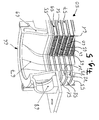
- FIG. 5 is a stacking disc block 50, as shown in the preceding figures according to various embodiments and views, shown in perspective in section.
- the stacking disk block 50 includes, among other things, three stacking disks 51 to 53 constructed and configured like the stacking disks in one of the foregoing embodiments.
- the stacking disks 51 to 53 delimit areas or layers 55 to 57 through which charge air flows.
- a corrugated ridge 59 to 61 is respectively arranged in the areas 55 to 57 through which charge air flows.
- Between two flow-through by charge air areas 55 to 57 each of a coolant flowed through area or a coolant flowing through layer 63 to 65 is arranged.
- the coolant in the layers 63 through 65 through which the coolant flows serves to dissipate heat emitted by the charge air into the regions 55 through 57 through which charge air flows.
- connection housing 66 Above the connection openings for charge air (12, 13 in Figure 1 and 32, 33 in FIG. 3 ) in the stacking disks 51 to 53, a connection housing 66 is provided.
- the connection housing 66 has a central charge air connection channel 67, which is arranged coaxially or in extension to the charge air connection openings in the stacking disks 51 to 53.
- the connection housing 66 has a coolant connection channel 68, which is arranged transversely to the charge air connection channel 67.
- the coolant connection channel 68 opens into a circulating coolant channel 69, which runs radially outside the central charge air connection channel 67.
- further coolant channels 71 to 73 are provided in the stacking disks 51 to 53.
- the coolant channels 71 to 73 are formed by oblong holes in the stacking disks 51 to 53. These elongated holes are denoted by 14 to 16, 34 to 36 and 44 to 46 in the preceding examples.
- connection housing 66 is a cast part made of solderable aluminum.
- the casting includes both the charge air port 67 and the coolant port 68. It is also possible to form the port housing 66 in multiple parts.
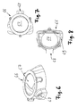
- the terminal housing 66 is shown in different views alone.
- the circulating coolant channel 69 serves to keep the outside temperature of the connection housing 66 low.
- the circulating coolant channel 69 completely surrounds the charge air connection channel 67 in cross section.
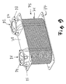
- FIG. 9 a charge air cooler 75 according to an embodiment of the invention is shown in perspective.
- the charge air cooler 75 includes a stacking disk block 76 having a plurality of stacking disks.
- the stacking disk block 76 is designed, for example, as in the Figures 1 and 2 However, the stacking disk block 76 may also be designed as in the FIGS. 3 and 4 illustrated stacking disk block 26.
- FIG. 5 a section through the intercooler 75 is shown in perspective. However, in FIG. 5 other reference numerals are used as in FIG. 9 ,
- the in FIG. 9 illustrated stacking disk block 76 is disposed between a bottom plate 77 and a lid 78.
- a charge air inlet port housing 81 and a charge air outlet port housing 82 are soldered to the lid 78.
- the terminal housings 81 and 82 may also be in one piece, For example, as a casting, be formed with the lid 78.
- the charge air inlet port housing 81 includes a charge air inlet port 84 and a coolant outlet port 85.
- the charge air outlet port housing 82 includes a charge air exit port 87 and a coolant input port 88.
- the inventive design of the intercooler 75 provides the advantage that the component outside temperature can be kept below 200 degrees Celsius.
- the design costs of the intercooler 75 according to the invention are reduced.
- the charge air cooler according to the invention provides more variable connection options than conventional intercoolers.
- the temperature gradients occurring during operation of the intercooler can be reduced. As a result, larger heights can be made possible.
- the maximum external component temperature results from the maximum coolant temperature and is preferably less than 200 degrees Celsius. This allows use on ships.
- boiling of the coolant is reliably prevented.
- a better stability and higher performance of the charge air cooler is made possible.
- the use of solderable casting eliminates the need to weld connecting parts after soldering.
- the use of a casting also provides the advantage that the connections to other components can be realized flexibly.
- both series and parallel circuits can be realized by a plurality of coolers.
- the component temperature is also lowered in the region of the charge air inlet to the level of the coolant temperature.
- unwanted voltages in the intercooler can be significantly reduced.
- larger construction heights that is, a stacking of a larger number of stacking disks possible.
- the pressure loss of the intercooler on the charge air and coolant side can be reduced and a higher heat output can be transmitted.
- a charge air cooler 90 which has four connection housings 91 to 94.
- the connection housing 91 includes a first charge air inlet port
- the terminal housing 93 includes a second charge air inlet port 99 and a second coolant output port 100.
- the connection housing 94 includes a second coolant input port 101 and a second charge air output port 102.
- the charge air connections 95 and 99 may also be closed.
- the charge air would enter the charge air cooler 90 through the charge air connection 102 of the connection housing 94.
- the course of the charge air in the intercooler 90 is indicated.
- the charge air would first pass through a high-temperature and then a low-temperature circuit in the charge air cooler 90 and exit the charge air cooler 90 at the charge air connection 98 of the connection housing 92.
- the connection housing 93 in this case would only have a high-temperature coolant inlet connection.
- the associated high-temperature coolant outlet port 101 would be provided in the terminal housing 94.
- the connector housing 91 would then comprise only a low-temperature coolant inlet port.
- the associated low-temperature coolant outlet port 97 would then be provided in the port housing 92.
- the first charge air cooler 111 includes a low-temperature coolant input port case 114 and a low-temperature coolant output port case 115. Connected to the low-temperature coolant output port case 115 is a high-temperature coolant input port case 116 of the second charge air cooler 112.
- the second charge air cooler 112 has a high-temperature coolant outlet connection housing 117.
- the first charge air cooler 111 forms a low-temperature charge air cooler.
- the second charge air cooler 112 forms a high temperature charge air cooler.
- the charge air passes through a charge air inlet port 119 through the low-temperature coolant input port housing 114 in the first charge air cooler 111 a.
- the high-temperature coolant outlet connection housing 117 is provided with the associated charge air outlet port 120.
Landscapes
- Engineering & Computer Science (AREA)
- Physics & Mathematics (AREA)
- Thermal Sciences (AREA)
- Mechanical Engineering (AREA)
- General Engineering & Computer Science (AREA)
- Heat-Exchange Devices With Radiators And Conduit Assemblies (AREA)
Priority Applications (1)
| Application Number | Priority Date | Filing Date | Title |
|---|---|---|---|
| PL06805664T PL1929232T3 (pl) | 2005-09-16 | 2006-09-07 | Wymiennik ciepła w postaci ułożonych w stos płyt, w szczególności chłodnica powietrza doładowującego |
Applications Claiming Priority (2)
| Application Number | Priority Date | Filing Date | Title |
|---|---|---|---|
| DE102005044291A DE102005044291A1 (de) | 2005-09-16 | 2005-09-16 | Stapelscheiben-Wärmeübertrager, insbesondere Ladeluftkühler |
| PCT/EP2006/008737 WO2007031230A1 (de) | 2005-09-16 | 2006-09-07 | Stapelscheiben-wärmeübertrager, insbesondere ladeluftkühler |
Publications (2)
| Publication Number | Publication Date |
|---|---|
| EP1929232A1 EP1929232A1 (de) | 2008-06-11 |
| EP1929232B1 true EP1929232B1 (de) | 2015-12-02 |
Family
ID=37591867
Family Applications (1)
| Application Number | Title | Priority Date | Filing Date |
|---|---|---|---|
| EP06805664.7A Active EP1929232B1 (de) | 2005-09-16 | 2006-09-07 | Stapelscheiben-wärmeübertrager, insbesondere ladeluftkühler |
Country Status (8)
| Country | Link |
|---|---|
| US (1) | US8393384B2 (pl) |
| EP (1) | EP1929232B1 (pl) |
| KR (1) | KR101300452B1 (pl) |
| CN (1) | CN101297172B (pl) |
| DE (1) | DE102005044291A1 (pl) |
| ES (1) | ES2563405T3 (pl) |
| PL (1) | PL1929232T3 (pl) |
| WO (1) | WO2007031230A1 (pl) |
Families Citing this family (19)
| Publication number | Priority date | Publication date | Assignee | Title |
|---|---|---|---|---|
| JP2005513403A (ja) * | 2001-12-21 | 2005-05-12 | ベール ゲーエムベーハー ウント コー カーゲー | 特に自動車用の熱交換器 |
| DE102006044154A1 (de) * | 2006-09-15 | 2008-05-21 | Behr Gmbh & Co. Kg | Stapelscheibenwärmetauscher zur Ladeluftkühlung |
| DE102008014375A1 (de) * | 2008-03-17 | 2009-09-24 | Behr Gmbh & Co. Kg | Gaskühler |
| CN102245993A (zh) * | 2008-12-17 | 2011-11-16 | 舒瑞普国际股份公司 | 半岛上的高压开口 |
| DE102010028660A1 (de) * | 2010-05-06 | 2011-11-10 | Behr Industry Gmbh & Co. Kg | Stapelscheiben-Wärmetauscher |
| US9032939B2 (en) * | 2012-08-20 | 2015-05-19 | Ford Global Technologies, Llc | Method for controlling a variable charge air cooler |
| US8794216B2 (en) * | 2012-09-14 | 2014-08-05 | GM Global Technology Operations LLC | Charge-air cooler |
| US9004046B2 (en) * | 2012-11-08 | 2015-04-14 | Ford Global Technologies, Llc | System and method to identify ambient conditions |
| DE102013205242A1 (de) * | 2013-03-25 | 2014-09-25 | Mahle International Gmbh | Abgaskühler |
| DE102014217920A1 (de) * | 2014-09-08 | 2016-03-10 | Mahle International Gmbh | Stapelscheiben-Wärmeübertrager |
| DE102015200952A1 (de) | 2015-01-21 | 2016-07-21 | Mahle International Gmbh | Stapelscheiben-Wärmeübertrager |
| US9848519B2 (en) * | 2015-04-15 | 2017-12-19 | Ford Global Technologies, Llc | Power module assembly and manifold |
| DE102016006127B4 (de) | 2015-06-08 | 2022-12-29 | Modine Manufacturing Company | Ladeluftkühler und Verfahren |
| DE102015215410A1 (de) * | 2015-08-12 | 2017-02-16 | Mahle International Gmbh | Stapelscheiben-Wärmeübertrager, insbesondere Ladeluftkühler |
| DE102015217092A1 (de) | 2015-09-07 | 2017-03-09 | Mahle International Gmbh | Brennkraftmaschine |
| DE102015220579A1 (de) | 2015-10-21 | 2017-04-27 | Mahle International Gmbh | Stapelscheiben-Wärmeübertrager |
| SE544093C2 (en) * | 2019-05-21 | 2021-12-21 | Alfa Laval Corp Ab | Plate heat exchanger, and a method of manufacturing a plate heat exchanger |
| CN110186300B (zh) * | 2019-06-27 | 2024-10-15 | 浙江银轮机械股份有限公司 | 板片、板片组件及热交换器 |
| CN112648867A (zh) * | 2020-11-30 | 2021-04-13 | 合肥通用机械研究院有限公司 | 一种强化传热的一体化扩散焊热交换器 |
Family Cites Families (21)
| Publication number | Priority date | Publication date | Assignee | Title |
|---|---|---|---|---|
| US3334399A (en) * | 1962-12-31 | 1967-08-08 | Stewart Warner Corp | Brazed laminated construction and method of fabrication thereof |
| US4291760A (en) * | 1978-06-22 | 1981-09-29 | Borg-Warner Corporation | Two fluid heat exchanger |
| US4823868A (en) * | 1988-05-26 | 1989-04-25 | Deere & Company | Intercooler and method of assembling the same |
| SE466871B (sv) * | 1990-04-17 | 1992-04-13 | Alfa Laval Thermal Ab | Plattfoeraangare med korrugerade plattor daer moenstrets orientering varieras i stroemningsriktningen saa att stroemningsmotstaandet successivt minskar |
| JPH06265284A (ja) | 1993-01-14 | 1994-09-20 | Nippondenso Co Ltd | 熱交換器 |
| SE9404077L (sv) * | 1994-11-24 | 1995-12-11 | Valeo Engine Cooling Ab | Anordning vid en förbränningsmotors insugningsrör |
| WO1998044305A1 (en) | 1997-04-02 | 1998-10-08 | Creare Inc. | Radial flow heat exchanger |
| AT2490U1 (de) * | 1997-11-28 | 1998-11-25 | Avl List Gmbh | Kühleranordnung für eine aufgeladene brennkraftmaschine mit abgasrückführung |
| DE19847213C1 (de) * | 1998-10-13 | 2000-02-10 | Dbb Fuel Cell Engines Gmbh | Verdampfereinheit |
| CA2260890A1 (en) | 1999-02-05 | 2000-08-05 | Long Manufacturing Ltd. | Self-enclosing heat exchangers |
| SE516178C2 (sv) * | 2000-03-07 | 2001-11-26 | Alfa Laval Ab | Värmeöverföringsplatta, plattpaket, plattvärmväxlare samt användning av platta respektive plattpaket för framställning av plattvärmeväxlare |
| SE516416C2 (sv) * | 2000-05-19 | 2002-01-15 | Alfa Laval Ab | Plattpaket, värmeöverföringsplatta, plattvärmeväxlaresamt anv ändning av värmeöverföringsplatta |
| CA2469323C (en) * | 2000-06-23 | 2007-01-23 | Dana Canada Corporation | Manifold for the transfer or distribution of two fluids |
| SE518256C2 (sv) * | 2001-01-04 | 2002-09-17 | Alfa Laval Ab | Värmeöverföringsplatta, plattpaket samt plattvärmeväxlare |
| DE10153877A1 (de) * | 2001-11-02 | 2003-05-15 | Behr Gmbh & Co | Wärmeübertrager |
| CA2384712A1 (en) | 2002-05-03 | 2003-11-03 | Michel St. Pierre | Heat exchanger with nest flange-formed passageway |
| CN2569084Y (zh) * | 2002-09-04 | 2003-08-27 | 井文工程股份有限公司 | 液化石油气水冷式热交换器 |
| US7063047B2 (en) | 2003-09-16 | 2006-06-20 | Modine Manufacturing Company | Fuel vaporizer for a reformer type fuel cell system |
| DE10352881A1 (de) * | 2003-11-10 | 2005-06-09 | Behr Gmbh & Co. Kg | Wärmeübertrager, insbesondere Ladeluft-/Kühlmittel-Kühler |
| DE10352880A1 (de) | 2003-11-10 | 2005-06-09 | Behr Gmbh & Co. Kg | Wärmeübertrager, insbesondere Ladeluft-/Kühlmittel-Kühler |
| DE102004018197A1 (de) | 2004-04-15 | 2005-11-03 | Modine Manufacturing Co., Racine | Abgaswärmetauscher |
-
2005
- 2005-09-16 DE DE102005044291A patent/DE102005044291A1/de not_active Withdrawn
-
2006
- 2006-09-07 US US12/066,901 patent/US8393384B2/en active Active
- 2006-09-07 PL PL06805664T patent/PL1929232T3/pl unknown
- 2006-09-07 ES ES06805664.7T patent/ES2563405T3/es active Active
- 2006-09-07 KR KR1020087009125A patent/KR101300452B1/ko active Active
- 2006-09-07 WO PCT/EP2006/008737 patent/WO2007031230A1/de not_active Ceased
- 2006-09-07 EP EP06805664.7A patent/EP1929232B1/de active Active
- 2006-09-07 CN CN2006800401960A patent/CN101297172B/zh active Active
Also Published As
| Publication number | Publication date |
|---|---|
| CN101297172B (zh) | 2010-09-29 |
| EP1929232A1 (de) | 2008-06-11 |
| US8393384B2 (en) | 2013-03-12 |
| ES2563405T3 (es) | 2016-03-15 |
| DE102005044291A1 (de) | 2007-03-29 |
| KR20080055921A (ko) | 2008-06-19 |
| US20080264619A1 (en) | 2008-10-30 |
| WO2007031230A1 (de) | 2007-03-22 |
| PL1929232T3 (pl) | 2016-06-30 |
| CN101297172A (zh) | 2008-10-29 |
| KR101300452B1 (ko) | 2013-09-10 |
Similar Documents
| Publication | Publication Date | Title |
|---|---|---|
| EP1929232B1 (de) | Stapelscheiben-wärmeübertrager, insbesondere ladeluftkühler | |
| EP1152204B1 (de) | Plattenwärmetauscher | |
| DE19549801B4 (de) | Plattenwärmetauscher | |
| DE102013101747B4 (de) | Kühler | |
| DE112015004523B4 (de) | Wärmetauscher mit selbsthaltender Bypassabdichtung | |
| EP2567172B1 (de) | Stapelscheiben-wärmetauscher | |
| EP1288604B1 (de) | Kühler und Verfahren zum Kühlen eines Mediums | |
| DE60310992T2 (de) | Hochdruckwärmetauscher | |
| DE202021102042U1 (de) | Zwei Wärmetauscher mit integriertem Umleitventil | |
| DE112018004787T5 (de) | Multi-fluid wärmetauscher | |
| DE102017119514B4 (de) | Wärmetauscher für ein Fahrzeug | |
| DE112013002728T5 (de) | Wärmetauscheranordnungen mit integriertem Ventil | |
| DE102006004249A1 (de) | Kühlvorrichtung mit Wärmetauscher durch Abgasrückführung | |
| EP2798297B1 (de) | Verfahren zur Herstellung von mehr als zwei unterschiedlichen Wärmeübertragern | |
| DE102015220579A1 (de) | Stapelscheiben-Wärmeübertrager | |
| EP0200809A2 (de) | Ölfilter mit integriertem Wärmetauscher | |
| DE10049890B4 (de) | Stapelscheiben-Wärmeübertrager | |
| EP3247960B1 (de) | Stapelscheiben-wärmeübertrager | |
| DE10336030A1 (de) | Wärmeübertrager sowie Platte für einen Wärmeübertrager | |
| WO2016037810A1 (de) | Stapelscheiben-wärmeübertrager | |
| DE102019215392A1 (de) | Stapelscheibenwärmetauscher | |
| DE202009004309U1 (de) | Wärmetauscher | |
| DE102025128321A1 (de) | Wärmetauscher | |
| DE102017214949A1 (de) | Wärmeübertrager | |
| DE102014212242A1 (de) | Wärmeübertrager |
Legal Events
| Date | Code | Title | Description |
|---|---|---|---|
| PUAI | Public reference made under article 153(3) epc to a published international application that has entered the european phase |
Free format text: ORIGINAL CODE: 0009012 |
|
| 17P | Request for examination filed |
Effective date: 20080416 |
|
| AK | Designated contracting states |
Kind code of ref document: A1 Designated state(s): AT BE BG CH CY CZ DE DK EE ES FI FR GB GR HU IE IS IT LI LT LU LV MC NL PL PT RO SE SI SK TR |
|
| 17Q | First examination report despatched |
Effective date: 20090518 |
|
| DAX | Request for extension of the european patent (deleted) | ||
| GRAP | Despatch of communication of intention to grant a patent |
Free format text: ORIGINAL CODE: EPIDOSNIGR1 |
|
| INTG | Intention to grant announced |
Effective date: 20150506 |
|
| GRAS | Grant fee paid |
Free format text: ORIGINAL CODE: EPIDOSNIGR3 |
|
| GRAA | (expected) grant |
Free format text: ORIGINAL CODE: 0009210 |
|
| AK | Designated contracting states |
Kind code of ref document: B1 Designated state(s): AT BE BG CH CY CZ DE DK EE ES FI FR GB GR HU IE IS IT LI LT LU LV MC NL PL PT RO SE SI SK TR |
|
| REG | Reference to a national code |
Ref country code: GB Ref legal event code: FG4D Free format text: NOT ENGLISH |
|
| REG | Reference to a national code |
Ref country code: AT Ref legal event code: REF Ref document number: 763817 Country of ref document: AT Kind code of ref document: T Effective date: 20151215 Ref country code: CH Ref legal event code: EP |
|
| REG | Reference to a national code |
Ref country code: IE Ref legal event code: FG4D Free format text: LANGUAGE OF EP DOCUMENT: GERMAN |
|
| REG | Reference to a national code |
Ref country code: DE Ref legal event code: R096 Ref document number: 502006014657 Country of ref document: DE |
|
| REG | Reference to a national code |
Ref country code: SE Ref legal event code: TRGR Ref country code: ES Ref legal event code: FG2A Ref document number: 2563405 Country of ref document: ES Kind code of ref document: T3 Effective date: 20160315 |
|
| REG | Reference to a national code |
Ref country code: NL Ref legal event code: MP Effective date: 20160302 |
|
| REG | Reference to a national code |
Ref country code: LT Ref legal event code: MG4D |
|
| PG25 | Lapsed in a contracting state [announced via postgrant information from national office to epo] |
Ref country code: LT Free format text: LAPSE BECAUSE OF FAILURE TO SUBMIT A TRANSLATION OF THE DESCRIPTION OR TO PAY THE FEE WITHIN THE PRESCRIBED TIME-LIMIT Effective date: 20151202 |
|
| PG25 | Lapsed in a contracting state [announced via postgrant information from national office to epo] |
Ref country code: LV Free format text: LAPSE BECAUSE OF FAILURE TO SUBMIT A TRANSLATION OF THE DESCRIPTION OR TO PAY THE FEE WITHIN THE PRESCRIBED TIME-LIMIT Effective date: 20151202 Ref country code: GR Free format text: LAPSE BECAUSE OF FAILURE TO SUBMIT A TRANSLATION OF THE DESCRIPTION OR TO PAY THE FEE WITHIN THE PRESCRIBED TIME-LIMIT Effective date: 20160303 Ref country code: NL Free format text: LAPSE BECAUSE OF FAILURE TO SUBMIT A TRANSLATION OF THE DESCRIPTION OR TO PAY THE FEE WITHIN THE PRESCRIBED TIME-LIMIT Effective date: 20151202 |
|
| PG25 | Lapsed in a contracting state [announced via postgrant information from national office to epo] |
Ref country code: IS Free format text: LAPSE BECAUSE OF FAILURE TO SUBMIT A TRANSLATION OF THE DESCRIPTION OR TO PAY THE FEE WITHIN THE PRESCRIBED TIME-LIMIT Effective date: 20151202 |
|
| PG25 | Lapsed in a contracting state [announced via postgrant information from national office to epo] |
Ref country code: CZ Free format text: LAPSE BECAUSE OF FAILURE TO SUBMIT A TRANSLATION OF THE DESCRIPTION OR TO PAY THE FEE WITHIN THE PRESCRIBED TIME-LIMIT Effective date: 20151202 |
|
| PG25 | Lapsed in a contracting state [announced via postgrant information from national office to epo] |
Ref country code: IS Free format text: LAPSE BECAUSE OF FAILURE TO SUBMIT A TRANSLATION OF THE DESCRIPTION OR TO PAY THE FEE WITHIN THE PRESCRIBED TIME-LIMIT Effective date: 20160402 Ref country code: SK Free format text: LAPSE BECAUSE OF FAILURE TO SUBMIT A TRANSLATION OF THE DESCRIPTION OR TO PAY THE FEE WITHIN THE PRESCRIBED TIME-LIMIT Effective date: 20151202 Ref country code: EE Free format text: LAPSE BECAUSE OF FAILURE TO SUBMIT A TRANSLATION OF THE DESCRIPTION OR TO PAY THE FEE WITHIN THE PRESCRIBED TIME-LIMIT Effective date: 20151202 Ref country code: RO Free format text: LAPSE BECAUSE OF FAILURE TO SUBMIT A TRANSLATION OF THE DESCRIPTION OR TO PAY THE FEE WITHIN THE PRESCRIBED TIME-LIMIT Effective date: 20151202 Ref country code: PT Free format text: LAPSE BECAUSE OF FAILURE TO SUBMIT A TRANSLATION OF THE DESCRIPTION OR TO PAY THE FEE WITHIN THE PRESCRIBED TIME-LIMIT Effective date: 20160404 |
|
| REG | Reference to a national code |
Ref country code: DE Ref legal event code: R097 Ref document number: 502006014657 Country of ref document: DE |
|
| REG | Reference to a national code |
Ref country code: FR Ref legal event code: PLFP Year of fee payment: 11 |
|
| PLBE | No opposition filed within time limit |
Free format text: ORIGINAL CODE: 0009261 |
|
| STAA | Information on the status of an ep patent application or granted ep patent |
Free format text: STATUS: NO OPPOSITION FILED WITHIN TIME LIMIT |
|
| PG25 | Lapsed in a contracting state [announced via postgrant information from national office to epo] |
Ref country code: DK Free format text: LAPSE BECAUSE OF FAILURE TO SUBMIT A TRANSLATION OF THE DESCRIPTION OR TO PAY THE FEE WITHIN THE PRESCRIBED TIME-LIMIT Effective date: 20151202 |
|
| 26N | No opposition filed |
Effective date: 20160905 |
|
| PG25 | Lapsed in a contracting state [announced via postgrant information from national office to epo] |
Ref country code: SI Free format text: LAPSE BECAUSE OF FAILURE TO SUBMIT A TRANSLATION OF THE DESCRIPTION OR TO PAY THE FEE WITHIN THE PRESCRIBED TIME-LIMIT Effective date: 20151202 |
|
| PG25 | Lapsed in a contracting state [announced via postgrant information from national office to epo] |
Ref country code: BE Free format text: LAPSE BECAUSE OF NON-PAYMENT OF DUE FEES Effective date: 20160930 |
|
| PG25 | Lapsed in a contracting state [announced via postgrant information from national office to epo] |
Ref country code: MC Free format text: LAPSE BECAUSE OF FAILURE TO SUBMIT A TRANSLATION OF THE DESCRIPTION OR TO PAY THE FEE WITHIN THE PRESCRIBED TIME-LIMIT Effective date: 20151202 |
|
| REG | Reference to a national code |
Ref country code: IE Ref legal event code: MM4A |
|
| PG25 | Lapsed in a contracting state [announced via postgrant information from national office to epo] |
Ref country code: IE Free format text: LAPSE BECAUSE OF NON-PAYMENT OF DUE FEES Effective date: 20160907 |
|
| PG25 | Lapsed in a contracting state [announced via postgrant information from national office to epo] |
Ref country code: LU Free format text: LAPSE BECAUSE OF NON-PAYMENT OF DUE FEES Effective date: 20160907 |
|
| REG | Reference to a national code |
Ref country code: FR Ref legal event code: PLFP Year of fee payment: 12 |
|
| PGFP | Annual fee paid to national office [announced via postgrant information from national office to epo] |
Ref country code: CH Payment date: 20170925 Year of fee payment: 12 Ref country code: IT Payment date: 20170922 Year of fee payment: 12 Ref country code: FI Payment date: 20170922 Year of fee payment: 12 |
|
| REG | Reference to a national code |
Ref country code: BE Ref legal event code: MM Effective date: 20160930 |
|
| PGFP | Annual fee paid to national office [announced via postgrant information from national office to epo] |
Ref country code: SE Payment date: 20170926 Year of fee payment: 12 Ref country code: PL Payment date: 20170828 Year of fee payment: 12 Ref country code: AT Payment date: 20170928 Year of fee payment: 12 |
|
| PGFP | Annual fee paid to national office [announced via postgrant information from national office to epo] |
Ref country code: ES Payment date: 20171025 Year of fee payment: 12 |
|
| PG25 | Lapsed in a contracting state [announced via postgrant information from national office to epo] |
Ref country code: HU Free format text: LAPSE BECAUSE OF FAILURE TO SUBMIT A TRANSLATION OF THE DESCRIPTION OR TO PAY THE FEE WITHIN THE PRESCRIBED TIME-LIMIT; INVALID AB INITIO Effective date: 20060907 Ref country code: CY Free format text: LAPSE BECAUSE OF FAILURE TO SUBMIT A TRANSLATION OF THE DESCRIPTION OR TO PAY THE FEE WITHIN THE PRESCRIBED TIME-LIMIT Effective date: 20151202 |
|
| PG25 | Lapsed in a contracting state [announced via postgrant information from national office to epo] |
Ref country code: BG Free format text: LAPSE BECAUSE OF FAILURE TO SUBMIT A TRANSLATION OF THE DESCRIPTION OR TO PAY THE FEE WITHIN THE PRESCRIBED TIME-LIMIT Effective date: 20151202 |
|
| REG | Reference to a national code |
Ref country code: FR Ref legal event code: PLFP Year of fee payment: 13 |
|
| PG25 | Lapsed in a contracting state [announced via postgrant information from national office to epo] |
Ref country code: FI Free format text: LAPSE BECAUSE OF NON-PAYMENT OF DUE FEES Effective date: 20180907 |
|
| REG | Reference to a national code |
Ref country code: SE Ref legal event code: EUG Ref country code: CH Ref legal event code: PL |
|
| REG | Reference to a national code |
Ref country code: AT Ref legal event code: MM01 Ref document number: 763817 Country of ref document: AT Kind code of ref document: T Effective date: 20180907 |
|
| PG25 | Lapsed in a contracting state [announced via postgrant information from national office to epo] |
Ref country code: SE Free format text: LAPSE BECAUSE OF NON-PAYMENT OF DUE FEES Effective date: 20180908 |
|
| PG25 | Lapsed in a contracting state [announced via postgrant information from national office to epo] |
Ref country code: IT Free format text: LAPSE BECAUSE OF NON-PAYMENT OF DUE FEES Effective date: 20180907 |
|
| PG25 | Lapsed in a contracting state [announced via postgrant information from national office to epo] |
Ref country code: CH Free format text: LAPSE BECAUSE OF NON-PAYMENT OF DUE FEES Effective date: 20180930 Ref country code: LI Free format text: LAPSE BECAUSE OF NON-PAYMENT OF DUE FEES Effective date: 20180930 |
|
| REG | Reference to a national code |
Ref country code: ES Ref legal event code: FD2A Effective date: 20191030 |
|
| PG25 | Lapsed in a contracting state [announced via postgrant information from national office to epo] |
Ref country code: AT Free format text: LAPSE BECAUSE OF NON-PAYMENT OF DUE FEES Effective date: 20180907 |
|
| PG25 | Lapsed in a contracting state [announced via postgrant information from national office to epo] |
Ref country code: ES Free format text: LAPSE BECAUSE OF NON-PAYMENT OF DUE FEES Effective date: 20180908 Ref country code: PL Free format text: LAPSE BECAUSE OF NON-PAYMENT OF DUE FEES Effective date: 20180907 |
|
| PGFP | Annual fee paid to national office [announced via postgrant information from national office to epo] |
Ref country code: TR Payment date: 20230905 Year of fee payment: 18 Ref country code: GB Payment date: 20230920 Year of fee payment: 18 |
|
| GBPC | Gb: european patent ceased through non-payment of renewal fee |
Effective date: 20240907 |
|
| PG25 | Lapsed in a contracting state [announced via postgrant information from national office to epo] |
Ref country code: GB Free format text: LAPSE BECAUSE OF NON-PAYMENT OF DUE FEES Effective date: 20240907 |
|
| PGFP | Annual fee paid to national office [announced via postgrant information from national office to epo] |
Ref country code: DE Payment date: 20250919 Year of fee payment: 20 |
|
| PGFP | Annual fee paid to national office [announced via postgrant information from national office to epo] |
Ref country code: FR Payment date: 20250919 Year of fee payment: 20 |