EP1928545B1 - Statut de parametre automatique sur un systeme de dispositif medical implantable - Google Patents
Statut de parametre automatique sur un systeme de dispositif medical implantable Download PDFInfo
- Publication number
- EP1928545B1 EP1928545B1 EP06802446A EP06802446A EP1928545B1 EP 1928545 B1 EP1928545 B1 EP 1928545B1 EP 06802446 A EP06802446 A EP 06802446A EP 06802446 A EP06802446 A EP 06802446A EP 1928545 B1 EP1928545 B1 EP 1928545B1
- Authority
- EP
- European Patent Office
- Prior art keywords
- medical device
- external monitor
- interrogation
- external
- imd
- Prior art date
- Legal status (The legal status is an assumption and is not a legal conclusion. Google has not performed a legal analysis and makes no representation as to the accuracy of the status listed.)
- Active
Links
- 239000012530 fluid Substances 0.000 claims description 29
- 238000000034 method Methods 0.000 claims description 21
- 238000012544 monitoring process Methods 0.000 claims description 19
- 230000006854 communication Effects 0.000 claims description 18
- 238000004891 communication Methods 0.000 claims description 18
- 230000005540 biological transmission Effects 0.000 claims description 13
- 230000004044 response Effects 0.000 claims description 13
- 230000002618 waking effect Effects 0.000 claims description 3
- 230000000638 stimulation Effects 0.000 description 13
- 238000007726 management method Methods 0.000 description 11
- 238000002560 therapeutic procedure Methods 0.000 description 11
- 238000001514 detection method Methods 0.000 description 10
- 230000006870 function Effects 0.000 description 8
- 238000012546 transfer Methods 0.000 description 7
- 230000000747 cardiac effect Effects 0.000 description 6
- 230000008859 change Effects 0.000 description 6
- 230000004962 physiological condition Effects 0.000 description 6
- 238000010586 diagram Methods 0.000 description 5
- 230000001953 sensory effect Effects 0.000 description 5
- 230000009471 action Effects 0.000 description 4
- 206010003119 arrhythmia Diseases 0.000 description 4
- NOESYZHRGYRDHS-UHFFFAOYSA-N insulin Chemical compound N1C(=O)C(NC(=O)C(CCC(N)=O)NC(=O)C(CCC(O)=O)NC(=O)C(C(C)C)NC(=O)C(NC(=O)CN)C(C)CC)CSSCC(C(NC(CO)C(=O)NC(CC(C)C)C(=O)NC(CC=2C=CC(O)=CC=2)C(=O)NC(CCC(N)=O)C(=O)NC(CC(C)C)C(=O)NC(CCC(O)=O)C(=O)NC(CC(N)=O)C(=O)NC(CC=2C=CC(O)=CC=2)C(=O)NC(CSSCC(NC(=O)C(C(C)C)NC(=O)C(CC(C)C)NC(=O)C(CC=2C=CC(O)=CC=2)NC(=O)C(CC(C)C)NC(=O)C(C)NC(=O)C(CCC(O)=O)NC(=O)C(C(C)C)NC(=O)C(CC(C)C)NC(=O)C(CC=2NC=NC=2)NC(=O)C(CO)NC(=O)CNC2=O)C(=O)NCC(=O)NC(CCC(O)=O)C(=O)NC(CCCNC(N)=N)C(=O)NCC(=O)NC(CC=3C=CC=CC=3)C(=O)NC(CC=3C=CC=CC=3)C(=O)NC(CC=3C=CC(O)=CC=3)C(=O)NC(C(C)O)C(=O)N3C(CCC3)C(=O)NC(CCCCN)C(=O)NC(C)C(O)=O)C(=O)NC(CC(N)=O)C(O)=O)=O)NC(=O)C(C(C)CC)NC(=O)C(CO)NC(=O)C(C(C)O)NC(=O)C1CSSCC2NC(=O)C(CC(C)C)NC(=O)C(NC(=O)C(CCC(N)=O)NC(=O)C(CC(N)=O)NC(=O)C(NC(=O)C(N)CC=1C=CC=CC=1)C(C)C)CC1=CN=CN1 NOESYZHRGYRDHS-UHFFFAOYSA-N 0.000 description 4
- 239000011159 matrix material Substances 0.000 description 4
- 238000005259 measurement Methods 0.000 description 4
- 230000035790 physiological processes and functions Effects 0.000 description 4
- 206010030113 Oedema Diseases 0.000 description 3
- 230000006793 arrhythmia Effects 0.000 description 3
- 230000000694 effects Effects 0.000 description 3
- 210000004072 lung Anatomy 0.000 description 3
- 230000000737 periodic effect Effects 0.000 description 3
- 230000029058 respiratory gaseous exchange Effects 0.000 description 3
- 102000004877 Insulin Human genes 0.000 description 2
- 108090001061 Insulin Proteins 0.000 description 2
- 206010037423 Pulmonary oedema Diseases 0.000 description 2
- 239000008280 blood Substances 0.000 description 2
- 210000004369 blood Anatomy 0.000 description 2
- 238000012377 drug delivery Methods 0.000 description 2
- 230000000004 hemodynamic effect Effects 0.000 description 2
- 229940125396 insulin Drugs 0.000 description 2
- 210000003205 muscle Anatomy 0.000 description 2
- 238000012545 processing Methods 0.000 description 2
- 208000005333 pulmonary edema Diseases 0.000 description 2
- 206010007559 Cardiac failure congestive Diseases 0.000 description 1
- 206010019280 Heart failures Diseases 0.000 description 1
- 230000009286 beneficial effect Effects 0.000 description 1
- 230000007175 bidirectional communication Effects 0.000 description 1
- 230000036772 blood pressure Effects 0.000 description 1
- 210000005242 cardiac chamber Anatomy 0.000 description 1
- 238000010835 comparative analysis Methods 0.000 description 1
- 230000003750 conditioning effect Effects 0.000 description 1
- 238000011161 development Methods 0.000 description 1
- 238000002405 diagnostic procedure Methods 0.000 description 1
- 239000002934 diuretic Substances 0.000 description 1
- 238000011863 diuretic therapy Methods 0.000 description 1
- 229940030606 diuretics Drugs 0.000 description 1
- 229940079593 drug Drugs 0.000 description 1
- 239000003814 drug Substances 0.000 description 1
- 238000002651 drug therapy Methods 0.000 description 1
- 238000011156 evaluation Methods 0.000 description 1
- 230000036541 health Effects 0.000 description 1
- 230000000977 initiatory effect Effects 0.000 description 1
- 238000012986 modification Methods 0.000 description 1
- 230000004048 modification Effects 0.000 description 1
- 238000012806 monitoring device Methods 0.000 description 1
- 230000002232 neuromuscular Effects 0.000 description 1
- 230000003287 optical effect Effects 0.000 description 1
- 230000001575 pathological effect Effects 0.000 description 1
- 210000000115 thoracic cavity Anatomy 0.000 description 1
- 230000001960 triggered effect Effects 0.000 description 1
Images

Classifications
-
- A—HUMAN NECESSITIES
- A61—MEDICAL OR VETERINARY SCIENCE; HYGIENE
- A61B—DIAGNOSIS; SURGERY; IDENTIFICATION
- A61B5/00—Measuring for diagnostic purposes; Identification of persons
- A61B5/0002—Remote monitoring of patients using telemetry, e.g. transmission of vital signals via a communication network
- A61B5/0031—Implanted circuitry
-
- A—HUMAN NECESSITIES
- A61—MEDICAL OR VETERINARY SCIENCE; HYGIENE
- A61B—DIAGNOSIS; SURGERY; IDENTIFICATION
- A61B5/00—Measuring for diagnostic purposes; Identification of persons
- A61B5/0002—Remote monitoring of patients using telemetry, e.g. transmission of vital signals via a communication network
-
- A—HUMAN NECESSITIES
- A61—MEDICAL OR VETERINARY SCIENCE; HYGIENE
- A61B—DIAGNOSIS; SURGERY; IDENTIFICATION
- A61B5/00—Measuring for diagnostic purposes; Identification of persons
- A61B5/68—Arrangements of detecting, measuring or recording means, e.g. sensors, in relation to patient
- A61B5/6846—Arrangements of detecting, measuring or recording means, e.g. sensors, in relation to patient specially adapted to be brought in contact with an internal body part, i.e. invasive
- A61B5/6847—Arrangements of detecting, measuring or recording means, e.g. sensors, in relation to patient specially adapted to be brought in contact with an internal body part, i.e. invasive mounted on an invasive device
- A61B5/686—Permanently implanted devices, e.g. pacemakers, other stimulators, biochips
-
- A—HUMAN NECESSITIES
- A61—MEDICAL OR VETERINARY SCIENCE; HYGIENE
- A61B—DIAGNOSIS; SURGERY; IDENTIFICATION
- A61B5/00—Measuring for diagnostic purposes; Identification of persons
- A61B5/68—Arrangements of detecting, measuring or recording means, e.g. sensors, in relation to patient
- A61B5/6846—Arrangements of detecting, measuring or recording means, e.g. sensors, in relation to patient specially adapted to be brought in contact with an internal body part, i.e. invasive
- A61B5/6867—Arrangements of detecting, measuring or recording means, e.g. sensors, in relation to patient specially adapted to be brought in contact with an internal body part, i.e. invasive specially adapted to be attached or implanted in a specific body part
- A61B5/6869—Heart
-
- A—HUMAN NECESSITIES
- A61—MEDICAL OR VETERINARY SCIENCE; HYGIENE
- A61N—ELECTROTHERAPY; MAGNETOTHERAPY; RADIATION THERAPY; ULTRASOUND THERAPY
- A61N1/00—Electrotherapy; Circuits therefor
- A61N1/18—Applying electric currents by contact electrodes
- A61N1/32—Applying electric currents by contact electrodes alternating or intermittent currents
- A61N1/36—Applying electric currents by contact electrodes alternating or intermittent currents for stimulation
- A61N1/362—Heart stimulators
- A61N1/37—Monitoring; Protecting
- A61N1/3702—Physiological parameters
-
- A—HUMAN NECESSITIES
- A61—MEDICAL OR VETERINARY SCIENCE; HYGIENE
- A61N—ELECTROTHERAPY; MAGNETOTHERAPY; RADIATION THERAPY; ULTRASOUND THERAPY
- A61N1/00—Electrotherapy; Circuits therefor
- A61N1/18—Applying electric currents by contact electrodes
- A61N1/32—Applying electric currents by contact electrodes alternating or intermittent currents
- A61N1/36—Applying electric currents by contact electrodes alternating or intermittent currents for stimulation
- A61N1/372—Arrangements in connection with the implantation of stimulators
- A61N1/37211—Means for communicating with stimulators
- A61N1/37252—Details of algorithms or data aspects of communication system, e.g. handshaking, transmitting specific data or segmenting data
- A61N1/37254—Pacemaker or defibrillator security, e.g. to prevent or inhibit programming alterations by hackers or unauthorised individuals
-
- G—PHYSICS
- G08—SIGNALLING
- G08B—SIGNALLING OR CALLING SYSTEMS; ORDER TELEGRAPHS; ALARM SYSTEMS
- G08B21/00—Alarms responsive to a single specified undesired or abnormal condition and not otherwise provided for
- G08B21/02—Alarms for ensuring the safety of persons
- G08B21/0202—Child monitoring systems using a transmitter-receiver system carried by the parent and the child
- G08B21/0205—Specific application combined with child monitoring using a transmitter-receiver system
- G08B21/0211—Combination with medical sensor, e.g. for measuring heart rate, temperature
-
- G—PHYSICS
- G16—INFORMATION AND COMMUNICATION TECHNOLOGY [ICT] SPECIALLY ADAPTED FOR SPECIFIC APPLICATION FIELDS
- G16H—HEALTHCARE INFORMATICS, i.e. INFORMATION AND COMMUNICATION TECHNOLOGY [ICT] SPECIALLY ADAPTED FOR THE HANDLING OR PROCESSING OF MEDICAL OR HEALTHCARE DATA
- G16H40/00—ICT specially adapted for the management or administration of healthcare resources or facilities; ICT specially adapted for the management or operation of medical equipment or devices
- G16H40/40—ICT specially adapted for the management or administration of healthcare resources or facilities; ICT specially adapted for the management or operation of medical equipment or devices for the management of medical equipment or devices, e.g. scheduling maintenance or upgrades
-
- G—PHYSICS
- G16—INFORMATION AND COMMUNICATION TECHNOLOGY [ICT] SPECIALLY ADAPTED FOR SPECIFIC APPLICATION FIELDS
- G16H—HEALTHCARE INFORMATICS, i.e. INFORMATION AND COMMUNICATION TECHNOLOGY [ICT] SPECIALLY ADAPTED FOR THE HANDLING OR PROCESSING OF MEDICAL OR HEALTHCARE DATA
- G16H40/00—ICT specially adapted for the management or administration of healthcare resources or facilities; ICT specially adapted for the management or operation of medical equipment or devices
- G16H40/60—ICT specially adapted for the management or administration of healthcare resources or facilities; ICT specially adapted for the management or operation of medical equipment or devices for the operation of medical equipment or devices
- G16H40/67—ICT specially adapted for the management or administration of healthcare resources or facilities; ICT specially adapted for the management or operation of medical equipment or devices for the operation of medical equipment or devices for remote operation
-
- G—PHYSICS
- G16—INFORMATION AND COMMUNICATION TECHNOLOGY [ICT] SPECIALLY ADAPTED FOR SPECIFIC APPLICATION FIELDS
- G16H—HEALTHCARE INFORMATICS, i.e. INFORMATION AND COMMUNICATION TECHNOLOGY [ICT] SPECIALLY ADAPTED FOR THE HANDLING OR PROCESSING OF MEDICAL OR HEALTHCARE DATA
- G16H50/00—ICT specially adapted for medical diagnosis, medical simulation or medical data mining; ICT specially adapted for detecting, monitoring or modelling epidemics or pandemics
- G16H50/30—ICT specially adapted for medical diagnosis, medical simulation or medical data mining; ICT specially adapted for detecting, monitoring or modelling epidemics or pandemics for calculating health indices; for individual health risk assessment
-
- A—HUMAN NECESSITIES
- A61—MEDICAL OR VETERINARY SCIENCE; HYGIENE
- A61B—DIAGNOSIS; SURGERY; IDENTIFICATION
- A61B5/00—Measuring for diagnostic purposes; Identification of persons
- A61B5/48—Other medical applications
- A61B5/4869—Determining body composition
- A61B5/4875—Hydration status, fluid retention of the body
-
- A—HUMAN NECESSITIES
- A61—MEDICAL OR VETERINARY SCIENCE; HYGIENE
- A61B—DIAGNOSIS; SURGERY; IDENTIFICATION
- A61B5/00—Measuring for diagnostic purposes; Identification of persons
- A61B5/74—Details of notification to user or communication with user or patient ; user input means
- A61B5/746—Alarms related to a physiological condition, e.g. details of setting alarm thresholds or avoiding false alarms
Definitions
- the present invention relates generally to implantable medical device systems and more particularly to an implantable medical device system and method for providing the status of a monitored parameter.
- IMDs implantable medical devices
- Such devices can be configured for delivering therapies, such as cardiac pacemakers and defibrillators, hemodynamic monitors, drug delivery devices, insulin monitors and pumps, neurostimulators, and muscle stimulators. These devices may detect clinically serious or life-threatening conditions related to physiological events or conditions.
- Such devices are also typically enabled to perform self-diagnostic tests or otherwise monitor device performance issues, such as battery life-expectancy, electrical lead impedance, frequency of delivered therapies, and so on.
- the advanced capabilities of IMDs in detecting physiological or device-related conditions that may warrant careful monitoring, clinical attention or even emergency care has motivated the addition of real time patient notification features to IMD systems.
- Home monitors are external devices that can communicate with the IMD to retrieve data relating to device performance or physiological conditions.
- the use of home monitors for displaying or broadcasting a patient warning or notification has been proposed, such that the patient is aware of a condition that warrants further monitoring or attention.
- the home monitor is generally coupled to a communication network to transmit IMD data via the communication network to a remote patient management center. Health care professionals can thereby respond appropriately to the device-related and physiological data retrieved. Interrogation of the IMD by the home monitor and transfer of data to the remote patient management center can occur on a scheduled, periodic basis.
- the IMD may be enabled to transmit data to the home monitor upon detecting a triggering event corresponding to a predetermined alert condition.
- a real-time warning alerts the patient that a condition requiring medical attention or warranting close monitoring or action by the patient has been detected.
- the home monitor may display a notification of the alert condition to the patient or other caregiver and/or transmit the data to the remote patient management center.
- further updates of the parameter causing the alert condition are generally not available.
- the patient or clinician is not notified if the alert condition persists for a period of time or if the alert condition is no longer present. Updated data may not be remotely retrieved from the IMD until another triggering event, the next scheduled interrogation session or until a clinician manually schedules an interrogation.
- the present invention is directed toward providing an up-to-date status of a physiological parameter by an IMD.
- data stored by an IMD was generally retrieved only during an interrogation session during a clinical office visit.
- an IMD can be interrogated on a more frequent, scheduled basis according to an interrogation schedule programmed into the remote patient management system.
- An unscheduled data transmission may occur when the IMD detects a predefined alert level of a monitored physiological parameter. Since the transmission occurs once in response to an alert level detection, the duration that the monitored physiological parameter remains at an alert level and whether the monitored physiological parameter returns to a non-alert level may remain unknown until the next scheduled interrogation.
- the invention is directed toward scheduling additional IMD interrogations at predetermined time intervals by the external monitor so that updated physiological parameter values can be retrieved following detection of an alert level.
- retrieving the updated data comprises waking up the IMD telemetry circuit in response to expiration of previously set timers, and sending an interrogation command from the external monitor to the IMD after the predetermined time interval.
- An up-to-date status of the monitored physiological parameter is thereby available for the patient and/or clinician, irrespective of any previously programmed interrogation session schedule stored within the remote patient management system.
- the invention is further directed to canceling pending scheduled interrogation sessions if the monitored physiological parameter corresponds to a non-alert level.
- US Patent Application Publication 2003/144711 A1 (Pless et al. ), which is regarded as the closest prior art to the present invention, discloses an implantable medical device (IMD) capable of communicating with an external monitor. In case an alert level of a monitored parameter is detected, a follow-up interrogation session is scheduled, during which updated data is retrieved from the IMD.
- IMD implantable medical device
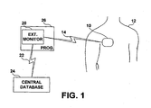
- FIG. 1 illustrates an IMD system including an external monitor for communicating with the IMD.
- IMD 10 is shown implanted in a patient 12.
- the simplified illustration of IMD 10 may represent a variety of IMDs such as cardiac pacemakers, implantable cardioverter defibrillators, hemodynamic monitors, ECG recorders, drug delivery devices, insulin monitors or pumps, or neuromuscular stimulators.
- IMD 10 may be coupled to one or more leads or fluid delivery catheters. Leads may be used for carrying electrodes or physiological sensors used for monitoring one or more physiological conditions and delivering electrical stimulation therapies.
- IMD 10 may alternatively be embodied as a leadless device wherein sensors or electrodes are incorporated in or on the housing of IMD 10. Examples of lead less monitoring devices are generally disclosed in U.S. Pat. No. 5,404,877 issued to Nolan et al. , and U.S. Pat. No. 5,987,352 issued to Klein et al.
- IMD 10 is provided with an antenna and associated circuitry, as will be described below, for establishing a communication link 14 with external monitor 20.
- External monitor 20 may be embodied as a dedicated device for communicating with IMD 10 and performing patient alert functions as will be described herein.
- external monitor 20 may be implemented as a component of a home programmer or monitoring unit 26 which includes other IMD programming and interrogation functions. Programmer and home monitoring units for use with an IMD are known in the art.
- patient alert information can be transferred to the external monitor 20 from IMD 10 through bi-directional communication link 14.
- External monitor 20 may optionally be adapted to communicate with a central database 24 to allow transfer of patient alert data and any other physiological or device-related data received from IMD 10 to the central database 24.
- Central database 24 also referred to herein as "remote patient management database,” may be an Internet-based or other networked database used for remote patient monitoring.
- External monitor 20 may transfer data via a communication link 22, which may be established via the Internet, a local area network, a wide area network, a telecommunications network or other appropriate communications network and may be a wireless communication link.
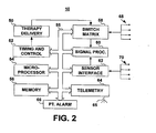
- FIG. 2 is a block diagram of typical functional components of an IMD, such as IMD 10 shown in FIG. 1 .
- IMD 10 generally includes timing and control circuitry 52 and an operating system that may employ microprocessor 54 or other operating system architecture such as a digital state machine for timing sensing and therapy delivery functions in accordance with a programmed operating mode.
- Microprocessor 54 and associated memory 56 are coupled to the various components of IMD 10 via a data/address bus 55.
- IMD 10 may include therapy delivery unit 50 for delivering a therapy, such as an electrical stimulation or drug therapy, under the control of timing and control 52.
- therapy delivery unit 50 is typically coupled to two or more electrodes 68 via a switch matrix 58.
- Switch matrix 58 is used for selecting which electrodes and corresponding polarities are used for delivering electrical stimulation pulses.
- Electrodes 68 may also be used for sensing electrical signals within the body, such as cardiac signals, or for measuring impedance. In the case of cardiac stimulation devices, cardiac electrical signals are sensed for determining when an electrical stimulation therapy is needed and in controlling the timing of stimulation pulses. In some embodiments, detection of an arrhythmia is a patient alert condition, causing IMD 10 to issue a patient alert signal.
- Electrodes used for sensing and electrodes used for stimulation may be selected via switch matrix 58.
- electrodes 68 are coupled to signal processing circuitry 60 via switch matrix 58.
- Signal processor 60 includes sense amplifiers and may include other signal conditioning circuitry and an analog to digital converter. Electrical signals may then be used by microprocessor 54 for detecting physiological events, such as detecting and discriminating cardiac arrhythmias.
- electrodes 68 may be used for measuring impedance signals for monitoring edema, respiration or heart chamber volume. Any of these signals may be used to detect a change or level indicating a worsening pathologic condition, which may trigger a patient alert signal. Impedance signals can also be used for monitoring lead performance and detecting lead-related problems as is known in the art.
- IMD 10 may additionally or alternatively be coupled to one or more physiological sensors 70.
- sensors may include pressure sensors, accelerometers, flow sensors, blood chemistry sensors, activity sensors or other physiological sensors known for use with IMDs.
- Sensors 70 are coupled to IMD 10 via a sensor interface 62 which provides sensor signals to signal processing circuitry 60.
- Sensor signals are used by microprocessor 54 for detecting physiological events or conditions.
- IMD 10 may monitor heart wall motion, blood pressure, blood chemistry, respiration, or patient activity. Monitored signals may be used for sensing the need for delivering a therapy under control of the operating system.
- Physiological events or changes in monitored physiological conditions may be defined as triggering conditions for a patient alert signal to be generated by IMD 10.
- the operating system includes associated memory 56 for storing a variety of programmed-in operating mode and parameter values that are used by microprocessor 54.
- the memory 56 may also be used for storing data compiled from sensed physiological signals and/or relating to device operating history for telemetry out on receipt of a retrieval or interrogation instruction. All of these functions and operations are known in the art, and generally employed to store operating commands and data for controlling device operation and for later retrieval to diagnose device function or patient condition.
- parameter values, limits or ranges defining one or more alert trigger conditions may be stored in memory 56 and used by microprocessor 54 in detecting an alert level.
- IMD 10 further includes telemetry circuitry 64 and antenna 65. Programming commands or data are transmitted during uplink or downlink telemetry between IMD telemetry circuitry 64 and external telemetry circuitry included in the external monitor.
- Telemetry circuitry 64 and antenna 65 may correspond to telemetry systems known in the art. Upon detection of a predefined alert level of a physiological or device-related parameter, IMD 10 initiates a telemetry session with the external monitor. Data is transmitted to the external monitor corresponding to the monitored parameter causing the alert condition. Transmitted data may include any other available physiological or device-related data and time and date information.
- Telemetry circuitry 64 is embodied as a long range telemetry system that allows alert data to be transferred automatically when it is available without intervention by the patient.
- Long-range telemetry systems are generally disclosed in U.S. Pat. No. 6,482,154 issued to Haubrich et al.
- telemetry circuitry may require patient intervention to initiate or enable transfer of patient alert data to an external monitor.
- telemetry circuitry 64 may require the use of an external programming head containing an external antenna to be positioned over IMD 10 as generally disclosed in U.S. Pat. No. 5,354,319 issued to Wyborny et al.
- Telemetry circuitry 64 may require manual "waking up" by the patient to enable data transmission or may require the patient to be within a limited communication range from the external monitor.
- IMD 10 includes a patient alarm 66 for notifying the patient that data is ready to be transmitted to the external monitor.
- IMD 10 may be equipped with patient alarm circuitry 66 for generating audible tones, a perceptible vibration, muscle stimulation or other sensory stimulation for notifying the patient that a patient alert condition has been detected by IMD 10 and a data transmission is pending.
- the patient is previously advised to initiate a communication session between the IMD 10 and the external monitor upon perceiving a sensory patient alarm.
- the generation of a patient alert signal upon detection of triggering condition causes IMD 10 to generate a sensory patient alarm by alarm 66 and prepare for or automatically initiate a patient alert data transmission via telemetry circuitry 64 to the external monitor.
- a patient alert condition may be defined with regard to any of the monitoring functions provided by IMD 10.
- the operating system of IMD 10 performs a comparative analysis of sensed signals, or parameters derived there from, to determine if predefined alert triggering conditions are present. If a predefined trigger condition is detected, a patient alert trigger signal 92 is generated. In one embodiment, the patient alert trigger signal 92 causes IMD 10 to "wake up" telemetry circuitry 64 to automatically transfer patient alert data to external monitor 20 via telemetry link 14 (shown in FIG. 1 ).
- the patient alert trigger signal may cause patient alarm 66 to generate sensory stimulation to the patient.
- a patient alert trigger signal causes patient alarm 66 to generate sensory stimulation such that the patient initiates a patient alert data transfer to external monitor 20.
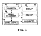
- FIG. 3 is a functional block diagram of an external monitor 20.
- External monitor 20 will typically include a telemetry circuit 72 for receiving data from IMD 10.
- External monitor 20 may be a microprocessor-controlled device wherein microprocessor 74 operates with associated memory 78 for controlling monitor functions.
- microprocessor 74 In response to an alert condition data transmission received from IMD 10, microprocessor 74 will schedule subsequent interrogation sessions for retrieving data from IMD 10 at a future time. In this way, external monitor 20 retrieves updated values for the monitored parameter that triggered the alert condition.
- external monitor 20 may generate a message on display 76.
- the message will contain information based on the alert data received from IMD 10 and updated monitor parameter values.
- External monitor 20 may further include a speaker 77 for generating audible sounds to notify the patient that a transmission has occurred and/or an alert message is being displayed.
- Display 76 may be a graphical screen allowing for textual or graphical displays. Alternatively display 76 may include LEDs for indicating the presence of an alert condition.
- External monitor 20 may include a communications module 79, which may be embodied as a modem, to allow data transmission via a communication network. External monitor 20 may transmit data to a remote patient management database or place a telephone call or send electronic messages to notify the patient, caregivers or medical personnel of the presence of an alert condition and updated parameter values obtained during subsequently scheduled interrogation sessions.
- a communications module 79 which may be embodied as a modem, to allow data transmission via a communication network.
- External monitor 20 may transmit data to a remote patient management database or place a telephone call or send electronic messages to notify the patient, caregivers or medical personnel of the presence of an alert condition and updated parameter values obtained during subsequently scheduled interrogation sessions.
- external monitor 20 includes a user interface 73 for entering commands or programming information if external monitor 20 is enabled to perform programming functions.
- User interface 73 may be used to manually trigger a data transmission to a communication network via communication module 79 and/or a data retrieval from IMD 10 via telemetry circuit 72.
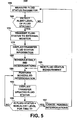
- FIG. 4 is flow chart summarizing a method for providing an updated status of a parameter monitored by an IMD according to an embodiment of the present invention.
- the IMD detects a predefined alert level of a monitored parameter.
- Method 100 may be applied to any parameter monitored by the IMD, which may include device-related parameters and physiological parameters.
- An alert level may be a predefined value, range of values, or threshold crossing of the monitored parameter.
- Alert conditions may be defined for multiple parameters such that method 100 may be invoked by detecting an alert level of more than one monitored parameter and may be operating simultaneously for providing an updated status of multiple monitored parameters.
- the IMD responds to the detected alert level by transmitting data relating to the alert level detection to the external monitor.
- the transmitted data may be a signal indicating that an alert level has been detected and indicating the corresponding monitored parameter.
- the transmitted data may include actual parameter values, a history of parameter values, other monitored parameter values, time and date information or any other relevant data.
- the external monitor may display alert data information to inform the patient or another caregiver of the alert condition.
- the display may be an LED display indicating the presence of the alert condition.
- the number or color of LEDs illuminated may be used to indicate the severity of the alert condition or the type of alert condition detected.
- the display may include graphical or textual display on a monitor and/or a broadcast audible sound or voiced message. It is appreciated that numerous variations for displaying or broadcasting alert condition information to a patient or other caregiver may be implemented.
- the external monitor may additionally or alternatively transfer alert condition data to a remote patient management database at step 115 via a communication network. Medical personnel may then respond appropriately to the alert condition.
- the external monitor responds to the alert condition data receipt by scheduling a future IMD interrogation.
- the IMD interrogation may be scheduled to occur at any time interval, for example after several minutes, several hours, one day, or one week. The appropriate time interval may depend on the type of monitored parameter for which the alert level detection was made. For example, an arrhythmia condition may change over the course of seconds or minutes but an edema condition may change over the course of a day.
- Some parameters may be monitored in a continuous manner by the IMD such that any time a follow-up interrogation is performed by the external monitor, an updated parameter value will be obtained. Other parameters may be monitored on a periodic basis by the IMD. A scheduled interrogation by the external monitor should therefore occur after the next periodic measurement is expected in order to obtain an updated parameter value. If the monitoring interval is unknown by the external monitor, interrogations may be repeated until an updated parameter value is obtained.
- the time interval for scheduling follow-up interrogations for a particular monitored parameter may also be tailored according to individual patient need. Some patients may be at greater risk for requiring hospitalization or emergency care following an alert level. As such, frequent follow-up interrogations may be scheduled to closely monitor a parameter that has reached an alert level.
- a patient may respond to the alert notification by taking or adjusting a medication, adjusting his/her activity level, adjusting fluid intake, or taking any other physician-directed action.
- the patient's response may resolve the condition that caused the alert level detection without requiring the patient to go to a clinic or other medical facility.
- Scheduling follow-up interrogation sessions by the external monitor allow the patient or other caregiver to observe whether a patient's response to the alert have had a beneficial effect.
- the patient can seek medical attention in a timely manner when the condition is not quickly resolved by the patient's own response to the alert notification. Hospitalization or other serious consequences may thereby be avoided.
- the alert data is transmitted to a remote patient management system and may not be displayed to notify the patient of the condition. Medical personnel may then advise the patient appropriately and continue to monitor the status of the condition via the scheduled follow-up interrogation. Medical personnel can make informed decisions regarding the appropriate time to intervene based on an up-to-date status of the monitored parameter retrieved during scheduled follow-up interrogations.
- scheduling of a follow-up IMD interrogation session at step 120 may be performed through programming operations initiated by the remote patient management system.
- a programming request may be sent back to the external monitor in response to receiving the alert data by the remote patient management database.
- the external monitor responds by transferring the scheduled interrogation session data to the IMD.
- the scheduled interrogation is performed.
- the external monitor initiates the interrogation session by transferring an interrogation command to the IMD.
- the scheduled interrogation session may not require patient intervention and occur automatically through a long-range telemetry system.
- the IMD will "wake up" the IMD telemetry circuitry upon the expiration of timers set according to the scheduled interrogation session and is thereby enabled to receive the interrogation request.
- the patient or another caregiver may be required to intervene to ensure the IMD telemetry circuitry is enabled and the IMD is within telemetry range of the external monitor for a scheduled, follow-up interrogation.
- data corresponding to the monitored parameter that caused the previous alert level detection is uplinked to the external monitor.
- updated monitored parameter values and/or the status of the alert condition are retrieved.
- Other data such as other device-related or physiological parameter data, time and data information, or other relevant data may optionally be retrieved.
- the updated monitored parameter data is displayed by the external monitor and/or transferred to a remote patient management center.
- a determination is made whether the updated parameter value remains at an alert level. If so, another follow-up interrogation session is scheduled at step 120. If the parameter value has returned to a non-alert level, method 100 may be terminated at step 140. The patient and/or medical personnel have been notified at step 130 of the non-alert status of the monitored parameter and further follow-up interrogations are no longer needed.
- one or more additional follow-up interrogations may be scheduled after detecting a non-alert level of the monitored parameter to ensure that the monitored parameter remains at a non-alert level for a predetermined interval of time.
- FIG. 5 is a flow chart summarizing a method for providing an updated fluid status on an external monitor.
- Patients suffering from congestive heart failure can develop pulmonary edema. Such patients are often medicated with diuretics to manage the fluid level. Careful monitoring of a patient's lung wetness can help in managing the diuretic therapy and prevent severe cases of pulmonary edema which would require hospitalization.
- an updated fluid status parameter is retrieved through scheduled follow-up interrogations following detection of an alert level of the fluid status.
- the patient or clinician can take appropriate action to address an edemic or over-diuresed condition in a timely manner.
- a fluid status parameter is measured by the IMD.
- measurement of a fluid status parameter includes monitoring an impedance signal for detecting a change in thoracic impedance relating to a change in lung wetness, which may be discerned through evaluation of a change in respiration.
- Edema monitoring methods may be embodied as generally disclosed, for example, in U.S. Pat. No. 6,512,949 issued to Combs, et al. Other methods known for use in IMDs for detecting changes in lung wetness may be substituted.
- method 150 determines if the measured fluid status parameter value is at an alert level.
- An alert level may indicate a low fluid status which may be associated with an over-diruresed condition.
- Another alert level may indicate a high fluid status associated with an edemic condition.
- more than one alert level may be defined for any monitored parameter indicating different types of physiological conditions that can be indicated by the monitored parameter.
- the IMD continues measuring the fluid status parameter at step 155 according to the programmed monitoring mode. If an alert level is detected at step 160, the IMD initiates a data transmission at step 170.
- the fluid status parameter data is transferred to the external monitor.
- alert condition information may be displayed by the external monitor and/or transferred to a remote patient management database.
- an LED display on the external monitor may indicate to the patient that the fluid status is at an alert level.
- One color of LED may be illuminated to indicate a low fluid status alert condition; a different color of LED may be illuminated to indicate a high fluid status condition.
- Other parameter data or information may optionally be displayed on a screen or broadcast by the external monitor.
- the external monitor automatically responds to the receipt of a fluid status alert transmission by scheduling a future IMD interrogation at step 180.
- a series of IMD interrogations may be scheduled occurring at an appropriate time interval.
- the external monitor may schedule a series of daily IMD interrogations as indicated by step 180.
- the series of IMD interrogations may be scheduled to occur at a selected time interval for an indefinite period of time or a predetermined number of IMD interrogations may be scheduled.
- the scheduled, follow-up IMD interrogation is performed to retrieve a new fluid status parameter measurement that has been obtained at step 185, prior to the follow-up interrogation.
- Information relating to the new fluid status parameter value may be displayed or broadcast by the external monitor and/or transferred to a remote patient management database at step 193.
- the external monitor determines if the fluid status parameter is at a non-alert level. The external monitor may further determine if the parameter has remained at a non-alert level for a predefined interval of time. For example, the external monitor may determine if the fluid status parameter has been at a non-alert level for at least 24 hours or for two successive follow-up interrogations. If not, the next scheduled interrogation is performed at step 190.
- Method 150 returns to step 155 to continue IMD measurements of the fluid status parameter.
- a scheduled series of follow-up interrogations may expire prior to the monitored parameter reaching a non-alert level at which time the patient and/or medical personnel may take appropriate action.
- Some of the techniques described above may be embodied as a computer-readable medium comprising instructions for a programmable processor such as a microprocessor.
- the programmable processor may include one or more individual processors, which may act independently or in concert.
- a "computer-readable medium” includes but is not limited to any type of computer memory such as floppy disks, conventional hard disks, CR-ROMS, Flash ROMS, nonvolatile ROMS, RAM and a magnetic or optical storage medium.
- the medium may include instructions for causing a processor to perform any of the features described above for initiating a session of the escape rate variation according to the present invention.
Landscapes
- Health & Medical Sciences (AREA)
- Engineering & Computer Science (AREA)
- Life Sciences & Earth Sciences (AREA)
- Biomedical Technology (AREA)
- General Health & Medical Sciences (AREA)
- Public Health (AREA)
- Medical Informatics (AREA)
- Heart & Thoracic Surgery (AREA)
- Animal Behavior & Ethology (AREA)
- Veterinary Medicine (AREA)
- Biophysics (AREA)
- Business, Economics & Management (AREA)
- Physics & Mathematics (AREA)
- Pathology (AREA)
- General Business, Economics & Management (AREA)
- Molecular Biology (AREA)
- Surgery (AREA)
- Primary Health Care (AREA)
- Epidemiology (AREA)
- Radiology & Medical Imaging (AREA)
- Nuclear Medicine, Radiotherapy & Molecular Imaging (AREA)
- Cardiology (AREA)
- Computer Networks & Wireless Communication (AREA)
- Child & Adolescent Psychology (AREA)
- Physiology (AREA)
- Emergency Management (AREA)
- General Physics & Mathematics (AREA)
- Data Mining & Analysis (AREA)
- Databases & Information Systems (AREA)
- Measuring And Recording Apparatus For Diagnosis (AREA)
- Electrotherapy Devices (AREA)
Claims (11)
- Procédé pour fournir l'état d'un paramètre physiologique dans un système de dispositif médical implantable, comportant les étapes consistant à :surveiller le paramètre physiologique ;détecter un niveau d'alerte du paramètre surveillé ;transmettre des données correspondant au niveau d'alerte détecté du dispositif médical implanté à un moniteur externe ;programmer, par l'intermédiaire dudit moniteur externe, une série de sessions d'interrogation de suivi qui doivent avoir lieu à des intervalles de temps prédéterminés en réponse à la transmission de données de niveau d'alerte et régler des compteurs de durée en fonction des intervalles de temps prédéterminés ;récupérer des données mises à jour à partir du dispositif médical implanté correspondant au paramètre physiologique surveillé pendant les sessions d'interrogation de suivi ;déterminer, dans ledit moniteur externe, si les données mises à jour récupérées correspondant au paramètre physiologique surveillé correspondent à un niveau de non-alerte ; et annuler toutes les sessions d'interrogation programmées en attente de la série programmée en réponse aux données mises à jour récupérées déterminées comme correspondant à un niveau de non-alerte, dans lequel la récupération des données mises à jour pendant chacune des sessions d'interrogation de suivi comporte le réveil du circuit de télémesure du dispositif médical implantable en réponse à l'expiration des compteurs de durée et l'envoi d'une commande d'interrogation du moniteur externe au dispositif médical implantable après l'intervalle de temps prédéterminé.
- Procédé selon la revendication 1, comportant en outre l'affichage d'informations correspondant aux données mises à jour récupérées, sur le moniteur externe.
- Procédé selon la revendication 1, comportant également le transfert des données mises à jour récupérées à une base de données de gestion de patients à distance.
- Procédé selon la revendication 3, dans lequel la programmation d'une session d'interrogation de suivi comporte le transfert d'une demande de programmation de la base de données de gestion de patients à distance au moniteur externe.
- Procédé selon la revendication 1, comportant en outre l'étape consistant à déterminer si les données mises à jour correspondant au paramètre surveillé correspondent à un niveau de non-alerte pendant un intervalle de temps prédéterminé.
- Procédé selon la revendication 1, dans lequel le paramètre physiologique surveillé par le dispositif médical implantée inclut un état de fluide.
- Système de dispositif médical implantable, comportant :un dispositif médical implantable, comportant :un capteur implantable (68) pour détecter un signal correspondant à un paramètre physiologique ;un processeur (54) couplé au capteur pour recevoir le signal de capteur et détecter un niveau d'alerte du paramètre physiologique sur la base du signal de capteur ;un circuit de télémesure de dispositif (64) couplé au processeur pour transmettre des données correspondant au paramètre physiologique en réponse au processeur détectant le niveau d'alerte ;un moniteur externe (20), comportant :un circuit de télémesure externe (72) adapté pour une communication avec le circuit de télémesure de dispositif pour recevoir les données transmises ; etun système de commande externe (74), couplé au circuit de télémesure externe, pour programmer une série de sessions d'interrogation de suivi qui doivent avoir lieu à des intervalles de temps prédéterminés, pour récupérer une valeur mise à jour à partir du processeur correspondant au paramètre physiologique via une communication entre le circuit de télémesure externe et le circuit de télémesure de dispositif, ledit système de commande externe déterminant si les données mises à jour récupérées correspondant au paramètre physiologique surveillé correspondent à un niveau de non-alerte ; et annuler toutes les sessions d'interrogation programmées en attente de la série programmée en réponse aux données mises à jour récupérées déterminées comme correspondant à un niveau de non-alerte, dans lequel la récupération des données mises à jour pendant chacune des sessions d'interrogation de suivi comporte l'envoi d'une commande d'interrogation du moniteur externe au dispositif médical implantable après l'intervalle de temps prédéterminé.
- Système de dispositif médical implantable selon la revendication 7, dans lequel ledit moniteur externe comporte un affichage externe pour afficher des informations correspondant au paramètre physiologique.
- Système de dispositif médical implantable selon la revendication 7, comportant en outre :une base de données de gestion de patients à distance (24) ;un réseau de communication (22) ; etun module de communication externe (26) couplé au réseau de communication pour transférer des informations reçues par le circuit de télémesure externe correspondant au paramètre physiologique surveillé, à la base de données de gestion de patients à distance.
- Système selon la revendication 7, dans lequel le capteur comporte un capteur d'impédance pour surveiller un état de fluide.
- Support lisible par ordinateur ayant des instructions exécutables sur ordinateur qui, lorsqu'elles sont exécutées sur le système selon l'une quelconque des revendications 7 à 10, amènent ledit dispositif à mettre en oeuvre le procédé selon l'une quelconque des revendications 1 à 6 pour fournir l'état d'un paramètre dans un système de dispositif médical implantable.
Applications Claiming Priority (2)
| Application Number | Priority Date | Filing Date | Title |
|---|---|---|---|
| US11/217,028 US8827904B2 (en) | 2005-08-31 | 2005-08-31 | Automatic parameter status on an implantable medical device system |
| PCT/US2006/033459 WO2007027570A1 (fr) | 2005-08-31 | 2006-08-25 | Statut de parametre automatique sur un systeme de dispositif medical implantable |
Publications (2)
| Publication Number | Publication Date |
|---|---|
| EP1928545A1 EP1928545A1 (fr) | 2008-06-11 |
| EP1928545B1 true EP1928545B1 (fr) | 2013-01-02 |
Family
ID=37575269
Family Applications (1)
| Application Number | Title | Priority Date | Filing Date |
|---|---|---|---|
| EP06802446A Active EP1928545B1 (fr) | 2005-08-31 | 2006-08-25 | Statut de parametre automatique sur un systeme de dispositif medical implantable |
Country Status (5)
| Country | Link |
|---|---|
| US (1) | US8827904B2 (fr) |
| EP (1) | EP1928545B1 (fr) |
| JP (1) | JP4881382B2 (fr) |
| CA (1) | CA2620597A1 (fr) |
| WO (1) | WO2007027570A1 (fr) |
Families Citing this family (80)
| Publication number | Priority date | Publication date | Assignee | Title |
|---|---|---|---|---|
| US8912908B2 (en) | 2005-04-28 | 2014-12-16 | Proteus Digital Health, Inc. | Communication system with remote activation |
| US8730031B2 (en) | 2005-04-28 | 2014-05-20 | Proteus Digital Health, Inc. | Communication system using an implantable device |
| US9198608B2 (en) | 2005-04-28 | 2015-12-01 | Proteus Digital Health, Inc. | Communication system incorporated in a container |
| US8836513B2 (en) | 2006-04-28 | 2014-09-16 | Proteus Digital Health, Inc. | Communication system incorporated in an ingestible product |
| CN103259027A (zh) | 2005-04-28 | 2013-08-21 | 普罗透斯数字保健公司 | 药物信息系统 |
| US8802183B2 (en) | 2005-04-28 | 2014-08-12 | Proteus Digital Health, Inc. | Communication system with enhanced partial power source and method of manufacturing same |
| EP1920418A4 (fr) | 2005-09-01 | 2010-12-29 | Proteus Biomedical Inc | Systeme de communications sans fil implantable |
| WO2007130491A2 (fr) * | 2006-05-02 | 2007-11-15 | Proteus Biomedical, Inc. | Régimes thérapeutiques personnalisés pour un patient |
| US20080021287A1 (en) * | 2006-06-26 | 2008-01-24 | Woellenstein Matthias D | System and method for adaptively adjusting patient data collection in an automated patient management environment |
| EP2087589B1 (fr) | 2006-10-17 | 2011-11-23 | Proteus Biomedical, Inc. | Oscillateur basse tension pour dispositifs médicaux |
| KR101611240B1 (ko) | 2006-10-25 | 2016-04-11 | 프로테우스 디지털 헬스, 인코포레이티드 | 복용 가능한 제어된 활성화 식별자 |
| WO2008063626A2 (fr) | 2006-11-20 | 2008-05-29 | Proteus Biomedical, Inc. | Récepteurs de signaux de santé personnelle à traitement actif du signal |
| WO2008095183A2 (fr) | 2007-02-01 | 2008-08-07 | Proteus Biomedical, Inc. | Systèmes de marqueur d'événement ingérable |
| CA3000257C (fr) | 2007-02-14 | 2020-04-28 | Proteus Digital Health, Inc. | Source d'energie integree au corps ayant une electrode de zone de surface superieure |
| US9270025B2 (en) | 2007-03-09 | 2016-02-23 | Proteus Digital Health, Inc. | In-body device having deployable antenna |
| EP2124725A1 (fr) | 2007-03-09 | 2009-12-02 | Proteus Biomedical, Inc. | Dispositif dans le corps ayant un émetteur multidirectionnel |
| US9943234B2 (en) * | 2007-04-17 | 2018-04-17 | Cardiac Pacemakers, Inc. | Using respiration distress manifestations for heart failure detection |
| US8271080B2 (en) * | 2007-05-23 | 2012-09-18 | Cardiac Pacemakers, Inc. | Decongestive therapy titration for heart failure patients using implantable sensor |
| US8115618B2 (en) | 2007-05-24 | 2012-02-14 | Proteus Biomedical, Inc. | RFID antenna for in-body device |
| US8649858B2 (en) | 2007-06-25 | 2014-02-11 | Boston Scientific Neuromodulation Corporation | Architectures for an implantable medical device system |
| PT2192946T (pt) * | 2007-09-25 | 2022-11-17 | Otsuka Pharma Co Ltd | Dispositivo no corpo com amplificação de sinal dipolo virtual |
| WO2009055202A1 (fr) | 2007-10-24 | 2009-04-30 | Medtronic, Inc. | Titrage à distance de thérapie administrée par un dispositif médical implantable |
| DE102007051756A1 (de) * | 2007-10-30 | 2009-05-07 | Biotronik Crm Patent Ag | Vorrichtung zur Bestimmung eines Nachsorgetermins für die Versorgung eines implantierbaren medizinischen Gerätes |
| JP5794782B2 (ja) * | 2007-11-27 | 2015-10-14 | プロテウス デジタル ヘルス, インコーポレイテッド | 通信チャネルを採用するトランスボディ通信システム |
| DK3235491T3 (da) | 2008-03-05 | 2021-02-08 | Otsuka Pharma Co Ltd | Spiselige hændelsesmarkeringsenheder og systemer med multimodus-kommunikation |
| US8069135B2 (en) * | 2008-03-20 | 2011-11-29 | General Electric Company | Systems and methods for a predictive notification engine |
| US8959200B2 (en) * | 2008-07-01 | 2015-02-17 | Ortho-Clinical Diagnostics, Inc. | Event-based communication in a clinical diagnostic analyzer |
| ES2696984T3 (es) | 2008-07-08 | 2019-01-21 | Proteus Digital Health Inc | Infraestructura de datos de marcadores de eventos de ingestión |
| US8290791B2 (en) * | 2008-07-29 | 2012-10-16 | Medtronic, Inc. | Patient management system |
| WO2010019778A2 (fr) | 2008-08-13 | 2010-02-18 | Proteus Biomedical, Inc. | Circuits pouvant être ingérés |
| JP5411943B2 (ja) | 2008-11-13 | 2014-02-12 | プロテウス デジタル ヘルス, インコーポレイテッド | 摂取可能な治療起動装置システムおよび方法 |
| US8055334B2 (en) | 2008-12-11 | 2011-11-08 | Proteus Biomedical, Inc. | Evaluation of gastrointestinal function using portable electroviscerography systems and methods of using the same |
| US9659423B2 (en) | 2008-12-15 | 2017-05-23 | Proteus Digital Health, Inc. | Personal authentication apparatus system and method |
| US9439566B2 (en) | 2008-12-15 | 2016-09-13 | Proteus Digital Health, Inc. | Re-wearable wireless device |
| TWI503101B (zh) | 2008-12-15 | 2015-10-11 | Proteus Digital Health Inc | 與身體有關的接收器及其方法 |
| SG172847A1 (en) | 2009-01-06 | 2011-08-29 | Proteus Biomedical Inc | Pharmaceutical dosages delivery system |
| CN102341031A (zh) | 2009-01-06 | 2012-02-01 | 普罗秋斯生物医学公司 | 摄取相关的生物反馈和个人化医学治疗方法和系统 |
| US8540664B2 (en) | 2009-03-25 | 2013-09-24 | Proteus Digital Health, Inc. | Probablistic pharmacokinetic and pharmacodynamic modeling |
| SG10201810784SA (en) | 2009-04-28 | 2018-12-28 | Proteus Digital Health Inc | Highly Reliable Ingestible Event Markers And Methods For Using The Same |
| EP2432458A4 (fr) | 2009-05-12 | 2014-02-12 | Proteus Digital Health Inc | Marqueurs d'événement ingérables comprenant un composant ingérable |
| US20110034783A1 (en) * | 2009-08-10 | 2011-02-10 | Nellcor Puritan Bennett Llc | Systems and methods for balancing power consumption and utility of wireless medical sensors |
| WO2011022732A2 (fr) | 2009-08-21 | 2011-02-24 | Proteus Biomedical, Inc. | Appareil et procédé pour mesurer des paramètres biochimiques |
| TWI517050B (zh) | 2009-11-04 | 2016-01-11 | 普羅托斯數位健康公司 | 供應鏈管理之系統 |
| UA109424C2 (uk) | 2009-12-02 | 2015-08-25 | Фармацевтичний продукт, фармацевтична таблетка з електронним маркером і спосіб виготовлення фармацевтичної таблетки | |
| MX2012008922A (es) | 2010-02-01 | 2012-10-05 | Proteus Digital Health Inc | Sistema de recoleccion de datos. |
| AU2011237612B2 (en) | 2010-04-07 | 2016-05-12 | Otsuka Pharmaceutical Co., Ltd. | Miniature ingestible device |
| TWI557672B (zh) | 2010-05-19 | 2016-11-11 | 波提亞斯數位康健公司 | 用於從製造商跟蹤藥物直到患者之電腦系統及電腦實施之方法、用於確認將藥物給予患者的設備及方法、患者介面裝置 |
| US9107806B2 (en) | 2010-11-22 | 2015-08-18 | Proteus Digital Health, Inc. | Ingestible device with pharmaceutical product |
| JP2014514032A (ja) | 2011-03-11 | 2014-06-19 | プロテウス デジタル ヘルス, インコーポレイテッド | 様々な物理的構成を備えた着用式個人身体関連装置 |
| WO2015112603A1 (fr) | 2014-01-21 | 2015-07-30 | Proteus Digital Health, Inc. | Produit ingérable pouvant être mâché et système de communication associé |
| US9756874B2 (en) | 2011-07-11 | 2017-09-12 | Proteus Digital Health, Inc. | Masticable ingestible product and communication system therefor |
| KR101898964B1 (ko) | 2011-07-21 | 2018-09-14 | 프로테우스 디지털 헬스, 인코포레이티드 | 모바일 통신 장치, 시스템, 및 방법 |
| US9235683B2 (en) | 2011-11-09 | 2016-01-12 | Proteus Digital Health, Inc. | Apparatus, system, and method for managing adherence to a regimen |
| WO2014018454A1 (fr) | 2012-07-23 | 2014-01-30 | Proteus Digital Health, Inc. | Techniques de fabrication de marqueurs d'événements ingérables comprenant un constituant ingérable |
| ES2683709T3 (es) | 2012-10-18 | 2018-09-27 | Proteus Digital Health, Inc. | Aparato, sistema, y procedimiento para optimizar de manera adaptativa la disipación de energía y la energía de difusión en una fuente de energía para un dispositivo de comunicación |
| WO2014120669A1 (fr) | 2013-01-29 | 2014-08-07 | Proteus Digital Health, Inc. | Films polymères hautement dilatables et compositions les contenant |
| US9238144B2 (en) * | 2013-03-14 | 2016-01-19 | Neuropace, Inc. | Optimizing data retrieval from an active implantable medical device |
| JP6498177B2 (ja) | 2013-03-15 | 2019-04-10 | プロテウス デジタル ヘルス, インコーポレイテッド | 本人認証装置システムおよび方法 |
| JP5941240B2 (ja) | 2013-03-15 | 2016-06-29 | プロテウス デジタル ヘルス, インコーポレイテッド | 金属検出器装置、システム、および方法 |
| EP3968263A1 (fr) | 2013-06-04 | 2022-03-16 | Otsuka Pharmaceutical Co., Ltd. | Système, appareil et procédés de collecte de données et d'évaluation des résultats |
| US9796576B2 (en) | 2013-08-30 | 2017-10-24 | Proteus Digital Health, Inc. | Container with electronically controlled interlock |
| CA2965941C (fr) | 2013-09-20 | 2020-01-28 | Proteus Digital Health, Inc. | Procedes, dispositifs et systemes de reception et de decodage de signal en presence de bruit a l'aide de tranches et d'une distorsion |
| JP2016537924A (ja) | 2013-09-24 | 2016-12-01 | プロテウス デジタル ヘルス, インコーポレイテッド | 事前に正確に把握されていない周波数において受信された電磁信号に関する使用のための方法および装置 |
| US10084880B2 (en) | 2013-11-04 | 2018-09-25 | Proteus Digital Health, Inc. | Social media networking based on physiologic information |
| US11955236B2 (en) | 2015-04-20 | 2024-04-09 | Murj, Inc. | Systems and methods for managing patient medical devices |
| US11051543B2 (en) | 2015-07-21 | 2021-07-06 | Otsuka Pharmaceutical Co. Ltd. | Alginate on adhesive bilayer laminate film |
| US10886011B2 (en) * | 2015-12-02 | 2021-01-05 | Icahn School Of Medicine At Mount Sinai | Systems and methods for optimizing management of patients with medical devices and monitoring compliance |
| US20170316673A1 (en) * | 2016-04-28 | 2017-11-02 | Bryan Gorr | Automated Fluid Condition Monitoring Multi-Sensor, Transceiver and Status Display Hub |
| ES2738384T3 (es) * | 2016-07-07 | 2020-01-22 | Lindacare Nv | Manejo de transmisiones de dispositivos médicos |
| CA3124272C (fr) | 2016-07-22 | 2023-08-08 | Proteus Digital Health, Inc. | Detection electromagnetique et detection de marqueurs d'evenements a ingerer |
| IL265827B2 (en) | 2016-10-26 | 2023-03-01 | Proteus Digital Health Inc | Methods for producing capsules with ingestible event markers |
| US11766550B2 (en) * | 2017-05-21 | 2023-09-26 | Veris Health, Inc. | Implantable medication infusion port with physiologic monitoring |
| US11877857B2 (en) | 2017-09-13 | 2024-01-23 | Hologic, Inc. | Wireless active monitoring implant system |
| USD906357S1 (en) | 2018-04-05 | 2020-12-29 | Murj, Inc. | Display screen or portion thereof with graphical user interface for a health management application |
| US11096582B2 (en) | 2018-11-20 | 2021-08-24 | Veris Health Inc. | Vascular access devices, systems, and methods for monitoring patient health |
| EP3806106A1 (fr) * | 2019-10-10 | 2021-04-14 | Koninklijke Philips N.V. | Support de décision clinique extensible |
| JP2023530621A (ja) * | 2020-06-30 | 2023-07-19 | バイオトロニック エスエー アンド カンパニー カーゲー | アクティブな埋め込み型医療デバイスを含む医療システム及びその動作の方法 |
| US20220230743A1 (en) * | 2021-01-21 | 2022-07-21 | Medtronic, Inc. | Medical device management using risk control measures |
| EP4398980A1 (fr) * | 2021-09-09 | 2024-07-17 | BIOTRONIK SE & Co. KG | Dispositif patient pour système de communication de stimulateur cardiaque sans fil |
| US11456072B1 (en) * | 2022-03-15 | 2022-09-27 | Murj, Inc. | Systems and methods to distribute cardiac device advisory data |
Citations (1)
| Publication number | Priority date | Publication date | Assignee | Title |
|---|---|---|---|---|
| US20040117204A1 (en) * | 2002-12-17 | 2004-06-17 | Cardiac Pacemakers, Inc. | Repeater device for communications with an implantable medical device |
Family Cites Families (18)
| Publication number | Priority date | Publication date | Assignee | Title |
|---|---|---|---|---|
| US5404877A (en) | 1993-06-04 | 1995-04-11 | Telectronics Pacing Systems, Inc. | Leadless implantable sensor assembly and a cardiac emergency warning alarm |
| EP0944414B1 (fr) | 1996-07-11 | 2005-11-09 | Medtronic, Inc. | Dispositif implantable peu invasif permettant de surveiller des evenements physiologiques |
| US6250309B1 (en) | 1999-07-21 | 2001-06-26 | Medtronic Inc | System and method for transferring information relating to an implantable medical device to a remote location |
| US6442433B1 (en) | 1999-10-26 | 2002-08-27 | Medtronic, Inc. | Apparatus and method for remote troubleshooting, maintenance and upgrade of implantable device systems |
| US6418346B1 (en) | 1999-12-14 | 2002-07-09 | Medtronic, Inc. | Apparatus and method for remote therapy and diagnosis in medical devices via interface systems |
| US6480745B2 (en) | 1999-12-24 | 2002-11-12 | Medtronic, Inc. | Information network interrogation of an implanted device |
| EP1949851A3 (fr) | 2000-03-17 | 2010-05-26 | Medtronic, Inc. | Résumé immédiat d'un moniteur d'insuffisance cardiaque pour systèmes de gestion de patient |
| US6574511B2 (en) | 2000-04-21 | 2003-06-03 | Medtronic, Inc. | Passive data collection system from a fleet of medical instruments and implantable devices |
| EP1296744A2 (fr) | 2000-06-23 | 2003-04-02 | Medtronic, Inc. | Liaison sans fil rf compatible en reseau pour la gestion des donnees d'un dispositif medical |
| US6694177B2 (en) * | 2001-04-23 | 2004-02-17 | Cardionet, Inc. | Control of data transmission between a remote monitoring unit and a central unit |
| US20030144711A1 (en) | 2002-01-29 | 2003-07-31 | Neuropace, Inc. | Systems and methods for interacting with an implantable medical device |
| US6957107B2 (en) * | 2002-03-13 | 2005-10-18 | Cardionet, Inc. | Method and apparatus for monitoring and communicating with an implanted medical device |
| US7127300B2 (en) * | 2002-12-23 | 2006-10-24 | Cardiac Pacemakers, Inc. | Method and apparatus for enabling data communication between an implantable medical device and a patient management system |
| US7359753B2 (en) * | 2004-04-07 | 2008-04-15 | Cardiac Pacemakers, Inc. | System and method for RF wake-up of implantable medical device |
| US20060017575A1 (en) | 2004-07-20 | 2006-01-26 | Medtronic, Inc. | Alert system and method for an implantable medical device |
| US7265676B2 (en) | 2004-07-20 | 2007-09-04 | Medtronic, Inc. | Alert system and method for an implantable medical device |
| US7261691B1 (en) * | 2004-08-02 | 2007-08-28 | Kwabena Asomani | Personalized emergency medical monitoring and transmission system |
| US20060064136A1 (en) | 2004-09-23 | 2006-03-23 | Medtronic, Inc. | Method and apparatus for facilitating patient alert in implantable medical devices |
-
2005
- 2005-08-31 US US11/217,028 patent/US8827904B2/en active Active
-
2006
- 2006-08-25 CA CA002620597A patent/CA2620597A1/fr not_active Abandoned
- 2006-08-25 WO PCT/US2006/033459 patent/WO2007027570A1/fr active Application Filing
- 2006-08-25 EP EP06802446A patent/EP1928545B1/fr active Active
- 2006-08-25 JP JP2008529150A patent/JP4881382B2/ja active Active
Patent Citations (1)
| Publication number | Priority date | Publication date | Assignee | Title |
|---|---|---|---|---|
| US20040117204A1 (en) * | 2002-12-17 | 2004-06-17 | Cardiac Pacemakers, Inc. | Repeater device for communications with an implantable medical device |
Also Published As
| Publication number | Publication date |
|---|---|
| JP2009505793A (ja) | 2009-02-12 |
| EP1928545A1 (fr) | 2008-06-11 |
| JP4881382B2 (ja) | 2012-02-22 |
| CA2620597A1 (fr) | 2007-03-08 |
| US8827904B2 (en) | 2014-09-09 |
| US20070060797A1 (en) | 2007-03-15 |
| WO2007027570A1 (fr) | 2007-03-08 |
Similar Documents
| Publication | Publication Date | Title |
|---|---|---|
| EP1928545B1 (fr) | Statut de parametre automatique sur un systeme de dispositif medical implantable | |
| US20060064136A1 (en) | Method and apparatus for facilitating patient alert in implantable medical devices | |
| US8438039B2 (en) | User customizable workflow preferences for remote patient management | |
| US8033998B2 (en) | Device and method for automatic threshold setting | |
| US8155742B2 (en) | Remote communication system with availability indicator for an implantable medical device | |
| US8052610B2 (en) | Event registration for automatic threshold setting | |
| EP1809376B1 (fr) | Procede et dispositif de telemesure longue portee sans danger pour dispositifs medicaux implantables | |
| US20060161214A1 (en) | Method of graphical display of link status and fail-safe mechanism for safety during real-time medical device therapy | |
| US20060161213A1 (en) | Method of graphical display of link status and fail-safe mechanism for safety during real-time medical device therapy | |
| EP2505132A1 (fr) | Algorithme chez un patient destiné à gérer la décompensation | |
| US20040259494A1 (en) | Systems, devices, and methods for selectively preventing data transfer from a medical device | |
| EP1744665A1 (fr) | Systeme, procede et dispositif de gestion d'evenement physiologique ; dispositif de surveillance et produit-programme | |
| JP2008541235A (ja) | 自動患者管理システムにおける警告通知の管理 | |
| US9486153B2 (en) | Medical device system having an implanted medical device and an external device | |
| US11357439B1 (en) | Advanced cardiovascular monitoring system with personalized st-segment thresholds | |
| US8090566B2 (en) | Battery longevity monitoring | |
| EP1802371B1 (fr) | Traitement et acces a distance a des informations de systemes implantes | |
| US20210369213A1 (en) | System for generating an alert for a systemic infection | |
| US20230233083A1 (en) | System for Generating an Alert for a Systemic Infection | |
| CN118251728A (zh) | 被配置为提高健康事件诊断的准确性的联网系统 |
Legal Events
| Date | Code | Title | Description |
|---|---|---|---|
| PUAI | Public reference made under article 153(3) epc to a published international application that has entered the european phase |
Free format text: ORIGINAL CODE: 0009012 |
|
| 17P | Request for examination filed |
Effective date: 20080313 |
|
| AK | Designated contracting states |
Kind code of ref document: A1 Designated state(s): AT BE BG CH CY CZ DE DK EE ES FI FR GB GR HU IE IS IT LI LT LU LV MC NL PL PT RO SE SI SK TR |
|
| RIN1 | Information on inventor provided before grant (corrected) |
Inventor name: BALL, JAMES J. Inventor name: HOUSE, CHRIS T. Inventor name: MCADAMS, SEAN B. |
|
| 17Q | First examination report despatched |
Effective date: 20080708 |
|
| RIN1 | Information on inventor provided before grant (corrected) |
Inventor name: HOUSE, CHRIS T. Inventor name: BALL, JAMES J. Inventor name: MCADAMS, SEAN B. |
|
| REG | Reference to a national code |
Ref country code: DE Ref legal event code: R079 Ref document number: 602006034004 Country of ref document: DE Free format text: PREVIOUS MAIN CLASS: A61N0001370000 Ipc: A61B0005000000 |
|
| DAX | Request for extension of the european patent (deleted) | ||
| GRAP | Despatch of communication of intention to grant a patent |
Free format text: ORIGINAL CODE: EPIDOSNIGR1 |
|
| RIC1 | Information provided on ipc code assigned before grant |
Ipc: A61N 1/37 20060101ALI20120718BHEP Ipc: A61N 1/372 20060101ALI20120718BHEP Ipc: A61B 5/00 20060101AFI20120718BHEP |
|
| GRAS | Grant fee paid |
Free format text: ORIGINAL CODE: EPIDOSNIGR3 |
|
| GRAA | (expected) grant |
Free format text: ORIGINAL CODE: 0009210 |
|
| AK | Designated contracting states |
Kind code of ref document: B1 Designated state(s): AT BE BG CH CY CZ DE DK EE ES FI FR GB GR HU IE IS IT LI LT LU LV MC NL PL PT RO SE SI SK TR |
|
| REG | Reference to a national code |
Ref country code: GB Ref legal event code: FG4D |
|
| REG | Reference to a national code |
Ref country code: CH Ref legal event code: EP Ref country code: AT Ref legal event code: REF Ref document number: 591114 Country of ref document: AT Kind code of ref document: T Effective date: 20130115 |
|
| REG | Reference to a national code |
Ref country code: IE Ref legal event code: FG4D |
|
| REG | Reference to a national code |
Ref country code: DE Ref legal event code: R096 Ref document number: 602006034004 Country of ref document: DE Effective date: 20130228 |
|
| REG | Reference to a national code |
Ref country code: AT Ref legal event code: MK05 Ref document number: 591114 Country of ref document: AT Kind code of ref document: T Effective date: 20130102 |
|
| REG | Reference to a national code |
Ref country code: NL Ref legal event code: VDEP Effective date: 20130102 |
|
| PG25 | Lapsed in a contracting state [announced via postgrant information from national office to epo] |
Ref country code: SI Free format text: LAPSE BECAUSE OF FAILURE TO SUBMIT A TRANSLATION OF THE DESCRIPTION OR TO PAY THE FEE WITHIN THE PRESCRIBED TIME-LIMIT Effective date: 20130102 |
|
| REG | Reference to a national code |
Ref country code: LT Ref legal event code: MG4D |
|
| PG25 | Lapsed in a contracting state [announced via postgrant information from national office to epo] |
Ref country code: SE Free format text: LAPSE BECAUSE OF FAILURE TO SUBMIT A TRANSLATION OF THE DESCRIPTION OR TO PAY THE FEE WITHIN THE PRESCRIBED TIME-LIMIT Effective date: 20130102 Ref country code: CY Free format text: LAPSE BECAUSE OF FAILURE TO SUBMIT A TRANSLATION OF THE DESCRIPTION OR TO PAY THE FEE WITHIN THE PRESCRIBED TIME-LIMIT Effective date: 20130102 Ref country code: IS Free format text: LAPSE BECAUSE OF FAILURE TO SUBMIT A TRANSLATION OF THE DESCRIPTION OR TO PAY THE FEE WITHIN THE PRESCRIBED TIME-LIMIT Effective date: 20130502 Ref country code: LT Free format text: LAPSE BECAUSE OF FAILURE TO SUBMIT A TRANSLATION OF THE DESCRIPTION OR TO PAY THE FEE WITHIN THE PRESCRIBED TIME-LIMIT Effective date: 20130102 Ref country code: BG Free format text: LAPSE BECAUSE OF FAILURE TO SUBMIT A TRANSLATION OF THE DESCRIPTION OR TO PAY THE FEE WITHIN THE PRESCRIBED TIME-LIMIT Effective date: 20130402 Ref country code: AT Free format text: LAPSE BECAUSE OF FAILURE TO SUBMIT A TRANSLATION OF THE DESCRIPTION OR TO PAY THE FEE WITHIN THE PRESCRIBED TIME-LIMIT Effective date: 20130102 Ref country code: CZ Free format text: LAPSE BECAUSE OF FAILURE TO SUBMIT A TRANSLATION OF THE DESCRIPTION OR TO PAY THE FEE WITHIN THE PRESCRIBED TIME-LIMIT Effective date: 20130102 Ref country code: BE Free format text: LAPSE BECAUSE OF FAILURE TO SUBMIT A TRANSLATION OF THE DESCRIPTION OR TO PAY THE FEE WITHIN THE PRESCRIBED TIME-LIMIT Effective date: 20130102 Ref country code: ES Free format text: LAPSE BECAUSE OF FAILURE TO SUBMIT A TRANSLATION OF THE DESCRIPTION OR TO PAY THE FEE WITHIN THE PRESCRIBED TIME-LIMIT Effective date: 20130413 |
|
| PG25 | Lapsed in a contracting state [announced via postgrant information from national office to epo] |
Ref country code: NL Free format text: LAPSE BECAUSE OF FAILURE TO SUBMIT A TRANSLATION OF THE DESCRIPTION OR TO PAY THE FEE WITHIN THE PRESCRIBED TIME-LIMIT Effective date: 20130102 Ref country code: PL Free format text: LAPSE BECAUSE OF FAILURE TO SUBMIT A TRANSLATION OF THE DESCRIPTION OR TO PAY THE FEE WITHIN THE PRESCRIBED TIME-LIMIT Effective date: 20130102 Ref country code: GR Free format text: LAPSE BECAUSE OF FAILURE TO SUBMIT A TRANSLATION OF THE DESCRIPTION OR TO PAY THE FEE WITHIN THE PRESCRIBED TIME-LIMIT Effective date: 20130403 Ref country code: PT Free format text: LAPSE BECAUSE OF FAILURE TO SUBMIT A TRANSLATION OF THE DESCRIPTION OR TO PAY THE FEE WITHIN THE PRESCRIBED TIME-LIMIT Effective date: 20130502 Ref country code: FI Free format text: LAPSE BECAUSE OF FAILURE TO SUBMIT A TRANSLATION OF THE DESCRIPTION OR TO PAY THE FEE WITHIN THE PRESCRIBED TIME-LIMIT Effective date: 20130102 Ref country code: LV Free format text: LAPSE BECAUSE OF FAILURE TO SUBMIT A TRANSLATION OF THE DESCRIPTION OR TO PAY THE FEE WITHIN THE PRESCRIBED TIME-LIMIT Effective date: 20130102 |
|
| PG25 | Lapsed in a contracting state [announced via postgrant information from national office to epo] |
Ref country code: SK Free format text: LAPSE BECAUSE OF FAILURE TO SUBMIT A TRANSLATION OF THE DESCRIPTION OR TO PAY THE FEE WITHIN THE PRESCRIBED TIME-LIMIT Effective date: 20130102 Ref country code: RO Free format text: LAPSE BECAUSE OF FAILURE TO SUBMIT A TRANSLATION OF THE DESCRIPTION OR TO PAY THE FEE WITHIN THE PRESCRIBED TIME-LIMIT Effective date: 20130102 Ref country code: DK Free format text: LAPSE BECAUSE OF FAILURE TO SUBMIT A TRANSLATION OF THE DESCRIPTION OR TO PAY THE FEE WITHIN THE PRESCRIBED TIME-LIMIT Effective date: 20130102 Ref country code: EE Free format text: LAPSE BECAUSE OF FAILURE TO SUBMIT A TRANSLATION OF THE DESCRIPTION OR TO PAY THE FEE WITHIN THE PRESCRIBED TIME-LIMIT Effective date: 20130102 |
|
| PLBE | No opposition filed within time limit |
Free format text: ORIGINAL CODE: 0009261 |
|
| STAA | Information on the status of an ep patent application or granted ep patent |
Free format text: STATUS: NO OPPOSITION FILED WITHIN TIME LIMIT |
|
| 26N | No opposition filed |
Effective date: 20131003 |
|
| PG25 | Lapsed in a contracting state [announced via postgrant information from national office to epo] |
Ref country code: IT Free format text: LAPSE BECAUSE OF FAILURE TO SUBMIT A TRANSLATION OF THE DESCRIPTION OR TO PAY THE FEE WITHIN THE PRESCRIBED TIME-LIMIT Effective date: 20130102 |
|
| REG | Reference to a national code |
Ref country code: DE Ref legal event code: R097 Ref document number: 602006034004 Country of ref document: DE Effective date: 20131003 |
|
| REG | Reference to a national code |
Ref country code: CH Ref legal event code: PL |
|
| GBPC | Gb: european patent ceased through non-payment of renewal fee |
Effective date: 20130825 |
|
| PG25 | Lapsed in a contracting state [announced via postgrant information from national office to epo] |
Ref country code: MC Free format text: LAPSE BECAUSE OF FAILURE TO SUBMIT A TRANSLATION OF THE DESCRIPTION OR TO PAY THE FEE WITHIN THE PRESCRIBED TIME-LIMIT Effective date: 20130102 Ref country code: LI Free format text: LAPSE BECAUSE OF NON-PAYMENT OF DUE FEES Effective date: 20130831 Ref country code: CH Free format text: LAPSE BECAUSE OF NON-PAYMENT OF DUE FEES Effective date: 20130831 |
|
| REG | Reference to a national code |
Ref country code: IE Ref legal event code: MM4A |
|
| PG25 | Lapsed in a contracting state [announced via postgrant information from national office to epo] |
Ref country code: IE Free format text: LAPSE BECAUSE OF NON-PAYMENT OF DUE FEES Effective date: 20130825 Ref country code: GB Free format text: LAPSE BECAUSE OF NON-PAYMENT OF DUE FEES Effective date: 20130825 |
|
| PG25 | Lapsed in a contracting state [announced via postgrant information from national office to epo] |
Ref country code: TR Free format text: LAPSE BECAUSE OF FAILURE TO SUBMIT A TRANSLATION OF THE DESCRIPTION OR TO PAY THE FEE WITHIN THE PRESCRIBED TIME-LIMIT Effective date: 20130102 |
|
| PG25 | Lapsed in a contracting state [announced via postgrant information from national office to epo] |
Ref country code: HU Free format text: LAPSE BECAUSE OF FAILURE TO SUBMIT A TRANSLATION OF THE DESCRIPTION OR TO PAY THE FEE WITHIN THE PRESCRIBED TIME-LIMIT; INVALID AB INITIO Effective date: 20060825 Ref country code: LU Free format text: LAPSE BECAUSE OF NON-PAYMENT OF DUE FEES Effective date: 20130825 |
|
| REG | Reference to a national code |
Ref country code: FR Ref legal event code: PLFP Year of fee payment: 11 |
|
| REG | Reference to a national code |
Ref country code: FR Ref legal event code: PLFP Year of fee payment: 12 |
|
| REG | Reference to a national code |
Ref country code: FR Ref legal event code: PLFP Year of fee payment: 13 |
|
| PGFP | Annual fee paid to national office [announced via postgrant information from national office to epo] |
Ref country code: FR Payment date: 20230720 Year of fee payment: 18 |
|
| PGFP | Annual fee paid to national office [announced via postgrant information from national office to epo] |
Ref country code: DE Payment date: 20240723 Year of fee payment: 19 |