EP1927775A1 - Sliding-type constant velocity universal joint - Google Patents
Sliding-type constant velocity universal joint Download PDFInfo
- Publication number
- EP1927775A1 EP1927775A1 EP06810243A EP06810243A EP1927775A1 EP 1927775 A1 EP1927775 A1 EP 1927775A1 EP 06810243 A EP06810243 A EP 06810243A EP 06810243 A EP06810243 A EP 06810243A EP 1927775 A1 EP1927775 A1 EP 1927775A1
- Authority
- EP
- European Patent Office
- Prior art keywords
- ball
- circumferential surface
- constant velocity
- universal joint
- velocity universal
- Prior art date
- Legal status (The legal status is an assumption and is not a legal conclusion. Google has not performed a legal analysis and makes no representation as to the accuracy of the status listed.)
- Granted
Links
Images


Classifications
-
- F—MECHANICAL ENGINEERING; LIGHTING; HEATING; WEAPONS; BLASTING
- F16—ENGINEERING ELEMENTS AND UNITS; GENERAL MEASURES FOR PRODUCING AND MAINTAINING EFFECTIVE FUNCTIONING OF MACHINES OR INSTALLATIONS; THERMAL INSULATION IN GENERAL
- F16D—COUPLINGS FOR TRANSMITTING ROTATION; CLUTCHES; BRAKES
- F16D3/00—Yielding couplings, i.e. with means permitting movement between the connected parts during the drive
- F16D3/16—Universal joints in which flexibility is produced by means of pivots or sliding or rolling connecting parts
- F16D3/20—Universal joints in which flexibility is produced by means of pivots or sliding or rolling connecting parts one coupling part entering a sleeve of the other coupling part and connected thereto by sliding or rolling members
- F16D3/22—Universal joints in which flexibility is produced by means of pivots or sliding or rolling connecting parts one coupling part entering a sleeve of the other coupling part and connected thereto by sliding or rolling members the rolling members being balls, rollers, or the like, guided in grooves or sockets in both coupling parts
- F16D3/223—Universal joints in which flexibility is produced by means of pivots or sliding or rolling connecting parts one coupling part entering a sleeve of the other coupling part and connected thereto by sliding or rolling members the rolling members being balls, rollers, or the like, guided in grooves or sockets in both coupling parts the rolling members being guided in grooves in both coupling parts
- F16D3/226—Universal joints in which flexibility is produced by means of pivots or sliding or rolling connecting parts one coupling part entering a sleeve of the other coupling part and connected thereto by sliding or rolling members the rolling members being balls, rollers, or the like, guided in grooves or sockets in both coupling parts the rolling members being guided in grooves in both coupling parts the groove centre-lines in each coupling part lying on a cylinder co-axial with the respective coupling part
- F16D3/227—Universal joints in which flexibility is produced by means of pivots or sliding or rolling connecting parts one coupling part entering a sleeve of the other coupling part and connected thereto by sliding or rolling members the rolling members being balls, rollers, or the like, guided in grooves or sockets in both coupling parts the rolling members being guided in grooves in both coupling parts the groove centre-lines in each coupling part lying on a cylinder co-axial with the respective coupling part the joints being telescopic
-
- F—MECHANICAL ENGINEERING; LIGHTING; HEATING; WEAPONS; BLASTING
- F16—ENGINEERING ELEMENTS AND UNITS; GENERAL MEASURES FOR PRODUCING AND MAINTAINING EFFECTIVE FUNCTIONING OF MACHINES OR INSTALLATIONS; THERMAL INSULATION IN GENERAL
- F16D—COUPLINGS FOR TRANSMITTING ROTATION; CLUTCHES; BRAKES
- F16D3/00—Yielding couplings, i.e. with means permitting movement between the connected parts during the drive
- F16D3/16—Universal joints in which flexibility is produced by means of pivots or sliding or rolling connecting parts
- F16D3/20—Universal joints in which flexibility is produced by means of pivots or sliding or rolling connecting parts one coupling part entering a sleeve of the other coupling part and connected thereto by sliding or rolling members
- F16D3/22—Universal joints in which flexibility is produced by means of pivots or sliding or rolling connecting parts one coupling part entering a sleeve of the other coupling part and connected thereto by sliding or rolling members the rolling members being balls, rollers, or the like, guided in grooves or sockets in both coupling parts
- F16D3/223—Universal joints in which flexibility is produced by means of pivots or sliding or rolling connecting parts one coupling part entering a sleeve of the other coupling part and connected thereto by sliding or rolling members the rolling members being balls, rollers, or the like, guided in grooves or sockets in both coupling parts the rolling members being guided in grooves in both coupling parts
- F16D3/2237—Universal joints in which flexibility is produced by means of pivots or sliding or rolling connecting parts one coupling part entering a sleeve of the other coupling part and connected thereto by sliding or rolling members the rolling members being balls, rollers, or the like, guided in grooves or sockets in both coupling parts the rolling members being guided in grooves in both coupling parts where the grooves are composed of radii and adjoining straight lines, i.e. undercut free [UF] type joints
-
- F—MECHANICAL ENGINEERING; LIGHTING; HEATING; WEAPONS; BLASTING
- F16—ENGINEERING ELEMENTS AND UNITS; GENERAL MEASURES FOR PRODUCING AND MAINTAINING EFFECTIVE FUNCTIONING OF MACHINES OR INSTALLATIONS; THERMAL INSULATION IN GENERAL
- F16D—COUPLINGS FOR TRANSMITTING ROTATION; CLUTCHES; BRAKES
- F16D3/00—Yielding couplings, i.e. with means permitting movement between the connected parts during the drive
- F16D3/16—Universal joints in which flexibility is produced by means of pivots or sliding or rolling connecting parts
- F16D3/20—Universal joints in which flexibility is produced by means of pivots or sliding or rolling connecting parts one coupling part entering a sleeve of the other coupling part and connected thereto by sliding or rolling members
- F16D3/22—Universal joints in which flexibility is produced by means of pivots or sliding or rolling connecting parts one coupling part entering a sleeve of the other coupling part and connected thereto by sliding or rolling members the rolling members being balls, rollers, or the like, guided in grooves or sockets in both coupling parts
- F16D3/223—Universal joints in which flexibility is produced by means of pivots or sliding or rolling connecting parts one coupling part entering a sleeve of the other coupling part and connected thereto by sliding or rolling members the rolling members being balls, rollers, or the like, guided in grooves or sockets in both coupling parts the rolling members being guided in grooves in both coupling parts
- F16D2003/22303—Details of ball cages
-
- F—MECHANICAL ENGINEERING; LIGHTING; HEATING; WEAPONS; BLASTING
- F16—ENGINEERING ELEMENTS AND UNITS; GENERAL MEASURES FOR PRODUCING AND MAINTAINING EFFECTIVE FUNCTIONING OF MACHINES OR INSTALLATIONS; THERMAL INSULATION IN GENERAL
- F16D—COUPLINGS FOR TRANSMITTING ROTATION; CLUTCHES; BRAKES
- F16D3/00—Yielding couplings, i.e. with means permitting movement between the connected parts during the drive
- F16D3/16—Universal joints in which flexibility is produced by means of pivots or sliding or rolling connecting parts
- F16D3/20—Universal joints in which flexibility is produced by means of pivots or sliding or rolling connecting parts one coupling part entering a sleeve of the other coupling part and connected thereto by sliding or rolling members
- F16D3/22—Universal joints in which flexibility is produced by means of pivots or sliding or rolling connecting parts one coupling part entering a sleeve of the other coupling part and connected thereto by sliding or rolling members the rolling members being balls, rollers, or the like, guided in grooves or sockets in both coupling parts
- F16D3/223—Universal joints in which flexibility is produced by means of pivots or sliding or rolling connecting parts one coupling part entering a sleeve of the other coupling part and connected thereto by sliding or rolling members the rolling members being balls, rollers, or the like, guided in grooves or sockets in both coupling parts the rolling members being guided in grooves in both coupling parts
- F16D2003/22309—Details of grooves
-
- Y—GENERAL TAGGING OF NEW TECHNOLOGICAL DEVELOPMENTS; GENERAL TAGGING OF CROSS-SECTIONAL TECHNOLOGIES SPANNING OVER SEVERAL SECTIONS OF THE IPC; TECHNICAL SUBJECTS COVERED BY FORMER USPC CROSS-REFERENCE ART COLLECTIONS [XRACs] AND DIGESTS
- Y10—TECHNICAL SUBJECTS COVERED BY FORMER USPC
- Y10S—TECHNICAL SUBJECTS COVERED BY FORMER USPC CROSS-REFERENCE ART COLLECTIONS [XRACs] AND DIGESTS
- Y10S464/00—Rotary shafts, gudgeons, housings, and flexible couplings for rotary shafts
- Y10S464/904—Homokinetic coupling
- Y10S464/906—Torque transmitted via radially spaced balls
-
- Y—GENERAL TAGGING OF NEW TECHNOLOGICAL DEVELOPMENTS; GENERAL TAGGING OF CROSS-SECTIONAL TECHNOLOGIES SPANNING OVER SEVERAL SECTIONS OF THE IPC; TECHNICAL SUBJECTS COVERED BY FORMER USPC CROSS-REFERENCE ART COLLECTIONS [XRACs] AND DIGESTS
- Y10—TECHNICAL SUBJECTS COVERED BY FORMER USPC
- Y10T—TECHNICAL SUBJECTS COVERED BY FORMER US CLASSIFICATION
- Y10T403/00—Joints and connections
- Y10T403/32—Articulated members
- Y10T403/32008—Plural distinct articulation axes
- Y10T403/32057—Angular and linear
Definitions
- the present invention relates to a slide-type constant velocity universal joint used in automobiles and various industrial machineries.
- the present invention relates to a slide-type constant velocity universal joint that achieves both increased operating angle and weight and size reduction through optimization of a ball contact angle relative to ball grooves in inner and outer rings, a ball contact ratio, and a cage offset amount.
- a constant velocity universal joint is classified into a fixed type which allows only angular displacement between two axes and a slide type which allows the angular displacement and axial direction displacement (plunging). Both types have a roller or a ball as a torque transmission component.
- the slide-type constant velocity universal joint for an automobile is used in a propeller shaft or a drive shaft.
- the drive shaft ordinarily includes the slide-type constant velocity universal joint on an inboard side and a fixed-type constant velocity universal joint on an outboard side. Because manufacturing costs of a "double-offset type constant velocity universal joint (DOJ-type)" that is a type of slide-type constant velocity universal joint having a ball as the torque transmission component is low, the DOJ-type is widely used as an inboard side joint of the drive shaft.
- DOJ-type is also often used in a four-wheel drive vehicle that is capable of a high operating angle exceeding 25°.
- DOJ-type constant velocity universal joint that has six torque transmission balls and a DOJ-type constant velocity universal joint that has eight torque transmission balls.
- the DOJ-type constant velocity universal joint having six torque transmission balls is largely classified into two kinds; that of which a maximum operating angle is 25° or less and that exceeding 25°.
- a joint load capacity at the high angle is required to be increased as well.
- the joint load capacity is related to a ball groove depth and a cage thickness. Therefore, compared to the DOJ-type constant velocity universal joint of 25° or less, an outer ring outer diameter of the DOJ-type constant velocity universal joint having the maximum operating angle of 25° or more is normally about one size larger.
- Patent Document 1 Japanese Utility Model Laid-Open Publication No. Showa 61-57233
- Patent Document 2 Japanese Utility Model Laid-Open Publication No. Heisei 3-105725
- Patent Document 3 Japanese Utility Model Laid-Open Publication No. Heisei 4-116018
- Patent Document 4 Japanese Patent Laid-open Publication No. Heisei 10-73129
- Patent Document 4 is an invention related to size and weight reduction of the DOJ-type.
- the document secures a ball guiding force in a DOJ-type that has eight torque transmission balls and proposes optimal values of offset amounts of inner and outer spherical surface centers that makes a cage thickness a required minimum.
- the operating angle can only be a maximum of 25°.
- An object of the present invention is to allow a maximum operating angle of 30° or more and achieve size and weight reduction by controlling the outer ring outer diameter size in a DOJ having six balls.
- an invention according to claim 1 is a slide-type constant velocity universal joint including an outer ring in which six linear ball grooves are formed on a cylindrical inner circumferential surface in an axial direction, an inner ring on which six linear ball grooves are formed on a spherical outer circumferential surface in the axial direction and a connecting hole for connecting a shaft is formed in a center section, six torque transmission balls disposed on ball tracks formed by a pair composed of the a groove on the outer ring and a ball groove on the inner ring, and a cage having pockets for storing the torque transmission balls, a convex spherical outer circumferential surface that is in contact with and guided by the inner circumferential surface of the outer ring, and a concave spherical inner circumferential surface that is in contact with and guided by the outer circumferential surface of the inner ring and in which a spherical surface center of the outer circumferential surface and a spherical surface center of the inner circum
- a ratio of ball diameter to outer ring outer diameter is 0.21 to 0.25
- a ratio of ball pitch diameter to outer ring outer diameter is 0.64 to 0.68
- a contact angle of the ball groove is 30° to 35°
- a contact ratio of the ball groove is 1.02 to 1.08
- a ratio of cage offset amount to ball pitch diameter is 0.07 to 0.09.
- a depth of a contact ellipse of the ball at an operating angle of 0° or in other words, a depth from a shoulder section of the ball groove to a longitudinal axis side edge section of the contact ellipse deepens.
- the operating angle can be increased by this amount.
- joint load capacity can be increases in a same manner as when the ball groove is deepened, without the depth of the ball groove being changed.
- a maximum operating angle is 30° or more.
- the invention according to claim 3 is a drive shaft including a fixed-constant velocity universal joint having eight torque transmission balls on an outboard side and including the slide-type constant velocity universal joint according to claim 1 or 2 on an inboard side.
- the present invention can actualize a light and compact DOJ-type constant velocity universal joint that can have a maximum operating angle of 30° or more, while having the same strength and durability as a conventional DOJ-type constant velocity universal joint, as a result of interior specifications described in the claims being applied.
- Fig. 1 shows a drive shaft assembly.
- the drive shaft assembly includes a constant velocity universal joint J 1 on an inboard side, a constant velocity universal joint J 2 on an outboard side, and an intermediate axis 1 connecting both joints J 1 and J 2 .
- the constant velocity universal joint J 1 on the inboard side is connected to a differential gear.
- the constant velocity universal joint J 2 on the outboard side is connected to a wheel.
- the present invention is applied to the constant velocity universal joint J 1 on the inboard side.
- the constant velocity universal joint J 1 on the inboard side is made from a double-offset type constant velocity universal joint (DOJ).
- the DOJ includes an outer ring 12, an inner ring 13, six torque transmission balls 14, and a cage 15.
- Six linear ball grooves 12b are formed in an axial direction on a cylindrical inner circumferential surface 12a of the outer ring 12.
- Six linear ball grooves 13b are formed in the axial direction on a spherical outer circumferential surface 13a of the inner ring 13.
- the torque transmission balls 14 are disposed on a ball track formed by a pair composed of the ball groove 12b of the outer ring 12 and the ball groove 13b of the inner ring 13.
- the cage 15 holds the torque transmission balls 14.
- a stem section 12c of the outer ring 12 is connected to a differential gear.
- the intermediate axis 1 is connected to a connecting hole in a center section of the inner ring 13 by serration or the like.
- the cage 15 is a ring including an outer spherical surface 15a, an inner spherical surface 15b, and six pockets 15c.
- the outer spherical surface 15a is in contact with and guided by the inner circumferential surface 12a of the outer ring 12.
- the inner spherical surface 15b is in contact with and guided by the outer circumferential surface 13a of the inner ring 13.
- the pockets 15c house the torque transmission balls 14.
- a spherical center O C0 of the outer spherical surface 15a and a spherical center O C1 of the inner spherical surface 15b are each offset to opposite sides of a joint center O by an equal distance in the axial direction.
- the cage 15 rotates with the torque transmission balls 14 that move on the ball tracks in adherence to tilting of the inner ring 13 and holds the torque transmission balls 14 at an angle bisecting plane of the operating angle.
- constant velocity of the joint can be maintained.
- the outer ring 12 and the inner ring 13 move in relative movement in the axial direction, sliding occurs between the outer spherical surface 15a of the cage 15 and the inner circumferential surface 12a of the outer ring 12, making possible a smooth axial movement (plunging).
- the constant velocity universal joint J 2 on the outboard side is made from an undercut-free type constant velocity universal joint (UJ).
- Fig. 3 shows an example of a state in which an operating angle ⁇ of the undercut-free type constant velocity universal joint is 0°.
- the constant velocity universal joint J 2 includes an outer ring 2, an inner ring 4, eight torque transmission balls 6, and a cage 8.
- Eight curved-bottom ball grooves 3 are formed on a spherical inner circumferential surface 2a of the outer ring 2.
- Eight curved-bottom ball grooves 5 are formed on a spherical outer circumferential surface 4a of the inner ring 4.
- the torque transmission balls 6 are each disposed on each ball track formed by the ball grooves 3 and 5 of the inner and outer rings.
- the cage 8 is interpositioned between the inner and outer rings, and respectively stores and holds each torque transmission ball 6 in eight pockets 7.
- the intermediate axis 1 (see Fig. 1 ) of the drive shaft is connected to an inner circumference of the inner ring 4 via a spline 4c.
- a wheel side component is connected to a system section 2x of the outer ring 2.
- the ball grooves 12b and 13b of the DOJ-type constant velocity universal joint J 1 on the inboard side are a combination of two arcs. Therefore, the balls 14 make an angular contact with the ball grooves 12b and 13b of the inner and outer rings at two respective points C.
- a contact angle ⁇ of the balls 14 to both ball grooves 12b and 13b of the outer ring 12 and the inner ring 13 is 30° to 35°, as shown in Fig. 4 .
- the contact angle of a conventional ball groove is set within a range of 35° to 40°. Therefore, compared to a ball groove in which the contact angle is 30° to 35°, an operating angle until a longitudinal axis side edge section of a contact ellipse of the ball 14 reaches shoulder sections of the ball grooves 12b and 13b of the inner and outer rings is small.
- the maximum operating angle of 25° or more conventionally, the depth of the ball grooves 12b and 13b and the cage 15 thickness were required to be significantly increased.
- the ball contact angle being a range of 30° to 35°, a high operating angle can be actualized without the depth of the ball grooves 12b and 13b and the cage 15 thickness being increased.
- ball contact angle refers to an angle ⁇ between a straight line La and a straight line Lb in Fig. 4 .
- the straight line La is a center line in a circumferential direction of the ball grooves 12b and 13b at a cross section perpendicular to a curvature center line of the ball grooves 12b and 13b.
- the straight line Lb is a straight line connecting the contact point C of the balls on a ball groove side wall and a center of the balls 14.
- the DOJ of the present invention does not merely have a contact angle of 30° to 35°.
- the contact angle is simply 30° to 35°, an increase in ball groove surface pressure occurs and durability deteriorates. Therefore, in addition to the contact angle, interior specifications are modified.
- Table 1 compares a product of the present invention and an example of a conventional product on five items. In the product of the present invention, it is confirmed that a size reduction of 3% or more can be achieved in the DOJ with six balls compared to the conventional product.
- the ball diameter and the pitch diameter of the ball are reduced in the present invention, and reduction in the outer ring outer diameter is achieved.
- surface pressure increases or the contact ellipse pushes outside of the ball groove (pushing out against a ball groove shoulder section), causing a deterioration in durability.
- the increase in surface pressure causes deterioration of release life.
- the contact ellipse pushing out against the shoulder section causes chipping of a ball groove chamfer edge.
- the ball groove surface pressure and the contact ellipse pushing out against the ball groove shoulder section have tendencies shown in Table 2, regarding four items.
- Table 2 in the present invention, the ball groove contact angle and contact ratio are shifted within the ranges of Items 3 and 4 in Table 1 such that the same durability as the conventional product can be obtained.
- the ranges of Items 3 and 4 in Table 1 are exceeded to the maximum side or the minimum side, in both cases, the same durability as the conventional product cannot be achieved.
- the cage offset amount is preferable reduced to minimize the outer ring outer diameter.
- the product of the present invention is set to the range in Item 5 of Table 1.
- An optimal range of the cage offset amount changes depending on joint size. Therefore, the optimal range is indicated by a ratio with the ball pitch diameter to eliminate changes among sizes.
- the present invention can have a high operating angle of 30° or more and can achieve reduction in weight and size by a drive shift assembly in which the fixed-constant velocity universal joint having eight balls is disposed on the outboard side and the slide-type constant velocity universal joint of the present invention is disposed on the inboard side.
Landscapes
- Engineering & Computer Science (AREA)
- General Engineering & Computer Science (AREA)
- Mechanical Engineering (AREA)
- Rolling Contact Bearings (AREA)
- Bearings For Parts Moving Linearly (AREA)
Abstract
Description
- The present invention relates to a slide-type constant velocity universal joint used in automobiles and various industrial machineries. In particular, the present invention relates to a slide-type constant velocity universal joint that achieves both increased operating angle and weight and size reduction through optimization of a ball contact angle relative to ball grooves in inner and outer rings, a ball contact ratio, and a cage offset amount.
- A constant velocity universal joint is classified into a fixed type which allows only angular displacement between two axes and a slide type which allows the angular displacement and axial direction displacement (plunging). Both types have a roller or a ball as a torque transmission component. The slide-type constant velocity universal joint for an automobile is used in a propeller shaft or a drive shaft. The drive shaft ordinarily includes the slide-type constant velocity universal joint on an inboard side and a fixed-type constant velocity universal joint on an outboard side. Because manufacturing costs of a "double-offset type constant velocity universal joint (DOJ-type)" that is a type of slide-type constant velocity universal joint having a ball as the torque transmission component is low, the DOJ-type is widely used as an inboard side joint of the drive shaft. The DOJ-type is also often used in a four-wheel drive vehicle that is capable of a high operating angle exceeding 25°.
- There is a DOJ-type constant velocity universal joint that has six torque transmission balls and a DOJ-type constant velocity universal joint that has eight torque transmission balls. Between these, the DOJ-type constant velocity universal joint having six torque transmission balls is largely classified into two kinds; that of which a maximum operating angle is 25° or less and that exceeding 25°. When the maximum operating angle increases, a joint load capacity at the high angle is required to be increased as well. The joint load capacity is related to a ball groove depth and a cage thickness. Therefore, compared to the DOJ-type constant velocity universal joint of 25° or less, an outer ring outer diameter of the DOJ-type constant velocity universal joint having the maximum operating angle of 25° or more is normally about one size larger.
- Conventionally, to increase the load capacity of the slide-type constant velocity universal joint, a slide-type constant velocity universal joint of which a shape of a contact ellipse between the ball groove and the ball is modified (refer to Patent Document 1), a slide-type constant velocity universal joint of which a track shape is modified by a combination of circular contact and angular contact (refer to
Patent Document 2 and Patent Document 3), and a slide-type constant velocity universal joint of which offset amounts of an outer spherical surface center and an inner spherical surface center of a cage are modified (Patent Document 4) are proposed.
Patent Document 1: Japanese Utility Model Laid-Open Publication No.Showa 61-57233
Patent Document 2: Japanese Utility Model Laid-Open Publication No.Heisei 3-105725
Patent Document 3: Japanese Utility Model Laid-Open Publication No.Heisei 4-116018
Patent Document 4: Japanese Patent Laid-open Publication No.Heisei 10-73129 - In recent years, in accompaniment to increased fuel efficiency of automobiles, a light and compact constant velocity universal joint is being demanded.
Patent Document 4 is an invention related to size and weight reduction of the DOJ-type. The document secures a ball guiding force in a DOJ-type that has eight torque transmission balls and proposes optimal values of offset amounts of inner and outer spherical surface centers that makes a cage thickness a required minimum. However, with eight balls, the operating angle can only be a maximum of 25°. - At the same time, when the maximum operating angle exceeds 25° in a conventional six-ball slide-type constant velocity universal joint, weight significantly increases as a result of the outer ring outer diameter increasing by about one size, when compared to slide-type constant velocity universal joints of lesser operating angles. Therefore, in the slide-type constant velocity universal joint in which the shape of the contact ellipse between the ball groove and the ball is modified (Patent Document 1) and the slide-type constant velocity universal joint of which the track shape is modified by a combination of circular contact and angular contact (
Patent Document 2 and Patent Document 3), it became clear that it is difficult to achieve a high operating angle while achieving sufficient reduction in size and weight in the DOJ having six balls. - An object of the present invention is to allow a maximum operating angle of 30° or more and achieve size and weight reduction by controlling the outer ring outer diameter size in a DOJ having six balls.
- To solve the foregoing problem, an invention according to
claim 1 is a slide-type constant velocity universal joint including an outer ring in which six linear ball grooves are formed on a cylindrical inner circumferential surface in an axial direction, an inner ring on which six linear ball grooves are formed on a spherical outer circumferential surface in the axial direction and a connecting hole for connecting a shaft is formed in a center section, six torque transmission balls disposed on ball tracks formed by a pair composed of the a groove on the outer ring and a ball groove on the inner ring, and a cage having pockets for storing the torque transmission balls, a convex spherical outer circumferential surface that is in contact with and guided by the inner circumferential surface of the outer ring, and a concave spherical inner circumferential surface that is in contact with and guided by the outer circumferential surface of the inner ring and in which a spherical surface center of the outer circumferential surface and a spherical surface center of the inner circumferential surface are offset to opposite sides of a pocket center in the axial direction. In the slide-type constant velocity universal joint, a ratio of ball diameter to outer ring outer diameter is 0.21 to 0.25, a ratio of ball pitch diameter to outer ring outer diameter is 0.64 to 0.68, a contact angle of the ball groove is 30° to 35°, a contact ratio of the ball groove is 1.02 to 1.08, and a ratio of cage offset amount to ball pitch diameter is 0.07 to 0.09. - As a result of the contact angle of the ball being 30° to 35°, compared to a conventional ball with a contact angle of 35° to 40°, a depth of a contact ellipse of the ball at an operating angle of 0°, or in other words, a depth from a shoulder section of the ball groove to a longitudinal axis side edge section of the contact ellipse deepens. The operating angle can be increased by this amount. In addition, joint load capacity can be increases in a same manner as when the ball groove is deepened, without the depth of the ball groove being changed.
- In the invention according to
claim 2, a maximum operating angle is 30° or more. - The invention according to
claim 3 is a drive shaft including a fixed-constant velocity universal joint having eight torque transmission balls on an outboard side and including the slide-type constant velocity universal joint according to claim 1 or 2 on an inboard side. - As a result of a configuration such as this, both reduction in weight and size and high operating angle of 30° or more can be achieved as a drive shaft assembly including the fixed-type and slide-type constant velocity universal joints.
- The present invention can actualize a light and compact DOJ-type constant velocity universal joint that can have a maximum operating angle of 30° or more, while having the same strength and durability as a conventional DOJ-type constant velocity universal joint, as a result of interior specifications described in the claims being applied.
-
-
Fig. 1 is a longitudinal cross-sectional view of a drive shaft assembly; -
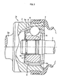
Fig. 2 is a longitudinal cross-sectional view of a DOJ in a drive axle inFig. 1 ; -
Fig. 3 is a longitudinal cross-sectional view of a UJ in the drive axle inFig. 1 ; and -
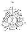
Fig. 4 is an enlarged cross-sectional view of a periphery of a torque transmission ball. - An embodiment of the present invention will be hereinafter described with reference to the drawings.
Fig. 1 shows a drive shaft assembly. The drive shaft assembly includes a constant velocity universal joint J1 on an inboard side, a constant velocity universal joint J2 on an outboard side, and anintermediate axis 1 connecting both joints J1 and J2. The constant velocity universal joint J1 on the inboard side is connected to a differential gear. The constant velocity universal joint J2 on the outboard side is connected to a wheel. The present invention is applied to the constant velocity universal joint J1 on the inboard side. - The constant velocity universal joint J1 on the inboard side is made from a double-offset type constant velocity universal joint (DOJ). As shown in
Fig. 2 , the DOJ includes anouter ring 12, aninner ring 13, sixtorque transmission balls 14, and acage 15. Sixlinear ball grooves 12b are formed in an axial direction on a cylindrical innercircumferential surface 12a of theouter ring 12. Sixlinear ball grooves 13b are formed in the axial direction on a spherical outercircumferential surface 13a of theinner ring 13. Thetorque transmission balls 14 are disposed on a ball track formed by a pair composed of theball groove 12b of theouter ring 12 and theball groove 13b of theinner ring 13. Thecage 15 holds thetorque transmission balls 14. Astem section 12c of theouter ring 12 is connected to a differential gear. Theintermediate axis 1 is connected to a connecting hole in a center section of theinner ring 13 by serration or the like. - The
cage 15 is a ring including an outerspherical surface 15a, an innerspherical surface 15b, and sixpockets 15c. The outerspherical surface 15a is in contact with and guided by the innercircumferential surface 12a of theouter ring 12. The innerspherical surface 15b is in contact with and guided by the outercircumferential surface 13a of theinner ring 13. Thepockets 15c house thetorque transmission balls 14. A spherical center OC0 of the outerspherical surface 15a and a spherical center OC1 of the innerspherical surface 15b are each offset to opposite sides of a joint center O by an equal distance in the axial direction. - When the joint transmits torque while at an operating angle, the
cage 15 rotates with thetorque transmission balls 14 that move on the ball tracks in adherence to tilting of theinner ring 13 and holds thetorque transmission balls 14 at an angle bisecting plane of the operating angle. As a result, constant velocity of the joint can be maintained. When theouter ring 12 and theinner ring 13 move in relative movement in the axial direction, sliding occurs between the outerspherical surface 15a of thecage 15 and the innercircumferential surface 12a of theouter ring 12, making possible a smooth axial movement (plunging). - The constant velocity universal joint J2 on the outboard side is made from an undercut-free type constant velocity universal joint (UJ).
Fig. 3 shows an example of a state in which an operating angle θ of the undercut-free type constant velocity universal joint is 0°. The constant velocity universal joint J2 includes anouter ring 2, aninner ring 4, eighttorque transmission balls 6, and acage 8. Eight curved-bottom ball grooves 3 are formed on a spherical innercircumferential surface 2a of theouter ring 2. Eight curved-bottom ball grooves 5 are formed on a spherical outercircumferential surface 4a of theinner ring 4. Thetorque transmission balls 6 are each disposed on each ball track formed by theball grooves 3 and 5 of the inner and outer rings. Thecage 8 is interpositioned between the inner and outer rings, and respectively stores and holds eachtorque transmission ball 6 in eightpockets 7. The intermediate axis 1 (seeFig. 1 ) of the drive shaft is connected to an inner circumference of theinner ring 4 via aspline 4c. A wheel side component is connected to asystem section 2x of theouter ring 2. - The
ball grooves balls 14 make an angular contact with theball grooves balls 14 to bothball grooves outer ring 12 and theinner ring 13 is 30° to 35°, as shown inFig. 4 . - The contact angle of a conventional ball groove is set within a range of 35° to 40°. Therefore, compared to a ball groove in which the contact angle is 30° to 35°, an operating angle until a longitudinal axis side edge section of a contact ellipse of the
ball 14 reaches shoulder sections of theball grooves ball grooves cage 15 thickness were required to be significantly increased. In the present invention, as a result of the ball contact angle being a range of 30° to 35°, a high operating angle can be actualized without the depth of theball grooves cage 15 thickness being increased. - Here, "ball contact angle" refers to an angle α between a straight line La and a straight line Lb in
Fig. 4 . The straight line La is a center line in a circumferential direction of theball grooves ball grooves balls 14. - The DOJ of the present invention does not merely have a contact angle of 30° to 35°. When the contact angle is simply 30° to 35°, an increase in ball groove surface pressure occurs and durability deteriorates. Therefore, in addition to the contact angle, interior specifications are modified. Table 1 compares a product of the present invention and an example of a conventional product on five items. In the product of the present invention, it is confirmed that a size reduction of 3% or more can be achieved in the DOJ with six balls compared to the conventional product.
[Table 1] Item Product of Present Invention Conventional Product 1 (Ball dameter) / (Outer ring outer diameter) 0.21~0.25 0.21~0.25 2 (Ball pitch diameter) / (Outer ring outer diameter) 0.64~0.68 0.64~0.68 3 Ball. groove contact angle 30~35° 35~40° 4 Ball groove contact ratio 1.02~1.08 1.04~1.10 5 (Cage offset amount)/ (Ball pitch diameter) 0.07~0.09 0.09~0.11 - As is clear from
Items - In other words, the ball groove surface pressure and the contact ellipse pushing out against the ball groove shoulder section have tendencies shown in Table 2, regarding four items. Based on Table 2, in the present invention, the ball groove contact angle and contact ratio are shifted within the ranges of
Items Items [Table 2] Item Guiding groove surface pressure Pushing out of contact ellipse against guiding groove shoulder section Reduction of ball diameter Increase Contact ellipse becomes smaller and pushing allowance increases Reduction of ball pitch diameter Increase Contact ellipse becomes larger and pushing allowance decreases Reduction of contact angle of ball groove Increase Contact ellipse becomes larger. However, distance to guiding groove shoulder section increases due to reduction of contact angle. Therefore, pushing allowance increases. Increase in conact ratio of ball groove Decrease Contact ellipse becomes larger and pushing allowance increases - At the same time, excessive increase of the offset amount leads to an increase in outer ring outer diameter. This is because, when the cage offset amount increases, when the operating angle is granted, a relative movement amount of the ball to a cage window in the radial direction during a single rotation of the joint increases. Therefore, even at the maximum operating angle, the thickness of the cage is too thick to prevent the ball from leaving the cage pocket. As a result, the outer ring outer diameter increases.
- From the above, the cage offset amount is preferable reduced to minimize the outer ring outer diameter. However, when the cage offset amount is too small, a reduction in operability occurs. Therefore, the product of the present invention is set to the range in Item 5 of Table 1. An optimal range of the cage offset amount changes depending on joint size. Therefore, the optimal range is indicated by a ratio with the ball pitch diameter to eliminate changes among sizes.
- Joint interior specifications are described for achieving a 3% or more size reduction in the six-ball DOJ, compared to the conventional DOJ. However, as a result of all
Items 1 to 5 being applied as a set, a DOJ having the same strength and durability as the conventional product can be established. - The present invention can have a high operating angle of 30° or more and can achieve reduction in weight and size by a drive shift assembly in which the fixed-constant velocity universal joint having eight balls is disposed on the outboard side and the slide-type constant velocity universal joint of the present invention is disposed on the inboard side.
Claims (3)
- A slide-type constant velocity universal joint comprising: an outer ring in which six linear ball grooves are formed on a cylindrical inner circumferential surface in an axial direction, an inner ring on which six linear ball grooves are formed on a spherical outer circumferential surface in the axial direction and a connecting hole for connecting a shaft is formed in a center section, six torque transmission balls disposed on ball tracks formed by a pair composed of the a ball groove on the outer ring and a ball groove on the inner ring, and a cage having pockets for storing the torque transmission balls, a convex spherical outer circumferential surface that is in contact with and guided by the inner circumferential surface of the outer ring, and a concave spherical inner circumferential surface that is in contact with and guided by the outer circumferential surface of the inner ring and in which a spherical surface center of the outer circumferential surface and a spherical surface center of the inner circumferential surface are offset to opposite sides of a pocket center in the axial direction, wherein
a ratio of ball diameter to outer ring outer diameter is 0.21 to 0.25,
a ratio of ball pitch diameter to outer ring outer diameter is 0.64 to 0.68,
a contact angle of the ball groove is 30° to 35°,
a contact ratio of the ball groove is 1.02 to 1.08, and
a ratio of cage offset amount to ball pitch diameter is 0.07 to 0.09. - The slide-type constant velocity universal joint according to claim 1, wherein a maximum operating angle is 30° or more.
- A drive shaft comprising a fixed-constant velocity universal joint having eight torque transmission balls on an outboard side and comprising the slide-type constant velocity universal joint according to claim 1 or 2 on an inboard side.
Applications Claiming Priority (2)
| Application Number | Priority Date | Filing Date | Title |
|---|---|---|---|
| JP2005276498A JP5073190B2 (en) | 2005-09-22 | 2005-09-22 | Sliding constant velocity universal joint |
| PCT/JP2006/318501 WO2007034776A1 (en) | 2005-09-22 | 2006-09-19 | Sliding-type constant velocity universal joint |
Publications (3)
| Publication Number | Publication Date |
|---|---|
| EP1927775A1 true EP1927775A1 (en) | 2008-06-04 |
| EP1927775A4 EP1927775A4 (en) | 2009-09-09 |
| EP1927775B1 EP1927775B1 (en) | 2015-08-19 |
Family
ID=37888819
Family Applications (1)
| Application Number | Title | Priority Date | Filing Date |
|---|---|---|---|
| EP06810243.3A Active EP1927775B1 (en) | 2005-09-22 | 2006-09-19 | Sliding-type constant velocity universal joint |
Country Status (5)
| Country | Link |
|---|---|
| US (1) | US8079913B2 (en) |
| EP (1) | EP1927775B1 (en) |
| JP (1) | JP5073190B2 (en) |
| CN (1) | CN101268294B (en) |
| WO (1) | WO2007034776A1 (en) |
Cited By (2)
| Publication number | Priority date | Publication date | Assignee | Title |
|---|---|---|---|---|
| WO2010045967A1 (en) * | 2008-10-21 | 2010-04-29 | Gkn Driveline Deutschland Gmbh | Cage having a specific surface hardness for a constant-velocity rotary ball joint |
| DE202014003168U1 (en) | 2014-04-12 | 2014-05-13 | Gkn Driveline Deutschland Gmbh | Constant velocity joint, drive shaft and drive train arrangement |
Families Citing this family (13)
| Publication number | Priority date | Publication date | Assignee | Title |
|---|---|---|---|---|
| JP2010255647A (en) * | 2009-04-21 | 2010-11-11 | Ntn Corp | Cross groove-type constant velocity universal joint |
| US8684850B2 (en) * | 2010-04-02 | 2014-04-01 | Ntn Corporation | Constant velocity universal joint |
| CN102248101A (en) * | 2011-06-15 | 2011-11-23 | 江苏创一精锻有限公司 | Whole forging near net forming process for inner ball cage sliding sleeve |
| JP6165497B2 (en) * | 2012-08-03 | 2017-07-19 | Ntn株式会社 | Cage universal joint cage, fixed type constant velocity universal joint incorporating the same, and drive shaft incorporating the fixed type constant velocity universal joint |
| CN103216540A (en) * | 2013-04-01 | 2013-07-24 | 浙江欧迪恩传动科技股份有限公司 | Rzeppa universal joint with double pressure angles |
| JP6808531B2 (en) * | 2017-02-16 | 2021-01-06 | Ntn株式会社 | Sliding constant velocity universal joint |
| CN108843759A (en) * | 2018-09-11 | 2018-11-20 | 李桂君 | A kind of Eccentrically rocking type reduction gear |
| JP7458712B2 (en) * | 2019-04-05 | 2024-04-01 | Ntn株式会社 | Fixed constant velocity universal joint |
| JP2023032205A (en) | 2021-08-26 | 2023-03-09 | Ntn株式会社 | Sliding constant velocity universal joint |
| JP7599456B2 (en) | 2022-06-16 | 2024-12-13 | Ntn株式会社 | Sliding constant velocity joint |
| CN115585197A (en) * | 2022-11-08 | 2023-01-10 | 浙江向隆机械有限公司 | A ball cage type universal joint with large working angle |
| CN121358967A (en) | 2023-07-26 | 2026-01-16 | Ntn株式会社 | Sliding constant velocity universal coupling |
| JP2025034018A (en) | 2023-08-30 | 2025-03-13 | Ntn株式会社 | Sliding constant velocity universal joint and wheel drive device equipped with same |
Family Cites Families (21)
| Publication number | Priority date | Publication date | Assignee | Title |
|---|---|---|---|---|
| US4020650A (en) * | 1976-01-12 | 1977-05-03 | Lohr & Bromkamp Gmbh | Constant velocity universal joint and ball grooves therefor |
| JPS6157233A (en) | 1984-08-28 | 1986-03-24 | Mitsubishi Heavy Ind Ltd | Reactor |
| JPH0140336Y2 (en) | 1984-09-20 | 1989-12-04 | ||
| JPH03105725A (en) | 1989-09-19 | 1991-05-02 | Ricoh Co Ltd | optical recording device |
| JP2514956Y2 (en) | 1990-02-19 | 1996-10-23 | エヌティエヌ株式会社 | Constant velocity joint |
| JPH0678127B2 (en) | 1990-09-04 | 1994-10-05 | 日立機電工業株式会社 | Sorting method in article sorting apparatus |
| JP2565675Y2 (en) | 1991-03-29 | 1998-03-18 | エヌティエヌ株式会社 | Constant velocity joint |
| JP3105725B2 (en) | 1993-12-27 | 2000-11-06 | 株式会社日本コンラックス | Banknote recognition device |
| JP3859295B2 (en) * | 1996-06-28 | 2006-12-20 | Ntn株式会社 | Sliding type constant velocity universal joint |
| EP0950824A3 (en) * | 1998-04-15 | 2000-02-02 | Nsk Ltd | Constant velocity joint and rolling bearing unit for wheel |
| FR2792045B1 (en) | 1999-04-06 | 2001-06-29 | Gkn Glaenzer Spicer | HOMOCINETIC BALL JOINT |
| JP2000314430A (en) * | 1999-04-28 | 2000-11-14 | Ntn Corp | Sliding type constant velocity universal joint for propeller shaft |
| JP4048008B2 (en) * | 1999-09-30 | 2008-02-13 | Ntn株式会社 | ATV drive axle |
| JP3469878B2 (en) * | 2000-02-16 | 2003-11-25 | デルファイ・テクノロジーズ・インコーポレーテッド | Constant speed stroke joint |
| JP2002310180A (en) * | 2001-04-09 | 2002-10-23 | Ntn Corp | Constant velocity universal joint |
| US6913540B2 (en) * | 2001-05-10 | 2005-07-05 | Ntn Corporation | Constant velocity universal joint for propeller shaft |
| US6817950B2 (en) * | 2002-11-14 | 2004-11-16 | Gkn Driveline North America, Inc. | High angle constant velocity joint |
| JP4223358B2 (en) * | 2003-09-04 | 2009-02-12 | Ntn株式会社 | Fixed constant velocity universal joint |
| JP2005188620A (en) * | 2003-12-25 | 2005-07-14 | Ntn Corp | Stationary type constant velocity universal joint |
| JP2005226778A (en) * | 2004-02-13 | 2005-08-25 | Ntn Corp | Constant velocity universal joint |
| JP4116018B2 (en) | 2005-05-31 | 2008-07-09 | 京セラミタ株式会社 | Image processing device |
-
2005
- 2005-09-22 JP JP2005276498A patent/JP5073190B2/en not_active Expired - Lifetime
-
2006
- 2006-09-19 CN CN200680034381.9A patent/CN101268294B/en active Active
- 2006-09-19 EP EP06810243.3A patent/EP1927775B1/en active Active
- 2006-09-19 WO PCT/JP2006/318501 patent/WO2007034776A1/en not_active Ceased
- 2006-09-19 US US11/992,191 patent/US8079913B2/en active Active
Cited By (2)
| Publication number | Priority date | Publication date | Assignee | Title |
|---|---|---|---|---|
| WO2010045967A1 (en) * | 2008-10-21 | 2010-04-29 | Gkn Driveline Deutschland Gmbh | Cage having a specific surface hardness for a constant-velocity rotary ball joint |
| DE202014003168U1 (en) | 2014-04-12 | 2014-05-13 | Gkn Driveline Deutschland Gmbh | Constant velocity joint, drive shaft and drive train arrangement |
Also Published As
| Publication number | Publication date |
|---|---|
| WO2007034776A1 (en) | 2007-03-29 |
| JP5073190B2 (en) | 2012-11-14 |
| JP2007085488A (en) | 2007-04-05 |
| EP1927775A4 (en) | 2009-09-09 |
| US20090136287A1 (en) | 2009-05-28 |
| CN101268294B (en) | 2010-09-29 |
| CN101268294A (en) | 2008-09-17 |
| EP1927775B1 (en) | 2015-08-19 |
| US8079913B2 (en) | 2011-12-20 |
Similar Documents
| Publication | Publication Date | Title |
|---|---|---|
| EP1927775B1 (en) | Sliding-type constant velocity universal joint | |
| KR100556574B1 (en) | Sliding Constant Velocity Universal Joint | |
| US8998729B2 (en) | Fixed-type constant velocity universal joint | |
| EP3015731B1 (en) | Fixed-type constant velocity universal joint | |
| US8292749B2 (en) | Fixed type constant velocity universal joint | |
| JP2012017809A5 (en) | ||
| EP1770298B1 (en) | Fixed type constant velocity universal joint | |
| US6910970B2 (en) | Constant velocity universal joint | |
| US7951009B2 (en) | Fixed constant-velocity universal joint | |
| US20240052893A1 (en) | Plunging type constant velocity universal joint for propeller shaft | |
| US11371564B2 (en) | Plunging type constant velocity universal joint | |
| EP2372180A1 (en) | Fixed constant velocity universal joint | |
| EP1557579B1 (en) | Sliding type constant velocity universal joint | |
| JP4681235B2 (en) | Constant velocity joint | |
| JP5355876B2 (en) | Constant velocity universal joint | |
| WO2024127915A1 (en) | Fixed-type universal joint | |
| JP2009079684A (en) | Fixed type constant velocity universal joint | |
| US20240044376A1 (en) | Constant velocity joint | |
| US20240426349A1 (en) | Plunging type constant velocity universal joint | |
| US20250003455A1 (en) | Constant-velocity slip ball joint | |
| JP2023161283A (en) | Sliding type constant velocity universal joint | |
| JP2007271040A (en) | Fixed type constant velocity universal joint |
Legal Events
| Date | Code | Title | Description |
|---|---|---|---|
| PUAI | Public reference made under article 153(3) epc to a published international application that has entered the european phase |
Free format text: ORIGINAL CODE: 0009012 |
|
| 17P | Request for examination filed |
Effective date: 20080313 |
|
| AK | Designated contracting states |
Kind code of ref document: A1 Designated state(s): AT BE BG CH CY CZ DE DK EE ES FI FR GB GR HU IE IS IT LI LT LU LV MC NL PL PT RO SE SI SK TR |
|
| A4 | Supplementary search report drawn up and despatched |
Effective date: 20090811 |
|
| RIC1 | Information provided on ipc code assigned before grant |
Ipc: F16D 3/227 20060101AFI20070529BHEP Ipc: F16D 3/224 20060101ALI20090805BHEP |
|
| 17Q | First examination report despatched |
Effective date: 20091109 |
|
| DAX | Request for extension of the european patent (deleted) | ||
| GRAP | Despatch of communication of intention to grant a patent |
Free format text: ORIGINAL CODE: EPIDOSNIGR1 |
|
| INTG | Intention to grant announced |
Effective date: 20150320 |
|
| GRAS | Grant fee paid |
Free format text: ORIGINAL CODE: EPIDOSNIGR3 |
|
| GRAA | (expected) grant |
Free format text: ORIGINAL CODE: 0009210 |
|
| AK | Designated contracting states |
Kind code of ref document: B1 Designated state(s): AT BE BG CH CY CZ DE DK EE ES FI FR GB GR HU IE IS IT LI LT LU LV MC NL PL PT RO SE SI SK TR |
|
| REG | Reference to a national code |
Ref country code: GB Ref legal event code: FG4D |
|
| REG | Reference to a national code |
Ref country code: CH Ref legal event code: EP |
|
| REG | Reference to a national code |
Ref country code: IE Ref legal event code: FG4D |
|
| REG | Reference to a national code |
Ref country code: AT Ref legal event code: REF Ref document number: 744044 Country of ref document: AT Kind code of ref document: T Effective date: 20150915 |
|
| REG | Reference to a national code |
Ref country code: DE Ref legal event code: R096 Ref document number: 602006046365 Country of ref document: DE |
|
| REG | Reference to a national code |
Ref country code: AT Ref legal event code: MK05 Ref document number: 744044 Country of ref document: AT Kind code of ref document: T Effective date: 20150819 |
|
| REG | Reference to a national code |
Ref country code: LT Ref legal event code: MG4D |
|
| REG | Reference to a national code |
Ref country code: NL Ref legal event code: MP Effective date: 20150819 |
|
| PG25 | Lapsed in a contracting state [announced via postgrant information from national office to epo] |
Ref country code: LV Free format text: LAPSE BECAUSE OF FAILURE TO SUBMIT A TRANSLATION OF THE DESCRIPTION OR TO PAY THE FEE WITHIN THE PRESCRIBED TIME-LIMIT Effective date: 20150819 Ref country code: GR Free format text: LAPSE BECAUSE OF FAILURE TO SUBMIT A TRANSLATION OF THE DESCRIPTION OR TO PAY THE FEE WITHIN THE PRESCRIBED TIME-LIMIT Effective date: 20151120 Ref country code: FI Free format text: LAPSE BECAUSE OF FAILURE TO SUBMIT A TRANSLATION OF THE DESCRIPTION OR TO PAY THE FEE WITHIN THE PRESCRIBED TIME-LIMIT Effective date: 20150819 Ref country code: LT Free format text: LAPSE BECAUSE OF FAILURE TO SUBMIT A TRANSLATION OF THE DESCRIPTION OR TO PAY THE FEE WITHIN THE PRESCRIBED TIME-LIMIT Effective date: 20150819 |
|
| PG25 | Lapsed in a contracting state [announced via postgrant information from national office to epo] |
Ref country code: PL Free format text: LAPSE BECAUSE OF FAILURE TO SUBMIT A TRANSLATION OF THE DESCRIPTION OR TO PAY THE FEE WITHIN THE PRESCRIBED TIME-LIMIT Effective date: 20150819 Ref country code: AT Free format text: LAPSE BECAUSE OF FAILURE TO SUBMIT A TRANSLATION OF THE DESCRIPTION OR TO PAY THE FEE WITHIN THE PRESCRIBED TIME-LIMIT Effective date: 20150819 Ref country code: IS Free format text: LAPSE BECAUSE OF FAILURE TO SUBMIT A TRANSLATION OF THE DESCRIPTION OR TO PAY THE FEE WITHIN THE PRESCRIBED TIME-LIMIT Effective date: 20151219 Ref country code: PT Free format text: LAPSE BECAUSE OF FAILURE TO SUBMIT A TRANSLATION OF THE DESCRIPTION OR TO PAY THE FEE WITHIN THE PRESCRIBED TIME-LIMIT Effective date: 20151221 Ref country code: SE Free format text: LAPSE BECAUSE OF FAILURE TO SUBMIT A TRANSLATION OF THE DESCRIPTION OR TO PAY THE FEE WITHIN THE PRESCRIBED TIME-LIMIT Effective date: 20150819 Ref country code: ES Free format text: LAPSE BECAUSE OF FAILURE TO SUBMIT A TRANSLATION OF THE DESCRIPTION OR TO PAY THE FEE WITHIN THE PRESCRIBED TIME-LIMIT Effective date: 20150819 |
|
| PG25 | Lapsed in a contracting state [announced via postgrant information from national office to epo] |
Ref country code: NL Free format text: LAPSE BECAUSE OF FAILURE TO SUBMIT A TRANSLATION OF THE DESCRIPTION OR TO PAY THE FEE WITHIN THE PRESCRIBED TIME-LIMIT Effective date: 20150819 |
|
| PG25 | Lapsed in a contracting state [announced via postgrant information from national office to epo] |
Ref country code: SK Free format text: LAPSE BECAUSE OF FAILURE TO SUBMIT A TRANSLATION OF THE DESCRIPTION OR TO PAY THE FEE WITHIN THE PRESCRIBED TIME-LIMIT Effective date: 20150819 Ref country code: CZ Free format text: LAPSE BECAUSE OF FAILURE TO SUBMIT A TRANSLATION OF THE DESCRIPTION OR TO PAY THE FEE WITHIN THE PRESCRIBED TIME-LIMIT Effective date: 20150819 Ref country code: IT Free format text: LAPSE BECAUSE OF FAILURE TO SUBMIT A TRANSLATION OF THE DESCRIPTION OR TO PAY THE FEE WITHIN THE PRESCRIBED TIME-LIMIT Effective date: 20150819 Ref country code: EE Free format text: LAPSE BECAUSE OF FAILURE TO SUBMIT A TRANSLATION OF THE DESCRIPTION OR TO PAY THE FEE WITHIN THE PRESCRIBED TIME-LIMIT Effective date: 20150819 Ref country code: DK Free format text: LAPSE BECAUSE OF FAILURE TO SUBMIT A TRANSLATION OF THE DESCRIPTION OR TO PAY THE FEE WITHIN THE PRESCRIBED TIME-LIMIT Effective date: 20150819 |
|
| REG | Reference to a national code |
Ref country code: CH Ref legal event code: PL |
|
| REG | Reference to a national code |
Ref country code: DE Ref legal event code: R097 Ref document number: 602006046365 Country of ref document: DE |
|
| PG25 | Lapsed in a contracting state [announced via postgrant information from national office to epo] |
Ref country code: MC Free format text: LAPSE BECAUSE OF FAILURE TO SUBMIT A TRANSLATION OF THE DESCRIPTION OR TO PAY THE FEE WITHIN THE PRESCRIBED TIME-LIMIT Effective date: 20150819 Ref country code: RO Free format text: LAPSE BECAUSE OF FAILURE TO SUBMIT A TRANSLATION OF THE DESCRIPTION OR TO PAY THE FEE WITHIN THE PRESCRIBED TIME-LIMIT Effective date: 20150819 |
|
| PLBE | No opposition filed within time limit |
Free format text: ORIGINAL CODE: 0009261 |
|
| STAA | Information on the status of an ep patent application or granted ep patent |
Free format text: STATUS: NO OPPOSITION FILED WITHIN TIME LIMIT |
|
| REG | Reference to a national code |
Ref country code: IE Ref legal event code: MM4A |
|
| 26N | No opposition filed |
Effective date: 20160520 |
|
| GBPC | Gb: european patent ceased through non-payment of renewal fee |
Effective date: 20151119 |
|
| PG25 | Lapsed in a contracting state [announced via postgrant information from national office to epo] |
Ref country code: CH Free format text: LAPSE BECAUSE OF NON-PAYMENT OF DUE FEES Effective date: 20150930 Ref country code: IE Free format text: LAPSE BECAUSE OF NON-PAYMENT OF DUE FEES Effective date: 20150919 Ref country code: LI Free format text: LAPSE BECAUSE OF NON-PAYMENT OF DUE FEES Effective date: 20150930 |
|
| REG | Reference to a national code |
Ref country code: FR Ref legal event code: PLFP Year of fee payment: 11 |
|
| PG25 | Lapsed in a contracting state [announced via postgrant information from national office to epo] |
Ref country code: SI Free format text: LAPSE BECAUSE OF FAILURE TO SUBMIT A TRANSLATION OF THE DESCRIPTION OR TO PAY THE FEE WITHIN THE PRESCRIBED TIME-LIMIT Effective date: 20150819 |
|
| PG25 | Lapsed in a contracting state [announced via postgrant information from national office to epo] |
Ref country code: GB Free format text: LAPSE BECAUSE OF NON-PAYMENT OF DUE FEES Effective date: 20151119 |
|
| PG25 | Lapsed in a contracting state [announced via postgrant information from national office to epo] |
Ref country code: BE Free format text: LAPSE BECAUSE OF FAILURE TO SUBMIT A TRANSLATION OF THE DESCRIPTION OR TO PAY THE FEE WITHIN THE PRESCRIBED TIME-LIMIT Effective date: 20150819 |
|
| PG25 | Lapsed in a contracting state [announced via postgrant information from national office to epo] |
Ref country code: HU Free format text: LAPSE BECAUSE OF FAILURE TO SUBMIT A TRANSLATION OF THE DESCRIPTION OR TO PAY THE FEE WITHIN THE PRESCRIBED TIME-LIMIT; INVALID AB INITIO Effective date: 20060919 Ref country code: BG Free format text: LAPSE BECAUSE OF FAILURE TO SUBMIT A TRANSLATION OF THE DESCRIPTION OR TO PAY THE FEE WITHIN THE PRESCRIBED TIME-LIMIT Effective date: 20150819 |
|
| PG25 | Lapsed in a contracting state [announced via postgrant information from national office to epo] |
Ref country code: CY Free format text: LAPSE BECAUSE OF FAILURE TO SUBMIT A TRANSLATION OF THE DESCRIPTION OR TO PAY THE FEE WITHIN THE PRESCRIBED TIME-LIMIT Effective date: 20150819 |
|
| REG | Reference to a national code |
Ref country code: FR Ref legal event code: PLFP Year of fee payment: 12 |
|
| PG25 | Lapsed in a contracting state [announced via postgrant information from national office to epo] |
Ref country code: TR Free format text: LAPSE BECAUSE OF FAILURE TO SUBMIT A TRANSLATION OF THE DESCRIPTION OR TO PAY THE FEE WITHIN THE PRESCRIBED TIME-LIMIT Effective date: 20150819 |
|
| PG25 | Lapsed in a contracting state [announced via postgrant information from national office to epo] |
Ref country code: LU Free format text: LAPSE BECAUSE OF NON-PAYMENT OF DUE FEES Effective date: 20150919 |
|
| REG | Reference to a national code |
Ref country code: FR Ref legal event code: PLFP Year of fee payment: 13 |
|
| PGFP | Annual fee paid to national office [announced via postgrant information from national office to epo] |
Ref country code: DE Payment date: 20250730 Year of fee payment: 20 |
|
| PGFP | Annual fee paid to national office [announced via postgrant information from national office to epo] |
Ref country code: FR Payment date: 20250808 Year of fee payment: 20 |