EP1927724A2 - Turbomachine blade - Google Patents
Turbomachine blade Download PDFInfo
- Publication number
- EP1927724A2 EP1927724A2 EP07120051A EP07120051A EP1927724A2 EP 1927724 A2 EP1927724 A2 EP 1927724A2 EP 07120051 A EP07120051 A EP 07120051A EP 07120051 A EP07120051 A EP 07120051A EP 1927724 A2 EP1927724 A2 EP 1927724A2
- Authority
- EP
- European Patent Office
- Prior art keywords
- blade
- skeleton line
- skeleton
- chord length
- lower limit
- Prior art date
- Legal status (The legal status is an assumption and is not a legal conclusion. Google has not performed a legal analysis and makes no representation as to the accuracy of the status listed.)
- Granted
Links
Images

Classifications
-
- F—MECHANICAL ENGINEERING; LIGHTING; HEATING; WEAPONS; BLASTING
- F01—MACHINES OR ENGINES IN GENERAL; ENGINE PLANTS IN GENERAL; STEAM ENGINES
- F01D—NON-POSITIVE DISPLACEMENT MACHINES OR ENGINES, e.g. STEAM TURBINES
- F01D5/00—Blades; Blade-carrying members; Heating, heat-insulating, cooling or antivibration means on the blades or the members
- F01D5/12—Blades
- F01D5/14—Form or construction
- F01D5/141—Shape, i.e. outer, aerodynamic form
-
- F—MECHANICAL ENGINEERING; LIGHTING; HEATING; WEAPONS; BLASTING
- F01—MACHINES OR ENGINES IN GENERAL; ENGINE PLANTS IN GENERAL; STEAM ENGINES
- F01D—NON-POSITIVE DISPLACEMENT MACHINES OR ENGINES, e.g. STEAM TURBINES
- F01D9/00—Stators
- F01D9/02—Nozzles; Nozzle boxes; Stator blades; Guide conduits, e.g. individual nozzles
- F01D9/04—Nozzles; Nozzle boxes; Stator blades; Guide conduits, e.g. individual nozzles forming ring or sector
- F01D9/041—Nozzles; Nozzle boxes; Stator blades; Guide conduits, e.g. individual nozzles forming ring or sector using blades
-
- F—MECHANICAL ENGINEERING; LIGHTING; HEATING; WEAPONS; BLASTING
- F04—POSITIVE - DISPLACEMENT MACHINES FOR LIQUIDS; PUMPS FOR LIQUIDS OR ELASTIC FLUIDS
- F04D—NON-POSITIVE-DISPLACEMENT PUMPS
- F04D29/00—Details, component parts, or accessories
- F04D29/26—Rotors specially for elastic fluids
- F04D29/32—Rotors specially for elastic fluids for axial flow pumps
- F04D29/321—Rotors specially for elastic fluids for axial flow pumps for axial flow compressors
- F04D29/324—Blades
-
- F—MECHANICAL ENGINEERING; LIGHTING; HEATING; WEAPONS; BLASTING
- F05—INDEXING SCHEMES RELATING TO ENGINES OR PUMPS IN VARIOUS SUBCLASSES OF CLASSES F01-F04
- F05D—INDEXING SCHEME FOR ASPECTS RELATING TO NON-POSITIVE-DISPLACEMENT MACHINES OR ENGINES, GAS-TURBINES OR JET-PROPULSION PLANTS
- F05D2250/00—Geometry
- F05D2250/70—Shape
- F05D2250/74—Shape given by a set or table of xyz-coordinates
-
- Y—GENERAL TAGGING OF NEW TECHNOLOGICAL DEVELOPMENTS; GENERAL TAGGING OF CROSS-SECTIONAL TECHNOLOGIES SPANNING OVER SEVERAL SECTIONS OF THE IPC; TECHNICAL SUBJECTS COVERED BY FORMER USPC CROSS-REFERENCE ART COLLECTIONS [XRACs] AND DIGESTS
- Y10—TECHNICAL SUBJECTS COVERED BY FORMER USPC
- Y10S—TECHNICAL SUBJECTS COVERED BY FORMER USPC CROSS-REFERENCE ART COLLECTIONS [XRACs] AND DIGESTS
- Y10S416/00—Fluid reaction surfaces, i.e. impellers
- Y10S416/02—Formulas of curves
-
- Y—GENERAL TAGGING OF NEW TECHNOLOGICAL DEVELOPMENTS; GENERAL TAGGING OF CROSS-SECTIONAL TECHNOLOGIES SPANNING OVER SEVERAL SECTIONS OF THE IPC; TECHNICAL SUBJECTS COVERED BY FORMER USPC CROSS-REFERENCE ART COLLECTIONS [XRACs] AND DIGESTS
- Y10—TECHNICAL SUBJECTS COVERED BY FORMER USPC
- Y10S—TECHNICAL SUBJECTS COVERED BY FORMER USPC CROSS-REFERENCE ART COLLECTIONS [XRACs] AND DIGESTS
- Y10S416/00—Fluid reaction surfaces, i.e. impellers
- Y10S416/05—Variable camber or chord length
Definitions
- the invention relates to the airfoil design of the blades and vanes of a turbomachine, in particular a gas turbine engine, defined by the progression of the skeletal line defined by the skeletal line angle over the chord length and blade height, and the leading edge profile and the blade tip terminating at an air gap.
- the blade of engine blades is composed under the aspect of a fluidically optimal shape design of a plurality of over the blade blade height threaded individual profiles into a three-dimensional blade shape, the individual profile sections are characterized by a particular skeleton line and a certain material thickness on both sides of the skeleton line.
- the course of the skeleton line representing a center line in the respective profile section is designed for a minimum profile pressure loss and a maximum working range in the respective blade area.
- the object of the invention is to design the airfoil profiles of rotor blades and guide vanes of a turbomachine in such a way that the flow disturbances which occur due to the flow disturbances occurring close to the gap, which lead to power losses, are minimized.
- the gist of the invention is that in a gap-proximate region of up to 30% of the blade height starting from the blade tip, the blade profile cuts are characterized by a specific skeleton line profile defined by the skeleton line angle with respect to the chord length of the blade profile, at which in the vicinity of the gap a uniform pressure distribution along the blade section and thus a stable gap vortex is achieved.
- the uniform load distribution in the near-gap blade area has lower gap losses, that is, an increase in the power and the stability limit or a reduction in the number of blades and thus the weight at a constant power and ultimately the cost.
- the dimensionless skeleton line angles for the inventively optimal skeleton line profile for blade profile cuts that fall within the above-mentioned 30% range are in a certain skeletal line angle distribution range that is in one of the chord length (x-axis, in percent) and the dimensionless skeleton line angle ( y-axis) formed coordinate system is arranged, wherein the upper and the lower limit curve of the skeleton line angle distribution are determined by the equations given in claim 1.
- the dimensionless skeleton line angle results from the relationship given in claim 2.
- skeleton lines or the corresponding skeleton line angles in the blade profile sections close to the gap lie within the limits defined by the limit curves, the disturbances and losses caused by the gap are greatly reduced.
- the formation of the skeleton lines according to the invention is not limited to certain leading edge profiles of the blades.
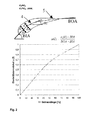
- Fig. 1 shows a side view of an airfoil 1 with swept course of the leading edge 2 of a blade of the compressor of a gas turbine engine. A plurality of sectional planes distributed over the blade height "h" can be seen. According to the skeleton line 4 (FIG. Fig. 2 ) with in each reference point on both sides of the same material thickness "d" is defined by threading the corresponding blade profile sections 5 in the cutting planes 3, the shape of the airfoil 1.
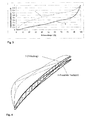
- Fig. 4 are - each with the corresponding schematic pressure load - two blade profile cuts 5 in the near-gap region facing each other, namely of a blade according to the prior art (zigzag line hatching) and of a blade according to the invention (slash-hatching).
- the indicated pressure load is substantially uniform in the blade according to the invention and has the shape of a triangle in the blade according to the prior art, which leads to flow disturbances and losses.
Abstract
Description
Die Erfindung bezieht sich auf das Schaufelblattdesign der Lauf- und Leitschaufeln einer Turbomaschine, insbesondere eines Gasturbinentriebwerks, das durch den Verlauf der durch den Skelettlinienwinkel definierten Skelettlinie über der Sehnenlänge und der Schaufelblatthöhe sowie den Vorderkantenverlauf und die an einem Luftspalt endende Schaufelspitze definiert ist.The invention relates to the airfoil design of the blades and vanes of a turbomachine, in particular a gas turbine engine, defined by the progression of the skeletal line defined by the skeletal line angle over the chord length and blade height, and the leading edge profile and the blade tip terminating at an air gap.
Das Schaufelblatt von Triebwerksschaufeln ist unter dem Aspekt einer strömungstechnisch optimalen Formgestaltung aus einer Vielzahl über die Schaufelblatthöhe aufgefädelter Einzelprofile zu einer dreidimensionalen Schaufelform zusammengesetzt, wobei die einzelnen Profilschnitte durch eine bestimmte Skelettlinie und eine bestimmte Materialstärke beiderseits der Skelettlinie gekennzeichnet sind. Der Verlauf der in dem jeweiligen Profilschnitt eine Mittellinie darstellenden Skelettlinie ist auf einen minimalen Profildruckverlust und einen maximalen Arbeitsbereich in dem jeweiligen Schaufelbereich ausgelegt. Diesen Anforderungen genügen die derzeit eingesetzten CDA-(Controlled Diffusion Airfoil)-Schaufelprofile und deren Derivative im Bereich der Schaufelspitze, das heißt, in dem spaltnahen Schaufelbereich, jedoch nicht,da der strömungstechnisch nachteilige Einfluss des Spaltes zwischen Schaufelspitze und Maschinengehäuse bzw. -nabe bei den heute verwendeten Schaufelformen nicht hinreichend berücksichtigt ist. Durch Umströmung und Überströmung der Schaufelspitze kommt es in diesem Schaufelbereich zur Ausbildung von Wirbeln, die den stabilen Betrieb der Maschine begrenzen und damit zu Strömungs- und Leistungsverlusten, die durch eine - gewichts- und kostenseitig nachteilige - Erhöhung der Anzahl der Schaufeln ausgeglichen werden müssen.The blade of engine blades is composed under the aspect of a fluidically optimal shape design of a plurality of over the blade blade height threaded individual profiles into a three-dimensional blade shape, the individual profile sections are characterized by a particular skeleton line and a certain material thickness on both sides of the skeleton line. The course of the skeleton line representing a center line in the respective profile section is designed for a minimum profile pressure loss and a maximum working range in the respective blade area. These requirements meet the currently used CDA (Controlled Diffusion Airfoil) blade profiles and their derivatives in the blade tip, that is, in the near-gap blade area, but not, since the aerodynamically adverse influence of the gap between the blade tip and the machine housing or hub at The blade shapes used today is not sufficiently considered. By flow around and overflow of the blade tip occurs in this blade area to form vortices that limit the stable operation of the machine and thus flow and power losses caused by a - in terms of weight and cost disadvantageous - increase the number of blades must be compensated.
Der Erfindung liegt die Aufgabe zugrunde, die Schaufelblattprofile von Lauf- und Leitschaufeln einer Turbomaschine so auszubilden, dass die durch die nahe dem Spalt auftretenden Strömungsstörungen, die zu Leistungsverlusten führen, minimiert werden.The object of the invention is to design the airfoil profiles of rotor blades and guide vanes of a turbomachine in such a way that the flow disturbances which occur due to the flow disturbances occurring close to the gap, which lead to power losses, are minimized.
Erfindungsgemäß wird die Aufgabe mit einem Schaufelblattdesign gemäß den Merkmalen des Patentanspruchs 1 gelöst. Vorteilhafte Weiterbildungen der Erfindung sind Gegenstand der Unteransprüche.According to the invention, the object is achieved with an airfoil design according to the features of
Der Kern der Erfindung besteht darin, dass in einem von der Schaufelspitze ausgehenden spaltnahen Bereich von bis zu 30% der Schaufelhöhe die Schaufelprofilschnitte durch einen bestimmten, durch den Skelettlinienwinkel in Bezug auf die Sehnenlänge des Schaufelprofils definierten Skelettlinienverlauf gekennzeichnet sind, bei dem am Spalt bzw. in der Nähe des Spaltes eine gleichmäßige Druckverteilung entlang des Schaufelschnittes und mithin ein stabiler Spaltwirbel erzielt wird. Die gleichmäßige Belastungsverteilung im spaltnahen Schaufelbereich hat geringere Spaltverluste, das heißt, eine Erhöhung der Leistung und der Stabilitätsgrenze bzw. eine Verringerung der Schaufelzahl und damit des Gewichts bei konstanter Leistung und letztlich der Kosten zur Folge.The gist of the invention is that in a gap-proximate region of up to 30% of the blade height starting from the blade tip, the blade profile cuts are characterized by a specific skeleton line profile defined by the skeleton line angle with respect to the chord length of the blade profile, at which in the vicinity of the gap a uniform pressure distribution along the blade section and thus a stable gap vortex is achieved. The uniform load distribution in the near-gap blade area has lower gap losses, that is, an increase in the power and the stability limit or a reduction in the number of blades and thus the weight at a constant power and ultimately the cost.
Die dimensionslosen Skelettlinienwinkel für den erfindungsgemäß optimalen Skelettlinienverlauf, und zwar für Schaufelprofilschnitte, die in den oben erwähnten 30%-Bereich fallen, liegen in einem bestimmten Skelettlinienwinkelverteilungsbereich, der in einem von der Sehnenlänge (x-Achse,in Prozent) und dem dimensionslosen Skelettlinienwinkel (y-Achse) gebildeten Koordinatensystem angeordnet ist, wobei die obere und die untere Grenzkurve der Skelettlinienwinkelverteilung durch die im Anspruch 1 angegebenen Gleichungen bestimmt sind.The dimensionless skeleton line angles for the inventively optimal skeleton line profile for blade profile cuts that fall within the above-mentioned 30% range are in a certain skeletal line angle distribution range that is in one of the chord length (x-axis, in percent) and the dimensionless skeleton line angle ( y-axis) formed coordinate system is arranged, wherein the upper and the lower limit curve of the skeleton line angle distribution are determined by the equations given in
Der dimensionslose Skelettlinienwinkel ergibt sich aus der in Anspruch 2 wiedergegebenen Beziehung.The dimensionless skeleton line angle results from the relationship given in
Sofern die Skelettlinien bzw. die entsprechenden Skelettlinienwinkel in den spaltnahen Schaufelprofilschnitten innerhalb der durch die Grenzkurven festgelegten Grenzen liegen, werden die durch den Spalt verursachten Störungen und Verluste stark vermindert. Die Ausbildung der erfindungsgemäßen Skelettlinien ist nicht auf bestimmte Vorderkantenverläufe der Schaufeln begrenzt.If the skeleton lines or the corresponding skeleton line angles in the blade profile sections close to the gap lie within the limits defined by the limit curves, the disturbances and losses caused by the gap are greatly reduced. The formation of the skeleton lines according to the invention is not limited to certain leading edge profiles of the blades.
Ein Ausführungsbeispiel der Erfindung wird anhand der Zeichnung näher erläutert. Es zeigen:
- Fig. 1
- eine Seitenansicht einer Laufschaufel mit gepfeilter Vorderkante und durch waagerechte Linien angedeuteten Profilschnittebenen;
- Fig. 2
- eine Darstellung eines Schaufelprofils mit Skelettlinie in einem durch die dimensionslose Sehnenlänge (x-Achse) und den dimensionslosen Skelettlinienwinkel (y-Achse) definierten Koordinatensystem;
- Fig. 3
- den von einer oberen und einer unteren Grenzkurve begrenzten Bereich der Skelettlinienwinkelverteilung für einen von der Schaufelspitze ausgehenden begrenzten Schaufelteil; und
- Fig. 4
- eine Gegenüberstellung eines erfindungsgemäß und eines nach dem Stand der Technik ausgebildeten
- Fig. 1
- a side view of a blade with swept leading edge and indicated by horizontal lines profile section planes;
- Fig. 2
- a representation of a blade profile with skeleton line in a coordinate system defined by the dimensionless chord length (x-axis) and the dimensionless skeleton line angle (y-axis);
- Fig. 3
- the area of the skeleton line angle distribution bounded by upper and lower limit curves for a limited blade part emanating from the blade tip; and
- Fig. 4
- a comparison of an inventively and of the prior art trained
Die Skelettlinie 4 in ![]()
worin
- αi (1)
- der jeweilige lokale Winkel bei einem
bestimmten Wert 1x der Sehnenlänge, - BIA
- der Eintrittswinkel und
- BOA
- der Austrittswinkel
wherein
- α i (1)
- the respective local angle at a
certain value 1 x the chord length, - BIA
- the entrance angle and
- BOA
- the exit angle
In einem von der Schaufelspitze 6 ausgehenden Bereich, der etwa 30% der Schaufelblatthöhe "h" umfasst (
Der Skelettlinienwinkel αoG für eine Vielzahl zwischen 0 und 100% liegender Werte lx, das heißt, lx1,lx2 usw., der Sehnenlänge "1" ergibt sich für die obere Grenzkurve 7 aus 
und für die untere Grenzkurve 8 aus 
and for the lower limit curve 8 off
In
- 11
- Schaufelblattairfoil
- 22
- Vorderkanteleading edge
- 33
- Schnittebenencutting planes
- 44
- Skelettlinieskeleton line
- 55
- SchaufelprofilschnittAerofoil section
- 66
- Schaufelspitzeblade tip
- 77
- Obere GrenzkurveUpper limit curve
- 88th
- Untere GrenzkurveLower limit curve
- hH
- Schaufelhöheblade height
- dd
- Materialdickematerial thickness
- α(l)α (l)
- SkelettlinienwinkelSkeleton line angles
- αi α i
- lokaler Skelettlinienwinkellocal skeleton line angle
- ll
- Sehnenlängechord length
- lx l x
- bestimmter Wert der Sehnenlängecertain value of chord length
Claims (3)

ist und für die untere Grenzkurve (8)

ist.An airfoil design for the blades and vanes of a turbomachine, in particular a gas turbine engine, characterized by the progression of the skeleton line (4) defined by the skeletal line angle (α) over the chord length (1) and the leading edge profile and the blade height (h) and at an air gap characterized in that the skeleton line (4) in the blade profile cuts (5), which are in a range of the blade tip (6) outgoing range of up to 30% of the blade height (h) in one extending between upper and lower limit curves (7, 8), wherein the dimensionless skeleton line angle (α) at the respective location (lx) of the chord length (1) for the upper limit curve (7)
is and for the lower limit curve (8)
is.
Applications Claiming Priority (1)
| Application Number | Priority Date | Filing Date | Title |
|---|---|---|---|
| DE102006055869A DE102006055869A1 (en) | 2006-11-23 | 2006-11-23 | Rotor and guide blades designing method for turbo-machine i.e. gas turbine engine, involves running skeleton curve in profile section in sectional line angle distribution area lying between upper and lower limit curves |
Publications (3)
| Publication Number | Publication Date |
|---|---|
| EP1927724A2 true EP1927724A2 (en) | 2008-06-04 |
| EP1927724A3 EP1927724A3 (en) | 2009-05-20 |
| EP1927724B1 EP1927724B1 (en) | 2015-09-09 |
Family
ID=38904754
Family Applications (1)
| Application Number | Title | Priority Date | Filing Date |
|---|---|---|---|
| EP07120051.3A Expired - Fee Related EP1927724B1 (en) | 2006-11-23 | 2007-11-06 | Airfoil |
Country Status (3)
| Country | Link |
|---|---|
| US (1) | US8152473B2 (en) |
| EP (1) | EP1927724B1 (en) |
| DE (1) | DE102006055869A1 (en) |
Cited By (5)
| Publication number | Priority date | Publication date | Assignee | Title |
|---|---|---|---|---|
| WO2013178914A1 (en) * | 2012-05-31 | 2013-12-05 | Snecma | Fan blade for a turbojet of an aircraft having a cambered profile in the foot sections |
| EP2275643A3 (en) * | 2009-07-17 | 2017-10-04 | Rolls-Royce Deutschland Ltd & Co KG | Engine blade with excess front edge loading |
| EP2921648B1 (en) | 2014-03-20 | 2018-12-26 | Ansaldo Energia Switzerland AG | Gas turbine blade comprising bended leading and trailing edges |
| EP3730801A4 (en) * | 2017-12-20 | 2021-05-05 | Ihi Corporation | Fan and compressor stator blade |
| EP3839212A1 (en) * | 2019-12-20 | 2021-06-23 | MTU Aero Engines AG | Turbine blade for a flow engine |
Families Citing this family (38)
| Publication number | Priority date | Publication date | Assignee | Title |
|---|---|---|---|---|
| US8523531B2 (en) * | 2009-12-23 | 2013-09-03 | Alstom Technology Ltd | Airfoil for a compressor blade |
| US9291059B2 (en) * | 2009-12-23 | 2016-03-22 | Alstom Technology Ltd. | Airfoil for a compressor blade |
| DE102010009615B4 (en) | 2010-02-27 | 2016-11-17 | MTU Aero Engines AG | Airfoil with threaded profile cuts |
| DE102010027588A1 (en) * | 2010-07-19 | 2012-01-19 | Rolls-Royce Deutschland Ltd & Co Kg | Fan-Nachleitradschaufel a turbofan engine |
| CN102373971B (en) * | 2010-08-11 | 2014-06-04 | 中国科学院工程热物理研究所 | Integrated pneumatic design method of axial-flow turbine and single-side radial steam/gas discharging system |
| DE102014200644B4 (en) * | 2014-01-16 | 2017-03-02 | MTU Aero Engines AG | Extruded profile and method for producing a blade of a Nachleitrads, blade of a Nachleitrads, Nachleitrad and turbomachinery with such a Nachleitrad |
| EP3985226A1 (en) | 2014-02-19 | 2022-04-20 | Raytheon Technologies Corporation | Gas turbine engine airfoil |
| EP3114321B1 (en) | 2014-02-19 | 2019-04-17 | United Technologies Corporation | Gas turbine engine airfoil |
| EP3108107B1 (en) | 2014-02-19 | 2023-10-11 | Raytheon Technologies Corporation | Turbofan engine with geared architecture and lpc airfoils |
| EP3108100B1 (en) | 2014-02-19 | 2021-04-14 | Raytheon Technologies Corporation | Gas turbine engine fan blade |
| EP3108123B1 (en) | 2014-02-19 | 2023-10-04 | Raytheon Technologies Corporation | Turbofan engine with geared architecture and lpc airfoils |
| US9567858B2 (en) | 2014-02-19 | 2017-02-14 | United Technologies Corporation | Gas turbine engine airfoil |
| US10352331B2 (en) | 2014-02-19 | 2019-07-16 | United Technologies Corporation | Gas turbine engine airfoil |
| EP3108121B1 (en) | 2014-02-19 | 2023-09-06 | Raytheon Technologies Corporation | Turbofan engine with geared architecture and lpc airfoils |
| EP3108110B1 (en) | 2014-02-19 | 2020-04-22 | United Technologies Corporation | Gas turbine engine airfoil |
| WO2015126454A1 (en) | 2014-02-19 | 2015-08-27 | United Technologies Corporation | Gas turbine engine airfoil |
| US10557477B2 (en) | 2014-02-19 | 2020-02-11 | United Technologies Corporation | Gas turbine engine airfoil |
| US9599064B2 (en) | 2014-02-19 | 2017-03-21 | United Technologies Corporation | Gas turbine engine airfoil |
| US10465702B2 (en) | 2014-02-19 | 2019-11-05 | United Technologies Corporation | Gas turbine engine airfoil |
| US10422226B2 (en) | 2014-02-19 | 2019-09-24 | United Technologies Corporation | Gas turbine engine airfoil |
| US10502229B2 (en) | 2014-02-19 | 2019-12-10 | United Technologies Corporation | Gas turbine engine airfoil |
| US10519971B2 (en) | 2014-02-19 | 2019-12-31 | United Technologies Corporation | Gas turbine engine airfoil |
| US9163517B2 (en) | 2014-02-19 | 2015-10-20 | United Technologies Corporation | Gas turbine engine airfoil |
| EP3108106B1 (en) | 2014-02-19 | 2022-05-04 | Raytheon Technologies Corporation | Gas turbine engine airfoil |
| US10570916B2 (en) | 2014-02-19 | 2020-02-25 | United Technologies Corporation | Gas turbine engine airfoil |
| EP3108113A4 (en) | 2014-02-19 | 2017-03-15 | United Technologies Corporation | Gas turbine engine airfoil |
| US10605259B2 (en) | 2014-02-19 | 2020-03-31 | United Technologies Corporation | Gas turbine engine airfoil |
| WO2015126452A1 (en) | 2014-02-19 | 2015-08-27 | United Technologies Corporation | Gas turbine engine airfoil |
| CN105221193B (en) * | 2014-06-12 | 2017-01-25 | 中国科学院工程热物理研究所 | Method for designing axial-flow turbine and single-side radial exhaust steam/gas system |
| JP6468414B2 (en) | 2014-08-12 | 2019-02-13 | 株式会社Ihi | Compressor vane, axial compressor, and gas turbine |
| JP6421091B2 (en) * | 2015-07-30 | 2018-11-07 | 三菱日立パワーシステムズ株式会社 | Axial flow compressor, gas turbine including the same, and stationary blade of axial flow compressor |
| DE102016115868A1 (en) * | 2016-08-26 | 2018-03-01 | Rolls-Royce Deutschland Ltd & Co Kg | High-efficiency fluid flow machine |
| EP3633207A4 (en) * | 2017-05-24 | 2021-06-23 | IHI Corporation | Blade for fan and compressor |
| US10760587B2 (en) | 2017-06-06 | 2020-09-01 | Elliott Company | Extended sculpted twisted return channel vane arrangement |
| US20230051322A1 (en) * | 2019-12-09 | 2023-02-16 | Lg Electronics Inc. | Blower |
| US11286779B2 (en) * | 2020-06-03 | 2022-03-29 | Honeywell International Inc. | Characteristic distribution for rotor blade of booster rotor |
| CN112855284B (en) * | 2021-01-18 | 2022-11-08 | 西北工业大学 | Construction method of low-pressure turbine stator blade wave front edge |
| CN114973902B (en) * | 2022-04-14 | 2023-06-23 | 西北工业大学 | Aeroengine low-pressure turbine model for teaching and assembly method |
Citations (5)
| Publication number | Priority date | Publication date | Assignee | Title |
|---|---|---|---|---|
| EP0661413A1 (en) * | 1993-12-23 | 1995-07-05 | Mtu Motoren- Und Turbinen-Union MàNchen Gmbh | Axial blade cascade with blades of arrowed leading edge |
| EP1186747A2 (en) * | 2000-09-05 | 2002-03-13 | Honda Giken Kogyo Kabushiki Kaisha | An automized blade shape designing method |
| US20040091353A1 (en) * | 2002-09-03 | 2004-05-13 | Shahrokhy Shahpar | Guide vane for a gas turbine engine |
| EP1657401A2 (en) * | 2004-11-12 | 2006-05-17 | Rolls-Royce Deutschland Ltd & Co KG | Turbo machine blade with an extended profile chord length in its tip and root regions |
| US20060210395A1 (en) * | 2004-09-28 | 2006-09-21 | Honeywell International, Inc. | Nonlinearly stacked low noise turbofan stator |
Family Cites Families (10)
| Publication number | Priority date | Publication date | Assignee | Title |
|---|---|---|---|---|
| US4431376A (en) * | 1980-10-27 | 1984-02-14 | United Technologies Corporation | Airfoil shape for arrays of airfoils |
| DE3201436C1 (en) | 1982-01-19 | 1983-04-21 | Kraftwerk Union AG, 4330 Mülheim | Turbomachine blade |
| DE3441115C1 (en) | 1984-11-10 | 1986-01-30 | Daimler-Benz Ag, 7000 Stuttgart | Impeller for a gas turbine |
| GB9119846D0 (en) * | 1991-09-17 | 1991-10-30 | Rolls Royce Plc | Aerofoil members for gas turbine engines and method of making the same |
| JP3082378B2 (en) | 1991-12-20 | 2000-08-28 | 株式会社デンソー | Blower fan |
| ES2212251T3 (en) * | 1998-03-23 | 2004-07-16 | Spal S.R.L. | AXIAL FLOW FAN. |
| GB0003676D0 (en) | 2000-02-17 | 2000-04-05 | Abb Alstom Power Nv | Aerofoils |
| DE102005042115A1 (en) * | 2005-09-05 | 2007-03-08 | Rolls-Royce Deutschland Ltd & Co Kg | Blade of a fluid flow machine with block-defined profile skeleton line |
| CN101326342B (en) * | 2005-10-11 | 2012-06-13 | 阿尔斯通技术有限公司 | Turbo-machine blade |
| DE102005060699A1 (en) * | 2005-12-19 | 2007-06-21 | Rolls-Royce Deutschland Ltd & Co Kg | Turbomachine with adjustable stator |
-
2006
- 2006-11-23 DE DE102006055869A patent/DE102006055869A1/en not_active Withdrawn
-
2007
- 2007-11-06 EP EP07120051.3A patent/EP1927724B1/en not_active Expired - Fee Related
- 2007-11-21 US US11/984,826 patent/US8152473B2/en active Active
Patent Citations (5)
| Publication number | Priority date | Publication date | Assignee | Title |
|---|---|---|---|---|
| EP0661413A1 (en) * | 1993-12-23 | 1995-07-05 | Mtu Motoren- Und Turbinen-Union MàNchen Gmbh | Axial blade cascade with blades of arrowed leading edge |
| EP1186747A2 (en) * | 2000-09-05 | 2002-03-13 | Honda Giken Kogyo Kabushiki Kaisha | An automized blade shape designing method |
| US20040091353A1 (en) * | 2002-09-03 | 2004-05-13 | Shahrokhy Shahpar | Guide vane for a gas turbine engine |
| US20060210395A1 (en) * | 2004-09-28 | 2006-09-21 | Honeywell International, Inc. | Nonlinearly stacked low noise turbofan stator |
| EP1657401A2 (en) * | 2004-11-12 | 2006-05-17 | Rolls-Royce Deutschland Ltd & Co KG | Turbo machine blade with an extended profile chord length in its tip and root regions |
Cited By (9)
| Publication number | Priority date | Publication date | Assignee | Title |
|---|---|---|---|---|
| EP2275643A3 (en) * | 2009-07-17 | 2017-10-04 | Rolls-Royce Deutschland Ltd & Co KG | Engine blade with excess front edge loading |
| WO2013178914A1 (en) * | 2012-05-31 | 2013-12-05 | Snecma | Fan blade for a turbojet of an aircraft having a cambered profile in the foot sections |
| FR2991373A1 (en) * | 2012-05-31 | 2013-12-06 | Snecma | BLOWER DAWN FOR AIRBORNE AIRCRAFT WITH CAMBRE PROFILE IN FOOT SECTIONS |
| US11333164B2 (en) | 2012-05-31 | 2022-05-17 | Safran Aircraft Engines | Airplane turbojet fan blade of cambered profile in its root sections |
| EP2921648B1 (en) | 2014-03-20 | 2018-12-26 | Ansaldo Energia Switzerland AG | Gas turbine blade comprising bended leading and trailing edges |
| EP3730801A4 (en) * | 2017-12-20 | 2021-05-05 | Ihi Corporation | Fan and compressor stator blade |
| US11203945B2 (en) | 2017-12-20 | 2021-12-21 | Ihi Corporation | Stator vane of fan or compressor |
| EP3839212A1 (en) * | 2019-12-20 | 2021-06-23 | MTU Aero Engines AG | Turbine blade for a flow engine |
| WO2021121458A1 (en) * | 2019-12-20 | 2021-06-24 | MTU Aero Engines AG | Guide vane for a turbomachine |
Also Published As
| Publication number | Publication date |
|---|---|
| EP1927724A3 (en) | 2009-05-20 |
| US8152473B2 (en) | 2012-04-10 |
| US20090226322A1 (en) | 2009-09-10 |
| DE102006055869A1 (en) | 2008-05-29 |
| EP1927724B1 (en) | 2015-09-09 |
Similar Documents
| Publication | Publication Date | Title |
|---|---|---|
| EP1927724B1 (en) | Airfoil | |
| EP2473743B1 (en) | Compressor blade for an axial compressor | |
| EP1671030B1 (en) | Rotor blade for a wind power converter | |
| DE3045224C2 (en) | ||
| DE3530769C2 (en) | Blade for a gas turbine engine | |
| EP2626515B1 (en) | Tandem blade group assembly | |
| EP1766192B1 (en) | Vane wheel of a turbine comprising a vane and at least one cooling channel | |
| EP2275643B1 (en) | Engine blade with excess front edge loading | |
| DE112017006296B4 (en) | FLUID DEVICE | |
| DE102006053712A1 (en) | Rotor blade and wind turbine | |
| EP2409002A2 (en) | Tandem blade design | |
| EP0132638A2 (en) | Blade cascade for an axial gas or steam driven turbine | |
| CH659851A5 (en) | TURBINE. | |
| DE1628237A1 (en) | Supersound grille | |
| WO2010149139A2 (en) | Shroud segment to be arranged on a blade | |
| EP0528138A1 (en) | Blade shroud for axial turbine | |
| EP1163425A1 (en) | Turbine blade | |
| DE102006048685A1 (en) | Turbine blade of a gas turbine | |
| EP2226511A2 (en) | Flow working machine with fluid supply | |
| DE102012104240B4 (en) | Hybrid Flow Blade Designs | |
| EP3762587B1 (en) | Airfoil for a turbine blade | |
| EP1288435B1 (en) | Turbine blade with at least one cooling orifice | |
| EP3039246B1 (en) | Turbine blade | |
| EP1865148A2 (en) | Flow machine with rotors with a high specific energy transfer | |
| EP3287640A1 (en) | Fluid flow machine with high performance |
Legal Events
| Date | Code | Title | Description |
|---|---|---|---|
| PUAI | Public reference made under article 153(3) epc to a published international application that has entered the european phase |
Free format text: ORIGINAL CODE: 0009012 |
|
| AK | Designated contracting states |
Kind code of ref document: A2 Designated state(s): AT BE BG CH CY CZ DE DK EE ES FI FR GB GR HU IE IS IT LI LT LU LV MC MT NL PL PT RO SE SI SK TR |
|
| AX | Request for extension of the european patent |
Extension state: AL BA HR MK RS |
|
| PUAL | Search report despatched |
Free format text: ORIGINAL CODE: 0009013 |
|
| AK | Designated contracting states |
Kind code of ref document: A3 Designated state(s): AT BE BG CH CY CZ DE DK EE ES FI FR GB GR HU IE IS IT LI LT LU LV MC MT NL PL PT RO SE SI SK TR |
|
| AX | Request for extension of the european patent |
Extension state: AL BA HR MK RS |
|
| 17P | Request for examination filed |
Effective date: 20090721 |
|
| 17Q | First examination report despatched |
Effective date: 20090820 |
|
| AKX | Designation fees paid |
Designated state(s): DE FR GB |
|
| GRAP | Despatch of communication of intention to grant a patent |
Free format text: ORIGINAL CODE: EPIDOSNIGR1 |
|
| INTG | Intention to grant announced |
Effective date: 20150123 |
|
| GRAS | Grant fee paid |
Free format text: ORIGINAL CODE: EPIDOSNIGR3 |
|
| GRAA | (expected) grant |
Free format text: ORIGINAL CODE: 0009210 |
|
| AK | Designated contracting states |
Kind code of ref document: B1 Designated state(s): DE FR GB |
|
| REG | Reference to a national code |
Ref country code: GB Ref legal event code: FG4D Free format text: NOT ENGLISH |
|
| REG | Reference to a national code |
Ref country code: DE Ref legal event code: R096 Ref document number: 502007014198 Country of ref document: DE |
|
| REG | Reference to a national code |
Ref country code: FR Ref legal event code: PLFP Year of fee payment: 9 |
|
| REG | Reference to a national code |
Ref country code: DE Ref legal event code: R097 Ref document number: 502007014198 Country of ref document: DE |
|
| PLBE | No opposition filed within time limit |
Free format text: ORIGINAL CODE: 0009261 |
|
| STAA | Information on the status of an ep patent application or granted ep patent |
Free format text: STATUS: NO OPPOSITION FILED WITHIN TIME LIMIT |
|
| 26N | No opposition filed |
Effective date: 20160610 |
|
| REG | Reference to a national code |
Ref country code: FR Ref legal event code: PLFP Year of fee payment: 10 |
|
| REG | Reference to a national code |
Ref country code: FR Ref legal event code: PLFP Year of fee payment: 11 |
|
| PGFP | Annual fee paid to national office [announced via postgrant information from national office to epo] |
Ref country code: DE Payment date: 20191127 Year of fee payment: 13 |
|
| PGFP | Annual fee paid to national office [announced via postgrant information from national office to epo] |
Ref country code: FR Payment date: 20191125 Year of fee payment: 13 |
|
| PGFP | Annual fee paid to national office [announced via postgrant information from national office to epo] |
Ref country code: GB Payment date: 20191127 Year of fee payment: 13 |
|
| REG | Reference to a national code |
Ref country code: DE Ref legal event code: R119 Ref document number: 502007014198 Country of ref document: DE |
|
| GBPC | Gb: european patent ceased through non-payment of renewal fee |
Effective date: 20201106 |
|
| PG25 | Lapsed in a contracting state [announced via postgrant information from national office to epo] |
Ref country code: FR Free format text: LAPSE BECAUSE OF NON-PAYMENT OF DUE FEES Effective date: 20201130 |
|
| PG25 | Lapsed in a contracting state [announced via postgrant information from national office to epo] |
Ref country code: GB Free format text: LAPSE BECAUSE OF NON-PAYMENT OF DUE FEES Effective date: 20201106 Ref country code: DE Free format text: LAPSE BECAUSE OF NON-PAYMENT OF DUE FEES Effective date: 20210601 |