EP1927563B1 - Procédé et appareil pour améliorer le rendement de découpe à l'aide d'un profil de mouvement de sortie - Google Patents
Procédé et appareil pour améliorer le rendement de découpe à l'aide d'un profil de mouvement de sortie Download PDFInfo
- Publication number
- EP1927563B1 EP1927563B1 EP20070023126 EP07023126A EP1927563B1 EP 1927563 B1 EP1927563 B1 EP 1927563B1 EP 20070023126 EP20070023126 EP 20070023126 EP 07023126 A EP07023126 A EP 07023126A EP 1927563 B1 EP1927563 B1 EP 1927563B1
- Authority
- EP
- European Patent Office
- Prior art keywords
- sheet
- paper
- nip
- cutter
- downstream
- Prior art date
- Legal status (The legal status is an assumption and is not a legal conclusion. Google has not performed a legal analysis and makes no representation as to the accuracy of the status listed.)
- Active
Links
- 238000000034 method Methods 0.000 title claims description 17
- 238000005520 cutting process Methods 0.000 claims description 14
- 238000011143 downstream manufacturing Methods 0.000 claims description 7
- 238000012538 light obscuration Methods 0.000 description 11
- 239000000463 material Substances 0.000 description 10
- 238000002171 field ion microscopy Methods 0.000 description 9
- 238000012059 flow imaging microscopy Methods 0.000 description 9
- 238000006073 displacement reaction Methods 0.000 description 8
- 238000009825 accumulation Methods 0.000 description 6
- 230000007246 mechanism Effects 0.000 description 4
- 238000000926 separation method Methods 0.000 description 3
- 238000011144 upstream manufacturing Methods 0.000 description 3
- 201000006618 congenital myasthenic syndrome 6 Diseases 0.000 description 2
- 238000013500 data storage Methods 0.000 description 2
- 230000007423 decrease Effects 0.000 description 2
- 238000010586 diagram Methods 0.000 description 2
- 238000003780 insertion Methods 0.000 description 2
- 230000037431 insertion Effects 0.000 description 2
- 238000004519 manufacturing process Methods 0.000 description 2
- 230000008569 process Effects 0.000 description 2
- 101100008046 Caenorhabditis elegans cut-2 gene Proteins 0.000 description 1
- 230000001133 acceleration Effects 0.000 description 1
- 230000005540 biological transmission Effects 0.000 description 1
- 230000008859 change Effects 0.000 description 1
- 230000001419 dependent effect Effects 0.000 description 1
- 230000000694 effects Effects 0.000 description 1
- 230000006870 function Effects 0.000 description 1
- 238000009434 installation Methods 0.000 description 1
- 230000003993 interaction Effects 0.000 description 1
- 230000003287 optical effect Effects 0.000 description 1
- 239000013641 positive control Substances 0.000 description 1
- 238000002360 preparation method Methods 0.000 description 1
- 239000002994 raw material Substances 0.000 description 1
- 238000007789 sealing Methods 0.000 description 1
- 238000011282 treatment Methods 0.000 description 1
- 238000005303 weighing Methods 0.000 description 1
Images


Classifications
-
- B—PERFORMING OPERATIONS; TRANSPORTING
- B65—CONVEYING; PACKING; STORING; HANDLING THIN OR FILAMENTARY MATERIAL
- B65H—HANDLING THIN OR FILAMENTARY MATERIAL, e.g. SHEETS, WEBS, CABLES
- B65H29/00—Delivering or advancing articles from machines; Advancing articles to or into piles
- B65H29/12—Delivering or advancing articles from machines; Advancing articles to or into piles by means of the nip between two, or between two sets of, moving tapes or bands or rollers
-
- B—PERFORMING OPERATIONS; TRANSPORTING
- B65—CONVEYING; PACKING; STORING; HANDLING THIN OR FILAMENTARY MATERIAL
- B65H—HANDLING THIN OR FILAMENTARY MATERIAL, e.g. SHEETS, WEBS, CABLES
- B65H35/00—Delivering articles from cutting or line-perforating machines; Article or web delivery apparatus incorporating cutting or line-perforating devices, e.g. adhesive tape dispensers
- B65H35/04—Delivering articles from cutting or line-perforating machines; Article or web delivery apparatus incorporating cutting or line-perforating devices, e.g. adhesive tape dispensers from or with transverse cutters or perforators
-
- B—PERFORMING OPERATIONS; TRANSPORTING
- B65—CONVEYING; PACKING; STORING; HANDLING THIN OR FILAMENTARY MATERIAL
- B65H—HANDLING THIN OR FILAMENTARY MATERIAL, e.g. SHEETS, WEBS, CABLES
- B65H2301/00—Handling processes for sheets or webs
- B65H2301/40—Type of handling process
- B65H2301/44—Moving, forwarding, guiding material
- B65H2301/445—Moving, forwarding, guiding material stream of articles separated from each other
- B65H2301/4451—Moving, forwarding, guiding material stream of articles separated from each other forming a stream or streams of separated articles
-
- B—PERFORMING OPERATIONS; TRANSPORTING
- B65—CONVEYING; PACKING; STORING; HANDLING THIN OR FILAMENTARY MATERIAL
- B65H—HANDLING THIN OR FILAMENTARY MATERIAL, e.g. SHEETS, WEBS, CABLES
- B65H2513/00—Dynamic entities; Timing aspects
- B65H2513/20—Acceleration or deceleration
-
- B—PERFORMING OPERATIONS; TRANSPORTING
- B65—CONVEYING; PACKING; STORING; HANDLING THIN OR FILAMENTARY MATERIAL
- B65H—HANDLING THIN OR FILAMENTARY MATERIAL, e.g. SHEETS, WEBS, CABLES
- B65H2601/00—Problem to be solved or advantage achieved
- B65H2601/20—Avoiding or preventing undesirable effects
- B65H2601/25—Damages to handled material
- B65H2601/2525—Collisions
-
- Y—GENERAL TAGGING OF NEW TECHNOLOGICAL DEVELOPMENTS; GENERAL TAGGING OF CROSS-SECTIONAL TECHNOLOGIES SPANNING OVER SEVERAL SECTIONS OF THE IPC; TECHNICAL SUBJECTS COVERED BY FORMER USPC CROSS-REFERENCE ART COLLECTIONS [XRACs] AND DIGESTS
- Y10—TECHNICAL SUBJECTS COVERED BY FORMER USPC
- Y10T—TECHNICAL SUBJECTS COVERED BY FORMER US CLASSIFICATION
- Y10T83/00—Cutting
- Y10T83/04—Processes
- Y10T83/0448—With subsequent handling [i.e., of product]
- Y10T83/0462—By accelerating travel
-
- Y—GENERAL TAGGING OF NEW TECHNOLOGICAL DEVELOPMENTS; GENERAL TAGGING OF CROSS-SECTIONAL TECHNOLOGIES SPANNING OVER SEVERAL SECTIONS OF THE IPC; TECHNICAL SUBJECTS COVERED BY FORMER USPC CROSS-REFERENCE ART COLLECTIONS [XRACs] AND DIGESTS
- Y10—TECHNICAL SUBJECTS COVERED BY FORMER USPC
- Y10T—TECHNICAL SUBJECTS COVERED BY FORMER US CLASSIFICATION
- Y10T83/00—Cutting
- Y10T83/202—With product handling means
- Y10T83/2092—Means to move, guide, or permit free fall or flight of product
- Y10T83/2094—Means to move product at speed different from work speed
Definitions
- the present invention relates generally to paper cutting devices, and more particularly to a high speed inserter system, in which individual sheets are cut from a continuous web of printed materials for use in mass-production of mail pieces.
- the inserter input system includes a web feeder providing a web of printed material to be split by a web slitting knife along the web's direction of travel. The split web is then cut transverse to the direction of travel by the rotary cutter operating at a first velocity, resulting in side-by-side individual sheets. Downstream of the rotary cutter, a right angle turn mechanism receives each of the side-by-side sheets and reorients them by ninety degrees. Further the right angle turn reorients the sheets into a serial shingled arrangement. A high speed separation nip pulls individual shingled sheets out from the shingled arrangement.
- the speed of the separation nip is such that a predetermined gap between the previously shingled sheets is formed.
- the speed of the rotary cutter and right angle turn mechanism are controlled to adjust a quantity of sheets that would be generated from displacement travelled due to inertia during deceleration of the system to a stop.
- Inserter systems are mail processing machines typically used by organizations such as banks, insurance companies and utility companies for producing a large volume of specific mailings where the contents of each mail item are directed to a particular addressee.
- the typical inserter system resembles a manufacturing assembly line. Sheets and other raw materials (other sheets, enclosures, and envelopes) enter the inserter system as inputs. Then, a variety of modules or workstations in the inserter system work cooperatively to process the sheets until a finished mail piece is produced. The exact configuration of each inserter system depends upon the needs of each particular customer or installation.
- inserter systems prepare mail pieces by gathering collations of documents on a conveyor. The collations are then transported on the conveyor to an insertion station where they are automatically stuffed into envelopes. After being stuffed with the collations, the envelopes are removed from the insertion station for further processing. Such further processing may include automated closing and sealing the envelope flap, weighing the envelope, applying postage to the envelope, and finally sorting and stacking the envelopes.
- FIG 1a The input stages of a typical inserter system are depicted in FIG 1a .
- Rolls or stacks of continuous printed documents, called a web are provided at a web supply and fed into a web cutter where the continuous web is cut into individual sheets.
- the input stages of an inserter also include a right-angle turn (RAT) to allow the individual pages to change their moving direction before they are fed into the inserter, as shown in FIG 1b .
- RAT right-angle turn
- FIG 2 illustrates the input stages of an inserter system.
- the web material 5 is driven continuously by a web driver 100 into a cutter module 200.
- the cutter module 200 has a cutter 210, usually in a form of a guillotine cutting blade, to cut the web material 5 crosswise into separate sheets 8.
- FIG. 3 is a schematic representation of a web cutter for splitting a web into two side-by-side portions before separating the web into individual sheets.
- This arrangement utilizes a right-angle turn (RAT) 309.
- the web material 5 is split into two side-by-side portions by a cutting device 312.
- the cutting device 312 may be a stationary knife or a rotating cutting disc.
- the sheets 321 and 322 move side-by-side toward the right angle turn device 309 so that they can then move in tandem (or with some overlap) into an inserter system.
- a method for accelerating and decelerating sheets of paper in a paper-cutting system comprising: cutting a web of paper using a cutter, when the paper is substantially stopped, to form a tail end of a sheet of paper; securing a leading end of the sheet of paper in a nip; operating the nip to move the sheet of paper away from the cutter; decelerating the nip in order to slow the sheet of paper to a final speed at least by the time the tail end of the sheet of paper exits the nip; and repeating operation of the nip in order to move further sheets of paper away from the cutter; wherein the final speed of each sheet of paper is set at a predetermined value, which is low enough to meet requirements for downstream processing of the sheet of paper, wherein average speed of each sheet of paper, while it is secured in the nip, is greater than the final speed, and wherein the average speed is high enough to avoid contact between each sheet of paper
- an apparatus for accelerating and decelerating sheets of paper in a paper-cutting system comprising: a cutter, configured to cut a web of paper when the paper is substantially stopped, in order to form a tail end of a sheet of paper; a nip configured to secure a leading end of the sheet of paper; and a motor and motor controller configured to operate the nip to move the sheet of paper away from the cutter, and further configured to decelerate the nip in order to slow the sheet of paper to a final speed at least by the time the tail end of the sheet of paper exits the nip, and furthermore configured to repeat operation of the nip in order to move further sheets of paper away from the cutter; wherein the final speed of each sheet of paper is low enough to meet requirements for downstream processing of the sheet of paper, wherein average speed of each sheet of paper, while it is secured in the nip, is greater than the final speed, and wherein the average speed is high enough to
- the present system introduces a non-constant velocity profile for cut sheets exiting the cutter, thereby eliminating tip to tail crashes. Without the non-constant velocity profile, the tip of the paper web will crash into the tail of a cut sheet, at the exit of the cutter.
- the motion profile effectively increases inter-sheet gaps.
- the system is applicable to cut sheet applications that have high aspect ratios, and minimizes downstream velocities for reliable accumulation.
- the invention enables increased system throughput performance on customer applications even if high aspect ratios are involved.
- the method, apparatus, and software product described below can be used for accelerating and decelerating a sheet of paper in the paper-cutting system.
- a web of paper is cut using the cutter, when the paper is substantially stopped. This forms a tail end of the sheet of paper.
- the leading end of the sheet of papare is then in a nip, and the nip is operated the nip so as to move the sheet of paper away from the cutter.
- the nip is then decelerated in order to slow the sheet of paper to a final speed, at least by the time the tail end of the sheet of paper exits the nip.
- the final speed of the sheet of paper is low enough to meet requirements for downstream processing of the sheet of paper.
- the average speed of the sheet of paper, while it is secured in the nip, is greater than the final speed, and the average speed is large enough to avoid contact between the sheet of paper and the web. However, the average speed is small enough to prevent the leading end of the sheet of paper from contacting a downstream sheet. This operation of the nip is subsequently repeated, in order to move further sheets of paper away from the cutter.
- the deceleration cause by the nip will be non-zero if and only if the sheet of paper has dimensions exceeding a threshold, and otherwise the sheet of paper will have a substantially constant velocity while being moved by the nip.
- the threshold is a ratio of sheet length divided by sheet width, so that for long and narrow sheets the nip will decelerate the sheet of paper.
- the final speed, to which the sheet of paper is decelerated will depend upon the ratio of sheet length divided by sheet width, so that the final speed is further reduced if the ratio is increased.
- FIG. 4 is a top view illustrating an architecture 400 that can provide an environment for the present invention.
- a cutter module 401 includes a cutter controller 440, operatively connected to cutter motor controller 435.
- the cutter motor controller controls two scan units 430 and 425, one for each of two paper paths 433 and 434 leading to the cutter.
- the paper is cut at the blade line 420.
- a feeder interface module 403 exists at the output of the cutter module 401, in order to deliver sheets to a right angle turn module 405, which then merges the two paths of sheets into a single path.
- the sheets are then fed to an accumulator module 407.
- the architecture in FIG. 4 is divided into four modules: the cutter module 401, the FIM module 403, the RAT module 405, and the accumulator module 407.
- the latter three modules include a variety of servo motor controllers 411 thru 419 with accompanying motors (M), and a variety of sensors 10 thru 27 are distributed throughout the modules primarily in order to monitor the progress of sheets through the architecture 400.
- Paper is cut in the cutter module at the blade line 420, and at least one sheet length (L) later there is a FIM nip line 421 that accepts each piece of paper and moves it forward toward a fixed RAT nip 422.
- the FIM nip line may be moveable in order to accommodate paper sheets of different lengths "L".
- Both the FIM nip and the subsequent nips may be configured similarly to the web driver 100 shown in FIG. 2 .
- the merged paper is propelled forward at an adjustable RAT exit nip line 423, which precedes by approximately one document length "L" a fixed high speed nip line 424.
- the speed of the paper web decreases gradually as the paper web moves into position to be cut by the cutter. It is therefore important for a sheet that has already been cut to stay ahead of the web.
- the outer path 434 of a split drive operates at a higher velocity than the inner velocity. This is desired to maximize throughput performance, because the differential velocity increases the overlap between same cut sheet pairs that always belong to the same collation, thereby increasing the available time between consecutive collations in the RAT that are generated by different cuts. This guarantees a physical gap between different collations bound for upper and lower accumulation stations 472 and 473 with respective ramps located at sensors 22 and 21, in the accumulator module 407 (these two stations are shown as if in a side view instead of a top view). Upon exiting the accumulation stations, the sheets are propelled at a dump roller nip line 425 and subsequent divert nip line 426.
- Newer FIMs are substantially the same as the older FIMs. However, the exact same functionality of a split FIM is not desired in the newer models, as less overlapping is required for separating cut sheet pairs at the high speed nip line 424 that may belong to different collations.
- the older FIM consisted of flat belts and nips and resided in its own cabinet.
- the newer FIM consists of two nips, positioned side by side to handle 2-up-format, and may physically reside in the RAT module.. These nips are driven by a common servo motor.
- the paper path dimension between the blade cut line 420 and the FIM nip line 421 is adjustable to be slightly larger than the length of the cut sheet document length (L). The amount that the dimension is greater than L is dependent primarily upon the overshoot of the cutter tractor profile when the advancing web comes to rest.
- Equations have been derived, as a function of the cut sheet dimensions, to determine the constant velocities required for the FIM, RAT, HSN and accumulator for both a 25K and a 36K cutter that minimize the required HSN and accumulator velocities.
- There exists a practical design velocity limit on the accumulator of approximately 300 inches per second (760 cm per second), before sheet damage occurs during accumulation upon lead edge impact with the dump roller.
- the peak velocity of a paper advance motion profile becomes excessive and can exceed 300 inches/s (760 cm per second), depending on the velocity profile shape of the advancing mechanism. It is this high peak velocity that causes an impending cut sheet that is advancing to effectively close the displacement gap between it and a previously cut sheet that is under control of the FIM nip.
- the required take-away velocity of the FIM is calculated to be less than the calculated velocity of the RAT.
- the take-away FIM nips operate at constant velocity.
- the calculated minimum velocity of this nip is the velocity such that the lead edge of the upstream advancing web never runs into the trail edge of the sheets exiting the cutter (a.k.a. tip-to-tail crash) during full speed cutter operation.
- the FIM nip For processing cut sheets that have a relatively high aspect ratio (length/width), the FIM nip (i.e. the take-away nip of the feeder interface module) does not operate at constant velocity. After accepting the lead edge of a sheet at a high velocity, the FIM nip will decelerate to a lower velocity that matches that of the downstream RAT, thereby preventing a tip to tail crash. Once the trail edge of the sheet exits the FIM take-away nip, the nip accelerates back up to the required high take-away velocity before the arrival of the next cut sheet.
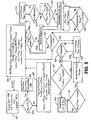
- FIG 5 is a flow chart of the logic used to determine whether a FIM motion profile is to be used, while describing several equations that may define the parameters of that motion profile, according to the present embodiment of the invention.
- FIG 5 also illustrates the control that the FIM nips depend upon if a double cut as opposed to a single cut has been performed at the cutter for sheet(s) entering the FIM module.
- L SENSOR is a constant for all cut sheet lengths, L DOC , and therefore the sensors 10 (S2) and 11 (S1) travel as an integral assembly with the adjustable FIM nips.
- the control system determines if the calculated velocity, V FIM , required to avoid a tip to tail crash at the exit of the cutter is less than or equal to calculated velocity, V RAT , required to minimize downstream transport velocities while still providing successful sheet separation at the High Speed Nip for subsequent high speed sheet accumulation.
- step 503 If step 503 is false, a changing FIM nip motion profile is required for successful material handling downstream of the Cutter if it is desired to not degrade the Cutter's cut rate performance, which is the entire objective of the invention.
- V NIPMAX is computed and the second nip should be "OFF” or disengaged by setting it in the down position.
- FIG. 8 shows this second nip in the "ON" or engaged position.
- FIG 6 shows a typical motion profile for the FIM nip, according to this embodiment of the present invention.
- the velocity (i.e. tangential speed) of the FIM nip is shown by the dark line V FIM .
- V NIPMAX is the velocity of the FIM nip when the lead edge of sheets that have just been cut are ingested into them to ensure rapid take-away from the cutter blade, thereby avoiding a tip-to-tail crash on the next web advance motion cycle of the cutter.
- the lead edge of paper reaches the FIM nip (also sometimes called a control nip).
- the lead edge reaches sensor 10 and/or 11 .
- the deceleration of the FIM nip begins.
- T 5 T CYCLE marks the end of a velocity cycle for the FIM nip, and the duration T 5 - T 0 is less than the time between paper cuts.
- the lead edge of the next sheet of paper enters the FIM nip.
- the difference T 1 - T o times the velocity V NIPMAX gives the distance L SENSOR between the center line of the FIM nip and sensors 10 and 11.
- the difference T 2 - T 1 times the velocity V NIPMAX gives the distance S DOC1 from sensor 11 light extinction (LE) to start decel.
- the distance L SENSOR plus S DOC1 is the distance (I VNIPMAX ) that the document travels with velocity V NIPMAX between T o and T 2 .
- the integral of V FIM from T 2 to T 3 is the distance (L DECEL ) that the document travels during deceleration.
- the difference T 4 - T 3 times the velocity V RAT gives the distance L RAT that the document travels with velocity V RAT .
- the sum of L VNIPMAX and L DECEL and L RAT is the distance S DOC2 from sensor 11 light extinction (LE) to start accel.
- the distance S DOC2 plus the distance L SENSOR is the document length L DOC.
- step 509 computes when the FIM nip begins to decelerate at displacement, S DOC1 , from the sensor lead edge (LE) event.
- L NIPMAX L SENSOR + S DOC1 . Since both sensors are located downstream of the FIM nip and actually travel with the FIM nips as an assembly when adjusting the location of the FIM nip for cut sheet length, L DOC , the cut sheets are always in positive control of the FIM nips when the lead edges are detected by the sensors.
- Step 509 also computes the deceleration of the FIM nips, DECEL FIM , to reduce the velocity of these nips to the velocity of the RAT module, V RAT , before the lead edge of the cut sheet(s) reach the RAT nip(s). It is critical for reliable paper handling that control nips have matched velocities while transferring cut sheets between the control nips.
- the control system determines whether or not to double cut the 2-up web at step 527.
- a double cut is executed if downstream conditions allow, thereby having the cutter cut 2 side-by-side sheets with a single guillotine blade motion.
- a first single cut cuts only one sheet that is located on the paper path side that travels the shorter inner path through the RAT module.
- a second single cut cuts the remaining sheet that travels the longer outer path through the RAT module.
- the velocity of the both the FIM nip and the urge belts are set to calculated value, V NIPMAX 529.
- V NIPMAX 529 the velocity of the both the FIM nip and the urge belts are set to calculated value, V NIPMAX 529.
- the lead edge of the inner cut sheet travels downstream and eventually reaches sensor 11 which becomes blocked at step 533.
- the control system continues to transport both cut sheets by displacement, S COC1 , where upon the deceleration of the FIM nip commences, as illustrated in FIG. 6 .
- V RAT the control system conveys the sheets at constant velocity for displacement L RAT at step 541, also shown in FIG. 6 .
- the trail edge of the sheets must exit the FIM nips.
- the FIM nips and cut sheets will accelerate back up to V NIPMAX in preparation to accept the next cut sheet(s) to be released by the cutter.
- the FIM nips must return back to original velocity, V NIPMAX , in less than one cutter cycle period, or time, T CYCLE .
- L DOC For high speed Cutter operation processing sheet length, L DOC , equal to 12 inches (30.5 cm), this period is on the order of 100 milliseconds.
- step 527 the control system determines if a double cut cannot be executed due to downstream conditions. If this is true, V NIP and V BELT are set to V NIPMAX . Using similar logic as used for the double cut, after sensor 11, becomes blocked and displacement, S COC1 . is achieved, the FIM nips decelerate to velocity, V RAT at step 521.
- the velocities at step 523 for the FIM nips and the urge belts are preserved.
- the lead edge of the outer cut sheet travels downstream and eventually reaches sensor 10, which becomes blocked at step 525.
- the control system continues to transport the cut sheet by displacement S DOC3 , where upon the control system determines if the downstream conditions will accept a double cut at 527.
- FIG. 7 illustrates a simplified method 700 according to an embodiment of the invention.
- Paper is cut 705 using a paper cutter.
- the sheet is accepted 710 into a nip, such as the FIM nip shown in FIG 4 .
- the nip is operated 715 at an initial rate to move the sheet from the cutter at an initial speed. If the sheet's length divided by its width is less than a threshold value, the nip is operated at a constant rate. However, if that ratio is greater than a threshold value, then the nip rate decreases 735, until the sheet exits the nip at which time the nip returns 740 to its initial rate.
- a downstream nip will be operated at a uniform rate 745 equal to the final rate of the upstream nip.
- the downstream nip provides 745 the sheet to a right angle turn (RAT).
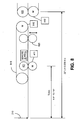
- FIG. 8 shows more details of the geometry of the FIM module 403, according to this embodiment of the invention, illustrating the geometry of the FIM nips in relation to the upstream cutter module and the downstream RAT module.
- the cutter blade 210 executes multiple cuts per second.
- the FIM nips 421 have an adjustable distance from the cutter blade (allowing for different sizes of paper).
- a motor connected to SMC 411 drives the FIM nips.
- Another motor is connected to SMC 812 for driving the urge belts 810.
- second nips 820 can be used, and these second nips 820 are preferably retractable, so that they can be retracted depending upon the size of paper sheets that are being cut.
- a further one of the motors is for SMC 413 that drives the RAT entrance nips 422.
- the fixed urge belts 810 provide non-positive drive to cut sheets which assist with the conveyance of transporting the lead edge of cut sheets reliably to the RAT entrance nips 422 during times when FIM nips 421 are primarily pushing on the trail edge of cut sheets (i.e. "pushing a rope").
- Retractable second nips 820 can be driven by the urge belts 810.
- Additional urge devices (not shown) can be used, in order to drive the paper from the cutter into the FIM nips 421.
- the second nips provide positive drive for short documents, where the distance between the FIM nips and the RAT entrance nips is greater than L DOC .
- Sensors 11 and 10 exist just downstream of the FIM nips 421, where for a 2-up web sensor 11 is the sensor on the paper path side where sheets travel an inner shorter path through the RAT module.
- Sensor 10 is the sensor on the paper path side where sheets travel a longer outer path through the RAT module.
- the embodiment described above can be implemented using a general purpose or specific-use computer system, with standard operating system software conforming to the method described herein.
- the software is designed to drive the operation of the particular hardware of the system, including the various servo motors, and will be compatible with other system components and I/O controllers.
- the computer system of this embodiment includes a CPU processor, comprising a single processing unit, multiple processing units capable of parallel operation, or the CPU can be distributed across one or more processing units in one or more locations, e.g., on a client and server.
- the computer system will advantageously also include a memory unit that includes any known type of data storage and/or transmission media, including magnetic media, optical media, random access memory (RAM), read-only memory (ROM), a data cache, a data object, etc.
- a memory unit that includes any known type of data storage and/or transmission media, including magnetic media, optical media, random access memory (RAM), read-only memory (ROM), a data cache, a data object, etc.
- the memory may reside at a single physical location, comprising one or more types of data storage, or be distributed across a plurality of physical systems in various forms.
Claims (11)
- Procédé pour accélérer et décélérer des feuilles de papier dans un système de coupe de papier, le procédé comprenant :la coupe (705) d'un film de papier à l'aide d'un dispositif de coupe (210), lorsque le papier est sensiblement arrêté, de façon à former une extrémité de queue d'une feuille de papier ;la fixation (710) d'une extrémité avant de la feuille de papier dans un pincement ;l'actionnement (715) du pincement de façon à éloigner la feuille de papier du dispositif de coupe ;la décélération (735) du pincement afin de ralentir la feuille de papier à une vitesse finale au moins au moment où l'extrémité de queue de la feuille de papier sort du pincement ; etla répétition de l'opération du pincement afin d'éloigner encore davantage les feuilles de papier du dispositif de coupe ;dans lequel la vitesse finale de chaque feuille de papier est établie à une valeur prédéterminée, celle-ci étant suffisamment basse pour satisfaire aux exigences de traitement aval (745) de la feuille de papier,
dans lequel la vitesse moyenne de chaque feuille de papier, lorsqu'elle est fixée dans le pincement, est supérieure à la vitesse finale, et
dans lequel la vitesse moyenne est suffisamment élevée pour éviter un contact entre chaque feuille de papier et le film, mais suffisamment basse pour empêcher l'extrémité avant de chaque feuille de papier de venir en contact avec une feuille aval. - Procédé selon la revendication 1, dans lequel la décélération est non nulle si et seulement si la feuille de papier a des dimensions dépassant au moins un seuil, sans quoi la feuille de papier a une vitesse sensiblement constante lorsqu'elle est déplacée par le pincement.
- Procédé selon la revendication 2, dans lequel le seuil au nombre d'au moins un est un rapport de la longueur de feuille divisée par la largeur de feuille.
- Procédé selon la revendication 3, dans lequel la vitesse finale dépend dudit rapport de la longueur de feuille divisée par la largeur de feuille.
- Procédé selon la revendication 1,
dans lequel le traitement aval (745) comprend un tournant à angle droit,
dans lequel, lorsque la feuille de papier est à la vitesse finale, le pincement a une vitesse finale correspondante égale à une vitesse sensiblement constante d'un pincement aval, et
dans lequel le pincement aval précède le tournant du tournant à angle droit. - Procédé selon la revendication 1,
dans lequel le pincement ralentit chaque feuille de papier à un nombre de mètres par seconde par seconde sensiblement constant,
dans lequel la vitesse finale est une valeur préprogrammée qui dépend au moins de la longueur et de la largeur de la feuille, et
dans lequel la vitesse moyenne est une valeur préprogrammée qui dépend au moins de la longueur de la feuille. - Appareil pour accélérer et décélérer des feuilles de papier dans un système de coupe de papier, l'appareil comprenant :un dispositif de coupe (210), configuré de façon à couper un film de papier lorsque le papier est sensiblement arrêté, de façon à former une extrémité de queue d'une feuille de papier ;un pincement (421) configuré de façon à fixer une extrémité avant de la feuille de papier ; etun moteur et un dispositif de commande de moteur configurés de façon à actionner le pincement afin d'éloigner la feuille de papier du dispositif de coupe (210), et configurés en outre de façon à décélérer le pincement (421) de façon à ralentir la feuille de papier à une vitesse finale au moins au moment où l'extrémité de queue de la feuille de papier sort du pincement, etconfigurés de plus de façon à répéter l'opération du pincement afin d'éloigner encore davantage les feuilles de papier du dispositif de coupe ;dans lequel la vitesse finale de chaque feuille de papier est suffisamment basse pour satisfaire aux exigences de traitement aval (745) de la feuille de papier,
dans lequel la vitesse moyenne de chaque feuille de papier, qui est fixée dans le pincement, est supérieure à la vitesse finale, et
dans lequel la vitesse moyenne est suffisamment élevée pour éviter un contact entre chaque feuille de papier et le film, mais suffisamment basse pour empêcher l'extrémité avant de chaque feuille de papier de venir en contact avec une feuille aval. - Appareil selon la revendication 7, dans lequel le moteur ou le dispositif de commande de moteur sont configurés de façon à faire en sorte que la décélération soit non nulle si et seulement si la feuille de papier a des dimensions dépassant au moins un seuil, sans quoi la feuille de papier a une vitesse sensiblement constante lorsqu'elle est déplacée par le pincement.
- Appareil selon la revendication 8, dans lequel le seuil au nombre d'au moins un est un rapport de la longueur de feuille divisée par la largeur de feuille.
- Appareil selon la revendication 9, dans lequel le moteur et le dispositif de commande de moteur sont configurés de façon à commander la vitesse finale en fonction dudit rapport de la longueur de feuille divisée par la largeur de feuille.
- Appareil selon la revendication 7,
dans lequel le traitement aval comprend un tournant à angle droit (405),
dans lequel le moteur et le dispositif de commande de moteur sont configurés de façon à commander le pincement de telle sorte que, lorsque la feuille de papier est à la vitesse finale, le pincement ait une vitesse finale correspondante égale à une vitesse sensiblement constante d'un pincement aval, et
dans lequel le pincement aval précède le tournant du tournant à angle droit.
Applications Claiming Priority (1)
| Application Number | Priority Date | Filing Date | Title |
|---|---|---|---|
| US11/607,489 US7752948B2 (en) | 2006-12-01 | 2006-12-01 | Method and apparatus for enhanced cutter throughput using an exit motion profile |
Publications (2)
| Publication Number | Publication Date |
|---|---|
| EP1927563A1 EP1927563A1 (fr) | 2008-06-04 |
| EP1927563B1 true EP1927563B1 (fr) | 2010-04-21 |
Family
ID=39146121
Family Applications (1)
| Application Number | Title | Priority Date | Filing Date |
|---|---|---|---|
| EP20070023126 Active EP1927563B1 (fr) | 2006-12-01 | 2007-11-29 | Procédé et appareil pour améliorer le rendement de découpe à l'aide d'un profil de mouvement de sortie |
Country Status (3)
| Country | Link |
|---|---|
| US (2) | US7752948B2 (fr) |
| EP (1) | EP1927563B1 (fr) |
| DE (1) | DE602007005969D1 (fr) |
Families Citing this family (5)
| Publication number | Priority date | Publication date | Assignee | Title |
|---|---|---|---|---|
| US20100042252A1 (en) * | 2008-08-13 | 2010-02-18 | Xerox Corporation | Disk type apparatus and corresponding methods |
| US8882099B2 (en) | 2009-08-25 | 2014-11-11 | Lasermax Roll Systems, Inc. | System and method for inline cutting and stacking of sheets for formation of books |
| EP2470336B1 (fr) * | 2009-08-25 | 2013-08-14 | Lasermax Roll Systems, Inc. | Système pour la coupe en ligne et la formation de pilles de feuilles pour la facture des livres |
| IT1397442B1 (it) * | 2009-12-30 | 2013-01-10 | Tecnau Srl | Apparecchiatura di taglio trasversale per fogli separabili da moduli continui sovrapposti |
| US9540203B2 (en) | 2013-11-13 | 2017-01-10 | Bell And Howell, Llc | Method and system for synchronizing items using position compensation |
Family Cites Families (44)
| Publication number | Priority date | Publication date | Assignee | Title |
|---|---|---|---|---|
| US1400777A (en) * | 1920-07-08 | 1921-12-20 | Spiess Georg | Paper-cutting device |
| US3025740A (en) * | 1957-10-23 | 1962-03-20 | Champlain Company Inc | Intermittent web feed mechanism providing low velocity feed prior to stoppage |
| DE1225476B (de) * | 1964-04-27 | 1966-09-22 | Winkler Richard | Verfahren zum Herstellen von Zuschnitten fuer Briefumschlaege aus einer laufenden Bahn aus Papier od. dgl. |
| BE757875A (fr) * | 1970-09-10 | 1971-04-22 | Kalle Ag | Dispositif pour la coupe de matiere a l'etat de ruban |
| US3902954A (en) * | 1971-11-12 | 1975-09-02 | Fmc Corp | Apparatus for making bottom seal thermoplastic bags |
| DE2556108C3 (de) * | 1975-12-12 | 1979-06-21 | Siemens Ag, 1000 Berlin Und 8000 Muenchen | Vorrichtung zur optimalen Anpassung einer numerisch gesteuerten Nibbelmaschine an den Bearbeitungsvorgang eines Werkstückes |
| US4184392A (en) * | 1976-12-30 | 1980-01-22 | Masson Scott Thrissell Engineering Ltd. | Web cutting machines |
| NL7711013A (nl) * | 1977-10-07 | 1979-04-10 | Buhrs Zaandam Bv | Snijinrichting. |
| US4880371A (en) * | 1984-11-13 | 1989-11-14 | Nabisco Brands, Inc. | Apparatus of machining doughy material |
| US5107734A (en) * | 1987-07-22 | 1992-04-28 | Armbruster Joseph M | Electrically powered dispenser for rolled sheet material |
| GB8729442D0 (en) * | 1987-12-17 | 1988-02-03 | Chambon Ltd | Carton blank die-cutting machine assembly |
| US5024128A (en) * | 1989-02-21 | 1991-06-18 | Campbell Jr Gaines P | Sheeter for web fed printing press |
| US5358592A (en) * | 1989-07-11 | 1994-10-25 | Nippon Flute Co., Ltd. | Bag making machine control |
| US5175691A (en) * | 1990-03-12 | 1992-12-29 | Pitney Bowes Inc. | System and method for controlling an apparatus to produce items in selected configurations |
| US5090683A (en) * | 1990-07-31 | 1992-02-25 | Xerox Corporation | Electronic sheet rotator with deskew, using single variable speed roller |
| US5308435A (en) * | 1991-10-07 | 1994-05-03 | Home Fashions, Inc. | Method and apparatus for fabricating honeycomb insulating material |
| US5415089A (en) * | 1991-12-19 | 1995-05-16 | Pitney Bowes Inc. | Mailing machine including printing drum deceleration and constant velocity control system |
| US5251554A (en) * | 1991-12-19 | 1993-10-12 | Pitney Bowes Inc. | Mailing machine including shutter bar moving means |
| US5295060A (en) * | 1991-12-19 | 1994-03-15 | Pitney Bowes Inc. | Mailing machine including sheet feeding control means |
| US5331576A (en) * | 1992-02-25 | 1994-07-19 | Pitney Bowes Inc. | Mailing machine including skewed sheet detection means |
| US5337248A (en) * | 1992-02-25 | 1994-08-09 | Pitney Bowes Inc. | Mailing machine including sheet feeding speed calibrating means |
| US5380109A (en) * | 1992-02-25 | 1995-01-10 | Pitney Bowes Inc. | Mailing machine including short sheet length detecting means |
| US5337660A (en) * | 1992-02-25 | 1994-08-16 | Pitney Bowes Inc. | Mailing machine including printing speed calibrating means |
| US5279195A (en) * | 1992-03-03 | 1994-01-18 | Heidelberg Harris, Inc. | Apparatus for continuously transporting, separating, and changing the path of webs |
| US5442983A (en) * | 1993-09-30 | 1995-08-22 | D'angelo; Joseph J. | All-electric web feeding, cutting and sheet dispensing machine |
| JP3478629B2 (ja) * | 1994-01-27 | 2003-12-15 | ハイデルベルガー ドルツクマシーネン アクチエンゲゼルシヤフト | 紙葉処理機械の給紙領域において紙葉を搬送する装置および電動モータの速度制御方法 |
| US5713256A (en) * | 1994-03-09 | 1998-02-03 | The Langston Corporation | Dual speed limits for a cut-off |
| JP3544789B2 (ja) * | 1996-07-17 | 2004-07-21 | 株式会社リコー | モータ制御装置及び画像読み取り装置の走行体駆動装置 |
| DE19748789C2 (de) * | 1997-11-05 | 2000-05-25 | Boewe Systec Ag | Vorrichtung zum Querschneiden einer Papierbahn |
| US6299730B1 (en) * | 1999-09-20 | 2001-10-09 | The Mead Corporation | Method and system for monitoring web defects along a moving paper web |
| US6364305B1 (en) * | 1999-12-28 | 2002-04-02 | Pitney Bowes Inc. | System and method for providing sheets to an inserter system |
| US6744590B2 (en) * | 2000-09-14 | 2004-06-01 | Samsung Electronics Co., Inc. | Seek trajectory adaptation in sinusoidal seek servo hard disk drives |
| US6570354B1 (en) * | 2000-10-27 | 2003-05-27 | Heidelberger Druckmaschinen Ag | System and method for increased sheet timing operation window for registration |
| US6443447B1 (en) * | 2000-12-29 | 2002-09-03 | Pitney Bowes Inc. | Method and device for moving cut sheets in a sheet accumulating system |
| US6474885B2 (en) * | 2001-04-05 | 2002-11-05 | Eastman Kodak Company | Roller system to help remove chad and trimmed media in a thermal printer |
| DE60311376T2 (de) * | 2002-09-27 | 2007-11-29 | Eastman Kodak Co. | System zum Einstellen der Ausricht- und Taktgeschwindigkeit |
| US7021184B2 (en) | 2003-05-27 | 2006-04-04 | Pitney Bowes Inc. | System and method for providing sheets to an inserter system using a rotary cutter |
| US20060191426A1 (en) * | 2003-06-03 | 2006-08-31 | Lee Timmerman | Bundled printed sheets |
| NZ552230A (en) * | 2004-07-01 | 2011-02-25 | Great Stuff Inc | Systems and methods for controlling spooling of linear material including a motor and controller |
| US8819103B2 (en) * | 2005-04-08 | 2014-08-26 | Palo Alto Research Center, Incorporated | Communication in a distributed system |
| US7512377B2 (en) * | 2005-04-20 | 2009-03-31 | Xerox Corporation | System and method for extending speed capability of sheet registration in a high speed printer |
| DE102006060289A1 (de) | 2005-12-21 | 2007-06-28 | Heidelberger Druckmaschinen Ag | Verfahren zum Fördern von Bedruckstoff |
| US7819393B2 (en) * | 2006-10-13 | 2010-10-26 | Pitney Bowes Inc. | Web cutter having a web cutter loop |
| US7914000B2 (en) * | 2007-06-06 | 2011-03-29 | Xerox Corporation | Feedback-based document handling control system |
-
2006
- 2006-12-01 US US11/607,489 patent/US7752948B2/en active Active
-
2007
- 2007-11-29 DE DE200760005969 patent/DE602007005969D1/de active Active
- 2007-11-29 EP EP20070023126 patent/EP1927563B1/fr active Active
-
2010
- 2010-06-03 US US12/792,962 patent/US9309082B2/en active Active
Also Published As
| Publication number | Publication date |
|---|---|
| US7752948B2 (en) | 2010-07-13 |
| US9309082B2 (en) | 2016-04-12 |
| DE602007005969D1 (de) | 2010-06-02 |
| US20100236365A1 (en) | 2010-09-23 |
| US20080128984A1 (en) | 2008-06-05 |
| EP1927563A1 (fr) | 2008-06-04 |
Similar Documents
| Publication | Publication Date | Title |
|---|---|---|
| EP1683651B1 (fr) | Contrôle de mouvement pour l'entrée d'un système d'insertion à grande vitesse | |
| US20060075860A1 (en) | System and method for providing sheets to an inserter system using a rotary cutter | |
| US9309082B2 (en) | Method and apparatus for enhanced cutter throughput using an exit motion profile | |
| US8540235B2 (en) | Conveying apparatus for envelopes and related methods | |
| US6792332B1 (en) | Method for dynamic acceleration in an article transporting system | |
| EP1433733A2 (fr) | Système de transport tampon flexible pour organiser des documents accumulés | |
| US4598901A (en) | Shingling and stacking of conveyed sheet material with pre-shingling control of sheet feed | |
| EP1577242B1 (fr) | Système et procédé pour fournir des feuilles à un système d'insertion utilisant un dispositif de coupe à haute vitesse et une rotation à angle droit | |
| EP1911706B1 (fr) | Dispositif de découpe ayant une boucle de découpe | |
| CA2392162C (fr) | Appareil et procede de distribution par echelonnement avec orientation a angle droit | |
| US6062556A (en) | Method and apparatus for merging sheets | |
| US20110169217A1 (en) | Method and Device for Transporting Paper Within a Paper Handling Installation from a First Conveyor to a Second Conveyor | |
| US6607190B1 (en) | Apparatus for providing gap control for a high-speed check feeder | |
| CN101778788B (zh) | 具有并行传送胶带的印刷机折页器 | |
| US8628080B2 (en) | Method and system for controlling a staging transport in a mail processing machine | |
| EP2409785B1 (fr) | Dispositif singulateur pour objets postaux doté d'une fonction anti-glisse | |
| JP6207853B2 (ja) | 紙葉類処理装置 | |
| WO2010118017A1 (fr) | Appareil de transport avec élément non obstructif et procédés associés |
Legal Events
| Date | Code | Title | Description |
|---|---|---|---|
| PUAI | Public reference made under article 153(3) epc to a published international application that has entered the european phase |
Free format text: ORIGINAL CODE: 0009012 |
|
| AK | Designated contracting states |
Kind code of ref document: A1 Designated state(s): AT BE BG CH CY CZ DE DK EE ES FI FR GB GR HU IE IS IT LI LT LU LV MC MT NL PL PT RO SE SI SK TR |
|
| AX | Request for extension of the european patent |
Extension state: AL BA HR MK RS |
|
| 17P | Request for examination filed |
Effective date: 20080806 |
|
| AKX | Designation fees paid |
Designated state(s): DE FR GB |
|
| GRAP | Despatch of communication of intention to grant a patent |
Free format text: ORIGINAL CODE: EPIDOSNIGR1 |
|
| GRAS | Grant fee paid |
Free format text: ORIGINAL CODE: EPIDOSNIGR3 |
|
| GRAA | (expected) grant |
Free format text: ORIGINAL CODE: 0009210 |
|
| AK | Designated contracting states |
Kind code of ref document: B1 Designated state(s): DE FR GB |
|
| REG | Reference to a national code |
Ref country code: GB Ref legal event code: FG4D |
|
| REF | Corresponds to: |
Ref document number: 602007005969 Country of ref document: DE Date of ref document: 20100602 Kind code of ref document: P |
|
| PLBE | No opposition filed within time limit |
Free format text: ORIGINAL CODE: 0009261 |
|
| STAA | Information on the status of an ep patent application or granted ep patent |
Free format text: STATUS: NO OPPOSITION FILED WITHIN TIME LIMIT |
|
| 26N | No opposition filed |
Effective date: 20110124 |
|
| REG | Reference to a national code |
Ref country code: FR Ref legal event code: ST Effective date: 20110801 |
|
| PG25 | Lapsed in a contracting state [announced via postgrant information from national office to epo] |
Ref country code: FR Free format text: LAPSE BECAUSE OF NON-PAYMENT OF DUE FEES Effective date: 20101130 |
|
| REG | Reference to a national code |
Ref country code: DE Ref legal event code: R082 Ref document number: 602007005969 Country of ref document: DE Representative=s name: HOFFMANN - EITLE PATENT- UND RECHTSANWAELTE PA, DE Ref country code: DE Ref legal event code: R081 Ref document number: 602007005969 Country of ref document: DE Owner name: DMT SOLUTIONS GLOBAL CORP. (N.D.GES.D. STAATES, US Free format text: FORMER OWNER: PITNEY BOWES, INC., STAMFORD, CONN., US |
|
| REG | Reference to a national code |
Ref country code: GB Ref legal event code: 732E Free format text: REGISTERED BETWEEN 20191128 AND 20191204 |
|
| PGFP | Annual fee paid to national office [announced via postgrant information from national office to epo] |
Ref country code: GB Payment date: 20231127 Year of fee payment: 17 |
|
| PGFP | Annual fee paid to national office [announced via postgrant information from national office to epo] |
Ref country code: DE Payment date: 20231129 Year of fee payment: 17 |