EP1926927B1 - Hochtemperaturfeste dichtungsanordnung, insbesondere für gasturbinen - Google Patents
Hochtemperaturfeste dichtungsanordnung, insbesondere für gasturbinen Download PDFInfo
- Publication number
- EP1926927B1 EP1926927B1 EP06806787A EP06806787A EP1926927B1 EP 1926927 B1 EP1926927 B1 EP 1926927B1 EP 06806787 A EP06806787 A EP 06806787A EP 06806787 A EP06806787 A EP 06806787A EP 1926927 B1 EP1926927 B1 EP 1926927B1
- Authority
- EP
- European Patent Office
- Prior art keywords
- sealing
- combustion chamber
- segment
- temperature
- turbine
- Prior art date
- Legal status (The legal status is an assumption and is not a legal conclusion. Google has not performed a legal analysis and makes no representation as to the accuracy of the status listed.)
- Not-in-force
Links
- 238000007789 sealing Methods 0.000 title claims abstract description 101
- 238000001816 cooling Methods 0.000 claims abstract description 16
- 239000007789 gas Substances 0.000 claims description 53
- 238000002485 combustion reaction Methods 0.000 claims description 50
- 239000002184 metal Substances 0.000 claims description 11
- 239000002826 coolant Substances 0.000 claims description 9
- 239000000567 combustion gas Substances 0.000 claims description 5
- 229910001092 metal group alloy Inorganic materials 0.000 claims description 5
- 230000035515 penetration Effects 0.000 claims 1
- 238000010276 construction Methods 0.000 description 7
- 238000012423 maintenance Methods 0.000 description 3
- 230000009467 reduction Effects 0.000 description 3
- 230000007704 transition Effects 0.000 description 3
- 230000008901 benefit Effects 0.000 description 2
- 230000000694 effects Effects 0.000 description 2
- 230000006872 improvement Effects 0.000 description 2
- 230000003993 interaction Effects 0.000 description 2
- 239000000463 material Substances 0.000 description 2
- 239000000203 mixture Substances 0.000 description 2
- 230000002411 adverse Effects 0.000 description 1
- 230000000712 assembly Effects 0.000 description 1
- 238000000429 assembly Methods 0.000 description 1
- 150000001875 compounds Chemical class 0.000 description 1
- 230000002349 favourable effect Effects 0.000 description 1
- 230000001788 irregular Effects 0.000 description 1
- 230000007480 spreading Effects 0.000 description 1
Images

Classifications
-
- F—MECHANICAL ENGINEERING; LIGHTING; HEATING; WEAPONS; BLASTING
- F01—MACHINES OR ENGINES IN GENERAL; ENGINE PLANTS IN GENERAL; STEAM ENGINES
- F01D—NON-POSITIVE DISPLACEMENT MACHINES OR ENGINES, e.g. STEAM TURBINES
- F01D9/00—Stators
- F01D9/02—Nozzles; Nozzle boxes; Stator blades; Guide conduits, e.g. individual nozzles
- F01D9/023—Transition ducts between combustor cans and first stage of the turbine in gas-turbine engines; their cooling or sealings
-
- F—MECHANICAL ENGINEERING; LIGHTING; HEATING; WEAPONS; BLASTING
- F16—ENGINEERING ELEMENTS AND UNITS; GENERAL MEASURES FOR PRODUCING AND MAINTAINING EFFECTIVE FUNCTIONING OF MACHINES OR INSTALLATIONS; THERMAL INSULATION IN GENERAL
- F16J—PISTONS; CYLINDERS; SEALINGS
- F16J15/00—Sealings
- F16J15/02—Sealings between relatively-stationary surfaces
- F16J15/06—Sealings between relatively-stationary surfaces with solid packing compressed between sealing surfaces
- F16J15/08—Sealings between relatively-stationary surfaces with solid packing compressed between sealing surfaces with exclusively metal packing
- F16J15/0887—Sealings between relatively-stationary surfaces with solid packing compressed between sealing surfaces with exclusively metal packing the sealing effect being obtained by elastic deformation of the packing
-
- F—MECHANICAL ENGINEERING; LIGHTING; HEATING; WEAPONS; BLASTING
- F05—INDEXING SCHEMES RELATING TO ENGINES OR PUMPS IN VARIOUS SUBCLASSES OF CLASSES F01-F04
- F05D—INDEXING SCHEME FOR ASPECTS RELATING TO NON-POSITIVE-DISPLACEMENT MACHINES OR ENGINES, GAS-TURBINES OR JET-PROPULSION PLANTS
- F05D2230/00—Manufacture
- F05D2230/60—Assembly methods
- F05D2230/64—Assembly methods using positioning or alignment devices for aligning or centring, e.g. pins
- F05D2230/642—Assembly methods using positioning or alignment devices for aligning or centring, e.g. pins using maintaining alignment while permitting differential dilatation
-
- F—MECHANICAL ENGINEERING; LIGHTING; HEATING; WEAPONS; BLASTING
- F05—INDEXING SCHEMES RELATING TO ENGINES OR PUMPS IN VARIOUS SUBCLASSES OF CLASSES F01-F04
- F05D—INDEXING SCHEME FOR ASPECTS RELATING TO NON-POSITIVE-DISPLACEMENT MACHINES OR ENGINES, GAS-TURBINES OR JET-PROPULSION PLANTS
- F05D2240/00—Components
- F05D2240/55—Seals
- F05D2240/57—Leaf seals
-
- F—MECHANICAL ENGINEERING; LIGHTING; HEATING; WEAPONS; BLASTING
- F05—INDEXING SCHEMES RELATING TO ENGINES OR PUMPS IN VARIOUS SUBCLASSES OF CLASSES F01-F04
- F05D—INDEXING SCHEME FOR ASPECTS RELATING TO NON-POSITIVE-DISPLACEMENT MACHINES OR ENGINES, GAS-TURBINES OR JET-PROPULSION PLANTS
- F05D2260/00—Function
- F05D2260/20—Heat transfer, e.g. cooling
- F05D2260/201—Heat transfer, e.g. cooling by impingement of a fluid
Definitions
- the invention relates to a high-temperature-resistant sealing arrangement with a sealing segment and a component termination connected to the sealing segment.
- the high-temperature resistant seal assembly should be used in a combustion chamber for gas turbines.
- the DE 10 2004 002 888 A1 has a gas turbine exhaust gasket sealing a space between a tail pipe and a combustion gas annulus. In the annulus, a hot gas stream is formed, which then flows into the turbine. The annulus shows a cross section that increases in the turbine direction (downstream). This reduces the wear of the turbine housing by repeated thermal expansion.
- the connection between the combustion chamber pipe end and annulus discloses the DE 10 2004 002 888 A1 a flange at the combustion chamber and a corresponding U-shaped groove at the annular space. To connect the combustion chamber with the annulus, the flange is inserted into the groove (plug connection). The combustor end is connected to the combustion gas annulus via a tail tube seal. In this case, the groove or groove is formed with a U-shaped cross section in an end portion of the end tube seal. The flange of the combustion chamber end is inserted into the groove or groove.
- the JP 2004301115 A also discloses a plug-in system with regard to the connection of the combustion chamber to an annular space. Again, a flange or a flange-like connection is formed at the combustion chamber pipe end.
- the annulus also has a groove. To connect the combustion chamber to the annulus, the flange is placed in the groove.
- the two components still attached to one another with a screw connection.
- WO 98/16764 a can combustor is disclosed in which a burner is connected to a transition tube. The output of the burner and the input of the transition tube overlap (see FIGS. 1 and 2A). In the overlapping connection area brush seals are attached.
- This type of construction therefore forms a maintenance-intensive vulnerability in the transition region between the combustion chamber pipe end and turbine inlet and is in need of improvement.
- the object of the invention to provide an improved seal assembly for high temperatures, in particular for the guidance of hot gas, which is characterized by a low tendency to leaks and long service life.
- the seal assembly should be usable in a combustion chamber for gas turbines.
- the invention is based on the observation that in the sheet metal construction discussed above, the wear is very high due to the relative movements exerted on the connection during operation, which leads to high deformations and frequent maintenance due to the short life of the seal segment and the connector.
- the components of the plug-in connection, the flange and the groove are tightly inserted into one another for fastening the two components and for protecting against hot gas leakage.
- the hot gas deforms the bond by spreading unevenly. For example, in a gas turbine, irregular and omnidirectional movements occur during operation, such as through the vanes. These relative movements are thus transferred to the seal segment and thus to the connectors.
- the expanded by the hot gas and now close interlocking components of the connector deform so inadmissible by the relative movement.
- the Life of the seal, and an associated sealing segment, such as an annulus significantly increased.
- a flexible sealing element which is mounted between a combustion chamber outlet section, and a sealing segment.
- the sealing segment is designed to be flexible and indeed in such a way that it compensates for relative movements and thermal expansions.
- the seal segment and the combustion chamber exit section have no rigid connection through the use of the flexible sealing element, as used in the plug-in system of the prior art.
- the undesirable deformation of the sealing element and the associated impermissible deformation of the sealing segment is effectively counteracted by the flexible connection. Due to this reduced deformation leaks are largely avoided.
- the flexible sealing element therefore fulfills the function of accommodating movements in the form of thermal expansion or relative movements, for example by the turbine, on the one hand, and the sealing function itself, on the other hand.
- the wear of the seal segment and the connection of the seal segment to the combustion chamber exit section is reduced by the flexible seal. This results in a longer life. The result is longer maintenance intervals than before.
- the flexible sealing element is mounted on a side facing away from the hot gas side both on the seal segment and on the component termination.
- a flange is provided on a side remote from the hot gas side on the component termination, with which the sealing element is attached.
- the seal segment has a wall which is interspersed with a number of channels. These channels serve to cool the seal segment with cooling medium. This is how the sealing segment gets ahead of the hot operating temperatures and additionally effectively protected against material damage.
- the number and arrangement of the cooling channels in the wall are advantageously adapted to the respective cooling task.
- the wall itself is cooled by an impingement cooling, for which an impingement cooling device is provided.
- the impingement cooling effects a lowering of the temperature of the sealing element in that part of the heat is dissipated to the cooling medium impinging on the wall under high pressure. This also provides additional protection against the high hot gas temperatures, which results in longer life.
- the combustion chamber outlet section is designed for the guidance of hot gas.
- the high temperature resistant seal assembly is particularly effective in this constellation. In a combustion chamber hot gases are formed, which are now passed on due to the high temperature resistant seal assembly with comparatively low hot gas loss.
- the flexible sealing element is arranged downstream of the combustion chamber outlet section in the flow direction of the hot combustion gas.
- the sealing element can intercept the movements of the adjacent components well in this arrangement.
- the sealing segment is designed for a connection between the combustion chamber outlet section and a turbine arranged downstream of the combustion chamber. Hot gas is preferably conducted from the combustion chamber via this connection to a turbine. The hot gas flowing through the turbine serves to generate energy.
- the sealing segment preferably forms an annular space.
- the resulting hot gas in the combustion chamber is guided to the turbine.
- the hot gases emerging from the combustion chamber exit section mix and form a substantially homogeneously mixed and thus improved hot gas flow. This results in a homogeneous and defined flow of the turbine inlet with the first row of vanes.
- the sealing element is made of metal or a metallic alloy.
- metal or metallic alloys are temperature-resistant and, on the other hand, have a spring-elastic component, making them particularly suitable for this type of application.
- the flexible sealing element is designed as an E-seal, a dog-bone - seal or brush-shaped.
- the sealing element can absorb and compensate for thermal and mechanical movements well, since in this type of seal, the spring-elastic component is very high.
- the high-temperature-resistant sealing arrangement is preferably provided in a combustion chamber.
- a combustion chamber This may be, for example, a Can, Can Annular or Annular combustion chamber, as provided in gas turbines.
- the gas turbine 1 has a compressor 2 for combustion air, a combustion chamber 4 and a turbine 6 for driving the compressor 2 and a generator or a work machine, not shown, and an annular space 24 for transferring the hot gas M from the combustion chamber 4 to the turbine 6.
- supplied air L is compressed.
- the turbine 6 and the compressor 2 are arranged on a common, also called turbine rotor turbine shaft 8, with which the generator or the working machine is connected, and which is rotatably mounted about its central axis.
- the turbine 6 has a number of rotatable blades 12 connected to the turbine shaft 8.
- the blades 12 are arranged in a ring on the turbine shaft 8 and thus form a number of blade rows.
- the rotor blades 6 serve to drive the turbine shaft 8 by momentum transfer from the hot medium flowing through the turbine 6, the working medium, for example the hot gas M.
- the guide vanes 14, serve to guide the flow of the working medium, for example the Hot gases M.
- the hot gas M produced, for example, in the combustion chamber 4 flows in the flow direction 38 from the combustion chamber 4 through an annular space 24 to the turbine 6.
- a substantially homogeneously mixed stream of the working medium for example a hot gas M
- the combustion chamber 4 has a combustion chamber outlet section 37.
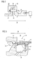
- FIG. 2 is an example of a conventional seal assembly, as used in gas turbines 1 for sealing the annular space 24 shown.
- This is a plug-in system 20, which consists of a combustion chamber outlet section 37 and a turbine inlet section 17 and an annular space 24 for transferring the resulting in the combustion chamber 4 hot gas M in the turbine 6.
- a flange 22 is formed at the combustion chamber outlet portion 37.
- the annular space 24 has a flange 22 corresponding to the U-shaped groove 26.
- the flange 22 is inserted in the groove 26.
- the flange 22 and the groove 26 is provided with a fastening bolt 28.
- a cavity 29 is provided between the flange 22 and the groove 26.
- this rigid and rigid connection prevents expansion in all directions. This causes, due to the relative movements and the thermal expansions, an increase in wear, deformation and consequently a reduction in the life of the annular space 24 and the connection of the annular space 24 to the combustion chamber exit section 37th
- a high-temperature-resistant sealing arrangement 30 according to the invention is shown.
- This has a sealing segment 31 and a component seal 32 connected to the sealing segment 31.
- the component termination 32 is connected to the seal segment 31 by a flexible sealing element 33.
- the high-temperature-resistant sealing arrangement 30 is designed for guiding hot gas M.
- the flexible sealing element 33 is preferably made of a metallic alloy or of metal. It is therefore temperature resistant. At the same time, however, it has a spring-elastic component.
- the sealing element 33 is preferably designed as an E-seal, dog-bone seal or brush-shaped. As a result, the spring-elastic component of the sealing element 33 is increased.
- the sealing element 33 absorbs the strong movements generated, for example, by a turbine 6 and compensates for them. At the same time it takes the movements by the thermal expansions of adjacent components.
- the flexible sealing element thus allows movement of all adjacent components in all directions. This causes the reduction of leakage in the connection of the sealing segment 31 with the component termination, in particular the combustion chamber outlet section.
- a flange 22 is attached to the component end 32, pointing away from the hot gas side.
- the seal segment 31 is mounted so that the component termination 32 covers a portion of the seal segment 31.
- the flexible sealing member 33 is attached to the flange and on the side of the sealing segment 31 in this cover.
- the sealing element 33 is protected from direct H preciselygasbeetzschung.
- the sealing segment 31 also has a wall 34, which is penetrated by a number of cooling channels 35. Through these cooling channels, cooling medium exits to the hot gas side and thus cools the sealing segment 31.
- the sealing segment 31 is thus protected against hot gas M.
- one or more cooling channels 35 are provided such that the outflowing cooling medium penetrates the hot gas M into a gap 45 which extends between the sealing segment 31 and the component termination 32 partially covering the sealing segment. trains, prevents.
- the flexible sealing element 33 thus receives increased cooling.
- the cooling medium is to be supplied by an impact cooling device 36.
- the cooling medium strikes the wall 34 under pressure essentially perpendicularly. As a result, a temperature exchange between the wall 34 and the cooling medium takes place.
- This efficient cooling method causes a lowering of the temperature of the sealing segment 31.
- the sealing segment 31 forms an annular space 24. In this, the hot gases mix substantially homogeneously and form a hot gas stream.
- the sealing element 33 is further downstream of the component termination 32. The components turbine 6 and seal segment 31 are in contact with each other at. Turbine movements are thus transferred to the sealing segment 31. These and the thermal expansions occurring are compensated by the flexible sealing element 33, which significantly increases the service life. Another advantage is the much easier assembly and disassembly of the sealing segment 31 against, for example, a plug-in system, due to the simpler design.
- An essential realization of the invention is the reduction of the life of a sealing segment, which is arranged in a gas turbine between a combustion chamber outlet and a turbine, essentially due to the relative movements of the turbine and the thermal expansions in connection with the occurring deformations by hot gas.
- the targeted compensation of these adverse deformations by a flexible sealing element which connects the combustion chamber outlet and the sealing segment has a favorable effect on the life of the sealing element and the sealing segment.
- the contribution of the invention for high-temperature-resistant sealing arrangements, in particular when used in a gas turbine thus has a great advantage over conventional seal assemblies and represents a significant improvement in terms of life of the commonly used connector systems.
Landscapes
- Engineering & Computer Science (AREA)
- General Engineering & Computer Science (AREA)
- Mechanical Engineering (AREA)
- Turbine Rotor Nozzle Sealing (AREA)
- Gasket Seals (AREA)
- Sealing Material Composition (AREA)
Description
- Die Erfindung betrifft eine hochtemperaturfeste Dichtungsanordnung mit einem Dichtungssegment und einem mit dem Dichtungssegment verbundenen Bauteilabschluss. Die hochtemperaturfeste Dichtungsanordnung soll in einer Brennkammer für Gasturbinen einsetzbar sein.
- Die
DE 10 2004 002 888 A1 weist eine Gasturbinen-Endrohrdichtung auf, die einen Raum zwischen einem Endrohr und einem Verbrennungsgas-Ringraum abdichtet. In dem Ringraum bildet sich ein Heißgasstrom aus, der anschließend in die Turbine strömt. Der Ringraum zeigt dabei einen Querschnitt auf, der sich in Turbinenrichtung (stromabwärts) vergrößert. Dadurch reduziert sich der Verschleiß des turbinenumhüllenden Gehäuses durch wiederholte thermische Ausdehnung. Hinsichtlich der Verbindung zwischen Brennkammer-Rohrende und Ringraum offenbart dieDE 10 2004 002 888 A1 bei dem Brennraum einen Flansch und bei dem Ringraum eine dazu korrespondierende u-förmige Nut. Zum Verbinden der Brennkammer mit dem Ringraum wird der Flansch in die Nut gesteckt (Steckverbindung). Das Brennkammerende ist mit dem Verbrennungsgas-Ringraum über eine Endrohrdichtung verbunden. Dabei ist die Rille bzw. Nut mit einem U-förmigen Querschnitt in einem Endabschnitt der Endrohrdichtung ausgebildet. Der Flansch des Brennkammerendes ist in die Rille bzw. Nut eingesetzt. - Die
JP 2004301115 A - In dem Dokument
WO 98/16764 Figuren 1 und 2A). In dem sich überlappenden Verbindungsbereich sind Bürstendichtungen angebracht.WO98/16764 - Bei den im Stand der Technik aufgezeigten Verbindungen zwischen Brennkammer und einem angrenzenden Dichtungssegment, beispielsweise eines Ringraums, zur Überführung des Heißgases zu einer Turbine handelt es sich um eine ineinander greifende Blechkonstruktionen. Diese weist eine Nut am Dichtungssegment sowie einen Flansch am Brennkammer-Rohrende auf, welche zur Befestigung direkt ineinander gesteckt sind. Das Dichtungssegment ist weiterhin endseitig auf Kontakt an der Turbine anliegend. Das Heißgas strömt so vom Brennkammer-Rohrende über das Dichtungssegment in die Turbine. Die Blechkonstruktion ist so ausgelegt, dass sie geringe Relativbewegungen der Turbine, welche in und entgegen der Strömungsrichtung des Heißgases erfolgen, aufnimmt. Die Blechkonstruktion ist mit dem Brennkammer-Endrohr starr verbunden. Die hier aufgezeigten Blechkonstruktionen und das Dichtungssegment erfahren im Betrieb jedoch starke thermische und mechanische Verformungen und damit unzulässige Leckagen und hohen Verschleiß. Dies führt zu einer geringeren Lebensdauer der Blechkonstruktion und des Dichtungssegments und demzufolge häufigen Wartungsarbeiten an der Blechkonstruktion.
- Diese Art der Konstruktion bildet daher eine wartungsintensive Schwachstelle im Übergangsbereich zwischen Brennkammer-Rohrende und Turbineneintritt und ist verbesserungswürdig.
- Daher ist es die Aufgabe der Erfindung, eine verbesserte Dichtungsanordnung für hohe Temperaturen, insbesondere für die Führung von Heißgas, anzugeben, die sich durch eine geringe Neigung zu Leckagen und langer Betriebslebensdauer auszeichnet. Die Dichtungsanordnung soll in einer Brennkammer für Gasturbinen einsetzbar sein.
- Diese Aufgabe wird erfindungsgemäß gelöst durch eine hochtemperaturfeste Dichtungsanordnung mit den Merkmalen des Anspruchs 1.
- Die Erfindung geht von der Beobachtung aus, dass bei der oben diskutierten Blechkonstruktion aufgrund der im Betrieb auf die Verbindung (Steckverbindung) ausgeübten Relativbewegungen der Verschleiß sehr hoch ist, was zu hohen Verformungen und häufiger Wartungsintensität aufgrund der geringen Lebensdauer des Dichtungssegments und der Steckverbindung führt. Die Bauteile der Steckverbindung, der Flansch und die Nut, sind zur Befestigung der beiden Bauteile und zum Schutz vor Heißgasaustritt, dicht ineinander gesteckt. Durch das Heißgas verformt sich jedoch die Verbindung, indem sie sich ungleichmäßig ausdehnt. Bei einer Gasturbine beispielsweise entstehen im Betrieb unregelmäßige und in alle Richtungen stattfindende Bewegungen, so zum Beispiel durch die Leitschaufeln. Diese Relativbewegungen übertragen sich so auf das Dichtungssegment und somit auf die Steckverbindungen. Die durch das Heißgas ausgedehnten und nun dicht ineinander greifenden Bauelemente der Steckverbindung verformen sich so durch die Relativbewegung unzulässig. Dies geschieht, indem sich die Bauteile durch die Bewegung aneinander reiben und pressen. Die Bauteile verformen sich durch die Bewegungen und den damit ausgeübten Druck auf die Bauteile sehr stark gegenseitig. Durch die Verformungen entstehen Spalte, durch die Heißgas entweicht. Die Spalte vergrößern sich, je länger die Steckverbindung in Betrieb ist. Dies erfolgt zum einen indem sich die bereits verformten Bauteile im Betriebszustand ausdehnen. Die Bauteile greifen nun nur noch bedingt ineinander, vielmehr entstehen hier bereits wieder Verformungen, welche die bereits entstandenen Spalte vergrößern. Die Folge ist ein immer größerer Heißgasverlust und eine immer geringere Dichtwirkung. Das Dichtungssegment und die Dichtung weisen wegen dieses ungünstigen Zusammenwirkens eine geringe Lebensdauer auf.
- Ausgehend von der Erkenntnis dieser Wirkzusammenhänge der Dichtkonstruktion im Stand der Technik wird nunmehr durch die erfindungsgemäße hochtemperaturfeste Dichtungsanordnung die Lebensdauer der Dichtung, und eines damit verbundenen Dichtungssegmentes, beispielsweise eines Ringraums, wesentlich erhöht. Dies erfolgt durch ein flexibles Dichtelement welches zwischen einem Brennkammer-Austrittsabschnitt, und einem Dichtungssegment angebracht ist. Das Dichtungssegment ist flexibel ausgestaltet und zwar dergestalt, dass es Relativbewegungen und thermische Dehnungen kompensiert. Das Dichtungssegment und der Brennkammer-Austrittsabschnitt weisen durch die Anwendung des flexiblen Dichtelements keine starre Verbindung auf, wie sie im Stecksystem des Stands der Technik zur Anwendung kommt. Der unerwünschten Verformung des Dichtelements und der damit verbundenen, unzulässigen Verformung des Dichtungssegments wird durch die flexible Verbindung wirksam entgegengetreten. Durch diese reduzierte Verformung sind Leckagen weitestgehend vermieden. Das flexible Dichtelement erfüllt daher einerseits die Funktion Bewegungen in Form thermischer Dehnungen oder Relativbewegungen, beispielsweise durch die Turbine, aufzunehmen und andererseits die Dichtfunktion selber. Der Verschleiß des Dichtungssegments und der Verbindung des Dichtungssegments am Brennkammer-Austrittsabschnitt ist durch die flexible Dichtung reduziert. Es ergibt sich eine längere Lebensdauer. Die Folge sind längere Wartungsintervalle als bisher.
- Bevorzugt ist das flexible Dichtelement auf einer vom Heißgas abgewandten Seite sowohl am Dichtungssegment als auch am Bauteilabschluss angebracht. Hierzu ist beispielsweise ein Flansch an einer vom Heißgas abgewandten Seite am Bauteilabschluss vorgesehen, mit dem das Dichtelement befestigt ist. Dadurch ist das Dichtelement vor unmittelbarer Beaufschlagung mit Heißgas geschützt. Die Gefahr vor Materialschäden, wie sie durch Heißgas entstehen können, ist somit reduziert.
- Das Dichtungssegment weist eine Wand auf, welche mit einer Anzahl von Kanälen durchsetzt ist. Diese Kanäle dienen dazu, das Dichtungssegment mit Kühlmedium zu kühlen. So wird das Dichtungssegment vor den heißen Einsatztemperaturen und zusätzlich vor Materialschäden wirkungsvoll geschützt. Die Anzahl und die Anordnung der Kühlkanäle in der Wand sind vorteilhafterweise an die jeweilige Kühlaufgabe angepasst.
Bevorzugt ist die Wand selber durch eine Prallkühlung gekühlt, wofür eine Prallkühleinrichtung vorgesehen ist. Durch die Prallkühlung wird eine Temperaturabsenkung des Dichtelements bewirkt, insofern, dass ein Teil der Wärme an das, auf die Wand unter hohem Druck, aufprallende Kühlmedium abgegeben wird. Dies stellt ebenfalls einen zusätzlichen Schutz vor den hohen Heißgastemperaturen dar, was eine Verlängerung der Lebensdauer bewirkt. - Der Brennkammer-Austrittsabschnitt ist für die Führung von Heißgas ausgelegt. Die hochtemperaturfeste Dichtungsanordnung ist besonders wirkungsvoll in dieser Konstellation. In einer Brennkammer werden heiße Gase gebildet, die nun aufgrund der hochtemperaturfesten Dichtungsanordnung mit vergleichsweise geringem Heißgasverlust weiter geleitet werden.
- Bevorzugt ist das flexible Dichtelement dem Brennkammer-Austrittsabschnitt in Strömungsrichtung des heißen Verbrennungsgases nachgeordnet. Das Dichtelement kann in dieser Anordnung die Bewegungen der angrenzenden Bauteile gut abfangen.
- In weiterer bevorzugter Ausgestaltung ist das Dichtungssegment für eine Verbindung zwischen Brennkammer - Austrittsabschnitt und einer der Brennkammer nachgeschalteten Turbine ausgelegt. Bevorzugt wird Heißgas so von der Brennkammer über diese Verbindung zu einer Turbine geführt. Das die Turbine durchströmende Heißgas dient zur Energieerzeugung.
- Bevorzugt bildet das Dichtungssegment einen Ringraum aus. In diesem wird das in der Brennkammer entstehende Heißgas zur Turbine geführt. In dem Ringraum vermischen sich die aus dem Brennkammer-Austrittsabschnitt austretenden heißen Gase und bilden einen im Wesentlichen homogen durchmischten und damit verbesserten Heißgasstrom. Dadurch ergibt sich eine homogene und definierte Anströmung des Turbineneintritts mit der ersten Leitschaufelreihe.
- In weiterer bevorzugter Ausgestaltung ist das Dichtelement aus Metall oder einer metallischen Legierung. Metall oder metallische Legierung sind zum einen temperaturbeständig und weisen zum anderen eine feder-elastische Komponente auf, womit sie sich besonders gut für diese Art der Anwendung eignen.
- Bevorzugt ist das flexible Dichtelement als eine E-Dichtung, eine Dog-Bone - Dichtung oder bürstenförmig ausgebildet. In dieser Ausgestaltung kann das Dichtelement thermische und mechanische Bewegungen gut aufnehmen und kompensieren, da bei dieser Art der Dichtung die feder-elastische Komponente sehr hoch ist.
- Bevorzugt ist die hochtemperaturfeste Dichtungsanordnung in einer Brennkammer vorgesehen. Dabei kann es sich beispielsweise um eine Can, Can-Annular oder Annular-Brennkammer handeln, wie sie in Gasturbinen vorgesehen sind.
- Im Folgenden wird die Erfindung beispielhaft anhand einer Zeichnung näher erläutert.
- Darin zeigt in vereinfachter und nicht maßstäblicher Darstellung:
- FIG 1
- eine schematische Darstellung einer Gasturbine,
- FIG 2
- einen Ringraum mit einer Dichtung nach dem Stand der Technik, sowie
- FIG 3
- eine hochtemperaturfeste Dichtungsanordnung gemäß der Erfindung.
- Gleiche Teile sind in allen Figuren mit denselben Bezugszeichen versehen.
- Die Gasturbine 1 gemäß
FIG 1 weist einen Verdichter 2 für Verbrennungsluft, eine Brennkammer 4 sowie eine Turbine 6 zum Antrieb des Verdichters 2 und eines nicht näher dargestellten Generators oder einer Arbeitsmaschine auf sowie einen Ringraum 24 zum Überführen des Heißgases M von der Brennkammer 4 zur Turbine 6 auf. Im Verdichter 4 wird zugeführte Luft L verdichtet. Dazu sind die Turbine 6 und der Verdichter 2 auf einer gemeinsamen, auch als Turbinenläufer bezeichneten Turbinenwelle 8 angeordnet, mit der auch der Generator bzw. die Arbeitsmaschine verbunden ist, und die um ihre Mittelachse drehbar gelagert ist. Die Turbine 6 weist eine Anzahl von mit der Turbinenwelle 8 verbundenen, rotierbaren Laufschaufeln 12 auf. Die Laufschaufeln 12 sind kranzförmig an der Turbinenwelle 8 angeordnet und bilden somit eine Anzahl von Laufschaufelreihen. Weiterhin umfasst die Turbine 6 eine Anzahl von feststehenden Leitschaufeln 14. Die Laufschaufeln 12 dienen zum Antrieb der Turbinenwelle 8 durch Impulsübertrag vom die Turbine 6 durchströmenden heißen Medium, dem Arbeitsmedium, beispielsweise des Heißgases M. Die Leitschaufeln 14 dienen hingegen zur Strömungsführung des Arbeitsmediums beispielsweise des Heißgases M. - Das in der Brennkammer 4 beispielsweise entstehende Heißgas M strömt in Strömungsrichtung 38 von der Brennkammer 4 durch einen Ringraum 24 zu der Turbine 6. In dem Ringraum 24 bildet sich ein im Wesentlichen homogen durchmischter Strom des Arbeitsmediums beispielsweise eines Heißgases M aus. Dabei weist die Brennkammer 4 einen Brennkammer-Austrittsabschnitt 37 auf. Im Betrieb der Turbine 6 und der Brennkammer 4 treten mechanische Relativbewegungen und thermische Dehnungen der Bauteile auf, die sich insbesondere im Bereich der der Verbindung zwischen Brennkammer 4 und Turbine 6 -also dem Ringraum 24- auswirken.
- In
FIG 2 ist ein Beispiel einer herkömmlichen Dichtungsanordnung, wie sie in Gasturbinen 1 zur Abdichtung des Ringraums 24 verwendet werden, dargestellt. Es handelt sich hierbei um ein Stecksystem 20, das aus einem Brennkammer-Austrittsabschnitt 37 und einem Turbine-Eintrittsabschnitt 17 besteht und einem Ringraum 24 zur Überführung des in der Brennkammer 4 entstehenden Heißgases M in die Turbine 6. Zur Befestigung des Ringraums 24 am Brennkammer-Austrittsabschnitt 37 ist am Brennkammer-Austrittsabschnitt 37 ein Flansch 22 ausgebildet. Der Ringraum 24 weist eine zum Flansch 22 korrespondierende u-förmige Nut 26 auf. Der Flansch 22 ist in die Nut 26 eingebracht. Für die Befestigung und Sicherung der Nut 26 mit dem Flansch 22 ist der Flansch 22 und die Nut 26 mit einem Befestigungsbolzen 28 versehen. Um eine gewisse thermische Ausdehnung im Betrieb zu ermöglichen, ist zwischen dem Flansch 22 und der Nut 26 ein Hohlraum 29 vorgesehen. Die Befestigung mit dem Befestigungsbolzen 28 und die Anordnung des Flansches 22 in der Nut 26 selber ermöglichen jedoch nur geringe thermische Ausdehnungen. Zusätzlich verhindert diese starre und feste Verbindung eine Ausdehnung in alle Richtungen. Dies bewirkt, aufgrund der Relativbewegungen und der thermischen Dehnungen, eine Erhöhung des Verschleiß, der Verformung und demzufolge eine Reduzierung der Lebensdauer des Ringraums 24 und der Verbindung des Ringraums 24 zum Brennkammer-Austrittsabschnitt 37. - In
FIG 3 ist dem gegenüber eine hochtemperaturfeste Dichtungsanordnung 30 gemäß der Erfindung dargestellt. Diese weist ein Dichtungssegment 31 und einem mit dem Dichtungssegment 31 verbundenen Bauteilabschluss 32 auf. Der Bauteilabschluss 32 ist durch ein flexibles Dichtelement 33 mit dem Dichtungssegment 31 verbunden. Die hochtemperaturfeste Dichtungsanordnung 30 ist dabei zum Führen von Heißgas M ausgelegt. Das flexible Dichtelement 33 ist bevorzugt aus einer metallischen Legierung oder aus Metall. Es ist damit temperaturbeständig. Gleichzeitig weist es jedoch eine feder-elastische Komponente auf. Das Dichtelement 33 ist bevorzugt als E-Dichtung, Dog-Bone-Dichtung oder bürstenförmig ausgebildet. Dadurch wird die feder-elastische Komponente des Dichtelements 33 erhöht. Das Dichtelement 33 nimmt die beispielsweise durch eine Turbine 6 erzeugten starken Bewegungen auf und kompensiert diese. Gleichzeitig nimmt es die Bewegungen durch die thermischen Dehnungen angrenzender Bauteile auf. Das flexible Dichtelement lässt somit eine Bewegung aller angrenzenden Bauteile in alle Richtungen zu. Dies bewirkt die Reduzierung der Leckagen bei der Verbindung des Dichtungssegments 31 mit dem Bauteilabschluss, insbesondere dem Brennkammer-Austrittsabschnitt.
Zum Anbringen des flexiblen Dichtelements 33 am Bauteilabschluss 32 ist am Bauteilabschluss 32 ein Flansch 22 angebracht, der von der Heißgasseite wegzeigt. Das Dichtungssegment 31 ist so angebracht, dass der Bauteilabschluss 32 einen Teil des Dichtungssegments 31 überdeckt. Das flexible Dichtelement 33 ist am Flansch und auf der Seite des Dichtungssegments 31 in dieser Überdeckung angebracht. - Somit ist das Dichtelement 33 vor direkter Heißgasbeaufschlagung geschützt. Das Dichtungssegment 31 weist weiterhin eine Wand 34 auf, welche mit einer Anzahl von Kühlkanälen 35 durchdrungen ist. Durch diese Kühlkanäle tritt Kühlmedium zur Heißgasseite aus und kühlt somit das Dichtungssegment 31. Das Dichtungssegment 31 ist so gegen Heißgas M geschützt. Zum weiteren Schutz des flexiblen Dichtelements 33 gegen Heißgas M sind eine oder mehrere Kühlkanäle 35 so vorgesehen, dass das ausströmende Kühlmedium ein Eindringen des Heißgases M in eine Spalte 45, welche sich zwischen dem Dichtungssegment 31 und dem, den das Dichtungssegment teilweise überdeckenden Bauteilabschluss 32, ausbildet, verhindert. Gleichzeitig kommt dem flexiblen Dichtelement 33 so eine verstärkte Kühlung zu. Das Kühlmedium ist durch eine Prallkühleinrichtung 36 zuzuführen. Bei der Prallkühleinrichtung 36 trifft das Kühlmedium unter Druck im Wesentlichen senkrecht auf die Wand 34 auf. Dadurch findet ein Temperaturaustausch zwischen der Wand 34 und den Kühlmedium statt. Diese effiziente Kühlmethode bewirkt eine Temperaturabsenkung des Dichtungssegments 31. Das Dichtungssegment 31 bildet einen Ringraum 24 aus. In diesem mischen sich die heißen Gase im Wesentlichen homogen und bilden einen Heißgasstrom aus. Das Dichtelement 33 ist weiterhin dem Bauteilabschluss 32 nachgeordnet. Die Bauteile Turbine 6 und Dichtungssegment 31 liegen auf Kontakt aneinander an. Turbinenbewegungen übertragen sich so auf das Dichtungssegment 31. Diese und die auftretenden thermischen Dehnungen werden vom flexiblen Dichtelement 33 kompensiert, wodurch sich die Lebensdauer deutlich erhöht.
Ein weiterer Vorteil ist die wesentlich einfachere Montage und Demontage des Dichtungssegments 31 gegenüber beispielsweise einem Stecksystem, infolge der einfacheren Konstruktion. - Eine wesentliche Erkenntnis der Erfindung ist die Verringerung der Lebensdauer eines Dichtungssegmentes, welches in einer Gasturbine zwischen einem Brennkammer-Austritt und einer Turbine angeordnet ist, im wesentlich aufgrund der Relativbewegungen der Turbine und der thermischen Dehnungen in Verbindung mit den auftretenden Verformungen durch Heißgas. Die gezielte Kompensierung dieser nachteiligen Verformungen durch ein flexibles Dichtelement, das den Brennkammer-Austritt und das Dichtungssegment verbindet, wirkt sich günstig auf die Lebensdauer des Dichtelements und des Dichtungssegments aus. Der Beitrag der Erfindung für hochtemperaturfeste Dichtungsanordnungen, insbesondere bei Anwendung in einer Gasturbine, weist somit einen großen Vorteil gegenüber üblichen Dichtungsanordnungen auf und stellt eine wesentliche Verbesserung im Hinblick auf Lebensdauer der üblicherweise benutzten Stecksysteme dar.
Claims (10)
- Hochtemperaturfeste Dichtungsanordnung (30) mit einem Bauteilabschluss (32) einer Brennkammer und einem Dichtungssegment (31), wobei das Dichtungssegment mit dem Bauteilabschluss über ein flexibles Dichtelement (33) verbunden ist und das Dichtungssegment (31) zum Führen von Heißgas (M) ausgelegt ist dadurch gekennzeichnet, dass das Dichtungssegment (31) eine Wand (34) mit einer Anzahl von Kanälen (35) aufweist, die die Wand (34) durchsetzen (3) und durch die Kühlmedium austritt,
wobei der Bauteilabschluss (32) und das Dichtungssegment (31) sich teilweise überdecken und
wobei das flexibles Dichtelement (33) vor direkter Heißgasbeaufschlagen geschützt ist indem- das Dichtelement (33) in dieser Überdeckung angebracht ist und- das ausströmende Kühlmedium ein Eindringen in diese Überdeckung verhindert. - Hochtemperaturfeste Dichtungsanordnung (30) nach Anspruch 1, dadurch gekennzeichnet, dass das flexible Dichtelement (33) auf einer vom Heißgas abgewandten Seite sowohl am Dichtungssegment (31) als auch am Bauteilabschluss (32) angebracht ist.
- Hochtemperaturfeste Dichtungsanordnung (30) nach einem der vorhergehenden Ansprüche, dadurch gekennzeichnet, dass zur Prallkühlung der Wand (34) eine Prallkühleinrichtung (36) vorgesehen ist.
- Hochtemperaturfeste Dichtungsanordnung (30) nach einem der vorhergehenden Ansprüche, dadurch gekennzeichnet, dass der Bauteilabschluss (32) ein Brennkammer - Austrittsabschnitt (37) ist, welcher zur Führung eines heißen Verbrennungsgases, insbesondere eines Heißengases (M) ausgelegt ist.
- Hochtemperaturfeste Dichtungsanordnung (30) nach Anspruch 4, dadurch gekennzeichnet, dass in Strömungsrichtung (38) des heißen Verbrennungsgases das Dichtungssegment (31) dem Brennkammer - Austrittsabschnitt (37) nachgeordnet ist.
- Hochtemperaturfeste Dichtungsanordnung (30) nach Anspruch 5, dadurch gekennzeichnet, dass das Dichtungssegment (31) für eine Verbindung zwischen Brennkammer - Austrittsabschnitt (37) und einer der Brennkammer (4) nachgeschalteten Turbine (6) ausgelegt ist.
- Hochtemperaturfeste Dichtungsanordnung (30) nach einem der vorhergehenden Ansprüche, dadurch gekennzeichnet, dass das Dichtungssegment (31) einen Ringraum (24) bildet.
- Hochtemperaturfeste Dichtungsanordnung (30) nach einem der vorhergehenden Ansprüche, dadurch gekennzeichnet, dass das Dichtelement aus Metall oder einer metallischen Legierung ist.
- Hochtemperaturfeste Dichtungsanordnung (30) nach Anspruch 8, dadurch gekennzeichnet, dass das Dichtelement eine E-Dichtung, eine Dog-Bone-Dichtung oder bürstenförmig ausgebildet ist.
- Gasturbine (1), die eine Brennkammer mit einem Bauteilabschluss und eine hochtemperaturfeste Dichtungsanordnung (30) nach einem der vorhergehenden Ansprüche aufweist.
Priority Applications (1)
| Application Number | Priority Date | Filing Date | Title |
|---|---|---|---|
| EP06806787A EP1926927B1 (de) | 2005-09-22 | 2006-09-20 | Hochtemperaturfeste dichtungsanordnung, insbesondere für gasturbinen |
Applications Claiming Priority (3)
| Application Number | Priority Date | Filing Date | Title |
|---|---|---|---|
| EP05020691A EP1767835A1 (de) | 2005-09-22 | 2005-09-22 | Hochtemperaturfeste Dichtungsanordnung, insbesondere für Gasturbinen |
| PCT/EP2006/066558 WO2007033974A1 (de) | 2005-09-22 | 2006-09-20 | Hochtemperaturfeste dichtungsanordnung, insbesondere für gasturbinen |
| EP06806787A EP1926927B1 (de) | 2005-09-22 | 2006-09-20 | Hochtemperaturfeste dichtungsanordnung, insbesondere für gasturbinen |
Publications (2)
| Publication Number | Publication Date |
|---|---|
| EP1926927A1 EP1926927A1 (de) | 2008-06-04 |
| EP1926927B1 true EP1926927B1 (de) | 2010-03-03 |
Family
ID=35695973
Family Applications (2)
| Application Number | Title | Priority Date | Filing Date |
|---|---|---|---|
| EP05020691A Withdrawn EP1767835A1 (de) | 2005-09-22 | 2005-09-22 | Hochtemperaturfeste Dichtungsanordnung, insbesondere für Gasturbinen |
| EP06806787A Not-in-force EP1926927B1 (de) | 2005-09-22 | 2006-09-20 | Hochtemperaturfeste dichtungsanordnung, insbesondere für gasturbinen |
Family Applications Before (1)
| Application Number | Title | Priority Date | Filing Date |
|---|---|---|---|
| EP05020691A Withdrawn EP1767835A1 (de) | 2005-09-22 | 2005-09-22 | Hochtemperaturfeste Dichtungsanordnung, insbesondere für Gasturbinen |
Country Status (6)
| Country | Link |
|---|---|
| US (1) | US8365538B2 (de) |
| EP (2) | EP1767835A1 (de) |
| JP (1) | JP4912407B2 (de) |
| AT (1) | ATE459832T1 (de) |
| DE (1) | DE502006006351D1 (de) |
| WO (1) | WO2007033974A1 (de) |
Families Citing this family (14)
| Publication number | Priority date | Publication date | Assignee | Title |
|---|---|---|---|---|
| EP2402659A1 (de) * | 2010-07-01 | 2012-01-04 | Siemens Aktiengesellschaft | Brennkammeraußenschale |
| US9234431B2 (en) * | 2010-07-20 | 2016-01-12 | Siemens Energy, Inc. | Seal assembly for controlling fluid flow |
| EP2428647B1 (de) * | 2010-09-08 | 2018-07-11 | Ansaldo Energia IP UK Limited | Übergangsbereich für eine Brennkammer einer Gasturbine |
| US20140091531A1 (en) * | 2012-10-03 | 2014-04-03 | General Electric Company | Spline seal with cooling pathways |
| US20170030214A1 (en) * | 2014-01-23 | 2017-02-02 | United Technologies Corporation | Conformal Air Seal With Low Friction Maxmet Layer |
| DE102014204481A1 (de) | 2014-03-11 | 2015-09-17 | Rolls-Royce Deutschland Ltd & Co Kg | Brennkammer einer Gasturbine |
| DE102014204476A1 (de) | 2014-03-11 | 2015-10-01 | Rolls-Royce Deutschland Ltd & Co Kg | Brennkammer einer Gasturbine |
| EP2952812B1 (de) * | 2014-06-05 | 2018-08-08 | General Electric Technology GmbH | Ringbrennkammer einer gasturbine und verkleidungssegment |
| US10837299B2 (en) | 2017-03-07 | 2020-11-17 | General Electric Company | System and method for transition piece seal |
| US10605297B2 (en) * | 2017-05-30 | 2020-03-31 | Sensata Technologies , Inc. | Washer fixation method and system |
| GB201800674D0 (en) * | 2018-01-16 | 2018-02-28 | Rolls Royce Plc | A combustion chamber arrangement |
| US10787923B2 (en) | 2018-08-27 | 2020-09-29 | Raytheon Technologies Corporation | Axially preloaded seal |
| US10968761B2 (en) | 2018-11-08 | 2021-04-06 | Raytheon Technologies Corporation | Seal assembly with impingement seal plate |
| CN112610984B (zh) * | 2020-12-14 | 2022-11-11 | 上海航天化工应用研究所 | 一种适用于高温高压的燃气隔离装置 |
Family Cites Families (18)
| Publication number | Priority date | Publication date | Assignee | Title |
|---|---|---|---|---|
| FR2422037A1 (fr) * | 1977-12-13 | 1979-11-02 | Alsthom Atlantique | Turbine a gaz |
| JPH0752014B2 (ja) * | 1986-03-20 | 1995-06-05 | 株式会社日立製作所 | ガスタ−ビン燃焼器 |
| US5400586A (en) * | 1992-07-28 | 1995-03-28 | General Electric Co. | Self-accommodating brush seal for gas turbine combustor |
| GB9305012D0 (en) * | 1993-03-11 | 1993-04-28 | Rolls Royce Plc | Sealing structures for gas turbine engines |
| GB2303888A (en) * | 1995-08-02 | 1997-03-05 | Rolls Royce Plc | Platform seal |
| WO1998016764A1 (en) * | 1996-10-16 | 1998-04-23 | Siemens Westinghouse Power Corporation | Brush seal for gas turbine combustor-transition interface |
| JP4031590B2 (ja) * | 1999-03-08 | 2008-01-09 | 三菱重工業株式会社 | 燃焼器の尾筒シール構造及びその構造を用いたガスタービン |
| US6419445B1 (en) * | 2000-04-11 | 2002-07-16 | General Electric Company | Apparatus for impingement cooling a side wall adjacent an undercut region of a turbine nozzle segment |
| US6450762B1 (en) * | 2001-01-31 | 2002-09-17 | General Electric Company | Integral aft seal for turbine applications |
| GB0108398D0 (en) * | 2001-04-04 | 2001-05-23 | Siemens Ag | Seal element for sealing a gap and combustion turbine having a seal element |
| JP2003035105A (ja) * | 2001-07-19 | 2003-02-07 | Mitsubishi Heavy Ind Ltd | ガスタービン分割壁 |
| JP3930274B2 (ja) * | 2001-08-27 | 2007-06-13 | 三菱重工業株式会社 | ガスタービン燃焼器 |
| JP3600912B2 (ja) | 2001-09-12 | 2004-12-15 | 川崎重工業株式会社 | 燃焼器ライナのシール構造 |
| JP3970156B2 (ja) * | 2002-10-30 | 2007-09-05 | 三菱重工業株式会社 | タービン翼環構造 |
| US6860108B2 (en) | 2003-01-22 | 2005-03-01 | Mitsubishi Heavy Industries, Ltd. | Gas turbine tail tube seal and gas turbine using the same |
| JP3795036B2 (ja) * | 2003-03-14 | 2006-07-12 | 三菱重工業株式会社 | タービン尾筒のシール構造およびシール装置 |
| JP4191552B2 (ja) * | 2003-07-14 | 2008-12-03 | 三菱重工業株式会社 | ガスタービン尾筒の冷却構造 |
| JP3958728B2 (ja) * | 2003-09-10 | 2007-08-15 | 株式会社日立製作所 | ガスタービン燃焼器構造 |
-
2005
- 2005-09-22 EP EP05020691A patent/EP1767835A1/de not_active Withdrawn
-
2006
- 2006-09-20 WO PCT/EP2006/066558 patent/WO2007033974A1/de not_active Ceased
- 2006-09-20 JP JP2008531696A patent/JP4912407B2/ja not_active Expired - Fee Related
- 2006-09-20 US US11/992,434 patent/US8365538B2/en not_active Expired - Fee Related
- 2006-09-20 EP EP06806787A patent/EP1926927B1/de not_active Not-in-force
- 2006-09-20 DE DE502006006351T patent/DE502006006351D1/de active Active
- 2006-09-20 AT AT06806787T patent/ATE459832T1/de active
Also Published As
| Publication number | Publication date |
|---|---|
| US8365538B2 (en) | 2013-02-05 |
| JP2009509087A (ja) | 2009-03-05 |
| US20100146985A1 (en) | 2010-06-17 |
| EP1926927A1 (de) | 2008-06-04 |
| DE502006006351D1 (de) | 2010-04-15 |
| ATE459832T1 (de) | 2010-03-15 |
| EP1767835A1 (de) | 2007-03-28 |
| JP4912407B2 (ja) | 2012-04-11 |
| WO2007033974A1 (de) | 2007-03-29 |
Similar Documents
| Publication | Publication Date | Title |
|---|---|---|
| DE602005004447T2 (de) | Manschettendichtung für Turbinenleitschaufeln | |
| DE69937652T2 (de) | Bürstendichtung für eine Turbomaschine | |
| EP1664489B1 (de) | Gasturbine mit einem ringförmigen dichtungsmittel | |
| EP1767835A1 (de) | Hochtemperaturfeste Dichtungsanordnung, insbesondere für Gasturbinen | |
| DE69431540T2 (de) | Abdichtung für Gasturbinen | |
| EP1389265B1 (de) | Gasturbine | |
| DE102008044445A1 (de) | Verfahren, System und Einrichtung zum Abdichten eines Turbinendiffusors | |
| EP2574731A2 (de) | Segmentiertes Bauteil | |
| DE60112222T2 (de) | Dichtungseinrichtung für die Kühldampführung in einer Gasturbine | |
| EP1736635B1 (de) | Luftführungssystem zwischen Verdichter und Turbine eines Gasturbinentriebwerks | |
| EP2084368B1 (de) | Turbinenschaufel | |
| EP2184445A1 (de) | Axial segmentierter Leitschaufelträger für einen Gasturbine | |
| CH713775A2 (de) | Turbolader. | |
| EP1672281A1 (de) | Hitzeschildelement | |
| EP1654440B1 (de) | Gasturbine mit einem dichtungselement im bereich des leitschaufelkranzes oder des laufschaufelkranzes des turbinenteils | |
| EP2347101B1 (de) | Gasturbine und zugehörige Gas- bzw. Dampfturbinenanlage | |
| EP1904717B1 (de) | HEIßGASFÜHRENDES GEHÄUSEELEMENT, WELLENSCHUTZMANTEL UND GASTURBINENANLAGE | |
| WO2009109430A1 (de) | Dichtungsanordnung und gasturbine | |
| EP1848904B1 (de) | Dichtungselement zur verwendung in einer strömungsmaschine | |
| EP2526263A2 (de) | Gehäusesystem für eine axialströmungsmaschine | |
| EP3670845B1 (de) | Strömungsmaschine mit statischer dichtungsanordnung | |
| EP2347100B1 (de) | Gasturbine mit kühleinsatz | |
| EP1731715A1 (de) | Übergangsbereich zwischen einer Brennkammer und einer Turbineneinheit | |
| EP1960636B1 (de) | Strömungsmaschine | |
| EP1422479B1 (de) | Brennkammer zur Verbrennung eines brennbaren Fluidgemisches |
Legal Events
| Date | Code | Title | Description |
|---|---|---|---|
| PUAI | Public reference made under article 153(3) epc to a published international application that has entered the european phase |
Free format text: ORIGINAL CODE: 0009012 |
|
| 17P | Request for examination filed |
Effective date: 20080218 |
|
| AK | Designated contracting states |
Kind code of ref document: A1 Designated state(s): AT BE BG CH CY CZ DE DK EE ES FI FR GB GR HU IE IS IT LI LT LU LV MC NL PL PT RO SE SI SK TR |
|
| 17Q | First examination report despatched |
Effective date: 20081203 |
|
| GRAP | Despatch of communication of intention to grant a patent |
Free format text: ORIGINAL CODE: EPIDOSNIGR1 |
|
| GRAS | Grant fee paid |
Free format text: ORIGINAL CODE: EPIDOSNIGR3 |
|
| GRAA | (expected) grant |
Free format text: ORIGINAL CODE: 0009210 |
|
| AK | Designated contracting states |
Kind code of ref document: B1 Designated state(s): AT BE BG CH CY CZ DE DK EE ES FI FR GB GR HU IE IS IT LI LT LU LV MC NL PL PT RO SE SI SK TR |
|
| REG | Reference to a national code |
Ref country code: GB Ref legal event code: FG4D Free format text: NOT ENGLISH |
|
| REG | Reference to a national code |
Ref country code: CH Ref legal event code: EP Ref country code: CH Ref legal event code: NV Representative=s name: SIEMENS SCHWEIZ AG |
|
| REG | Reference to a national code |
Ref country code: IE Ref legal event code: FG4D |
|
| REF | Corresponds to: |
Ref document number: 502006006351 Country of ref document: DE Date of ref document: 20100415 Kind code of ref document: P |
|
| REG | Reference to a national code |
Ref country code: SE Ref legal event code: TRGR |
|
| REG | Reference to a national code |
Ref country code: NL Ref legal event code: VDEP Effective date: 20100303 |
|
| PG25 | Lapsed in a contracting state [announced via postgrant information from national office to epo] |
Ref country code: LT Free format text: LAPSE BECAUSE OF FAILURE TO SUBMIT A TRANSLATION OF THE DESCRIPTION OR TO PAY THE FEE WITHIN THE PRESCRIBED TIME-LIMIT Effective date: 20100303 |
|
| LTIE | Lt: invalidation of european patent or patent extension |
Effective date: 20100303 |
|
| PG25 | Lapsed in a contracting state [announced via postgrant information from national office to epo] |
Ref country code: LV Free format text: LAPSE BECAUSE OF FAILURE TO SUBMIT A TRANSLATION OF THE DESCRIPTION OR TO PAY THE FEE WITHIN THE PRESCRIBED TIME-LIMIT Effective date: 20100303 Ref country code: PL Free format text: LAPSE BECAUSE OF FAILURE TO SUBMIT A TRANSLATION OF THE DESCRIPTION OR TO PAY THE FEE WITHIN THE PRESCRIBED TIME-LIMIT Effective date: 20100303 Ref country code: SI Free format text: LAPSE BECAUSE OF FAILURE TO SUBMIT A TRANSLATION OF THE DESCRIPTION OR TO PAY THE FEE WITHIN THE PRESCRIBED TIME-LIMIT Effective date: 20100303 Ref country code: FI Free format text: LAPSE BECAUSE OF FAILURE TO SUBMIT A TRANSLATION OF THE DESCRIPTION OR TO PAY THE FEE WITHIN THE PRESCRIBED TIME-LIMIT Effective date: 20100303 |
|
| REG | Reference to a national code |
Ref country code: IE Ref legal event code: FD4D |
|
| PG25 | Lapsed in a contracting state [announced via postgrant information from national office to epo] |
Ref country code: GR Free format text: LAPSE BECAUSE OF FAILURE TO SUBMIT A TRANSLATION OF THE DESCRIPTION OR TO PAY THE FEE WITHIN THE PRESCRIBED TIME-LIMIT Effective date: 20100604 Ref country code: CY Free format text: LAPSE BECAUSE OF FAILURE TO SUBMIT A TRANSLATION OF THE DESCRIPTION OR TO PAY THE FEE WITHIN THE PRESCRIBED TIME-LIMIT Effective date: 20100303 Ref country code: RO Free format text: LAPSE BECAUSE OF FAILURE TO SUBMIT A TRANSLATION OF THE DESCRIPTION OR TO PAY THE FEE WITHIN THE PRESCRIBED TIME-LIMIT Effective date: 20100303 Ref country code: NL Free format text: LAPSE BECAUSE OF FAILURE TO SUBMIT A TRANSLATION OF THE DESCRIPTION OR TO PAY THE FEE WITHIN THE PRESCRIBED TIME-LIMIT Effective date: 20100303 Ref country code: IE Free format text: LAPSE BECAUSE OF FAILURE TO SUBMIT A TRANSLATION OF THE DESCRIPTION OR TO PAY THE FEE WITHIN THE PRESCRIBED TIME-LIMIT Effective date: 20100303 Ref country code: ES Free format text: LAPSE BECAUSE OF FAILURE TO SUBMIT A TRANSLATION OF THE DESCRIPTION OR TO PAY THE FEE WITHIN THE PRESCRIBED TIME-LIMIT Effective date: 20100614 Ref country code: EE Free format text: LAPSE BECAUSE OF FAILURE TO SUBMIT A TRANSLATION OF THE DESCRIPTION OR TO PAY THE FEE WITHIN THE PRESCRIBED TIME-LIMIT Effective date: 20100303 |
|
| PG25 | Lapsed in a contracting state [announced via postgrant information from national office to epo] |
Ref country code: CZ Free format text: LAPSE BECAUSE OF FAILURE TO SUBMIT A TRANSLATION OF THE DESCRIPTION OR TO PAY THE FEE WITHIN THE PRESCRIBED TIME-LIMIT Effective date: 20100303 Ref country code: SK Free format text: LAPSE BECAUSE OF FAILURE TO SUBMIT A TRANSLATION OF THE DESCRIPTION OR TO PAY THE FEE WITHIN THE PRESCRIBED TIME-LIMIT Effective date: 20100303 Ref country code: IS Free format text: LAPSE BECAUSE OF FAILURE TO SUBMIT A TRANSLATION OF THE DESCRIPTION OR TO PAY THE FEE WITHIN THE PRESCRIBED TIME-LIMIT Effective date: 20100703 Ref country code: BG Free format text: LAPSE BECAUSE OF FAILURE TO SUBMIT A TRANSLATION OF THE DESCRIPTION OR TO PAY THE FEE WITHIN THE PRESCRIBED TIME-LIMIT Effective date: 20100603 |
|
| PLBE | No opposition filed within time limit |
Free format text: ORIGINAL CODE: 0009261 |
|
| STAA | Information on the status of an ep patent application or granted ep patent |
Free format text: STATUS: NO OPPOSITION FILED WITHIN TIME LIMIT |
|
| PG25 | Lapsed in a contracting state [announced via postgrant information from national office to epo] |
Ref country code: PT Free format text: LAPSE BECAUSE OF FAILURE TO SUBMIT A TRANSLATION OF THE DESCRIPTION OR TO PAY THE FEE WITHIN THE PRESCRIBED TIME-LIMIT Effective date: 20100705 Ref country code: DK Free format text: LAPSE BECAUSE OF FAILURE TO SUBMIT A TRANSLATION OF THE DESCRIPTION OR TO PAY THE FEE WITHIN THE PRESCRIBED TIME-LIMIT Effective date: 20100303 |
|
| 26N | No opposition filed |
Effective date: 20101206 |
|
| BERE | Be: lapsed |
Owner name: SIEMENS A.G. Effective date: 20100930 |
|
| PG25 | Lapsed in a contracting state [announced via postgrant information from national office to epo] |
Ref country code: MC Free format text: LAPSE BECAUSE OF NON-PAYMENT OF DUE FEES Effective date: 20100930 |
|
| PG25 | Lapsed in a contracting state [announced via postgrant information from national office to epo] |
Ref country code: BE Free format text: LAPSE BECAUSE OF NON-PAYMENT OF DUE FEES Effective date: 20100930 |
|
| PG25 | Lapsed in a contracting state [announced via postgrant information from national office to epo] |
Ref country code: LU Free format text: LAPSE BECAUSE OF NON-PAYMENT OF DUE FEES Effective date: 20100920 Ref country code: HU Free format text: LAPSE BECAUSE OF FAILURE TO SUBMIT A TRANSLATION OF THE DESCRIPTION OR TO PAY THE FEE WITHIN THE PRESCRIBED TIME-LIMIT Effective date: 20100904 |
|
| PG25 | Lapsed in a contracting state [announced via postgrant information from national office to epo] |
Ref country code: TR Free format text: LAPSE BECAUSE OF FAILURE TO SUBMIT A TRANSLATION OF THE DESCRIPTION OR TO PAY THE FEE WITHIN THE PRESCRIBED TIME-LIMIT Effective date: 20100303 |
|
| REG | Reference to a national code |
Ref country code: AT Ref legal event code: MM01 Ref document number: 459832 Country of ref document: AT Kind code of ref document: T Effective date: 20110920 |
|
| PG25 | Lapsed in a contracting state [announced via postgrant information from national office to epo] |
Ref country code: AT Free format text: LAPSE BECAUSE OF NON-PAYMENT OF DUE FEES Effective date: 20110920 |
|
| REG | Reference to a national code |
Ref country code: FR Ref legal event code: PLFP Year of fee payment: 10 |
|
| PGFP | Annual fee paid to national office [announced via postgrant information from national office to epo] |
Ref country code: GB Payment date: 20150909 Year of fee payment: 10 |
|
| PGFP | Annual fee paid to national office [announced via postgrant information from national office to epo] |
Ref country code: FR Payment date: 20150910 Year of fee payment: 10 Ref country code: SE Payment date: 20150907 Year of fee payment: 10 |
|
| PGFP | Annual fee paid to national office [announced via postgrant information from national office to epo] |
Ref country code: IT Payment date: 20150924 Year of fee payment: 10 |
|
| PGFP | Annual fee paid to national office [announced via postgrant information from national office to epo] |
Ref country code: DE Payment date: 20151120 Year of fee payment: 10 Ref country code: CH Payment date: 20151202 Year of fee payment: 10 |
|
| REG | Reference to a national code |
Ref country code: DE Ref legal event code: R119 Ref document number: 502006006351 Country of ref document: DE |
|
| PG25 | Lapsed in a contracting state [announced via postgrant information from national office to epo] |
Ref country code: SE Free format text: LAPSE BECAUSE OF NON-PAYMENT OF DUE FEES Effective date: 20160921 |
|
| REG | Reference to a national code |
Ref country code: CH Ref legal event code: PL |
|
| REG | Reference to a national code |
Ref country code: SE Ref legal event code: EUG |
|
| GBPC | Gb: european patent ceased through non-payment of renewal fee |
Effective date: 20160920 |
|
| REG | Reference to a national code |
Ref country code: FR Ref legal event code: ST Effective date: 20170531 |
|
| PG25 | Lapsed in a contracting state [announced via postgrant information from national office to epo] |
Ref country code: LI Free format text: LAPSE BECAUSE OF NON-PAYMENT OF DUE FEES Effective date: 20160930 Ref country code: GB Free format text: LAPSE BECAUSE OF NON-PAYMENT OF DUE FEES Effective date: 20160920 Ref country code: CH Free format text: LAPSE BECAUSE OF NON-PAYMENT OF DUE FEES Effective date: 20160930 Ref country code: DE Free format text: LAPSE BECAUSE OF NON-PAYMENT OF DUE FEES Effective date: 20170401 Ref country code: FR Free format text: LAPSE BECAUSE OF NON-PAYMENT OF DUE FEES Effective date: 20160930 |
|
| PG25 | Lapsed in a contracting state [announced via postgrant information from national office to epo] |
Ref country code: IT Free format text: LAPSE BECAUSE OF NON-PAYMENT OF DUE FEES Effective date: 20160920 |