EP1925902A1 - Zielvorrichtung mit integriertem Abstandsanzeiger - Google Patents
Zielvorrichtung mit integriertem Abstandsanzeiger Download PDFInfo
- Publication number
- EP1925902A1 EP1925902A1 EP07291366A EP07291366A EP1925902A1 EP 1925902 A1 EP1925902 A1 EP 1925902A1 EP 07291366 A EP07291366 A EP 07291366A EP 07291366 A EP07291366 A EP 07291366A EP 1925902 A1 EP1925902 A1 EP 1925902A1
- Authority
- EP
- European Patent Office
- Prior art keywords
- images
- missile
- detector
- infrared detector
- flashes
- Prior art date
- Legal status (The legal status is an assumption and is not a legal conclusion. Google has not performed a legal analysis and makes no representation as to the accuracy of the status listed.)
- Granted
Links
Images


Classifications
-
- G—PHYSICS
- G01—MEASURING; TESTING
- G01S—RADIO DIRECTION-FINDING; RADIO NAVIGATION; DETERMINING DISTANCE OR VELOCITY BY USE OF RADIO WAVES; LOCATING OR PRESENCE-DETECTING BY USE OF THE REFLECTION OR RERADIATION OF RADIO WAVES; ANALOGOUS ARRANGEMENTS USING OTHER WAVES
- G01S3/00—Direction-finders for determining the direction from which infrasonic, sonic, ultrasonic or electromagnetic waves, or particle emission, not having a directional significance, are being received
- G01S3/78—Direction-finders for determining the direction from which infrasonic, sonic, ultrasonic or electromagnetic waves, or particle emission, not having a directional significance, are being received using electromagnetic waves other than radio waves
- G01S3/782—Systems for determining direction or deviation from predetermined direction
- G01S3/783—Systems for determining direction or deviation from predetermined direction using amplitude comparison of signals derived from static detectors or detector systems
- G01S3/784—Systems for determining direction or deviation from predetermined direction using amplitude comparison of signals derived from static detectors or detector systems using a mosaic of detectors
-
- F—MECHANICAL ENGINEERING; LIGHTING; HEATING; WEAPONS; BLASTING
- F41—WEAPONS
- F41G—WEAPON SIGHTS; AIMING
- F41G7/00—Direction control systems for self-propelled missiles
- F41G7/20—Direction control systems for self-propelled missiles based on continuous observation of target position
- F41G7/30—Command link guidance systems
- F41G7/301—Details
- F41G7/303—Sighting or tracking devices especially provided for simultaneous observation of the target and of the missile
-
- F—MECHANICAL ENGINEERING; LIGHTING; HEATING; WEAPONS; BLASTING
- F41—WEAPONS
- F41G—WEAPON SIGHTS; AIMING
- F41G7/00—Direction control systems for self-propelled missiles
- F41G7/20—Direction control systems for self-propelled missiles based on continuous observation of target position
- F41G7/30—Command link guidance systems
- F41G7/301—Details
- F41G7/308—Details for guiding a plurality of missiles
Definitions
- the present invention relates to an integrated devometer sighting system.
- a system is particularly suitable for locating missiles in flight for guidance on a target, such as an armored vehicle or a bunker.
- the position in said matrix of the photosensitive element (s) excited by said successive flashes is representative of the position of said missile relative to the axis of said optical system.
- differential gauge When such a differential gauge is used in an alignment guided missile firing station, it is associated with a day sighting device (telescope) and / or a night vision device (thermal camera) at the same time. use of the operator of said firing station.
- a day sighting device Telescope
- a night vision device thermo camera
- the day-sighting device forms a direct optical channel capable of transmitting laser aggression to the operator.
- the missile is slaved to the line of sight of the day-sighting device or that of the night-sighting device, the missile guidance is very sensitive to movements. inopportune or poorly controlled that the operator prints to said system (for example during the unloading of the missile out of its launching tube, during the tracking of a high-scrolling target, annoying during the aiming, etc ). This results in a disturbed guidance for the missile, which possibly can even out of the field of said system.
- the subject of the present invention is an integrated devometer sighting system making it possible to remedy the aforementioned drawbacks.
- the images in the medium infrared are thermal images of the observed scene, suitable for daytime aiming and night aiming.
- the day sighting device and the night sighting device are therefore no longer necessary.
- the system according to the invention therefore has only one channel for the localization, sighting and night aiming functions, so that its optical, electronic and mechanical components are clearly simplified, more compact and lighter, which makes it possible to obtain an easily portable shooting range by an infantryman and much less expensive than the current firing points.
- Harmonization of the day / night channels and the localization channel is perfect, since there is only one optical axis, which eliminates any residual defects and thus avoids a complex opto-mechanical architecture to guarantee harmonization performance, especially in temperature, or a temperature correction device, as was necessary in previous solutions. Removing any misalignment (bias) between sighting and guidance improves the guidance accuracy of the system.
- the system according to the invention may comprise only one field of view (of the order of 6 ° to 8 °), serving both to support the missile during its launch and guiding said missile towards the target.
- the matrix of said infrared detector is composed of photosensitive elements of indium antimonide or telluride of mercury and cadmium.
- the time separating a shot in an interval between two successive flashes of light and a synchronous shooting with one of these is at most equal to 15 milliseconds.
- these two shots can be considered simultaneous.
- said infrared detector forms the images by integration and consecutive reading and the integration time of the images corresponding to shots in synchronism with said light flashes is chosen at most equal to 200 microseconds, while the time of integration of images corresponding to shots in the intervals between said successive flashes is advantageously between 1 and 5 milliseconds.
- said infrared detector operates in IWR mode (Integrate While Read) so that, during the reading of each image corresponding to a shooting in synchronism with a luminous flash, said electronic control means can trigger an additional shooting said scene giving rise to an additional image at least approximately identical (except for the image of said luminous flash) to said image corresponding to a shooting in synchronism with a luminous flash.
- an image processor adapted to compare the latter image and said additional image to unambiguously deduce the position of the image of said missile on said detector.
- the difference between these two images makes it possible to keep, in the image of difference, only the information concerning the luminous flash (that is to say the missile) while eliminating the sources of jamming and false emissions (solar effects for example).
- the quasi-simultaneous acquisition, on said infrared detector, of the images of said chips and of the target which allows the differential automatic tracking of the missile on the target, thus avoiding the disadvantages due to movements of the operator, especially for missiles fired at the shoulder.
- the system according to the present invention then comprises a calculator calculating the differential deviation measurement between said missile and said target on the basis of information delivered by said infrared detector and relative to the respective positions, on said matrix, of images corresponding to shots in synchronism with said successive flashes of light and images corresponding to shots in the intervals between said luminous flashes.
- Said means capable of synchronizing the taking of images of said infrared detector with said successive flashes of light may be temporary or permanent.
- said light flashes can be triggered from said missile or from said infrared detector.
- said electronic control means of the infrared detector may be able to control the optical emitters of at least two missiles so that said optical emitters generate nested sequences of light flashes.
- the figure 1 shows the block diagram of a sighting system according to the present invention.
- the figure 2 is a block diagram illustrating an exemplary embodiment of the electronic control unit and treatment of the infrared detector and the optical transmitter of the missile.
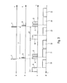
- the figure 3 shows, as a function of time t, four timing diagrams illustrating a mode of operation of the sighting system according to the invention.
- the figure 4 also shows four timing diagrams illustrating a variant of operation of the sighting system according to the invention.
- the day / night sighting system with integrated devometer 1, according to the present invention and shown in FIG. figure 1 is intended for the guidance in alignment of a missile 2 on a target 3. It comprises a single axis LL, at least approximately pointed at said target 3.
- the missile 2 is equipped with an optical transmitter 4 generating flashlights 5 in the near infrared.
- Said optical transmitter 4 may be a flash tag (xenon lamp, laser diode, ...) or a simple element reflecting light flashes from a fixed beacon to the system 1.
- the aiming system 1 comprises a single optical system of axis LL and, in the focal plane thereof, a planar infrared detector 7, at least approximately orthogonal to said axis LL of the system 1.
- a double bandpass filter 8 is disposed between the optical system 6 and the infrared detector 7.
- the infrared detector 7 comprises, for example, a matrix of photosensitive elements of indium antimonide or telluride of mercury and cadmium, disposed in a dewar connected to a cooling device not shown.
- the filter 8 can also be of the cooled type and it can be housed in the cooler of the detector 7.
- the infrared detector 7 comprises a high number of photosensitive elements, for example 640 ⁇ 512 or 1280 ⁇ 1024, and it can operate in "snapshot" mode, that is to say that all the photosensitive elements integrate at the same time the portion of the scene that 'they are watching.
- the detector 7 has a field of the order of 6 ° to 8 ° and an angular resolution at least as good as 0.3 mrad, preferably 0.1 mrad.
- the infrared detector 7 is able to operate in IWR mode, that is to say it can integrate an image while the previous image is read.
- the infrared detector 7 is sensitive both in the infrared medium corresponding to the spectral window of 3 to 5 ⁇ m in order to be able to form thermal images and in the near infrared emitted by the luminous chips 5.
- the spectral selectivity is ensured by the 8.
- the bandwidth of the filter 8 is precisely adapted to the emission spectral band of the light flashes 5, which allows to largely eliminate the radiation of the observed scene and thus to guarantee a high signal-to-noise ratio, during the image-taking of the flashes 5.
- the bandwidth of the filter 8 is precisely adapted to the spectral response of the detector 7, to allow thermal targeting with a good level of sensitivity.
- the aiming system 1 comprises an electronic command and processing unit 9 which makes it possible, in particular, to take images 3 'of the target 3 and images 5' (representative of the missile 2) of the fragments 5 emitted by the transmitter 4 by the infrared detector 7.
- a synchronization symbolized by the dashed line 10 in the figures) between the electronic block 9 and the transmitter 4 allows the taking of the images 5 'during the short duration of the flashlights 5 (from a few microseconds to a few dozens of microseconds).
- a display block 11 for example of the monitor type, is incorporated in the sighting system 1 and is capable of supplying an operator 1 2 with the thermal image in the mid-infrared of the scene in which the target 3 is located.
- the optical transmitter 4 comprises a source 13 (xenon lamp, laser diode, ...) generating the chips 5 and controlled by a triggering electronics 14, itself controlled by a sequencer 15 driven by a time base 16 .
- the electronic control and processing unit 9 comprises a device 9A for controlling the matrix detector 7 and a device 9B for image processing and deviation measurement.
- the device 9A includes a time base 17, connected to an image acquisition processor 18, which controls the sequencer 19 of the detector 7.
- the sequencer 19 controls the electronic implementation 20 of the latter.
- An interface electronics 21 allows the synchronization of images of the detector 7 with the light bursts 5, thanks to the link 10 existing between the transmitter 4 and the block 9.
- the synchronization link 10 can be established before firing the missile 2 and be maintained during the flight thereof by the stability of the time bases 16 and 17. It can also be established by microwave link or by a cable that runs as the advance of the missile 2 .
- the device 9B includes an image memory 22, connected to the detector 7, and an image processing processor 23 in connection with the memory 22 and controlling a calculator 24 for differential deviation between the missile 2 and the target 3.
- the calculator 24 controls a calculator 25 for guiding the missile 2.
- the device 9A opens an integration window i1 of a few tens of ⁇ s, allowing the detector 7 to integrate the scene that it observes through the optical system 6 and which includes the corresponding brightness 5 (see chronogram c).
- the device 9A opens another integration window i2, preferably identical to the integration window i1 but temporally very little offset from the corresponding top ⁇ .
- the image I2 corresponding to an integration window i2 thus represents the same scene as the associated image I1, but without the 5 'image of the brightness 5.
- the difference image I1-I2 formed in FIG. the device 9B includes only the image of the chip 5 and completely eliminates the scene in which are the target 3 and the missile 2, including any jammers that may be there.
- the device 9A opens long integration windows i3, for example of a duration of 0.5 ms to 5 ms, for forming images I3 of the scene comprising the target 3 and able to form the thermal images displayed on the display block 11.
- the images 5 'and 3' respectively representative of the missile 2 and of the target 3 are formed at very close times.
- the distance separating said images from said detector 7 is therefore known, which allows the computer 24 to perform the differential deviation between the missile 2 and the target 3 and to control accordingly the guidance computer 25. It is possible to overcome guiding errors from inadvertent movements applied to the sighting system 1 , both by the operator and by the firing of the missile 2. Moreover, thanks to such differential deviation, the operator can, before firing the missile 2, select precisely within the target 3 a point of desired impact, on which the missile will be guided.
- the missiles 2A and 2B can thus be guided towards the same target or on two different targets, by differential deviation measurements from the positions of the images of said missiles and said targets on said infrared detector 7.
Landscapes
- Engineering & Computer Science (AREA)
- Combustion & Propulsion (AREA)
- General Engineering & Computer Science (AREA)
- Physics & Mathematics (AREA)
- Chemical & Material Sciences (AREA)
- Electromagnetism (AREA)
- General Physics & Mathematics (AREA)
- Radar, Positioning & Navigation (AREA)
- Remote Sensing (AREA)
- Aiming, Guidance, Guns With A Light Source, Armor, Camouflage, And Targets (AREA)
- Closed-Circuit Television Systems (AREA)
- Optical Radar Systems And Details Thereof (AREA)
- Road Signs Or Road Markings (AREA)
- Iron Core Of Rotating Electric Machines (AREA)
- Paper (AREA)
- Position Fixing By Use Of Radio Waves (AREA)
- Diaphragms For Electromechanical Transducers (AREA)
- Organic Low-Molecular-Weight Compounds And Preparation Thereof (AREA)
- Transition And Organic Metals Composition Catalysts For Addition Polymerization (AREA)
- Led Device Packages (AREA)
- Photometry And Measurement Of Optical Pulse Characteristics (AREA)
Applications Claiming Priority (1)
| Application Number | Priority Date | Filing Date | Title |
|---|---|---|---|
| FR0610165A FR2908874B1 (fr) | 2006-11-21 | 2006-11-21 | Systeme de visee a ecartometre integre. |
Publications (2)
| Publication Number | Publication Date |
|---|---|
| EP1925902A1 true EP1925902A1 (de) | 2008-05-28 |
| EP1925902B1 EP1925902B1 (de) | 2009-05-13 |
Family
ID=38169313
Family Applications (1)
| Application Number | Title | Priority Date | Filing Date |
|---|---|---|---|
| EP07291366A Not-in-force EP1925902B1 (de) | 2006-11-21 | 2007-11-15 | Zielvorrichtung mit integriertem Abweichungsanzeiger |
Country Status (8)
| Country | Link |
|---|---|
| US (1) | US8022343B2 (de) |
| EP (1) | EP1925902B1 (de) |
| AT (1) | ATE431537T1 (de) |
| DE (1) | DE602007001124D1 (de) |
| ES (1) | ES2324687T3 (de) |
| FR (1) | FR2908874B1 (de) |
| IL (1) | IL198280A (de) |
| WO (1) | WO2008062114A1 (de) |
Cited By (3)
| Publication number | Priority date | Publication date | Assignee | Title |
|---|---|---|---|---|
| FR2954586A1 (fr) * | 2009-12-23 | 2011-06-24 | Thales Sa | Dispositif de detection de tache a ecartometre matriciel. |
| EP2515066A1 (de) | 2011-04-21 | 2012-10-24 | Thales | Vorrichtung zur differenziellen Führung mit Hilfe von aktiver Laserbildgebung |
| RU2490581C2 (ru) * | 2011-11-22 | 2013-08-20 | Михаил Витальевич Головань | Автоматизированная система визирования оператора |
Families Citing this family (11)
| Publication number | Priority date | Publication date | Assignee | Title |
|---|---|---|---|---|
| CA2729172A1 (en) * | 2008-06-26 | 2010-04-22 | Flir Systems, Inc. | Emitter tracking system |
| US8274425B2 (en) * | 2010-12-29 | 2012-09-25 | Raytheon Company | Single channel semi-active radar seeker |
| FI124434B (en) * | 2012-10-31 | 2014-08-29 | Metso Automation Oy | Method and apparatus for track monitoring |
| EP2920773A4 (de) | 2012-11-16 | 2016-07-06 | Flir Systems | Synchronisierte infrarotbake/infrarotdetektionssystem |
| US9555899B2 (en) * | 2014-03-27 | 2017-01-31 | The United States Of America As Represented By The Secretary Of The Navy | Mobile arresting system |
| DE102015010276A1 (de) * | 2014-12-19 | 2016-06-23 | Mbda Deutschland Gmbh | Verfahren und Vorrichtung zur lokalen Stabilisierung eines Strahlungsflecks auf einem entfernten Zielobjekt |
| EP3640677B1 (de) * | 2018-10-17 | 2023-08-02 | Trimble Jena GmbH | Verfolger einer vermessungsvorrichtung zur verfolgung eines ziels |
| EP3640590B1 (de) | 2018-10-17 | 2021-12-01 | Trimble Jena GmbH | Vermessungsvorrichtung zur vermessung eines objekts |
| US10972648B2 (en) * | 2018-12-31 | 2021-04-06 | Flir Surveillance, Inc. | Pulse detection and synchronized pulse imaging systems and methods |
| EP4553538A3 (de) | 2019-02-15 | 2025-08-13 | Trimble Inc. | Vermessungsinstrument und verfahren zur kalibrierung eines vermessungsinstruments |
| US12480763B2 (en) | 2020-10-02 | 2025-11-25 | Teledyne Flir Defense, Inc. | Lightweight laser designator systems and methods |
Citations (5)
| Publication number | Priority date | Publication date | Assignee | Title |
|---|---|---|---|---|
| EP0206912A1 (de) | 1985-06-17 | 1986-12-30 | AEROSPATIALE Société Nationale Industrielle | System zur Bestimmung der Position eines bewegten Ziels |
| EP0425355A1 (de) * | 1989-10-23 | 1991-05-02 | AEROSPATIALE Société Nationale Industrielle | Ortungssystem für einen beweglichen Körper |
| EP0633457A1 (de) * | 1993-07-05 | 1995-01-11 | AEROSPATIALE Société Nationale Industrielle | Fotoelement und Vorrichtung zur Detektion von Lichtpulsen |
| EP0740123A1 (de) * | 1995-04-24 | 1996-10-30 | Aerospatiale Societe Nationale Industrielle | System zur Bestimmung der Lage und des Rollwinkels eines sich bewegenden Objektes |
| US20020154293A1 (en) * | 2001-04-19 | 2002-10-24 | Wells Michael L. | Solid state modulated beacon tracking system |
Family Cites Families (21)
| Publication number | Priority date | Publication date | Assignee | Title |
|---|---|---|---|---|
| US4040744A (en) * | 1973-10-05 | 1977-08-09 | General Dynamics | Multiple spectrum co-axial optical sight and closed loop gun control system |
| US4419012A (en) * | 1979-09-11 | 1983-12-06 | Elliott Brothers (London) Limited | Position measuring system |
| US4424943A (en) * | 1981-05-04 | 1984-01-10 | Hughes Aircraft Company | Tracking system |
| SE455539B (sv) * | 1986-05-23 | 1988-07-18 | Electrolux Ab | Elektrooptiskt positionskennande system for ett i plan rorligt foremal, foretredesvis en mobil robot |
| FR2602057B1 (fr) * | 1986-07-22 | 1988-11-04 | Matra | Procede et dispositif de mesure de distance par voie optique |
| DE3701296C1 (de) * | 1987-01-17 | 1988-05-11 | Messerschmitt Boelkow Blohm | Anordnung zum Bestimmen der Position eines Laserstrahles in einem streuenden Medium |
| GB2282722B (en) * | 1987-07-30 | 1995-08-09 | Buck Chem Tech Werke | Infra-red search head for the location of enemy helicopters |
| NO164946C (no) * | 1988-04-12 | 1990-11-28 | Metronor As | Opto-elektronisk system for punktvis oppmaaling av en flates geometri. |
| US4932777A (en) * | 1988-09-30 | 1990-06-12 | The United States Of America As Represented By The Administrator Of The National Aeronautics And Space Administration | Electro-optical spin measurement system |
| US5023845A (en) * | 1988-10-31 | 1991-06-11 | The United States Of America As Represented By The Secretary Of The Navy | Embedded fiber optic beam displacement sensor |
| FR2643723B1 (fr) * | 1989-02-24 | 1991-07-26 | Sodern | Dispositif de determination de la direction du centre energetique d'un objet lumineux |
| US5085507A (en) * | 1989-12-27 | 1992-02-04 | Texas Instruments Incorporated | Device for three dimensional tracking of an object |
| FR2672988A1 (fr) * | 1991-02-15 | 1992-08-21 | Sodern | Procede de mesure de la position precise du centre energetique d'une tache image d'un objet lumineux sur un detecteur photosensible. |
| FR2672989A1 (fr) * | 1991-02-15 | 1992-08-21 | Sodern | Dispositif de determination de la direction d'une source emissive de faible luminosite et son application a la visee stellaire. |
| JPH07234105A (ja) * | 1994-02-23 | 1995-09-05 | Wacom Co Ltd | 光点位置計測方法 |
| FR2736146B1 (fr) * | 1995-06-28 | 1997-08-22 | Aerospatiale | Systeme de guidage en alignement d'un missile sur une cible |
| FR2753785B1 (fr) * | 1996-09-25 | 1998-11-13 | Autodirecteur d'un corps volant | |
| FR2848362B1 (fr) * | 2002-12-10 | 2006-04-07 | Mbda France | Procede et dispositif pour la realisation d'une liaison optique par impulsions laser |
| FR2857088B1 (fr) * | 2003-07-04 | 2005-09-16 | Mbda France | Missile tournant emettant des impulsions lumineuses. |
| FR2874434B1 (fr) * | 2004-08-20 | 2006-11-17 | Mbda France Sa | Procede et dispositif pour la realisation d'une liaison optique par eclats lumineux |
| IL173221A0 (en) * | 2006-01-18 | 2007-07-04 | Rafael Advanced Defense Sys | Devics |
-
2006
- 2006-11-21 FR FR0610165A patent/FR2908874B1/fr not_active Expired - Fee Related
-
2007
- 2007-11-15 DE DE602007001124T patent/DE602007001124D1/de not_active Expired - Fee Related
- 2007-11-15 ES ES07291366T patent/ES2324687T3/es active Active
- 2007-11-15 US US12/513,489 patent/US8022343B2/en not_active Expired - Fee Related
- 2007-11-15 EP EP07291366A patent/EP1925902B1/de not_active Not-in-force
- 2007-11-15 WO PCT/FR2007/001876 patent/WO2008062114A1/fr not_active Ceased
- 2007-11-15 AT AT07291366T patent/ATE431537T1/de not_active IP Right Cessation
-
2009
- 2009-04-21 IL IL198280A patent/IL198280A/en active IP Right Grant
Patent Citations (6)
| Publication number | Priority date | Publication date | Assignee | Title |
|---|---|---|---|---|
| EP0206912A1 (de) | 1985-06-17 | 1986-12-30 | AEROSPATIALE Société Nationale Industrielle | System zur Bestimmung der Position eines bewegten Ziels |
| US4710028A (en) | 1985-06-17 | 1987-12-01 | Aerospatiale Societe Nationale Industrielle | System for locating a body in motion |
| EP0425355A1 (de) * | 1989-10-23 | 1991-05-02 | AEROSPATIALE Société Nationale Industrielle | Ortungssystem für einen beweglichen Körper |
| EP0633457A1 (de) * | 1993-07-05 | 1995-01-11 | AEROSPATIALE Société Nationale Industrielle | Fotoelement und Vorrichtung zur Detektion von Lichtpulsen |
| EP0740123A1 (de) * | 1995-04-24 | 1996-10-30 | Aerospatiale Societe Nationale Industrielle | System zur Bestimmung der Lage und des Rollwinkels eines sich bewegenden Objektes |
| US20020154293A1 (en) * | 2001-04-19 | 2002-10-24 | Wells Michael L. | Solid state modulated beacon tracking system |
Cited By (6)
| Publication number | Priority date | Publication date | Assignee | Title |
|---|---|---|---|---|
| FR2954586A1 (fr) * | 2009-12-23 | 2011-06-24 | Thales Sa | Dispositif de detection de tache a ecartometre matriciel. |
| WO2011076480A1 (fr) * | 2009-12-23 | 2011-06-30 | Thales | Dispositif de detection de tache laser a ecartometre matriciel |
| US9964622B2 (en) | 2009-12-23 | 2018-05-08 | Thales | Device for detecting laser spot with matrix deviometer having a readout circuit and a matrix of photodiodes |
| EP2515066A1 (de) | 2011-04-21 | 2012-10-24 | Thales | Vorrichtung zur differenziellen Führung mit Hilfe von aktiver Laserbildgebung |
| FR2974432A1 (fr) * | 2011-04-21 | 2012-10-26 | Thales Sa | Dispositif de guidage differentiel par imagerie active laser |
| RU2490581C2 (ru) * | 2011-11-22 | 2013-08-20 | Михаил Витальевич Головань | Автоматизированная система визирования оператора |
Also Published As
| Publication number | Publication date |
|---|---|
| FR2908874A1 (fr) | 2008-05-23 |
| FR2908874B1 (fr) | 2009-01-23 |
| US20100012765A1 (en) | 2010-01-21 |
| DE602007001124D1 (de) | 2009-06-25 |
| ATE431537T1 (de) | 2009-05-15 |
| WO2008062114A1 (fr) | 2008-05-29 |
| US8022343B2 (en) | 2011-09-20 |
| IL198280A (en) | 2014-05-28 |
| ES2324687T3 (es) | 2009-08-12 |
| EP1925902B1 (de) | 2009-05-13 |
| IL198280A0 (en) | 2009-12-24 |
Similar Documents
| Publication | Publication Date | Title |
|---|---|---|
| EP1925902B1 (de) | Zielvorrichtung mit integriertem Abweichungsanzeiger | |
| EP0206912B1 (de) | System zur Bestimmung der Position eines bewegten Ziels | |
| EP0628780B1 (de) | Zielesystem für Luftfahrzeug | |
| EP0033679B1 (de) | System zur Andeutung eines Objektes mittels eines Lasers | |
| EP0432014B1 (de) | Optoelektronisches Hilfssystem für die Flugnavigation und Luftangriffsaufträge | |
| US9057583B2 (en) | Sight system | |
| US20120097741A1 (en) | Weapon sight | |
| US20140022388A1 (en) | Air Surveillance System for Detecting Missiles Launched from Inside an Area to be Monitored and Air Surveillance Method | |
| EP1472505A2 (de) | Neueintrittsfahrzeuginterzeptor mit ir- und variablem fov-laserradar | |
| EP1379892B1 (de) | Festkörper-folgesystem mit modulierter bake | |
| FR2505477A1 (fr) | Procede et dispositif d'harmonisation des axes d'une arme et d'un viseur | |
| FR2797042A1 (fr) | Procede et dispositif de guidage a balayage laser d'un missile vers une cible | |
| EP0605290B1 (de) | Optronische Schiesshilfevorrichtung für Handwaffe und Anwendung zum Fortschritt in feindlicher Umgebung | |
| EP1366336B1 (de) | Laserrichtzielsystem mit visierlaserentfernungsmessgerät | |
| US20130329055A1 (en) | Camera System for Recording and Tracking Remote Moving Objects | |
| EP0090713B1 (de) | Feuerleitsystem mit einem durch ein automatisches Verfolgungsgerät gesteuerten Fernrohr | |
| EP0089273B1 (de) | Feuerkontrollsystem mit doppelter Bestimmung der Winkelabweichungen | |
| FR2657154A1 (fr) | Appareil de pointage monte sur casque. | |
| FR2736731A1 (fr) | Dispositif de detection d'organes optiques pointes sur le dispositif | |
| FR2969273A1 (fr) | Conduite de tir bi-spectrale pour projectile autopropulse | |
| EP2515066A1 (de) | Vorrichtung zur differenziellen Führung mit Hilfe von aktiver Laserbildgebung | |
| EP1202021A1 (de) | Vorrichtung zur Justierung eines Lasersendungskanals mit einem passiven Beobachtungskanal | |
| FR2568381A1 (fr) | Appareil de visee comportant une voie ecartometrique | |
| FR2741721A1 (fr) | Systeme optronique aeroporte pour la recherche, l'acquisition, la poursuite et l'identification de cibles, utilisable notamment pour la conduite de tir |
Legal Events
| Date | Code | Title | Description |
|---|---|---|---|
| PUAI | Public reference made under article 153(3) epc to a published international application that has entered the european phase |
Free format text: ORIGINAL CODE: 0009012 |
|
| AK | Designated contracting states |
Kind code of ref document: A1 Designated state(s): AT BE BG CH CY CZ DE DK EE ES FI FR GB GR HU IE IS IT LI LT LU LV MC MT NL PL PT RO SE SI SK TR |
|
| AX | Request for extension of the european patent |
Extension state: AL BA HR MK RS |
|
| 17P | Request for examination filed |
Effective date: 20080610 |
|
| 17Q | First examination report despatched |
Effective date: 20080714 |
|
| RTI1 | Title (correction) |
Free format text: SIGHTING SYSTEM WITH BUILT-IN DEVIATION INDICATOR |
|
| GRAP | Despatch of communication of intention to grant a patent |
Free format text: ORIGINAL CODE: EPIDOSNIGR1 |
|
| AKX | Designation fees paid |
Designated state(s): AT BE BG CH CY CZ DE DK EE ES FI FR GB GR HU IE IS IT LI LT LU LV MC MT NL PL PT RO SE SI SK TR |
|
| GRAS | Grant fee paid |
Free format text: ORIGINAL CODE: EPIDOSNIGR3 |
|
| GRAA | (expected) grant |
Free format text: ORIGINAL CODE: 0009210 |
|
| AK | Designated contracting states |
Kind code of ref document: B1 Designated state(s): AT BE BG CH CY CZ DE DK EE ES FI FR GB GR HU IE IS IT LI LT LU LV MC MT NL PL PT RO SE SI SK TR |
|
| REG | Reference to a national code |
Ref country code: GB Ref legal event code: FG4D Free format text: NOT ENGLISH |
|
| REG | Reference to a national code |
Ref country code: CH Ref legal event code: EP |
|
| REG | Reference to a national code |
Ref country code: IE Ref legal event code: FG4D |
|
| REF | Corresponds to: |
Ref document number: 602007001124 Country of ref document: DE Date of ref document: 20090625 Kind code of ref document: P |
|
| REG | Reference to a national code |
Ref country code: SE Ref legal event code: TRGR |
|
| REG | Reference to a national code |
Ref country code: ES Ref legal event code: FG2A Ref document number: 2324687 Country of ref document: ES Kind code of ref document: T3 |
|
| PG25 | Lapsed in a contracting state [announced via postgrant information from national office to epo] |
Ref country code: AT Free format text: LAPSE BECAUSE OF FAILURE TO SUBMIT A TRANSLATION OF THE DESCRIPTION OR TO PAY THE FEE WITHIN THE PRESCRIBED TIME-LIMIT Effective date: 20090513 Ref country code: LT Free format text: LAPSE BECAUSE OF FAILURE TO SUBMIT A TRANSLATION OF THE DESCRIPTION OR TO PAY THE FEE WITHIN THE PRESCRIBED TIME-LIMIT Effective date: 20090513 Ref country code: FI Free format text: LAPSE BECAUSE OF FAILURE TO SUBMIT A TRANSLATION OF THE DESCRIPTION OR TO PAY THE FEE WITHIN THE PRESCRIBED TIME-LIMIT Effective date: 20090513 Ref country code: PT Free format text: LAPSE BECAUSE OF FAILURE TO SUBMIT A TRANSLATION OF THE DESCRIPTION OR TO PAY THE FEE WITHIN THE PRESCRIBED TIME-LIMIT Effective date: 20090913 |
|
| NLV1 | Nl: lapsed or annulled due to failure to fulfill the requirements of art. 29p and 29m of the patents act | ||
| PG25 | Lapsed in a contracting state [announced via postgrant information from national office to epo] |
Ref country code: NL Free format text: LAPSE BECAUSE OF FAILURE TO SUBMIT A TRANSLATION OF THE DESCRIPTION OR TO PAY THE FEE WITHIN THE PRESCRIBED TIME-LIMIT Effective date: 20090513 Ref country code: IS Free format text: LAPSE BECAUSE OF FAILURE TO SUBMIT A TRANSLATION OF THE DESCRIPTION OR TO PAY THE FEE WITHIN THE PRESCRIBED TIME-LIMIT Effective date: 20090913 Ref country code: LV Free format text: LAPSE BECAUSE OF FAILURE TO SUBMIT A TRANSLATION OF THE DESCRIPTION OR TO PAY THE FEE WITHIN THE PRESCRIBED TIME-LIMIT Effective date: 20090513 Ref country code: SI Free format text: LAPSE BECAUSE OF FAILURE TO SUBMIT A TRANSLATION OF THE DESCRIPTION OR TO PAY THE FEE WITHIN THE PRESCRIBED TIME-LIMIT Effective date: 20090513 Ref country code: PL Free format text: LAPSE BECAUSE OF FAILURE TO SUBMIT A TRANSLATION OF THE DESCRIPTION OR TO PAY THE FEE WITHIN THE PRESCRIBED TIME-LIMIT Effective date: 20090513 |
|
| REG | Reference to a national code |
Ref country code: IE Ref legal event code: FD4D |
|
| PG25 | Lapsed in a contracting state [announced via postgrant information from national office to epo] |
Ref country code: IE Free format text: LAPSE BECAUSE OF FAILURE TO SUBMIT A TRANSLATION OF THE DESCRIPTION OR TO PAY THE FEE WITHIN THE PRESCRIBED TIME-LIMIT Effective date: 20090513 Ref country code: CZ Free format text: LAPSE BECAUSE OF FAILURE TO SUBMIT A TRANSLATION OF THE DESCRIPTION OR TO PAY THE FEE WITHIN THE PRESCRIBED TIME-LIMIT Effective date: 20090513 Ref country code: EE Free format text: LAPSE BECAUSE OF FAILURE TO SUBMIT A TRANSLATION OF THE DESCRIPTION OR TO PAY THE FEE WITHIN THE PRESCRIBED TIME-LIMIT Effective date: 20090513 Ref country code: DK Free format text: LAPSE BECAUSE OF FAILURE TO SUBMIT A TRANSLATION OF THE DESCRIPTION OR TO PAY THE FEE WITHIN THE PRESCRIBED TIME-LIMIT Effective date: 20090513 |
|
| PG25 | Lapsed in a contracting state [announced via postgrant information from national office to epo] |
Ref country code: SK Free format text: LAPSE BECAUSE OF FAILURE TO SUBMIT A TRANSLATION OF THE DESCRIPTION OR TO PAY THE FEE WITHIN THE PRESCRIBED TIME-LIMIT Effective date: 20090513 |
|
| PLBE | No opposition filed within time limit |
Free format text: ORIGINAL CODE: 0009261 |
|
| STAA | Information on the status of an ep patent application or granted ep patent |
Free format text: STATUS: NO OPPOSITION FILED WITHIN TIME LIMIT |
|
| PG25 | Lapsed in a contracting state [announced via postgrant information from national office to epo] |
Ref country code: BG Free format text: LAPSE BECAUSE OF FAILURE TO SUBMIT A TRANSLATION OF THE DESCRIPTION OR TO PAY THE FEE WITHIN THE PRESCRIBED TIME-LIMIT Effective date: 20090813 |
|
| 26N | No opposition filed |
Effective date: 20100216 |
|
| BERE | Be: lapsed |
Owner name: MBDA FRANCE Effective date: 20091130 |
|
| PG25 | Lapsed in a contracting state [announced via postgrant information from national office to epo] |
Ref country code: MC Free format text: LAPSE BECAUSE OF NON-PAYMENT OF DUE FEES Effective date: 20091130 |
|
| REG | Reference to a national code |
Ref country code: FR Ref legal event code: ST Effective date: 20100730 |
|
| PG25 | Lapsed in a contracting state [announced via postgrant information from national office to epo] |
Ref country code: BE Free format text: LAPSE BECAUSE OF NON-PAYMENT OF DUE FEES Effective date: 20091130 Ref country code: FR Free format text: LAPSE BECAUSE OF NON-PAYMENT OF DUE FEES Effective date: 20091130 Ref country code: GR Free format text: LAPSE BECAUSE OF FAILURE TO SUBMIT A TRANSLATION OF THE DESCRIPTION OR TO PAY THE FEE WITHIN THE PRESCRIBED TIME-LIMIT Effective date: 20090814 |
|
| PG25 | Lapsed in a contracting state [announced via postgrant information from national office to epo] |
Ref country code: RO Free format text: LAPSE BECAUSE OF FAILURE TO SUBMIT A TRANSLATION OF THE DESCRIPTION OR TO PAY THE FEE WITHIN THE PRESCRIBED TIME-LIMIT Effective date: 20090513 |
|
| PG25 | Lapsed in a contracting state [announced via postgrant information from national office to epo] |
Ref country code: LU Free format text: LAPSE BECAUSE OF NON-PAYMENT OF DUE FEES Effective date: 20091115 Ref country code: MT Free format text: LAPSE BECAUSE OF FAILURE TO SUBMIT A TRANSLATION OF THE DESCRIPTION OR TO PAY THE FEE WITHIN THE PRESCRIBED TIME-LIMIT Effective date: 20090513 |
|
| REG | Reference to a national code |
Ref country code: DE Ref legal event code: R097 Ref document number: 602007001124 Country of ref document: DE |
|
| PG25 | Lapsed in a contracting state [announced via postgrant information from national office to epo] |
Ref country code: HU Free format text: LAPSE BECAUSE OF FAILURE TO SUBMIT A TRANSLATION OF THE DESCRIPTION OR TO PAY THE FEE WITHIN THE PRESCRIBED TIME-LIMIT Effective date: 20091114 |
|
| REG | Reference to a national code |
Ref country code: DE Ref legal event code: R074 Ref document number: 602007001124 Country of ref document: DE Effective date: 20110509 |
|
| PGRI | Patent reinstated in contracting state [announced from national office to epo] |
Ref country code: DE Effective date: 20110509 |
|
| PG25 | Lapsed in a contracting state [announced via postgrant information from national office to epo] |
Ref country code: CY Free format text: LAPSE BECAUSE OF FAILURE TO SUBMIT A TRANSLATION OF THE DESCRIPTION OR TO PAY THE FEE WITHIN THE PRESCRIBED TIME-LIMIT Effective date: 20090513 |
|
| PG25 | Lapsed in a contracting state [announced via postgrant information from national office to epo] |
Ref country code: IT Free format text: LAPSE BECAUSE OF NON-PAYMENT OF DUE FEES Effective date: 20101115 |
|
| REG | Reference to a national code |
Ref country code: CH Ref legal event code: PL |
|
| PG25 | Lapsed in a contracting state [announced via postgrant information from national office to epo] |
Ref country code: LI Free format text: LAPSE BECAUSE OF NON-PAYMENT OF DUE FEES Effective date: 20111130 Ref country code: CH Free format text: LAPSE BECAUSE OF NON-PAYMENT OF DUE FEES Effective date: 20111130 |
|
| PGRI | Patent reinstated in contracting state [announced from national office to epo] |
Ref country code: DE Effective date: 20110509 |
|
| PGFP | Annual fee paid to national office [announced via postgrant information from national office to epo] |
Ref country code: TR Payment date: 20191104 Year of fee payment: 13 |
|
| PGFP | Annual fee paid to national office [announced via postgrant information from national office to epo] |
Ref country code: DE Payment date: 20201109 Year of fee payment: 14 Ref country code: ES Payment date: 20201221 Year of fee payment: 14 Ref country code: SE Payment date: 20201112 Year of fee payment: 14 Ref country code: IT Payment date: 20201112 Year of fee payment: 14 Ref country code: GB Payment date: 20201118 Year of fee payment: 14 |
|
| REG | Reference to a national code |
Ref country code: DE Ref legal event code: R119 Ref document number: 602007001124 Country of ref document: DE |
|
| PG25 | Lapsed in a contracting state [announced via postgrant information from national office to epo] |
Ref country code: TR Free format text: LAPSE BECAUSE OF NON-PAYMENT OF DUE FEES Effective date: 20201115 |
|
| GBPC | Gb: european patent ceased through non-payment of renewal fee |
Effective date: 20211115 |
|
| PG25 | Lapsed in a contracting state [announced via postgrant information from national office to epo] |
Ref country code: SE Free format text: LAPSE BECAUSE OF NON-PAYMENT OF DUE FEES Effective date: 20211116 |
|
| PG25 | Lapsed in a contracting state [announced via postgrant information from national office to epo] |
Ref country code: GB Free format text: LAPSE BECAUSE OF NON-PAYMENT OF DUE FEES Effective date: 20211115 Ref country code: DE Free format text: LAPSE BECAUSE OF NON-PAYMENT OF DUE FEES Effective date: 20220601 |
|
| PG25 | Lapsed in a contracting state [announced via postgrant information from national office to epo] |
Ref country code: IT Free format text: LAPSE BECAUSE OF NON-PAYMENT OF DUE FEES Effective date: 20211115 |
|
| REG | Reference to a national code |
Ref country code: ES Ref legal event code: FD2A Effective date: 20230216 |
|
| PG25 | Lapsed in a contracting state [announced via postgrant information from national office to epo] |
Ref country code: ES Free format text: LAPSE BECAUSE OF NON-PAYMENT OF DUE FEES Effective date: 20211116 |