EP1925902A1 - Sighting system with a built-in deviation indicator - Google Patents
Sighting system with a built-in deviation indicator Download PDFInfo
- Publication number
- EP1925902A1 EP1925902A1 EP07291366A EP07291366A EP1925902A1 EP 1925902 A1 EP1925902 A1 EP 1925902A1 EP 07291366 A EP07291366 A EP 07291366A EP 07291366 A EP07291366 A EP 07291366A EP 1925902 A1 EP1925902 A1 EP 1925902A1
- Authority
- EP
- European Patent Office
- Prior art keywords
- images
- missile
- detector
- infrared detector
- flashes
- Prior art date
- Legal status (The legal status is an assumption and is not a legal conclusion. Google has not performed a legal analysis and makes no representation as to the accuracy of the status listed.)
- Granted
Links
Images


Classifications
-
- G—PHYSICS
- G01—MEASURING; TESTING
- G01S—RADIO DIRECTION-FINDING; RADIO NAVIGATION; DETERMINING DISTANCE OR VELOCITY BY USE OF RADIO WAVES; LOCATING OR PRESENCE-DETECTING BY USE OF THE REFLECTION OR RERADIATION OF RADIO WAVES; ANALOGOUS ARRANGEMENTS USING OTHER WAVES
- G01S3/00—Direction-finders for determining the direction from which infrasonic, sonic, ultrasonic, or electromagnetic waves, or particle emission, not having a directional significance, are being received
- G01S3/78—Direction-finders for determining the direction from which infrasonic, sonic, ultrasonic, or electromagnetic waves, or particle emission, not having a directional significance, are being received using electromagnetic waves other than radio waves
- G01S3/782—Systems for determining direction or deviation from predetermined direction
- G01S3/783—Systems for determining direction or deviation from predetermined direction using amplitude comparison of signals derived from static detectors or detector systems
- G01S3/784—Systems for determining direction or deviation from predetermined direction using amplitude comparison of signals derived from static detectors or detector systems using a mosaic of detectors
-
- F—MECHANICAL ENGINEERING; LIGHTING; HEATING; WEAPONS; BLASTING
- F41—WEAPONS
- F41G—WEAPON SIGHTS; AIMING
- F41G7/00—Direction control systems for self-propelled missiles
- F41G7/20—Direction control systems for self-propelled missiles based on continuous observation of target position
- F41G7/30—Command link guidance systems
- F41G7/301—Details
- F41G7/303—Sighting or tracking devices especially provided for simultaneous observation of the target and of the missile
-
- F—MECHANICAL ENGINEERING; LIGHTING; HEATING; WEAPONS; BLASTING
- F41—WEAPONS
- F41G—WEAPON SIGHTS; AIMING
- F41G7/00—Direction control systems for self-propelled missiles
- F41G7/20—Direction control systems for self-propelled missiles based on continuous observation of target position
- F41G7/30—Command link guidance systems
- F41G7/301—Details
- F41G7/308—Details for guiding a plurality of missiles
Definitions
- the present invention relates to an integrated devometer sighting system.
- a system is particularly suitable for locating missiles in flight for guidance on a target, such as an armored vehicle or a bunker.
- the position in said matrix of the photosensitive element (s) excited by said successive flashes is representative of the position of said missile relative to the axis of said optical system.
- differential gauge When such a differential gauge is used in an alignment guided missile firing station, it is associated with a day sighting device (telescope) and / or a night vision device (thermal camera) at the same time. use of the operator of said firing station.
- a day sighting device Telescope
- a night vision device thermo camera
- the day-sighting device forms a direct optical channel capable of transmitting laser aggression to the operator.
- the missile is slaved to the line of sight of the day-sighting device or that of the night-sighting device, the missile guidance is very sensitive to movements. inopportune or poorly controlled that the operator prints to said system (for example during the unloading of the missile out of its launching tube, during the tracking of a high-scrolling target, annoying during the aiming, etc ). This results in a disturbed guidance for the missile, which possibly can even out of the field of said system.
- the subject of the present invention is an integrated devometer sighting system making it possible to remedy the aforementioned drawbacks.
- the images in the medium infrared are thermal images of the observed scene, suitable for daytime aiming and night aiming.
- the day sighting device and the night sighting device are therefore no longer necessary.
- the system according to the invention therefore has only one channel for the localization, sighting and night aiming functions, so that its optical, electronic and mechanical components are clearly simplified, more compact and lighter, which makes it possible to obtain an easily portable shooting range by an infantryman and much less expensive than the current firing points.
- Harmonization of the day / night channels and the localization channel is perfect, since there is only one optical axis, which eliminates any residual defects and thus avoids a complex opto-mechanical architecture to guarantee harmonization performance, especially in temperature, or a temperature correction device, as was necessary in previous solutions. Removing any misalignment (bias) between sighting and guidance improves the guidance accuracy of the system.
- the system according to the invention may comprise only one field of view (of the order of 6 ° to 8 °), serving both to support the missile during its launch and guiding said missile towards the target.
- the matrix of said infrared detector is composed of photosensitive elements of indium antimonide or telluride of mercury and cadmium.
- the time separating a shot in an interval between two successive flashes of light and a synchronous shooting with one of these is at most equal to 15 milliseconds.
- these two shots can be considered simultaneous.
- said infrared detector forms the images by integration and consecutive reading and the integration time of the images corresponding to shots in synchronism with said light flashes is chosen at most equal to 200 microseconds, while the time of integration of images corresponding to shots in the intervals between said successive flashes is advantageously between 1 and 5 milliseconds.
- said infrared detector operates in IWR mode (Integrate While Read) so that, during the reading of each image corresponding to a shooting in synchronism with a luminous flash, said electronic control means can trigger an additional shooting said scene giving rise to an additional image at least approximately identical (except for the image of said luminous flash) to said image corresponding to a shooting in synchronism with a luminous flash.
- an image processor adapted to compare the latter image and said additional image to unambiguously deduce the position of the image of said missile on said detector.
- the difference between these two images makes it possible to keep, in the image of difference, only the information concerning the luminous flash (that is to say the missile) while eliminating the sources of jamming and false emissions (solar effects for example).
- the quasi-simultaneous acquisition, on said infrared detector, of the images of said chips and of the target which allows the differential automatic tracking of the missile on the target, thus avoiding the disadvantages due to movements of the operator, especially for missiles fired at the shoulder.
- the system according to the present invention then comprises a calculator calculating the differential deviation measurement between said missile and said target on the basis of information delivered by said infrared detector and relative to the respective positions, on said matrix, of images corresponding to shots in synchronism with said successive flashes of light and images corresponding to shots in the intervals between said luminous flashes.
- Said means capable of synchronizing the taking of images of said infrared detector with said successive flashes of light may be temporary or permanent.
- said light flashes can be triggered from said missile or from said infrared detector.
- said electronic control means of the infrared detector may be able to control the optical emitters of at least two missiles so that said optical emitters generate nested sequences of light flashes.
- the figure 1 shows the block diagram of a sighting system according to the present invention.
- the figure 2 is a block diagram illustrating an exemplary embodiment of the electronic control unit and treatment of the infrared detector and the optical transmitter of the missile.
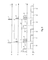
- the figure 3 shows, as a function of time t, four timing diagrams illustrating a mode of operation of the sighting system according to the invention.
- the figure 4 also shows four timing diagrams illustrating a variant of operation of the sighting system according to the invention.
- the day / night sighting system with integrated devometer 1, according to the present invention and shown in FIG. figure 1 is intended for the guidance in alignment of a missile 2 on a target 3. It comprises a single axis LL, at least approximately pointed at said target 3.
- the missile 2 is equipped with an optical transmitter 4 generating flashlights 5 in the near infrared.
- Said optical transmitter 4 may be a flash tag (xenon lamp, laser diode, ...) or a simple element reflecting light flashes from a fixed beacon to the system 1.
- the aiming system 1 comprises a single optical system of axis LL and, in the focal plane thereof, a planar infrared detector 7, at least approximately orthogonal to said axis LL of the system 1.
- a double bandpass filter 8 is disposed between the optical system 6 and the infrared detector 7.
- the infrared detector 7 comprises, for example, a matrix of photosensitive elements of indium antimonide or telluride of mercury and cadmium, disposed in a dewar connected to a cooling device not shown.
- the filter 8 can also be of the cooled type and it can be housed in the cooler of the detector 7.
- the infrared detector 7 comprises a high number of photosensitive elements, for example 640 ⁇ 512 or 1280 ⁇ 1024, and it can operate in "snapshot" mode, that is to say that all the photosensitive elements integrate at the same time the portion of the scene that 'they are watching.
- the detector 7 has a field of the order of 6 ° to 8 ° and an angular resolution at least as good as 0.3 mrad, preferably 0.1 mrad.
- the infrared detector 7 is able to operate in IWR mode, that is to say it can integrate an image while the previous image is read.
- the infrared detector 7 is sensitive both in the infrared medium corresponding to the spectral window of 3 to 5 ⁇ m in order to be able to form thermal images and in the near infrared emitted by the luminous chips 5.
- the spectral selectivity is ensured by the 8.
- the bandwidth of the filter 8 is precisely adapted to the emission spectral band of the light flashes 5, which allows to largely eliminate the radiation of the observed scene and thus to guarantee a high signal-to-noise ratio, during the image-taking of the flashes 5.
- the bandwidth of the filter 8 is precisely adapted to the spectral response of the detector 7, to allow thermal targeting with a good level of sensitivity.
- the aiming system 1 comprises an electronic command and processing unit 9 which makes it possible, in particular, to take images 3 'of the target 3 and images 5' (representative of the missile 2) of the fragments 5 emitted by the transmitter 4 by the infrared detector 7.
- a synchronization symbolized by the dashed line 10 in the figures) between the electronic block 9 and the transmitter 4 allows the taking of the images 5 'during the short duration of the flashlights 5 (from a few microseconds to a few dozens of microseconds).
- a display block 11 for example of the monitor type, is incorporated in the sighting system 1 and is capable of supplying an operator 1 2 with the thermal image in the mid-infrared of the scene in which the target 3 is located.
- the optical transmitter 4 comprises a source 13 (xenon lamp, laser diode, ...) generating the chips 5 and controlled by a triggering electronics 14, itself controlled by a sequencer 15 driven by a time base 16 .
- the electronic control and processing unit 9 comprises a device 9A for controlling the matrix detector 7 and a device 9B for image processing and deviation measurement.
- the device 9A includes a time base 17, connected to an image acquisition processor 18, which controls the sequencer 19 of the detector 7.
- the sequencer 19 controls the electronic implementation 20 of the latter.
- An interface electronics 21 allows the synchronization of images of the detector 7 with the light bursts 5, thanks to the link 10 existing between the transmitter 4 and the block 9.
- the synchronization link 10 can be established before firing the missile 2 and be maintained during the flight thereof by the stability of the time bases 16 and 17. It can also be established by microwave link or by a cable that runs as the advance of the missile 2 .
- the device 9B includes an image memory 22, connected to the detector 7, and an image processing processor 23 in connection with the memory 22 and controlling a calculator 24 for differential deviation between the missile 2 and the target 3.
- the calculator 24 controls a calculator 25 for guiding the missile 2.
- the device 9A opens an integration window i1 of a few tens of ⁇ s, allowing the detector 7 to integrate the scene that it observes through the optical system 6 and which includes the corresponding brightness 5 (see chronogram c).
- the device 9A opens another integration window i2, preferably identical to the integration window i1 but temporally very little offset from the corresponding top ⁇ .
- the image I2 corresponding to an integration window i2 thus represents the same scene as the associated image I1, but without the 5 'image of the brightness 5.
- the difference image I1-I2 formed in FIG. the device 9B includes only the image of the chip 5 and completely eliminates the scene in which are the target 3 and the missile 2, including any jammers that may be there.
- the device 9A opens long integration windows i3, for example of a duration of 0.5 ms to 5 ms, for forming images I3 of the scene comprising the target 3 and able to form the thermal images displayed on the display block 11.
- the images 5 'and 3' respectively representative of the missile 2 and of the target 3 are formed at very close times.
- the distance separating said images from said detector 7 is therefore known, which allows the computer 24 to perform the differential deviation between the missile 2 and the target 3 and to control accordingly the guidance computer 25. It is possible to overcome guiding errors from inadvertent movements applied to the sighting system 1 , both by the operator and by the firing of the missile 2. Moreover, thanks to such differential deviation, the operator can, before firing the missile 2, select precisely within the target 3 a point of desired impact, on which the missile will be guided.
- the missiles 2A and 2B can thus be guided towards the same target or on two different targets, by differential deviation measurements from the positions of the images of said missiles and said targets on said infrared detector 7.
Landscapes
- Engineering & Computer Science (AREA)
- Combustion & Propulsion (AREA)
- General Engineering & Computer Science (AREA)
- Physics & Mathematics (AREA)
- Chemical & Material Sciences (AREA)
- Electromagnetism (AREA)
- General Physics & Mathematics (AREA)
- Radar, Positioning & Navigation (AREA)
- Remote Sensing (AREA)
- Aiming, Guidance, Guns With A Light Source, Armor, Camouflage, And Targets (AREA)
- Closed-Circuit Television Systems (AREA)
- Optical Radar Systems And Details Thereof (AREA)
- Road Signs Or Road Markings (AREA)
- Led Device Packages (AREA)
- Photometry And Measurement Of Optical Pulse Characteristics (AREA)
- Paper (AREA)
- Position Fixing By Use Of Radio Waves (AREA)
- Iron Core Of Rotating Electric Machines (AREA)
- Transition And Organic Metals Composition Catalysts For Addition Polymerization (AREA)
- Diaphragms For Electromechanical Transducers (AREA)
- Organic Low-Molecular-Weight Compounds And Preparation Thereof (AREA)
Abstract
Description
La présente invention concerne un système de visée à écartomètre intégré. Un tel système est particulièrement approprié à la localisation de missiles en vol en vue de leur guidage sur une cible, telle qu'un véhicule blindé ou un bunker.The present invention relates to an integrated devometer sighting system. Such a system is particularly suitable for locating missiles in flight for guidance on a target, such as an armored vehicle or a bunker.
Par le document
- un détecteur optique comportant une matrice d'éléments photosensibles aptes à détecter lesdits éclats lumineux successifs ;
- un système optique, qui regarde la scène dans laquelle se trouvent la cible et ledit missile et dans le plan focal duquel est disposé ledit détecteur optique ;
- des moyens électroniques de commande dudit détecteur optique aptes à déclencher des prises de vue de ladite scène par ce dernier ; et
- des moyens aptes à synchroniser des prises d'images dudit détecteur optique avec lesdits éclats lumineux successifs.
- an optical detector comprising a matrix of photosensitive elements able to detect said successive flashes of light;
- an optical system, which looks at the scene in which the target and said missile are located and in the focal plane of which said optical detector is disposed;
- electronic control means of said optical detector capable of triggering shots of said scene by the latter; and
- means capable of synchronizing the taking of images of said optical detector with said successive flashes of light.
Ainsi, dans un tel écartomètre connu, la position dans ladite matrice du ou des éléments photosensibles excité(s) par lesdits éclats lumineux successifs est représentative de la position dudit missile par rapport à l'axe dudit système optique.Thus, in such a known deviometer, the position in said matrix of the photosensitive element (s) excited by said successive flashes is representative of the position of said missile relative to the axis of said optical system.
Lorsqu'un tel écartomètre est utilisé dans un poste de tir de missiles à guidage en alignement, on l'associe à un dispositif de visée de jour (lunette) et/ou à un dispositif de visée de nuit (caméra thermique) à l'usage de l'opérateur dudit poste de tir. On obtient ainsi un système de visée composite avec écartomètre permettant audit opérateur de suivre une cible avec l'un ou l'autre desdits dispositifs de visée suivant les conditions de luminosité, l'écartomètre fournissant des informations de position du missile en vol à des moyens de guidage de ce dernier vers ladite cible.When such a differential gauge is used in an alignment guided missile firing station, it is associated with a day sighting device (telescope) and / or a night vision device (thermal camera) at the same time. use of the operator of said firing station. This gives a system of composite aiming device with a distance gauge enabling said operator to follow a target with one or the other of said sighting devices according to the light conditions, the devometer providing information on the position of the missile in flight to means for guiding the latter towards said target.
Dans un tel système de visée composite, il existe donc une voie écartométrie et au moins une voie visée, chacune desdites voies ayant son propre système optique, son propre détecteur et sa propre électronique (visée thermique), ..., ce qui rend ledit système complexe, coûteux, lourd et volumineux. De tels inconvénients sont particulièrement désavantageux lorsque ledit système de visée composite doit être porté par l'opérateur.In such a composite aiming system, there is therefore a deviation measurement path and at least one target path, each of said pathways having its own optical system, its own detector and its own electronics (thermal aiming), ..., which makes said complex, expensive, heavy and bulky system. Such disadvantages are particularly disadvantageous when said composite sighting system is to be worn by the operator.
Ces inconvénients de complexité de coût, de masse et d'encombrement sont encore augmentés du fait qu'il est nécessaire de prévoir, pour la voie écartomètre, une voie optique à grand champ pour la prise en charge du missile par le poste de tir après lancement et une voie optique à champ réduit pour le guidage.These disadvantages of complexity of cost, mass and size are further increased because it is necessary to provide, for the deviometer path, a wide-field optical channel for the management of the missile by the firing station after launch and a reduced field optical path for guidance.
Par ailleurs, dans un tel système de visée composite, il est indispensable pour les performances que les axes des voies écartométrie et visée soient rigoureusement harmonisés et le restent pendant toute la durée de l'utilisation, ce qui nécessite des réglages de précision ou même un dispositif optique d'harmonisation supplémentaire et oblige à utiliser le système avec précaution, bien que les conditions d'utilisation ne le permettent généralement pas.Moreover, in such a composite aiming system, it is essential for the performances that the axes of the deviation and aiming paths are rigorously harmonized and remain so throughout the duration of the use, which requires precision adjustments or even a additional optical harmonization device and requires the use of the system with caution, although the conditions of use do not generally allow it.
De plus, le dispositif de visée de jour (lunette) forme une voie optique directe apte à transmettre une agression laser jusqu'à l'opérateur.In addition, the day-sighting device (telescope) forms a direct optical channel capable of transmitting laser aggression to the operator.
Enfin, du fait que, dans un tel système de visée composite avec écartomètre, le missile est asservi à la ligne de visée du dispositif de visée de jour ou à celle du dispositif de visée de nuit, le guidage du missile est très sensible aux mouvements intempestifs ou mal contrôlés que l'opérateur imprime audit système (par exemple lors du délestage du missile hors de son tube de lancement, lors du suivi d'une cible à fort défilement, gênes pendant la visée, etc ...). Il en résulte un guidage perturbé pour le missile, qui, éventuellement, peut même sortir du champ dudit système.Finally, because in such a composite aiming system with a deviation gauge, the missile is slaved to the line of sight of the day-sighting device or that of the night-sighting device, the missile guidance is very sensitive to movements. inopportune or poorly controlled that the operator prints to said system (for example during the unloading of the missile out of its launching tube, during the tracking of a high-scrolling target, annoying during the aiming, etc ...). This results in a disturbed guidance for the missile, which possibly can even out of the field of said system.
La présente invention a pour objet un système de visée à écartomètre intégré permettant de remédier aux inconvénients précités.The subject of the present invention is an integrated devometer sighting system making it possible to remedy the aforementioned drawbacks.
A cette fin, selon l'invention, le système de visée apte à être dirigé vers une cible et comportant un écartomètre du type rappelé ci-dessus est remarquable en ce que :
- ledit détecteur optique est un détecteur infrarouge sensible non seulement au proche infrarouge dans le spectre d'émission de l'émetteur optique associé au missile, mais encore au moyen infrarouge compris entre 3 et 5 micromètres ;
- lesdits éléments photosensibles dudit détecteur infrarouge présentent, au moyen d'une optique appropriée, une résolution angulaire au moins aussi bonne que 0,3 mrad, de préférence aussi bonne que 0,1 mrad ;
- lesdits moyens électroniques de commande déclenchent des prises de vue de ladite scène par ledit détecteur infrarouge non seulement en synchronisme avec lesdits éclats lumineux, mais encore dans les intervalles entre lesdits éclats lumineux successifs ; et
- des moyens de visualisation sont prévus pour visualiser les images résultant des prises de vue réalisées dans lesdits intervalles entre lesdits éclats lumineux successifs.
- said optical detector is an infrared detector sensitive not only to the near infrared in the emission spectrum of the optical transmitter associated with the missile, but also to the infrared medium of between 3 and 5 micrometers;
- said photosensitive elements of said infrared detector have, by means of appropriate optics, an angular resolution at least as good as 0.3 mrad, preferably as good as 0.1 mrad;
- said electronic control means triggers shots of said scene by said infrared detector not only in synchronism with said light flashes, but also in the intervals between said successive light flashes; and
- display means are provided for displaying the images resulting from the shots taken in said intervals between said successive light flashes.
Ainsi, dans le système conforme à la présente invention, les images dans le moyen infrarouge constituent des images thermiques de la scène observée, aptes à servir à la visée de jour et à la visée de nuit. Le dispositif de visée de jour et le dispositif de visée de nuit ne sont donc plus nécessaires.Thus, in the system according to the present invention, the images in the medium infrared are thermal images of the observed scene, suitable for daytime aiming and night aiming. The day sighting device and the night sighting device are therefore no longer necessary.
Le système selon l'invention ne comporte donc plus qu'une seule voie pour les fonctions localisation, visée de jour et visée de nuit, de sorte que ses constituants optiques, électroniques et mécaniques sont nettement simplifiés, plus compacts et plus légers, ce qui permet d'obtenir un poste de tir aisément portable par un fantassin et nettement moins cher que les postes de tir actuels. L'harmonisation des voies visée jour/nuit et de la voie localisation est parfaite, puisqu'il n'y a plus qu'un seul axe optique, ce qui élimine tout défaut résiduel et évite ainsi une architecture opto-mécanique complexe pour garantir les performances d'harmonisation, notamment en température, ou un dispositif de correction en température, tels que cela était nécessaire dans les solutions antérieures. La suppression de tout défaut d'harmonisation (biais) entre la visée et le guidage améliore la précision de guidage du système.The system according to the invention therefore has only one channel for the localization, sighting and night aiming functions, so that its optical, electronic and mechanical components are clearly simplified, more compact and lighter, which makes it possible to obtain an easily portable shooting range by an infantryman and much less expensive than the current firing points. Harmonization of the day / night channels and the localization channel is perfect, since there is only one optical axis, which eliminates any residual defects and thus avoids a complex opto-mechanical architecture to guarantee harmonization performance, especially in temperature, or a temperature correction device, as was necessary in previous solutions. Removing any misalignment (bias) between sighting and guidance improves the guidance accuracy of the system.
Par ailleurs, du fait que la matrice du détecteur infrarouge comporte un grand nombre d'éléments photosensibles (pixels) de haute résolution (au moins 388 x 284, mais de préférence 640 x 512 et même 1280 x 1024 pour assurer une bonne identification de la cible avant tir et une précision de guidage élevée), le système selon l'invention peut ne comporter qu'un seul champ de vue (de l'ordre de 6° à 8°), servant à la fois à la prise en charge du missile lors de son lancement et au guidage dudit missile vers la cible.Moreover, because the matrix of the infrared detector comprises a large number of photosensitive elements (pixels) of high resolution (at least 388 x 284, but preferably 640 x 512 and even 1280 x 1024 to ensure a good identification of the target before shooting and a high guiding precision), the system according to the invention may comprise only one field of view (of the order of 6 ° to 8 °), serving both to support the missile during its launch and guiding said missile towards the target.
De plus, dans le système selon l'invention, il n'existe aucune voie de visée directe, de sorte que l'oeil de l'opérateur est protégé contre les agressions laser.In addition, in the system according to the invention, there is no direct sighting path, so that the eye of the operator is protected against laser attack.
De préférence, la matrice dudit détecteur infrarouge est composée d'éléments photosensibles en antimoniure d'indium ou en tellurure de mercure et de cadmium.Preferably, the matrix of said infrared detector is composed of photosensitive elements of indium antimonide or telluride of mercury and cadmium.
Avantageusement, le temps séparant une prise de vue dans un intervalle entre deux éclats lumineux successifs et une prise de vue en synchronisme avec l'un de ces derniers est au plus égal à 15 millisecondes. Ainsi, ces deux prises de vue peuvent être considérées comme simultanées.Advantageously, the time separating a shot in an interval between two successive flashes of light and a synchronous shooting with one of these is at most equal to 15 milliseconds. Thus, these two shots can be considered simultaneous.
De façon connue, ledit détecteur infrarouge forme les images par intégration et lecture consécutive et le temps d'intégration des images correspondant à des prises de vue en synchronisme avec lesdits éclats lumineux est choisi au plus égal à 200 microsecondes, alors que le temps d'intégration des images correspondant à des prises de vue dans les intervalles entre lesdits éclats lumineux successifs est avantageusement compris entre 1 et 5 millisecondes.In known manner, said infrared detector forms the images by integration and consecutive reading and the integration time of the images corresponding to shots in synchronism with said light flashes is chosen at most equal to 200 microseconds, while the time of integration of images corresponding to shots in the intervals between said successive flashes is advantageously between 1 and 5 milliseconds.
De préférence, ledit détecteur infrarouge fonctionne en mode IWR (Integrate While Read) de sorte que, pendant la lecture de chaque image correspondant à une prise de vue en synchronisme avec un éclat lumineux, lesdits moyens électroniques de commande peuvent déclencher une prise de vue additionnelle de ladite scène donnant naissance à une image additionnelle au moins approximativement identique (sauf en ce qui concerne l'image dudit éclat lumineux) à ladite image correspondant à une prise de vue en synchronisme avec un éclat lumineux. Il est alors prévu un processeur d'images apte à comparer cette dernière image et ladite image additionnelle pour en déduire sans ambiguïté la position de l'image dudit missile sur ledit détecteur. En effet, la différence entre ces deux images permet de ne conserver, dans l'image de différence, que les informations concernant l'éclat lumineux (c'est-à-dire le missile) tout en éliminant les sources de brouillage et les fausses émissions (effets solaires par exemple).Preferably, said infrared detector operates in IWR mode (Integrate While Read) so that, during the reading of each image corresponding to a shooting in synchronism with a luminous flash, said electronic control means can trigger an additional shooting said scene giving rise to an additional image at least approximately identical (except for the image of said luminous flash) to said image corresponding to a shooting in synchronism with a luminous flash. There is then provided an image processor adapted to compare the latter image and said additional image to unambiguously deduce the position of the image of said missile on said detector. Indeed, the difference between these two images makes it possible to keep, in the image of difference, only the information concerning the luminous flash (that is to say the missile) while eliminating the sources of jamming and false emissions (solar effects for example).
On remarquera que, grâce à la présente invention, on réalise l'acquisition quasi-simultanée, sur ledit détecteur infrarouge, des images desdits éclats et de la cible, ce qui permet la poursuite automatique différentielle du missile sur la cible, évitant ainsi les inconvénients dus aux mouvements de l'opérateur, notamment pour les missiles tirés à l'épaule. Le système conforme à la présente invention comporte alors un calculateur calculant l'écartométrie différentielle entre ledit missile et ladite cible à partir d'informations délivrées par ledit détecteur infrarouge et relatives aux positions respectives, sur ladite matrice, des images correspondant à des prises de vue en synchronisme avec lesdits éclats lumineux successifs et des images correspondant à des prises de vue dans les intervalles entre lesdits éclats lumineux.It will be noted that, thanks to the present invention, the quasi-simultaneous acquisition, on said infrared detector, of the images of said chips and of the target, which allows the differential automatic tracking of the missile on the target, thus avoiding the disadvantages due to movements of the operator, especially for missiles fired at the shoulder. The system according to the present invention then comprises a calculator calculating the differential deviation measurement between said missile and said target on the basis of information delivered by said infrared detector and relative to the respective positions, on said matrix, of images corresponding to shots in synchronism with said successive flashes of light and images corresponding to shots in the intervals between said luminous flashes.
Lesdits moyens aptes à synchroniser les prises d'images dudit détecteur infrarouge avec lesdits éclats lumineux successifs peuvent être temporaires ou permanents. Par ailleurs, lesdits éclats lumineux peuvent être déclenchés à partir dudit missile ou à partir dudit détecteur infrarouge. Dans ce dernier cas, lesdits moyens électroniques de commande du détecteur infrarouge peuvent être aptes à commander les émetteurs optiques d'au moins deux missiles afin que lesdits émetteurs optiques engendrent des suites imbriquées d'éclats lumineux.Said means capable of synchronizing the taking of images of said infrared detector with said successive flashes of light may be temporary or permanent. Moreover, said light flashes can be triggered from said missile or from said infrared detector. In the latter case, said electronic control means of the infrared detector may be able to control the optical emitters of at least two missiles so that said optical emitters generate nested sequences of light flashes.
Les figures du dessin annexé feront bien comprendre comment l'invention peut être réalisée. Sur ces figures, des références identiques désignent des éléments semblables.The figures of the appended drawing will make it clear how the invention can be realized. In these figures, identical references designate similar elements.
La
La
La
La
Le système de visée jour/nuit à écartomètre intégré 1, conforme à la présente invention et représenté sur la
Le missile 2 est équipé d'un émetteur optique 4 engendrant des éclats lumineux 5 dans le proche infrarouge. Ledit émetteur optique 4 peut être une balise à éclats (lampe au xénon, diode laser, ...) ou bien un simple élément réfléchissant des éclats lumineux d'une balise fixe vers le système 1.The
Le système de visée 1 comporte un unique système optique d'axe L-L et, dans le plan focal de celui-ci, un détecteur infrarouge plan 7, au moins approximativement orthogonal audit axe L-L du système 1. Un filtre 8 double passe-bande est disposé entre le système optique 6 et le détecteur infrarouge 7.The aiming
Le détecteur infrarouge 7 comporte, par exemple, une matrice d'éléments photosensibles en antimoniure d'indium ou en tellurure de mercure et de cadmium, disposée dans un dewar relié à un dispositif de refroidissement non représenté. Le filtre 8 peut également être du type refroidi et il peut être logé dans le refroidisseur du détecteur 7.The
Le détecteur infrarouge 7 comporte un nombre élevé d'éléments photosensibles, par exemple 640x512 ou 1280x1024, et il peut fonctionner en mode "snapshot", c'est-à-dire que tous les éléments photosensibles intègrent au même moment la portion de scène qu'ils regardent. Le détecteur 7 présente un champ de l'ordre de 6° à 8° et une résolution angulaire au moins aussi bonne que 0,3 mrad, de préférence 0,1 mrad.The
De plus, le détecteur infrarouge 7 est apte à fonctionner en mode IWR, c'est-à-dire qu'il peut intégrer une image alors que l'image précédente est en lecture.In addition, the
Le détecteur infrarouge 7 est sensible, à la fois, dans le moyen infrarouge correspondant à la fenêtre spectrale de 3 à 5 µm pour pouvoir former des images thermiques et dans le proche infrarouge émis par les éclats lumineux 5. La sélectivité spectrale est assurée par le filtre 8. Dans le proche infrarouge, la bande passante du filtre 8 est adaptée de façon précise à la bande spectrale d'émission des éclats lumineux 5, ce qui permet d'éliminer en grande partie le rayonnement de la scène observée et donc garantir un rapport signal/bruit élevé, pendant les prises d'image des éclats lumineux 5. Dans le moyen infrarouge, la bande passante du filtre 8 est adaptée de façon précise à la réponse spectrale du détecteur 7, pour permettre la visée thermique avec un bon niveau de sensibilité.The
Le système de visée 1 comporte un bloc électronique de commande et de traitement 9 permettant notamment la prise d'images 3' de la cible 3 et d'images 5' (représentatives du missile 2) des éclats 5 émis par l'émetteur 4 par le détecteur infrarouge 7. Une synchronisation (symbolisée par la ligne en pointillés 10 sur les figures) entre le bloc électronique 9 et l'émetteur 4 permet la prise des images 5' pendant la courte durée des éclats lumineux 5 (de quelques microsecondes à quelques dizaines de microsecondes).The aiming
Un bloc de visualisation 11, par exemple du type moniteur, est incorporé au système de visée 1 et est apte à fournir à un opérateur 1 2 l'image thermique dans le moyen infrarouge de la scène dans laquelle se trouve la cible 3.A
Comme l'illustre la
Dans le mode de réalisation de la
Le dispositif 9A comporte une base de temps 17, reliée à un processeur d'acquisition d'images 18, qui pilote le séquenceur 19 du détecteur 7. Le séquenceur 19 commande l'électronique de mise en oeuvre 20 de ce dernier. Une électronique d'interface 21 permet la synchronisation de prises d'images du détecteur 7 avec les éclats lumineux 5, grâce à la liaison 10 existant entre l'émetteur 4 et le bloc 9. La liaison de synchronisation 10 peut être établie avant tir du missile 2 et être maintenue pendant le vol de celui-ci par la stabilité des bases de temps 16 et 17. Elle peut également être établie par liaison hertzienne ou par un câble qui se déroule au fur et à mesure de l'avance du missile 2.The
Le dispositif 9B comporte une mémoire d'images 22, reliée au détecteur 7, et un processeur de traitement d'images 23 en liaison avec la mémoire 22 et commandant un calculateur 24 d'écartométrie différentielle entre le missile 2 et la cible 3. Le calculateur 24 commande un calculateur 25 de guidage du missile 2.The
Sur les chronogrammes de la
En synchronisme avec l'émission de chaque top τ, le dispositif 9A ouvre une fenêtre d'intégration i1 de quelques dizaines de µs, permettant au détecteur 7 d'intégrer la scène qu'il observe à travers le système optique 6 et qui comporte l'éclat 5 correspondant (voir le chronogramme c).In synchronism with the emission of each top τ, the
Pendant la lecture de chaque image I1, intégrée pendant une fenêtre d'intégration i1, le dispositif 9A ouvre une autre fenêtre d'intégration i2, de préférence identique à la fenêtre d'intégration i1 mais temporellement très peu décalée par rapport au top τ correspondant. L'image I2 correspondant à une fenêtre d'intégration i2 représente donc la même scène que l'image I1 associée, toutefois sans l'image 5' de l'éclat 5. Par suite, l'image de différence I1-I2 formée dans le dispositif 9B ne comporte que l'image de l'éclat 5 et élimine complètement la scène dans laquelle se trouvent la cible 3 et le missile 2, y compris les éventuels brouilleurs qui pourraient s'y trouver.During the reading of each image I1, integrated during an integration window i1, the
Par ailleurs, à une distance temporelle ΔT des fenêtres d'intégration i1 (au plus de 15 ms), le dispositif 9A ouvre des fenêtres d'intégration longues i3, par exemple d'une durée de 0,5 ms à 5 ms, pour former des images I3 de la scène comportant la cible 3 et aptes à former les images thermiques affichées sur le bloc de visualisation 11.Moreover, at a temporal distance ΔT of the integration windows i1 (at most 15 ms), the
Ainsi, sur le détecteur infrarouge 7, on forme, à des instants très rapprochés, les images 5' et 3' représentatives respectivement du missile 2 et de la cible 3. On connaît donc la distance séparant lesdites images sur ledit détecteur 7, ce qui permet au calculateur 24 d'effectuer l'écartométrie différentielle entre le missile 2 et la cible 3 et de commander en conséquence le calculateur de guidage 25. On peut donc s'affranchir des erreurs de guidage provenant de mouvements intempestifs appliqués au système de visée 1, aussi bien par l'opérateur que par le tir du missile 2. De plus, grâce à une telle écartométrie différentielle, l'opérateur peut, avant tir du missile 2, sélectionner précisément à l'intérieur de la cible 3 un point d'impact souhaité, sur lequel le missile sera guidé.Thus, on the
Dans l'exemple de fonctionnement illustré par les chronogrammes de la
- la base de temps 17 émet des tops successifs de déclenchement tA pour
la source 13 d'un missile 2A (non représenté) émettant des éclats 5A ; - la base de temps 17 émet des tops successifs de déclenchement tB, intercalés dans les tops tA et déclenchant la
source 13 d'un missile 2B (non représenté) émettant des éclats 5B ; - de façon analogue à ce qui a été décrit ci-dessus à propos des fenêtres d'intégration i1, i2 et des images I1, I2, le détecteur infrarouge 7 :
- ouvre des fenêtres d'intégration i1A pour former des images I1A de la scène dans laquelle se trouve le missile 2A pendant les éclats 5A,
- ouvre des fenêtres d'intégration i2A pour former des images I2A de la scène dans laquelle se trouve le missile 2A entre les éclats 5A,
- forme des images de différence I1A-I2A,
- ouvre des fenêtres d'intégration i1B pour former des images I1B de la scène dans laquelle se trouve le missile 2B pendant les éclats 5B,
- ouvre des fenêtres d'intégration i2B pour former des images I2B de la scène dans laquelle se trouve le missile 2B entre les éclats 5B,
- forme les images de différence I1B-I2B, et
- de façon analogue à ce qui a été décrit en regard de la
figure 3 , le détecteur infrarouge 7 forme les images thermiques I3 de la scène, intégrées pendant les fenêtres d'intégration intermédiaires i3.
- the
time base 17 emits successive triggering tops tA for thesource 13 of a missile 2A (not shown) emittingsplinters 5A; - the
time base 17 emits successive trigger tops tB, interspersed in the tops tA and triggering thesource 13 of a missile 2B (not shown) emittingsplinters 5B; - analogously to what has been described above with regard to the integration windows i1, i2 and images I1, I2, the infrared detector 7:
- opens integration windows i1A to form images I1A of the scene in which the missile 2A is located during
splinters 5A, - opens integration windows i2A to form I2A images of the scene in which the missile 2A is located between the
fragments 5A, - form difference images I1A-I2A,
- opens integration windows i1B to form images I1B of the scene in which the missile 2B is located during
splinters 5B, - opens i2B integration windows to form I2B images of the scene in which missile 2B is located between
splinters 5B, - forms the difference images I1B-I2B, and
- opens integration windows i1A to form images I1A of the scene in which the missile 2A is located during
- similar to what has been described with regard to the
figure 3 , theinfrared detector 7 forms the thermal images I3 of the scene, integrated during the intermediate integration windows i3.
A la lumière de ce qui a été décrit précédemment, on comprendra que les missiles 2A et 2B peuvent ainsi être guidés vers une même cible ou sur deux cibles différentes, par écartométrie différentielle à partir des positions des images desdits missiles et desdites cibles sur ledit détecteur infrarouge 7.In the light of what has been described above, it will be understood that the missiles 2A and 2B can thus be guided towards the same target or on two different targets, by differential deviation measurements from the positions of the images of said missiles and said targets on said
Claims (16)
caractérisé en ce que la résolution angulaire desdits éléments photosensibles est au moins aussi bonne que 0,1 mrad.System according to claim 1,
characterized in that the angular resolution of said photosensitive elements is at least as good as 0.1 mrad.
caractérisé en ce que ladite matrice du détecteur infrarouge (7) comporte au moins 640 x 512 éléments photosensibles.System according to one of claims 1 or 2,
characterized in that said matrix of the infrared detector (7) comprises at least 640 x 512 photosensitive elements.
caractérisé en ce que ladite matrice du détecteur infrarouge (7) comporte 1280 x 1024 éléments photosensibles.System according to claim 3,
characterized in that said matrix of the infrared detector (7) comprises 1280 x 1024 photosensitive elements.
caractérisé en ce que la matrice dudit détecteur infrarouge (7) est composée d'éléments photosensibles en antimoniure d'indium.System according to one of claims 1 to 4,
characterized in that the matrix of said infrared detector (7) is composed of photosensitive elements of indium antimonide.
caractérisé en ce que la matrice dudit détecteur infrarouge (7) est composée d'éléments photosensibles en tellurure de mercure et de cadmium.System according to one of claims 1 to 4,
characterized in that the matrix of said infrared detector (7) is composed of photosensitive elements of mercury telluride and cadmium.
caractérisé en ce que le temps séparant une prise de vue dans un intervalle entre deux éclats lumineux successifs (5) et une prise de vue en synchronisme avec l'un de ces derniers est au plus égal à 15 millisecondes.System according to one of Claims 1 to 6,
characterized in that the time separating a shot in a gap between two successive flashes (5) and a shooting in synchronism with one of these is at most equal to 15 milliseconds.
caractérisé en ce que le temps d'intégration des images correspondant à des prises de vue en synchronisme avec lesdits éclats lumineux est au plus égal à 200 microsecondes.System according to one of claims 1 to 7,
characterized in that the integration time of the images corresponding to shots in synchronism with said light flashes is at most equal to 200 microseconds.
caractérisé en ce que le temps d'intégration des images correspondant à des prises de vue dans les intervalles entre lesdits éclats lumineux successifs est compris entre 1 et 5 millisecondes.System according to one of claims 1 to 8,
characterized in that the integration time of the images corresponding to shots in the intervals between said successive flashes is between 1 and 5 milliseconds.
caractérisé en ce que, pendant la lecture de chaque image correspondant à une prise de vue en synchronisme avec un éclat lumineux, lesdits moyens électroniques de commande (9) déclenchent une prise de vue additionnelle de ladite scène donnant naissance à une image additionnelle au moins approximativement identique à ladite image correspondant à une prise de vue en synchronisme avec un éclat lumineux et en ce qu'il est prévu un processeur d'images (11) apte à comparer cette dernière image et ladite image additionnelle pour en déduire la position de l'image dudit missile sur ledit détecteur.System according to one of claims 1 to 6, wherein said infrared detector (7) forms images by integration and consecutive reading,
characterized in that , during the reading of each image corresponding to a shot in synchronism with a luminous flash, said electronic control means (9) triggers an additional shot of said scene giving rise to an additional image at least approximately identical to said image corresponding to a shot in synchronism with a flash of light and in that there is provided an image processor (11) adapted to compare the latter image and said additional image to deduce the position of the image of said missile on said detector.
caractérisé en ce qu'il comporte un calculateur (24) calculant l'écartométrie différentielle entre ledit missile (2) et ladite cible (3) à partir d'informations délivrées par ledit détecteur infrarouge et relatives aux positions respectives, dans ladite matrice, des images (5') correspondant à des prises de vue en synchronisme avec lesdits éclats lumineux successifs (5) et des images (3') correspondant à des prises de vue dans les intervalles entre lesdits éclats lumineux (5).System according to any one of claims 1 to 10,
characterized in that it comprises a calculator (24) calculating the differential deviation measurement between said missile (2) and said target (3) from information supplied by said infrared detector and relative to the respective positions, in said matrix, of images (5 ') corresponding to shots in synchronism with said successive flashes (5) and images (3') corresponding to shots in the intervals between said flashes (5).
caractérisé en ce que lesdits moyens (10) aptes à synchroniser les prises d'images dudit détecteur infrarouge (7) avec lesdits éclats lumineux successifs (5) sont temporaires.System according to one of Claims 1 to 11,
characterized in that said means (10) capable of synchronizing the images of said infrared detector (7) with said successive light bursts (5) are temporary.
caractérisé en ce que lesdits moyens (10) aptes à synchroniser les prises d'images dudit détecteur infrarouge (7) avec lesdits éclats lumineux successifs (5) sont permanents.System according to one of Claims 1 to 11,
characterized in that said means (10) capable of synchronizing the imaging of said infrared detector (7) with said successive light flashes (5) are permanent.
caractérisé en ce que lesdits éclats lumineux (5) sont déclenchés à partir dudit missile (2).System according to any one of claims 1 to 13,
characterized in that said light flashes (5) are triggered from said missile (2).
caractérisé en ce que lesdits éclats lumineux (5) sont déclenchés à partir des moyens électroniques de commande (9) dudit détecteur infrarouge (7).System according to any one of claims 1 to 13,
characterized in that said light flashes (5) are triggered from the electronic control means (9) of said infrared detector (7).
caractérisé en ce que lesdits moyens électroniques de commande (9) sont aptes à commander les émetteurs optiques (4) d'au moins deux missiles afin que lesdits émetteurs optiques (4) engendrent des suites imbriquées d'éclats lumineux (5A, 5B).System according to claim 15,
characterized in that said electronic control means (9) are able to control the optical transmitters (4) of at least two missiles so that said optical transmitters (4) generate interleaved sequences of light flashes (5A, 5B).
Applications Claiming Priority (1)
| Application Number | Priority Date | Filing Date | Title |
|---|---|---|---|
| FR0610165A FR2908874B1 (en) | 2006-11-21 | 2006-11-21 | INTEGRATED ECARTOMETER REFERENCE SYSTEM. |
Publications (2)
| Publication Number | Publication Date |
|---|---|
| EP1925902A1 true EP1925902A1 (en) | 2008-05-28 |
| EP1925902B1 EP1925902B1 (en) | 2009-05-13 |
Family
ID=38169313
Family Applications (1)
| Application Number | Title | Priority Date | Filing Date |
|---|---|---|---|
| EP07291366A Not-in-force EP1925902B1 (en) | 2006-11-21 | 2007-11-15 | Sighting system with built-in deviation indicator |
Country Status (8)
| Country | Link |
|---|---|
| US (1) | US8022343B2 (en) |
| EP (1) | EP1925902B1 (en) |
| AT (1) | ATE431537T1 (en) |
| DE (1) | DE602007001124D1 (en) |
| ES (1) | ES2324687T3 (en) |
| FR (1) | FR2908874B1 (en) |
| IL (1) | IL198280A (en) |
| WO (1) | WO2008062114A1 (en) |
Cited By (3)
| Publication number | Priority date | Publication date | Assignee | Title |
|---|---|---|---|---|
| FR2954586A1 (en) * | 2009-12-23 | 2011-06-24 | Thales Sa | MATRIX ECARTOMETER TASK DETECTION DEVICE. |
| EP2515066A1 (en) | 2011-04-21 | 2012-10-24 | Thales | Differential steering device by active laser imaging |
| RU2490581C2 (en) * | 2011-11-22 | 2013-08-20 | Михаил Витальевич Головань | Automated operator viewing system |
Families Citing this family (10)
| Publication number | Priority date | Publication date | Assignee | Title |
|---|---|---|---|---|
| CN102132290A (en) | 2008-06-26 | 2011-07-20 | 前视红外系统公司 | Emitter tracking system |
| US8274425B2 (en) * | 2010-12-29 | 2012-09-25 | Raytheon Company | Single channel semi-active radar seeker |
| FI124434B (en) * | 2012-10-31 | 2014-08-29 | Metso Automation Oy | Method and apparatus for web monitoring |
| WO2014078811A1 (en) | 2012-11-16 | 2014-05-22 | Flir Systems, Inc. | Synchronized infrared beacon / infrared detection system |
| US9555899B2 (en) * | 2014-03-27 | 2017-01-31 | The United States Of America As Represented By The Secretary Of The Navy | Mobile arresting system |
| DE102015010276A1 (en) * | 2014-12-19 | 2016-06-23 | Mbda Deutschland Gmbh | A method and apparatus for locally stabilizing a radiation spot on a remote target |
| EP3640590B1 (en) | 2018-10-17 | 2021-12-01 | Trimble Jena GmbH | Surveying apparatus for surveying an object |
| EP3640677B1 (en) | 2018-10-17 | 2023-08-02 | Trimble Jena GmbH | Tracker of a surveying apparatus for tracking a target |
| US10972648B2 (en) * | 2018-12-31 | 2021-04-06 | Flir Surveillance, Inc. | Pulse detection and synchronized pulse imaging systems and methods |
| EP3696498A1 (en) | 2019-02-15 | 2020-08-19 | Trimble Jena GmbH | Surveying instrument and method of calibrating a survey instrument |
Citations (5)
| Publication number | Priority date | Publication date | Assignee | Title |
|---|---|---|---|---|
| EP0206912A1 (en) | 1985-06-17 | 1986-12-30 | AEROSPATIALE Société Nationale Industrielle | Position finding system for a moving object |
| EP0425355A1 (en) * | 1989-10-23 | 1991-05-02 | AEROSPATIALE Société Nationale Industrielle | Position finding system for a moving object |
| EP0633457A1 (en) * | 1993-07-05 | 1995-01-11 | AEROSPATIALE Société Nationale Industrielle | Photosensitive element and apparatus for the detection of light pulses |
| EP0740123A1 (en) * | 1995-04-24 | 1996-10-30 | Aerospatiale Societe Nationale Industrielle | System for determining the location and the roll angle of a moving body |
| US20020154293A1 (en) * | 2001-04-19 | 2002-10-24 | Wells Michael L. | Solid state modulated beacon tracking system |
Family Cites Families (21)
| Publication number | Priority date | Publication date | Assignee | Title |
|---|---|---|---|---|
| US4040744A (en) * | 1973-10-05 | 1977-08-09 | General Dynamics | Multiple spectrum co-axial optical sight and closed loop gun control system |
| US4419012A (en) * | 1979-09-11 | 1983-12-06 | Elliott Brothers (London) Limited | Position measuring system |
| US4424943A (en) * | 1981-05-04 | 1984-01-10 | Hughes Aircraft Company | Tracking system |
| SE455539B (en) * | 1986-05-23 | 1988-07-18 | Electrolux Ab | ELECTROOPTIC POSITION KNOWLEDGE SYSTEM FOR A PLAN REALLY FORMULA, PREFERRED A MOBILE ROBOT |
| FR2602057B1 (en) * | 1986-07-22 | 1988-11-04 | Matra | OPTICAL DISTANCE MEASUREMENT METHOD AND DEVICE |
| DE3701296C1 (en) * | 1987-01-17 | 1988-05-11 | Messerschmitt Boelkow Blohm | Arrangement for determining the position of a laser beam in a scattering medium |
| GB2282722B (en) * | 1987-07-30 | 1995-08-09 | Buck Chem Tech Werke | Infra-red search head for the location of enemy helicopters |
| NO164946C (en) * | 1988-04-12 | 1990-11-28 | Metronor As | OPTO-ELECTRONIC SYSTEM FOR EXACTLY MEASURING A FLAT GEOMETRY. |
| US4932777A (en) * | 1988-09-30 | 1990-06-12 | The United States Of America As Represented By The Administrator Of The National Aeronautics And Space Administration | Electro-optical spin measurement system |
| US5023845A (en) * | 1988-10-31 | 1991-06-11 | The United States Of America As Represented By The Secretary Of The Navy | Embedded fiber optic beam displacement sensor |
| FR2643723B1 (en) * | 1989-02-24 | 1991-07-26 | Sodern | DEVICE FOR DETERMINING THE DIRECTION OF THE ENERGY CENTER OF A LIGHT OBJECT |
| US5085507A (en) * | 1989-12-27 | 1992-02-04 | Texas Instruments Incorporated | Device for three dimensional tracking of an object |
| FR2672988A1 (en) * | 1991-02-15 | 1992-08-21 | Sodern | METHOD FOR MEASURING THE PRECISE POSITION OF THE ENERGY CENTER OF A TASK IMAGE OF A LIGHT OBJECT ON A PHOTOSENSITIVE DETECTOR |
| FR2672989A1 (en) * | 1991-02-15 | 1992-08-21 | Sodern | DEVICE FOR DETERMINING THE DIRECTION OF A LOW - BRIGHT EMISSIVE SOURCE AND ITS APPLICATION TO THE STELLAR VISEE. |
| JPH07234105A (en) * | 1994-02-23 | 1995-09-05 | Wacom Co Ltd | Light spot position measuring method |
| FR2736146B1 (en) * | 1995-06-28 | 1997-08-22 | Aerospatiale | GUIDANCE SYSTEM FOR ALIGNING A MISSILE ON A TARGET |
| FR2753785B1 (en) * | 1996-09-25 | 1998-11-13 | SELF-DIRECTING A FLYING BODY | |
| FR2848362B1 (en) * | 2002-12-10 | 2006-04-07 | Mbda France | METHOD AND DEVICE FOR REALIZING OPTICAL BONDING BY LASER PULSES |
| FR2857088B1 (en) * | 2003-07-04 | 2005-09-16 | Mbda France | ROTATING MISSILE EMITTING LIGHT PULSES. |
| FR2874434B1 (en) * | 2004-08-20 | 2006-11-17 | Mbda France Sa | METHOD AND DEVICE FOR REALIZING OPTICAL BINDING BY LIGHT BLINDS |
| IL173221A0 (en) * | 2006-01-18 | 2007-07-04 | Rafael Advanced Defense Sys | Devics |
-
2006
- 2006-11-21 FR FR0610165A patent/FR2908874B1/en not_active Expired - Fee Related
-
2007
- 2007-11-15 US US12/513,489 patent/US8022343B2/en not_active Expired - Fee Related
- 2007-11-15 DE DE602007001124T patent/DE602007001124D1/en not_active Expired - Fee Related
- 2007-11-15 WO PCT/FR2007/001876 patent/WO2008062114A1/en active Application Filing
- 2007-11-15 AT AT07291366T patent/ATE431537T1/en not_active IP Right Cessation
- 2007-11-15 ES ES07291366T patent/ES2324687T3/en active Active
- 2007-11-15 EP EP07291366A patent/EP1925902B1/en not_active Not-in-force
-
2009
- 2009-04-21 IL IL198280A patent/IL198280A/en active IP Right Grant
Patent Citations (6)
| Publication number | Priority date | Publication date | Assignee | Title |
|---|---|---|---|---|
| EP0206912A1 (en) | 1985-06-17 | 1986-12-30 | AEROSPATIALE Société Nationale Industrielle | Position finding system for a moving object |
| US4710028A (en) | 1985-06-17 | 1987-12-01 | Aerospatiale Societe Nationale Industrielle | System for locating a body in motion |
| EP0425355A1 (en) * | 1989-10-23 | 1991-05-02 | AEROSPATIALE Société Nationale Industrielle | Position finding system for a moving object |
| EP0633457A1 (en) * | 1993-07-05 | 1995-01-11 | AEROSPATIALE Société Nationale Industrielle | Photosensitive element and apparatus for the detection of light pulses |
| EP0740123A1 (en) * | 1995-04-24 | 1996-10-30 | Aerospatiale Societe Nationale Industrielle | System for determining the location and the roll angle of a moving body |
| US20020154293A1 (en) * | 2001-04-19 | 2002-10-24 | Wells Michael L. | Solid state modulated beacon tracking system |
Cited By (6)
| Publication number | Priority date | Publication date | Assignee | Title |
|---|---|---|---|---|
| FR2954586A1 (en) * | 2009-12-23 | 2011-06-24 | Thales Sa | MATRIX ECARTOMETER TASK DETECTION DEVICE. |
| WO2011076480A1 (en) * | 2009-12-23 | 2011-06-30 | Thales | Device for detecting laser spot with matrix deviometer |
| US9964622B2 (en) | 2009-12-23 | 2018-05-08 | Thales | Device for detecting laser spot with matrix deviometer having a readout circuit and a matrix of photodiodes |
| EP2515066A1 (en) | 2011-04-21 | 2012-10-24 | Thales | Differential steering device by active laser imaging |
| FR2974432A1 (en) * | 2011-04-21 | 2012-10-26 | Thales Sa | LASER ACTIVE IMAGING DIFFERENTIAL GUIDING DEVICE |
| RU2490581C2 (en) * | 2011-11-22 | 2013-08-20 | Михаил Витальевич Головань | Automated operator viewing system |
Also Published As
| Publication number | Publication date |
|---|---|
| IL198280A0 (en) | 2009-12-24 |
| FR2908874B1 (en) | 2009-01-23 |
| US8022343B2 (en) | 2011-09-20 |
| ATE431537T1 (en) | 2009-05-15 |
| EP1925902B1 (en) | 2009-05-13 |
| DE602007001124D1 (en) | 2009-06-25 |
| US20100012765A1 (en) | 2010-01-21 |
| FR2908874A1 (en) | 2008-05-23 |
| IL198280A (en) | 2014-05-28 |
| WO2008062114A1 (en) | 2008-05-29 |
| ES2324687T3 (en) | 2009-08-12 |
Similar Documents
| Publication | Publication Date | Title |
|---|---|---|
| EP1925902B1 (en) | Sighting system with built-in deviation indicator | |
| EP0206912B1 (en) | Position finding system for a moving object | |
| EP0033679B1 (en) | Laser object-designation system | |
| EP0628780B1 (en) | Aiming system for aircraft | |
| EP0432014B1 (en) | Optoelectronic assistance system for air-raid missions and navigation | |
| US9057583B2 (en) | Sight system | |
| US20120097741A1 (en) | Weapon sight | |
| WO2003067276A2 (en) | Reentry vehicle interceptor with ir and variable fov laser radar | |
| US20140022388A1 (en) | Air Surveillance System for Detecting Missiles Launched from Inside an Area to be Monitored and Air Surveillance Method | |
| FR2696838A1 (en) | Device for pointing a moving target. | |
| EP1379892B1 (en) | Solid state modulated beacon tracking system | |
| US20130329055A1 (en) | Camera System for Recording and Tracking Remote Moving Objects | |
| EP1366336B1 (en) | Laser pointing sighting system with designator range finder | |
| FR2797042A1 (en) | LASER SCANNING GUIDING METHOD AND DEVICE FROM A MISSILE TO A TARGET | |
| EP0605290B1 (en) | Optronic shooting aid device for hand weapon and its application to progress in a hostile environment | |
| EP0090713B1 (en) | Fire control system with a sighting telescope controlled by an automatic tracking device | |
| FR2505477A1 (en) | Line of fire and sight synchronisation method for gun - uses measured coordinates fed to processor providing angular alignment error fed to servo-control loop for correction | |
| EP0089273B1 (en) | Fire control system with a double measure of angles | |
| EP1202021B1 (en) | Apparatus for boresighting a laser transmitting channel with a passive observing channel | |
| FR2657154A1 (en) | POINTING APPARATUS MOUNTED ON HELMET. | |
| FR2736731A1 (en) | Detecting optical telemetry signals arriving from monitoring enemy on target surface | |
| EP2515066A1 (en) | Differential steering device by active laser imaging | |
| FR2568381A1 (en) | Sighting apparatus including a rangefinding path | |
| FR2969273A1 (en) | Portable bi-spectral fire control system for launching surface to air missile toward aircraft, has camera detecting electromagnetic radiation with spectral band that is chosen so as to maximize contrast and/or signal to noise ratio | |
| FR2741721A1 (en) | Airport surveillance optical system for target search, detection, acquisition, or tracking |
Legal Events
| Date | Code | Title | Description |
|---|---|---|---|
| PUAI | Public reference made under article 153(3) epc to a published international application that has entered the european phase |
Free format text: ORIGINAL CODE: 0009012 |
|
| AK | Designated contracting states |
Kind code of ref document: A1 Designated state(s): AT BE BG CH CY CZ DE DK EE ES FI FR GB GR HU IE IS IT LI LT LU LV MC MT NL PL PT RO SE SI SK TR |
|
| AX | Request for extension of the european patent |
Extension state: AL BA HR MK RS |
|
| 17P | Request for examination filed |
Effective date: 20080610 |
|
| 17Q | First examination report despatched |
Effective date: 20080714 |
|
| RTI1 | Title (correction) |
Free format text: SIGHTING SYSTEM WITH BUILT-IN DEVIATION INDICATOR |
|
| GRAP | Despatch of communication of intention to grant a patent |
Free format text: ORIGINAL CODE: EPIDOSNIGR1 |
|
| AKX | Designation fees paid |
Designated state(s): AT BE BG CH CY CZ DE DK EE ES FI FR GB GR HU IE IS IT LI LT LU LV MC MT NL PL PT RO SE SI SK TR |
|
| GRAS | Grant fee paid |
Free format text: ORIGINAL CODE: EPIDOSNIGR3 |
|
| GRAA | (expected) grant |
Free format text: ORIGINAL CODE: 0009210 |
|
| AK | Designated contracting states |
Kind code of ref document: B1 Designated state(s): AT BE BG CH CY CZ DE DK EE ES FI FR GB GR HU IE IS IT LI LT LU LV MC MT NL PL PT RO SE SI SK TR |
|
| REG | Reference to a national code |
Ref country code: GB Ref legal event code: FG4D Free format text: NOT ENGLISH |
|
| REG | Reference to a national code |
Ref country code: CH Ref legal event code: EP |
|
| REG | Reference to a national code |
Ref country code: IE Ref legal event code: FG4D |
|
| REF | Corresponds to: |
Ref document number: 602007001124 Country of ref document: DE Date of ref document: 20090625 Kind code of ref document: P |
|
| REG | Reference to a national code |
Ref country code: SE Ref legal event code: TRGR |
|
| REG | Reference to a national code |
Ref country code: ES Ref legal event code: FG2A Ref document number: 2324687 Country of ref document: ES Kind code of ref document: T3 |
|
| PG25 | Lapsed in a contracting state [announced via postgrant information from national office to epo] |
Ref country code: AT Free format text: LAPSE BECAUSE OF FAILURE TO SUBMIT A TRANSLATION OF THE DESCRIPTION OR TO PAY THE FEE WITHIN THE PRESCRIBED TIME-LIMIT Effective date: 20090513 Ref country code: LT Free format text: LAPSE BECAUSE OF FAILURE TO SUBMIT A TRANSLATION OF THE DESCRIPTION OR TO PAY THE FEE WITHIN THE PRESCRIBED TIME-LIMIT Effective date: 20090513 Ref country code: FI Free format text: LAPSE BECAUSE OF FAILURE TO SUBMIT A TRANSLATION OF THE DESCRIPTION OR TO PAY THE FEE WITHIN THE PRESCRIBED TIME-LIMIT Effective date: 20090513 Ref country code: PT Free format text: LAPSE BECAUSE OF FAILURE TO SUBMIT A TRANSLATION OF THE DESCRIPTION OR TO PAY THE FEE WITHIN THE PRESCRIBED TIME-LIMIT Effective date: 20090913 |
|
| NLV1 | Nl: lapsed or annulled due to failure to fulfill the requirements of art. 29p and 29m of the patents act | ||
| PG25 | Lapsed in a contracting state [announced via postgrant information from national office to epo] |
Ref country code: NL Free format text: LAPSE BECAUSE OF FAILURE TO SUBMIT A TRANSLATION OF THE DESCRIPTION OR TO PAY THE FEE WITHIN THE PRESCRIBED TIME-LIMIT Effective date: 20090513 Ref country code: IS Free format text: LAPSE BECAUSE OF FAILURE TO SUBMIT A TRANSLATION OF THE DESCRIPTION OR TO PAY THE FEE WITHIN THE PRESCRIBED TIME-LIMIT Effective date: 20090913 Ref country code: LV Free format text: LAPSE BECAUSE OF FAILURE TO SUBMIT A TRANSLATION OF THE DESCRIPTION OR TO PAY THE FEE WITHIN THE PRESCRIBED TIME-LIMIT Effective date: 20090513 Ref country code: SI Free format text: LAPSE BECAUSE OF FAILURE TO SUBMIT A TRANSLATION OF THE DESCRIPTION OR TO PAY THE FEE WITHIN THE PRESCRIBED TIME-LIMIT Effective date: 20090513 Ref country code: PL Free format text: LAPSE BECAUSE OF FAILURE TO SUBMIT A TRANSLATION OF THE DESCRIPTION OR TO PAY THE FEE WITHIN THE PRESCRIBED TIME-LIMIT Effective date: 20090513 |
|
| REG | Reference to a national code |
Ref country code: IE Ref legal event code: FD4D |
|
| PG25 | Lapsed in a contracting state [announced via postgrant information from national office to epo] |
Ref country code: IE Free format text: LAPSE BECAUSE OF FAILURE TO SUBMIT A TRANSLATION OF THE DESCRIPTION OR TO PAY THE FEE WITHIN THE PRESCRIBED TIME-LIMIT Effective date: 20090513 Ref country code: CZ Free format text: LAPSE BECAUSE OF FAILURE TO SUBMIT A TRANSLATION OF THE DESCRIPTION OR TO PAY THE FEE WITHIN THE PRESCRIBED TIME-LIMIT Effective date: 20090513 Ref country code: EE Free format text: LAPSE BECAUSE OF FAILURE TO SUBMIT A TRANSLATION OF THE DESCRIPTION OR TO PAY THE FEE WITHIN THE PRESCRIBED TIME-LIMIT Effective date: 20090513 Ref country code: DK Free format text: LAPSE BECAUSE OF FAILURE TO SUBMIT A TRANSLATION OF THE DESCRIPTION OR TO PAY THE FEE WITHIN THE PRESCRIBED TIME-LIMIT Effective date: 20090513 |
|
| PG25 | Lapsed in a contracting state [announced via postgrant information from national office to epo] |
Ref country code: SK Free format text: LAPSE BECAUSE OF FAILURE TO SUBMIT A TRANSLATION OF THE DESCRIPTION OR TO PAY THE FEE WITHIN THE PRESCRIBED TIME-LIMIT Effective date: 20090513 |
|
| PLBE | No opposition filed within time limit |
Free format text: ORIGINAL CODE: 0009261 |
|
| STAA | Information on the status of an ep patent application or granted ep patent |
Free format text: STATUS: NO OPPOSITION FILED WITHIN TIME LIMIT |
|
| PG25 | Lapsed in a contracting state [announced via postgrant information from national office to epo] |
Ref country code: BG Free format text: LAPSE BECAUSE OF FAILURE TO SUBMIT A TRANSLATION OF THE DESCRIPTION OR TO PAY THE FEE WITHIN THE PRESCRIBED TIME-LIMIT Effective date: 20090813 |
|
| 26N | No opposition filed |
Effective date: 20100216 |
|
| BERE | Be: lapsed |
Owner name: MBDA FRANCE Effective date: 20091130 |
|
| PG25 | Lapsed in a contracting state [announced via postgrant information from national office to epo] |
Ref country code: MC Free format text: LAPSE BECAUSE OF NON-PAYMENT OF DUE FEES Effective date: 20091130 |
|
| REG | Reference to a national code |
Ref country code: FR Ref legal event code: ST Effective date: 20100730 |
|
| PG25 | Lapsed in a contracting state [announced via postgrant information from national office to epo] |
Ref country code: BE Free format text: LAPSE BECAUSE OF NON-PAYMENT OF DUE FEES Effective date: 20091130 Ref country code: FR Free format text: LAPSE BECAUSE OF NON-PAYMENT OF DUE FEES Effective date: 20091130 Ref country code: GR Free format text: LAPSE BECAUSE OF FAILURE TO SUBMIT A TRANSLATION OF THE DESCRIPTION OR TO PAY THE FEE WITHIN THE PRESCRIBED TIME-LIMIT Effective date: 20090814 |
|
| PG25 | Lapsed in a contracting state [announced via postgrant information from national office to epo] |
Ref country code: RO Free format text: LAPSE BECAUSE OF FAILURE TO SUBMIT A TRANSLATION OF THE DESCRIPTION OR TO PAY THE FEE WITHIN THE PRESCRIBED TIME-LIMIT Effective date: 20090513 |
|
| PG25 | Lapsed in a contracting state [announced via postgrant information from national office to epo] |
Ref country code: LU Free format text: LAPSE BECAUSE OF NON-PAYMENT OF DUE FEES Effective date: 20091115 Ref country code: MT Free format text: LAPSE BECAUSE OF FAILURE TO SUBMIT A TRANSLATION OF THE DESCRIPTION OR TO PAY THE FEE WITHIN THE PRESCRIBED TIME-LIMIT Effective date: 20090513 |
|
| REG | Reference to a national code |
Ref country code: DE Ref legal event code: R097 Ref document number: 602007001124 Country of ref document: DE |
|
| PG25 | Lapsed in a contracting state [announced via postgrant information from national office to epo] |
Ref country code: HU Free format text: LAPSE BECAUSE OF FAILURE TO SUBMIT A TRANSLATION OF THE DESCRIPTION OR TO PAY THE FEE WITHIN THE PRESCRIBED TIME-LIMIT Effective date: 20091114 |
|
| REG | Reference to a national code |
Ref country code: DE Ref legal event code: R074 Ref document number: 602007001124 Country of ref document: DE Effective date: 20110509 |
|
| PGRI | Patent reinstated in contracting state [announced from national office to epo] |
Ref country code: DE Effective date: 20110509 |
|
| PG25 | Lapsed in a contracting state [announced via postgrant information from national office to epo] |
Ref country code: CY Free format text: LAPSE BECAUSE OF FAILURE TO SUBMIT A TRANSLATION OF THE DESCRIPTION OR TO PAY THE FEE WITHIN THE PRESCRIBED TIME-LIMIT Effective date: 20090513 |
|
| PG25 | Lapsed in a contracting state [announced via postgrant information from national office to epo] |
Ref country code: IT Free format text: LAPSE BECAUSE OF NON-PAYMENT OF DUE FEES Effective date: 20101115 |
|
| REG | Reference to a national code |
Ref country code: CH Ref legal event code: PL |
|
| PG25 | Lapsed in a contracting state [announced via postgrant information from national office to epo] |
Ref country code: LI Free format text: LAPSE BECAUSE OF NON-PAYMENT OF DUE FEES Effective date: 20111130 Ref country code: CH Free format text: LAPSE BECAUSE OF NON-PAYMENT OF DUE FEES Effective date: 20111130 |
|
| PGRI | Patent reinstated in contracting state [announced from national office to epo] |
Ref country code: DE Effective date: 20110509 |
|
| PGFP | Annual fee paid to national office [announced via postgrant information from national office to epo] |
Ref country code: TR Payment date: 20191104 Year of fee payment: 13 |
|
| PGFP | Annual fee paid to national office [announced via postgrant information from national office to epo] |
Ref country code: DE Payment date: 20201109 Year of fee payment: 14 Ref country code: ES Payment date: 20201221 Year of fee payment: 14 Ref country code: SE Payment date: 20201112 Year of fee payment: 14 Ref country code: IT Payment date: 20201112 Year of fee payment: 14 Ref country code: GB Payment date: 20201118 Year of fee payment: 14 |
|
| REG | Reference to a national code |
Ref country code: DE Ref legal event code: R119 Ref document number: 602007001124 Country of ref document: DE |
|
| PG25 | Lapsed in a contracting state [announced via postgrant information from national office to epo] |
Ref country code: TR Free format text: LAPSE BECAUSE OF NON-PAYMENT OF DUE FEES Effective date: 20201115 |
|
| GBPC | Gb: european patent ceased through non-payment of renewal fee |
Effective date: 20211115 |
|
| PG25 | Lapsed in a contracting state [announced via postgrant information from national office to epo] |
Ref country code: SE Free format text: LAPSE BECAUSE OF NON-PAYMENT OF DUE FEES Effective date: 20211116 |
|
| PG25 | Lapsed in a contracting state [announced via postgrant information from national office to epo] |
Ref country code: GB Free format text: LAPSE BECAUSE OF NON-PAYMENT OF DUE FEES Effective date: 20211115 Ref country code: DE Free format text: LAPSE BECAUSE OF NON-PAYMENT OF DUE FEES Effective date: 20220601 |
|
| PG25 | Lapsed in a contracting state [announced via postgrant information from national office to epo] |
Ref country code: IT Free format text: LAPSE BECAUSE OF NON-PAYMENT OF DUE FEES Effective date: 20211115 |
|
| REG | Reference to a national code |
Ref country code: ES Ref legal event code: FD2A Effective date: 20230216 |
|
| PG25 | Lapsed in a contracting state [announced via postgrant information from national office to epo] |
Ref country code: ES Free format text: LAPSE BECAUSE OF NON-PAYMENT OF DUE FEES Effective date: 20211116 |