EP1925834A2 - Linear guide apparatus - Google Patents
Linear guide apparatus Download PDFInfo
- Publication number
- EP1925834A2 EP1925834A2 EP07022901A EP07022901A EP1925834A2 EP 1925834 A2 EP1925834 A2 EP 1925834A2 EP 07022901 A EP07022901 A EP 07022901A EP 07022901 A EP07022901 A EP 07022901A EP 1925834 A2 EP1925834 A2 EP 1925834A2
- Authority
- EP
- European Patent Office
- Prior art keywords
- crowning
- rolling element
- main body
- slider
- raceway groove
- Prior art date
- Legal status (The legal status is an assumption and is not a legal conclusion. Google has not performed a legal analysis and makes no representation as to the accuracy of the status listed.)
- Withdrawn
Links
- 238000005096 rolling process Methods 0.000 claims abstract description 226
- 230000004323 axial length Effects 0.000 claims abstract description 9
- 238000004891 communication Methods 0.000 claims description 3
- 230000002542 deteriorative effect Effects 0.000 description 5
- 238000004519 manufacturing process Methods 0.000 description 3
- 230000036316 preload Effects 0.000 description 3
- 238000010276 construction Methods 0.000 description 2
- 230000000977 initiatory effect Effects 0.000 description 2
- 238000007689 inspection Methods 0.000 description 2
- 230000004048 modification Effects 0.000 description 2
- 238000012986 modification Methods 0.000 description 2
- 238000000465 moulding Methods 0.000 description 2
- 239000000470 constituent Substances 0.000 description 1
- 230000007423 decrease Effects 0.000 description 1
- 230000000694 effects Effects 0.000 description 1
- 230000005489 elastic deformation Effects 0.000 description 1
- 238000003754 machining Methods 0.000 description 1
- 238000000034 method Methods 0.000 description 1
- 230000000116 mitigating effect Effects 0.000 description 1
- 230000000737 periodic effect Effects 0.000 description 1
- 239000004065 semiconductor Substances 0.000 description 1
Images
Classifications
-
- F—MECHANICAL ENGINEERING; LIGHTING; HEATING; WEAPONS; BLASTING
- F16—ENGINEERING ELEMENTS AND UNITS; GENERAL MEASURES FOR PRODUCING AND MAINTAINING EFFECTIVE FUNCTIONING OF MACHINES OR INSTALLATIONS; THERMAL INSULATION IN GENERAL
- F16C—SHAFTS; FLEXIBLE SHAFTS; ELEMENTS OR CRANKSHAFT MECHANISMS; ROTARY BODIES OTHER THAN GEARING ELEMENTS; BEARINGS
- F16C29/00—Bearings for parts moving only linearly
- F16C29/04—Ball or roller bearings
- F16C29/06—Ball or roller bearings in which the rolling bodies circulate partly without carrying load
- F16C29/0602—Details of the bearing body or carriage or parts thereof, e.g. methods for manufacturing or assembly
- F16C29/0604—Details of the bearing body or carriage or parts thereof, e.g. methods for manufacturing or assembly of the load bearing section
Definitions
- the present invention relates to a linear guide apparatus in which inclined portions are formed at both end portions of a slider-side rolling element raceway groove which makes up a rolling element rolling path.
- a linear guide apparatus in which a guided body is guided in a straight line while infinitely circulating rolling elements such as rollers or balls is one of important mechanical elements which affect largely a kinetic accuracy of semiconductor manufacturing systems, ultra-precision machine tools and ultra-precision measuring equipment.
- the linear guide apparatus is an apparatus which includes a guide rail having a rail-side rolling element raceway groove provided thereon and a slider main body having a slider-side rolling element raceway groove provided thereon so as to face the rail-side rolling element raceway groove and supported on the guide rail so as to move in axial directions by virtue of rolling of a plurality of rolling elements which are provided within a rolling element rolling path which is formed between the slider-side rolling element raceway groove and the rail-side rolling element raceway groove.
- This apparatus includes a rolling element return path which is provided within the slider main body so as to extend parallel to the rolling element rolling path and direction turning paths which are provided in end caps mounted at both end portions of the slider main body in moving directions thereof so as to each establish a communication between the rolling element rolling path and the rolling element return path.
- rolling element passing vibrations periodic minute vibrations
- the rolling element passing vibrations are caused to appear when the rolling elements which roll in the rolling element rolling path (loaded area) while being loaded by a pre-load or external load roll out of the loaded area to the rolling element circulation path (unloaded area), whereby the load on the rolling elements is released or, on the contrary, when the rolling elements enter the loaded area from the unloaded area, whereby load is applied again to the rolling elements.
- slopes referred to as crownings are provided at both end portions of the slider-side rolling element raceway groove which makes up the rolling element rolling path so as to make a change in load which happens as the rolling elements enter and emerge from the rolling element into and out of the loaded area occur gradually, thereby making it possible to reduce rolling element passing vibrations.
- linear guide apparatuses two types of linear guide apparatuses; a linear guide apparatus in which only crownings are formed at both end portions of a slider-side rolling element raceway groove, and a linear guide apparatus in which crownings and chamfers are both formed at both end portions of a slider-side rolling element raceway groove.
- the linear guide apparatus in which only the crownings are formed at both end portions of the slider-side rolling element raceway groove, there is a linear guide apparatus in which only crownings which are each made up of a less steeply inclined slope which extends into a single arc-like shape while neighboring a slider-side rolling element raceway groove and a steeply inclined slope which extends into a straight line while neighboring the slope so as to suppress the reduction in rigidity, thereby making it possible to suppress the amplitude of rolling element passing vibrations to as small a value as possible (for example, Japanese Patent Unexamined Publication No. JP-A-2005-337455 ).
- a linear guide apparatus in which a crowning is configured into a curve such as a power function curve, a curve made up of a plurality of curves and a least square method curve, and in which rigidity relative to any one direction of a perpendicular direction (vertical direction), a horizontal direction and a rolling direction of the slider main body is held substantially constant and rigidity relative to either or both of a pitching direction and a yawing direction of the slider main body is held substantially constant (for example, Japanese Patent Unexamined Publication No. JP-A-2003-035314 ).
- JP-A-2005-273765 and a linear guide apparatus in which a curvedly extending crowning and a round-shaped (or rounded) chamfer, which is formed between the crowning and an end face of a slider main body, are formed to thereby suppress not only the occurrence of element passing vibrations but also the reduction in rigidity, so as not only to enhance the durability of end caps when the linear guide apparatus is driven at high speeds but also to reduce the level of noise and vibration (for example, Japanese Patent Unexamined Publication No. JP-A-2006-029384 and PCT Application Publication No. WO2005/019668 ).
- the crowning of JP-A-2006-029384 includes a curved effective crowing portion which continues from a rolling surface of a rolling element rolling path and a curved out-of-effect crowning portion which continues to the effective crowning portion, and a crowning depth of the effective crowning portion is of the order of an elastic deformation amount of a rolling element that is generated when a pre-load is applied.
- linear guide apparatus in which crownings and chamfers are both formed at both end portions of the slider-side rolling element raceway groove, there exists a linear guide apparatus in which crownings are formed at both ends of a loaded area relative to a loaded rolling surface, and stepped portions of the order of 5% of a diameter of a rolling element are formed at edge portions of the loaded rolling surface so as to be lower than an inside diameter-side side wall surface of a direction turning path (for example, Japanese Patent Unexamined Publication No. JP-A-2002-155936 ).
- the direction turning path has a clearance of the order of 0.1 to 0.4 mm relative to the rolling elements for easy circulation thereof, and a stepped portion is generated by a difference in level of the order of 0.05 to 0.2 mm, corresponding to a half of the clearance, which is generated between the rolling surface of the rolling element rolling path and a guide surface of the direction turning path.
- the difference in level is generated between the rolling surface of the rolling element rolling path and the guide surface of the direction turning path, and when the linear guide apparatus is driven at high speeds, the rolling elements are brought into collision with the stepped portions, causing a fear that damage such as peeling is caused to occur at the end portions of the rolling element rolling path in an early stage of the life of the linear guide apparatus.
- the maximum depth of the crowning is a small value in the range of 10 ⁇ m to 20 ⁇ m, and as in the case of the JP-A-2005-337455 , when the linear guide apparatus is driven at high speeds, the rolling elements are brought into collision with stepped portions, which are caused by similar differences in level, causing a fear that damage such as peeling is caused to occur at the end portions of the rolling element rolling path in an early stage of the life of the linear guide apparatus.
- the round-shaped chamfer formed between the crowning and the end face of the slider main body protrudes further than the guide surface of the direction turning path, so as to intentionally bring the rolling elements into collision with the round-shaped chamfer.
- this round-shaped chamfer has to have a radius of curvature of 0.1 mm or greater and be formed into a mirror surface configuration, ultra-precision grinding work is required, causing a problem with working costs.
- the crownings and the round-shaped chamfers are machined in separate steps.
- the axial length of the round-shaped chamfer is increased to increase the radius of curvature thereof, so as to mitigate stress generated by the collision of the rolling elements.
- adopting this configuration decreases an area where the inner circumferential guide member which makes up the inner circumferential guide surface of the direction turning path and the end face of the slider main body, whereby a recess portion is formed between the inner circumferential surface of the inner circumferential guide member and the chamfer, and depending on the posture of the mounted linear guide apparatus, there is caused a fear that the rolling elements fall in the recess portion to thereby interrupt a smooth rolling operation thereof.
- the stepped portion is formed in such a manner that the edge portion of the loaded rolling surface becomes lower than the inside diameter-side side wall surface of the direction turning path, when the rolling elements roll into the direction turning path from the rolling element rolling path, the stepped portion interrupts the circulation of the rolling elements, causing a fear that the rolling elements are prevented from smooth rolling operation. Because of this, the molding accuracy of components and machining accuracy of the slider main body need to be enhanced, and this increases the number of steps including inspections, causing a problem that the productivity is deteriorated.
- the invention has been made in view of the unsolved problems inherent in the conventional examples, and an object thereof is to provide a linear guide apparatus which can enhance the durability thereof when it is driven at high speeds without deteriorating the productivity and can suppress the reduction in load-carrying capacity and rigidity without deteriorating rolling element passing vibrations.
- a linear guide apparatus including:
- a linear guide apparatus as set forth in the first aspect of the invention, wherein the slope is formed so as to be rounded.
- a linear guide apparatus as set forth in the first aspect of the invention, wherein a boundary portion between the second crowning and the slope is formed so as to be rounded.
- a linear guide apparatus as set forth in the first aspect of the invention, wherein a boundary portion between the first crowning and the second crowning is formed so as to be rounded.
- a linear guide apparatus including:
- the linear guide apparatus can be provided which can enhance the durability thereof when it is driven at high speeds without deteriorating the productivity and can suppress the reduction in load-carrying capacity and rigidity without deteriorating rolling element passing vibrations.
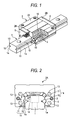
- Fig. 1 shows an external appearance of a linear guide apparatus according to the invention.
- Fig. 2 shows an inner construction of a slider main body of the linear guide apparatus.
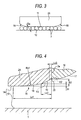
- Fig. 3 is a view as seen in a direction indicated by arrows A in Fig. 2 .
- a linear guide apparatus has a guide rail 1 and a gate-shaped slider 2 which is built on the guide rail 1 so as to move therealong.
- a rolling element raceway groove 10 (rail-side rolling element groove), which is made up of a recess groove extending axially and formed into an arc-like shape of one-fourth of a circle, is formed in each of ridge portions where an upper surface of the guide rail 1 intersects side surfaces 1a thereof.
- a rolling element raceway groove 10, which is made up of a recess groove extending axially and having a substantially semi-circular cross section, is also formed in an intermediate position on each of both the side surfaces 1a of the guide rail 1.
- the slider 2 is made up of a slider main body 2A and gate-shaped end caps 2B which are detachably attached to both axial end portions of the slider main body 2A. Furthermore, a side seal 5 is mounted on an end face of each of the end caps 2B so as to cover an opening formed by a gap between the guide rail 1 and the slider 2 in a sealed fashion. As is shown in Fig. 2 , a rolling element raceway groove (the slider-side rolling element raceway groove) 11 having a semi-circular cross section is formed in a corner portion on an internal side of each of arm portions 6 of the slider main body 2A so as to face the rolling element raceway groove 10 on the guide rail 1.
- a rolling element raceway groove (the slider-side rolling element raceway groove) 11 having a semi-circular cross section is formed in a corner portion on an internal side of each of arm portions 6 of the slider main body 2A so as to face the rolling element raceway groove 10 on the guide rail 1.
- rolling element rolling paths 14 are formed by the rolling element raceway grooves 10 on the guide rail 1 and the rolling element raceway grooves 11 on both the arm portions 6 of the slider main body 2A, and these rolling element rolling paths 14 extend in the axial direction.
- the slider 2 includes rolling element return paths 13 which are made up, respectively, of circular through holes which pass axially through thick portions of the arm portions 6 of the slider main body 2 in upper and lower portions thereof in parallel with the rolling element rolling paths 14, respectively.
- the end cap 2B has direction turning paths which cause the rolling element rolling paths 14 to communicate with the rolling element return paths 13, respectively.
- This direction turning path is made to allow rolling elements 3 to be sent from a terminating point of the rolling element rolling path 14 to an initiating point of the rolling element return path 13 or from a terminating point of the rolling element return path 13 to an initiating point of the rolling element rolling path 14.
- Fig. 3 is a conceptual view taken along the line A-A and seen in the direction indicated by the arrows relative to a direction of a contact angle between the rolling element raceway grooves 10, 11 which make up the rolling element rolling path 14, inclined portions 15 are provided at both end portions of the slider main body 2A.
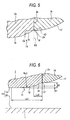
- Figs. 4 and 5 show an inclined portion 15 of a first embodiment according to the invention in an enlarged fashion.
- the inclined portion 15 is actually an extremely minute portion and has dimensions which make it difficult for the inclined portion 15 to be visible to the naked eyes, the inclined portion 15 is shown in an exaggerated fashion for the sake of understandable explanation.
- reference numeral 16 denotes a return guide (the inner circumferential guide member) interposed between the slider main body 2A and the end cap 2B, and an inner circumferential side circulation groove 17, which extends into a semi-circular arc-like shape, is formed on an outer circumference of the return guide 16.
- the inclined portion 15 of this embodiment includes a curved first crowning 18 which continues from the rolling element raceway groove 11, a second crowning 19 (second crowning) which neighbors the first crowning 18 and extends in a straight line towards an end face 2a of the slider main body 2A and a slope 20 which extends in a straight line between the second crowning 19 and the end face 2a of the slider main body 2A.
- the first crowning 18 is formed into a curved line with a large radius of curvature Rc1 so as to be inclined moderately.
- the second crowning 19 is formed so as to be inclined further in a direction in which it moves away from the rolling element raceway groove 10 on the guide rail 1 which it faces than a first imaginary line (a line indicated by a broken line which extends along the first crowning 18 in Fig. 4 ) K1 of the first crowning 18.
- the slope 20 is formed into a straight-line shape which is inclined further in a direction in which it moves away from the rolling element raceway groove 10 on the guide rail 1 which it faces than a second imaginary line (a line indicated by a broken line) K2 (the imaginary line which is extending in a straight line along the second crowning) which extends in a straight line along the second crowning 19.
- a intersection point between a third imaginary line (a line indicated by a broken line) K3 (the linear imaginary line which is extending along the end face of the slider main body) which extends along the end face 2a of the slider main body 2A and the second imaginary line K2 is formed so as to substantially coincide with a intersection point between a fourth imaginary line K4 (the imaginary line which is extending along the outer circumference of the inner circumferential guide member which makes up the inner circumferential surface of the direction turning path) which extends along the inner circumferential side circulation groove 17 of the return guide 16 and the third imaginary line K3 (a position indicated by reference character P in Fig. 5 ).
- the second crowning 19 is provided so as to be substantially level with an inner circumferential surface of the direction turning path which is made up of the inner circumferential side circulation groove 17 of the return guide 16.
- a maximum depth ⁇ 1 of the first crowning 18 is set to be on the order of 0.3% of a diameter Da (refer to Fig. 3 ) of the rolling elements 3 which corresponds to a pre-load amount of the linear guide apparatus of the embodiment, and a maximum depth ⁇ 2 of the second crowning 19 is set to be on the order of 1.5% of the diameter Da of the rolling elements 3.
- a crowning length Lc1 of the first crowning 18 is set to be substantially 1.9 times the diameter Da of the rolling elements 3
- a crowning length Lc2 of the second crowning 19 is set to be substantially 0.5 times the diameter Da of the rolling elements 3.
- the slope 20 is inclined substantially at 45° relative to the rolling element raceway groove 11 of the slider main body 2A, and a length Lc3 thereof is set to be on the order of 0.05 to 0.3 mm.
- the maximum depth ⁇ 1 of the first crowning 18 is made to be in the range of 0.1 to 0.5% of the diameter Da of the rolling elements 3
- the maximum depth ⁇ 2 of the second crowning 19 is made to be in the range of 0.7 to 4.0% of the diameter Da of the rolling elements 3
- the length of the first crowning 18 is in the range of 1.5 to 4.0 times the diameter Da of the rolling elements 3
- the inclination angle of the second crowning 19 is made to be less than 5° relative to the rolling element raceway groove 11 of the slider main body 2A.
- the first crowning 18 is formed into the curved surface shape with the large radius of curvature Rc1 so as to be inclined moderately is formed on each of the inclined portions 15 provided at both the end portions of the slider main body 2A so as to continue from the rolling element raceway groove 11, rolling element passing vibrations are reduced.
- the straight-line second crowning 19 is also provided on each of the inclined portions 15 which neighbors the first crowning 18 and which is inclined steeper than the first crowning 18 and is made shorter in axial length than the first crowning 18, the rolling elements 3 can be made to roll smoothly while suppressing the axial length, when compared to the conventional linear guide apparatus in which the single linear crowning and the single curvilinear crowning are formed on each of the end portions of the slider main body 2A. Therefore, a drastic change in load on the rolling elements 3 which pass through the inclined portions 15 is absorbed so as to suppress the reduction in rigidity and load-carrying capacity.
- the second crowning 19 makes up a colliding surface for the rolling elements 3 which roll towards the inclined portions 15 from the direction turning paths when the linear guide apparatus is driven at high speeds
- the second crowning 19 is not formed into the edge shape or the protruding shape as in the case of the conventional linear guide apparatus but is formed into the straight-line shape, whereby since stress generated in the rolling elements 3 and the second crowning 19 when the former is brought into collision with the latter is reduced, compared to the conventional linear guide apparatus, the durability of the linear guide apparatus when it is driven at high speeds is enhanced.
- the second crowning 19 may be formed into a concave or recess shape.
- the second crowning 19 is formed so as to be substantially level with the inner circumferential surface of the direction turning path (the inner circumferential side circulation groove 17 of the return guide 16) as viewed in the section in the direction in which the inclined portions 15 contact the rolling elements 3, even when the rolling elements 3 are circulated from the direction turning path to the inclined portion 15 side or from the inclined portion 15 side towards the direction turning path, the rolling elements 3 are allowed to roll smoothly.
- the slope 20 is provided between the second crowning 19 and the end face 2a of the slider main body 2A, influences from manufacturing or molding tolerances of components and assembling tolerances of the components can be absorbed by the slope 20, and this reduces the number of manufacturing steps including inspections, thereby making it possible to increase the productivity.
- the difference in level is caused between the end face 2a of the slider main body 2A and the return guide 16
- the amount of difference in level can be reduced to one-half of that of the case where the difference in level is intentionally provided on the end face 2a of the slider main body 2A and one side of the return guide with the same component accuracy and assembling accuracy.
- the inclined portions 15 are each made up of the curved first crowning 18 which is formed to the large radius of curvature Rc1 so as to be inclined moderately and continuously from the slider-side rolling element raceway groove 11, the straight-line second crowning 19 which neighbors the first crowning 18 and extends towards the inner circumferential surface of the direction turning path (the inner circumferential side circulation groove 17 of the return guide 16) and which is steeper in inclination than the first crowning 18 and shorter in axial length than the first crowning 18, and the slope 20 which is provided between the second crowning 19 and the end face 2a of the slider main body 2A and is formed steeper than the first and second crownings 18, 19.
- the intersection point between the imaginary line K1 extending linearly along the second crowning 19 and the linear imaginary line K3 extending along the end face 2a of the slider main body 2A substantially coincides with the intersection point between the imaginary line K4 extending along the inner circumferential side circulation groove 17 of the return guide 16 and the linear imaginary line K3 extending along the end face 2a of the slider main body 2A. Therefore, the linear guide apparatus can be provided which not only enhances the durability thereof when it is driven at high speeds without reducing the productivity but also suppresses the reduction in load-carrying capacity and rigidity without deteriorating the rolling element passing vibrations.
- Fig. 6 shows an inclined portion 15 of a second embodiment according to the invention in an enlarged fashion.
- a round-shaped slope 22 is formed between a second crowning 19 and an end face 2a of a slider main body 2A.
- the rounded slope in the claim corresponds to the rounded-shaped slope 22.
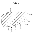
- Fig. 7 shows an inclined portion 15 of a third embodiment according to the invention in an enlarged fashion.
- a rounded portion 23 (a boundary portion between the first crowning and the second crowning being formed so as to be rounded) is formed between a first crowning 18 and a second crowning 19, and a rounded portion 24 (a boundary portion between the second crowning and the slope being formed so as to be rounded) is also formed between the second crowning 19 and a slope 20.
- the rounded portion between the first crowning 18 and the second crowning 19 and the rounded portion 24 between the second crowning 19 and the slope 20 since a location can be eliminated where rolling elements 3 which pass through the inclined portion 15 are brought into collision to produce a stress concentration, the component accuracy and mounting accuracy can be made stable, and the durability of the linear guide apparatus when it is driven at high speeds can be enhanced.
- Figs. 1 and 2 show the construction in which the two rolling element rolling paths 14 are formed between each of the sides of the guide rail 1 and each of the arm portions 6 of the bearing block 2A, the gist of the invention is not limited thereto. Hence, even in the event that one or three or more rolling element rolling paths 14 are formed in the same way, the same function and advantage can be provided.
- the balls are described as being used as the rolling elements 3, even in the event that "rollers" are used as the rolling elements, the same function and advantage can be provided.
Landscapes
- Engineering & Computer Science (AREA)
- General Engineering & Computer Science (AREA)
- Mechanical Engineering (AREA)
- Bearings For Parts Moving Linearly (AREA)
Applications Claiming Priority (1)
| Application Number | Priority Date | Filing Date | Title |
|---|---|---|---|
| JP2006318177A JP4853254B2 (ja) | 2006-11-27 | 2006-11-27 | 直動案内装置 |
Publications (1)
| Publication Number | Publication Date |
|---|---|
| EP1925834A2 true EP1925834A2 (en) | 2008-05-28 |
Family
ID=39166841
Family Applications (1)
| Application Number | Title | Priority Date | Filing Date |
|---|---|---|---|
| EP07022901A Withdrawn EP1925834A2 (en) | 2006-11-27 | 2007-11-26 | Linear guide apparatus |
Country Status (5)
| Country | Link |
|---|---|
| US (1) | US7771119B2 (ja) |
| EP (1) | EP1925834A2 (ja) |
| JP (1) | JP4853254B2 (ja) |
| CN (1) | CN101191516A (ja) |
| TW (1) | TWI333031B (ja) |
Families Citing this family (9)
| Publication number | Priority date | Publication date | Assignee | Title |
|---|---|---|---|---|
| TWI593612B (zh) * | 2014-11-25 | 2017-08-01 | 家登精密工業股份有限公司 | 晶圓盒及其門閂定向裝置 |
| CN105570296A (zh) * | 2016-02-01 | 2016-05-11 | 嘉兴海菱达精密传动科技有限公司 | 一种改进型滚动直线导轨副 |
| JP6651412B2 (ja) * | 2016-05-25 | 2020-02-19 | Thk株式会社 | 転がり案内装置 |
| JP6981746B2 (ja) | 2016-10-26 | 2021-12-17 | 日本トムソン株式会社 | 直動案内ユニット |
| JP6827843B2 (ja) | 2017-02-23 | 2021-02-10 | 日本トムソン株式会社 | 直動案内ユニット |
| KR102061550B1 (ko) * | 2018-03-23 | 2020-01-02 | (주)원에스티 | 직선 운동 안내 장치 |
| WO2019182327A1 (ko) * | 2018-03-23 | 2019-09-26 | (주)원에스티 | 직선 운동 안내 장치 |
| WO2020110754A1 (ja) * | 2018-11-27 | 2020-06-04 | Thk株式会社 | 運動案内装置 |
| KR102647697B1 (ko) * | 2018-12-28 | 2024-03-15 | 주식회사 베어링아트 | 텐덤 볼 베어링 |
Citations (6)
| Publication number | Priority date | Publication date | Assignee | Title |
|---|---|---|---|---|
| JP2002155936A (ja) | 2000-11-17 | 2002-05-31 | Thk Co Ltd | 案内装置 |
| JP2003035314A (ja) | 2001-07-23 | 2003-02-07 | Nsk Ltd | 転がり直動案内装置の設計方法及びこれにより設計された転がり直動案内装置 |
| WO2005019668A1 (ja) | 2003-08-25 | 2005-03-03 | Nsk Ltd. | 直動案内装置 |
| JP2005273765A (ja) | 2004-03-24 | 2005-10-06 | Nippon Thompson Co Ltd | 直動案内ユニット |
| JP2005337455A (ja) | 2004-05-28 | 2005-12-08 | Nsk Ltd | リニアガイド装置 |
| JP2006029384A (ja) | 2004-07-13 | 2006-02-02 | Nsk Ltd | 直動案内装置 |
Family Cites Families (3)
| Publication number | Priority date | Publication date | Assignee | Title |
|---|---|---|---|---|
| JPH0235051Y2 (ja) * | 1985-02-14 | 1990-09-21 | ||
| WO2005108807A1 (ja) | 2004-05-12 | 2005-11-17 | Thk Co., Ltd. | 転がり機械要素 |
| JP2006316886A (ja) * | 2005-05-12 | 2006-11-24 | Nsk Ltd | 直動案内装置 |
-
2006
- 2006-11-27 JP JP2006318177A patent/JP4853254B2/ja active Active
-
2007
- 2007-10-29 US US11/926,195 patent/US7771119B2/en active Active
- 2007-10-31 TW TW096141065A patent/TWI333031B/zh active
- 2007-11-26 CN CNA2007101875617A patent/CN101191516A/zh active Pending
- 2007-11-26 EP EP07022901A patent/EP1925834A2/en not_active Withdrawn
Patent Citations (6)
| Publication number | Priority date | Publication date | Assignee | Title |
|---|---|---|---|---|
| JP2002155936A (ja) | 2000-11-17 | 2002-05-31 | Thk Co Ltd | 案内装置 |
| JP2003035314A (ja) | 2001-07-23 | 2003-02-07 | Nsk Ltd | 転がり直動案内装置の設計方法及びこれにより設計された転がり直動案内装置 |
| WO2005019668A1 (ja) | 2003-08-25 | 2005-03-03 | Nsk Ltd. | 直動案内装置 |
| JP2005273765A (ja) | 2004-03-24 | 2005-10-06 | Nippon Thompson Co Ltd | 直動案内ユニット |
| JP2005337455A (ja) | 2004-05-28 | 2005-12-08 | Nsk Ltd | リニアガイド装置 |
| JP2006029384A (ja) | 2004-07-13 | 2006-02-02 | Nsk Ltd | 直動案内装置 |
Also Published As
| Publication number | Publication date |
|---|---|
| TW200848632A (en) | 2008-12-16 |
| US20080124011A1 (en) | 2008-05-29 |
| US7771119B2 (en) | 2010-08-10 |
| TWI333031B (en) | 2010-11-11 |
| JP4853254B2 (ja) | 2012-01-11 |
| JP2008133837A (ja) | 2008-06-12 |
| CN101191516A (zh) | 2008-06-04 |
Similar Documents
| Publication | Publication Date | Title |
|---|---|---|
| US7771119B2 (en) | Linear guide apparatus | |
| EP2287480B1 (en) | Motion guide device | |
| EP1580447B1 (en) | Linear motion guide unit | |
| JP2001012477A (ja) | 転がり軸受用保持器 | |
| EP2096326B1 (en) | Ball spline device | |
| EP2604875B1 (en) | Linear motion guide device | |
| EP1617089A2 (en) | Linear guide apparatus | |
| WO2013035769A1 (ja) | 運動案内装置 | |
| JP2003247543A (ja) | 直動案内ユニット | |
| US7210849B2 (en) | Sliding apparatus | |
| US20180112708A1 (en) | Linear motion guide unit | |
| WO2003000444A1 (en) | Material for rail of linear guide, rail for linear guide, process of manufacturing rail of linear guide, and linear guide | |
| JP2007120766A (ja) | 転がり軸受用保持器 | |
| KR100348985B1 (ko) | 직선롤러안내장치 | |
| US5649769A (en) | Linear motion rolling guide unit | |
| EP1310689B1 (en) | Linear guide bearing apparatus | |
| US11852192B2 (en) | Motion guide apparatus | |
| JP2015117734A (ja) | 直動案内装置 | |
| JP2005201318A (ja) | ローラチェーン及びそれを組み込んだ案内ユニット | |
| CN114945756A (zh) | 直动引导轴承 | |
| CN117043480A (zh) | 圆锥滚子轴承 | |
| JP2008039041A (ja) | リニアガイド装置 | |
| JP2005155798A (ja) | リニアガイド装置 | |
| JP2006300164A (ja) | リニアガイド装置 |
Legal Events
| Date | Code | Title | Description |
|---|---|---|---|
| PUAI | Public reference made under article 153(3) epc to a published international application that has entered the european phase |
Free format text: ORIGINAL CODE: 0009012 |
|
| AK | Designated contracting states |
Kind code of ref document: A2 Designated state(s): AT BE BG CH CY CZ DE DK EE ES FI FR GB GR HU IE IS IT LI LT LU LV MC MT NL PL PT RO SE SI SK TR |
|
| AX | Request for extension of the european patent |
Extension state: AL BA HR MK RS |
|
| STAA | Information on the status of an ep patent application or granted ep patent |
Free format text: STATUS: THE APPLICATION HAS BEEN WITHDRAWN |
|
| 18W | Application withdrawn |
Effective date: 20090706 |