EP1925802B1 - Moteur à combustion interne HCCI à redémarrage rapide - Google Patents
Moteur à combustion interne HCCI à redémarrage rapide Download PDFInfo
- Publication number
- EP1925802B1 EP1925802B1 EP06124586A EP06124586A EP1925802B1 EP 1925802 B1 EP1925802 B1 EP 1925802B1 EP 06124586 A EP06124586 A EP 06124586A EP 06124586 A EP06124586 A EP 06124586A EP 1925802 B1 EP1925802 B1 EP 1925802B1
- Authority
- EP
- European Patent Office
- Prior art keywords
- fuel
- fuel injection
- combustion
- piston
- control means
- Prior art date
- Legal status (The legal status is an assumption and is not a legal conclusion. Google has not performed a legal analysis and makes no representation as to the accuracy of the status listed.)
- Not-in-force
Links
- 238000002485 combustion reaction Methods 0.000 title claims description 114
- 239000000446 fuel Substances 0.000 claims description 113
- 238000002347 injection Methods 0.000 claims description 57
- 239000007924 injection Substances 0.000 claims description 57
- 230000006835 compression Effects 0.000 claims description 40
- 238000007906 compression Methods 0.000 claims description 40
- 239000007789 gas Substances 0.000 claims description 24
- 238000000034 method Methods 0.000 claims description 22
- QVGXLLKOCUKJST-UHFFFAOYSA-N atomic oxygen Chemical compound [O] QVGXLLKOCUKJST-UHFFFAOYSA-N 0.000 claims description 7
- 230000006698 induction Effects 0.000 claims description 7
- 239000001301 oxygen Substances 0.000 claims description 7
- 229910052760 oxygen Inorganic materials 0.000 claims description 7
- 239000000203 mixture Substances 0.000 description 11
- 238000010586 diagram Methods 0.000 description 6
- 230000001965 increasing effect Effects 0.000 description 4
- 230000007704 transition Effects 0.000 description 3
- 230000000694 effects Effects 0.000 description 2
- 238000010438 heat treatment Methods 0.000 description 2
- 238000005086 pumping Methods 0.000 description 2
- 238000006243 chemical reaction Methods 0.000 description 1
- 230000001419 dependent effect Effects 0.000 description 1
- 238000009792 diffusion process Methods 0.000 description 1
- 239000012895 dilution Substances 0.000 description 1
- 238000010790 dilution Methods 0.000 description 1
- 230000002708 enhancing effect Effects 0.000 description 1
- 230000014509 gene expression Effects 0.000 description 1
- 238000012986 modification Methods 0.000 description 1
- 230000004048 modification Effects 0.000 description 1
- TVMXDCGIABBOFY-UHFFFAOYSA-N octane Chemical compound CCCCCCCC TVMXDCGIABBOFY-UHFFFAOYSA-N 0.000 description 1
- 238000002360 preparation method Methods 0.000 description 1
- 230000001902 propagating effect Effects 0.000 description 1
- 239000000243 solution Substances 0.000 description 1
- 238000006467 substitution reaction Methods 0.000 description 1
- 230000001052 transient effect Effects 0.000 description 1
Images


Classifications
-
- F—MECHANICAL ENGINEERING; LIGHTING; HEATING; WEAPONS; BLASTING
- F02—COMBUSTION ENGINES; HOT-GAS OR COMBUSTION-PRODUCT ENGINE PLANTS
- F02D—CONTROLLING COMBUSTION ENGINES
- F02D41/00—Electrical control of supply of combustible mixture or its constituents
- F02D41/30—Controlling fuel injection
- F02D41/3011—Controlling fuel injection according to or using specific or several modes of combustion
- F02D41/3017—Controlling fuel injection according to or using specific or several modes of combustion characterised by the mode(s) being used
- F02D41/3035—Controlling fuel injection according to or using specific or several modes of combustion characterised by the mode(s) being used a mode being the premixed charge compression-ignition mode
-
- F—MECHANICAL ENGINEERING; LIGHTING; HEATING; WEAPONS; BLASTING
- F02—COMBUSTION ENGINES; HOT-GAS OR COMBUSTION-PRODUCT ENGINE PLANTS
- F02D—CONTROLLING COMBUSTION ENGINES
- F02D13/00—Controlling the engine output power by varying inlet or exhaust valve operating characteristics, e.g. timing
- F02D13/02—Controlling the engine output power by varying inlet or exhaust valve operating characteristics, e.g. timing during engine operation
- F02D13/0261—Controlling the valve overlap
- F02D13/0265—Negative valve overlap for temporarily storing residual gas in the cylinder
-
- F—MECHANICAL ENGINEERING; LIGHTING; HEATING; WEAPONS; BLASTING
- F02—COMBUSTION ENGINES; HOT-GAS OR COMBUSTION-PRODUCT ENGINE PLANTS
- F02D—CONTROLLING COMBUSTION ENGINES
- F02D35/00—Controlling engines, dependent on conditions exterior or interior to engines, not otherwise provided for
- F02D35/02—Controlling engines, dependent on conditions exterior or interior to engines, not otherwise provided for on interior conditions
- F02D35/028—Controlling engines, dependent on conditions exterior or interior to engines, not otherwise provided for on interior conditions by determining the combustion timing or phasing
-
- F—MECHANICAL ENGINEERING; LIGHTING; HEATING; WEAPONS; BLASTING
- F02—COMBUSTION ENGINES; HOT-GAS OR COMBUSTION-PRODUCT ENGINE PLANTS
- F02D—CONTROLLING COMBUSTION ENGINES
- F02D41/00—Electrical control of supply of combustible mixture or its constituents
- F02D41/02—Circuit arrangements for generating control signals
- F02D41/04—Introducing corrections for particular operating conditions
- F02D41/12—Introducing corrections for particular operating conditions for deceleration
- F02D41/123—Introducing corrections for particular operating conditions for deceleration the fuel injection being cut-off
- F02D41/126—Introducing corrections for particular operating conditions for deceleration the fuel injection being cut-off transitional corrections at the end of the cut-off period
-
- F—MECHANICAL ENGINEERING; LIGHTING; HEATING; WEAPONS; BLASTING
- F02—COMBUSTION ENGINES; HOT-GAS OR COMBUSTION-PRODUCT ENGINE PLANTS
- F02B—INTERNAL-COMBUSTION PISTON ENGINES; COMBUSTION ENGINES IN GENERAL
- F02B1/00—Engines characterised by fuel-air mixture compression
- F02B1/12—Engines characterised by fuel-air mixture compression with compression ignition
-
- F—MECHANICAL ENGINEERING; LIGHTING; HEATING; WEAPONS; BLASTING
- F02—COMBUSTION ENGINES; HOT-GAS OR COMBUSTION-PRODUCT ENGINE PLANTS
- F02B—INTERNAL-COMBUSTION PISTON ENGINES; COMBUSTION ENGINES IN GENERAL
- F02B75/00—Other engines
- F02B75/12—Other methods of operation
- F02B2075/125—Direct injection in the combustion chamber for spark ignition engines, i.e. not in pre-combustion chamber
-
- F—MECHANICAL ENGINEERING; LIGHTING; HEATING; WEAPONS; BLASTING
- F02—COMBUSTION ENGINES; HOT-GAS OR COMBUSTION-PRODUCT ENGINE PLANTS
- F02D—CONTROLLING COMBUSTION ENGINES
- F02D13/00—Controlling the engine output power by varying inlet or exhaust valve operating characteristics, e.g. timing
- F02D13/02—Controlling the engine output power by varying inlet or exhaust valve operating characteristics, e.g. timing during engine operation
- F02D13/0203—Variable control of intake and exhaust valves
-
- F—MECHANICAL ENGINEERING; LIGHTING; HEATING; WEAPONS; BLASTING
- F02—COMBUSTION ENGINES; HOT-GAS OR COMBUSTION-PRODUCT ENGINE PLANTS
- F02D—CONTROLLING COMBUSTION ENGINES
- F02D41/00—Electrical control of supply of combustible mixture or its constituents
- F02D41/0002—Controlling intake air
- F02D2041/001—Controlling intake air for engines with variable valve actuation
-
- F—MECHANICAL ENGINEERING; LIGHTING; HEATING; WEAPONS; BLASTING
- F02—COMBUSTION ENGINES; HOT-GAS OR COMBUSTION-PRODUCT ENGINE PLANTS
- F02D—CONTROLLING COMBUSTION ENGINES
- F02D41/00—Electrical control of supply of combustible mixture or its constituents
- F02D41/02—Circuit arrangements for generating control signals
- F02D41/04—Introducing corrections for particular operating conditions
- F02D41/06—Introducing corrections for particular operating conditions for engine starting or warming up
- F02D41/062—Introducing corrections for particular operating conditions for engine starting or warming up for starting
- F02D41/065—Introducing corrections for particular operating conditions for engine starting or warming up for starting at hot start or restart
-
- F—MECHANICAL ENGINEERING; LIGHTING; HEATING; WEAPONS; BLASTING
- F02—COMBUSTION ENGINES; HOT-GAS OR COMBUSTION-PRODUCT ENGINE PLANTS
- F02D—CONTROLLING COMBUSTION ENGINES
- F02D41/00—Electrical control of supply of combustible mixture or its constituents
- F02D41/02—Circuit arrangements for generating control signals
- F02D41/04—Introducing corrections for particular operating conditions
- F02D41/12—Introducing corrections for particular operating conditions for deceleration
- F02D41/123—Introducing corrections for particular operating conditions for deceleration the fuel injection being cut-off
-
- F—MECHANICAL ENGINEERING; LIGHTING; HEATING; WEAPONS; BLASTING
- F02—COMBUSTION ENGINES; HOT-GAS OR COMBUSTION-PRODUCT ENGINE PLANTS
- F02D—CONTROLLING COMBUSTION ENGINES
- F02D41/00—Electrical control of supply of combustible mixture or its constituents
- F02D41/30—Controlling fuel injection
- F02D41/3011—Controlling fuel injection according to or using specific or several modes of combustion
- F02D41/3017—Controlling fuel injection according to or using specific or several modes of combustion characterised by the mode(s) being used
- F02D41/3023—Controlling fuel injection according to or using specific or several modes of combustion characterised by the mode(s) being used a mode being the stratified charge spark-ignited mode
-
- F—MECHANICAL ENGINEERING; LIGHTING; HEATING; WEAPONS; BLASTING
- F02—COMBUSTION ENGINES; HOT-GAS OR COMBUSTION-PRODUCT ENGINE PLANTS
- F02D—CONTROLLING COMBUSTION ENGINES
- F02D41/00—Electrical control of supply of combustible mixture or its constituents
- F02D41/30—Controlling fuel injection
- F02D41/3011—Controlling fuel injection according to or using specific or several modes of combustion
- F02D41/3017—Controlling fuel injection according to or using specific or several modes of combustion characterised by the mode(s) being used
- F02D41/3035—Controlling fuel injection according to or using specific or several modes of combustion characterised by the mode(s) being used a mode being the premixed charge compression-ignition mode
- F02D41/3041—Controlling fuel injection according to or using specific or several modes of combustion characterised by the mode(s) being used a mode being the premixed charge compression-ignition mode with means for triggering compression ignition, e.g. spark plug
-
- F—MECHANICAL ENGINEERING; LIGHTING; HEATING; WEAPONS; BLASTING
- F02—COMBUSTION ENGINES; HOT-GAS OR COMBUSTION-PRODUCT ENGINE PLANTS
- F02D—CONTROLLING COMBUSTION ENGINES
- F02D41/00—Electrical control of supply of combustible mixture or its constituents
- F02D41/30—Controlling fuel injection
- F02D41/38—Controlling fuel injection of the high pressure type
- F02D41/40—Controlling fuel injection of the high pressure type with means for controlling injection timing or duration
- F02D41/402—Multiple injections
-
- F—MECHANICAL ENGINEERING; LIGHTING; HEATING; WEAPONS; BLASTING
- F02—COMBUSTION ENGINES; HOT-GAS OR COMBUSTION-PRODUCT ENGINE PLANTS
- F02M—SUPPLYING COMBUSTION ENGINES IN GENERAL WITH COMBUSTIBLE MIXTURES OR CONSTITUENTS THEREOF
- F02M26/00—Engine-pertinent apparatus for adding exhaust gases to combustion-air, main fuel or fuel-air mixture, e.g. by exhaust gas recirculation [EGR] systems
- F02M26/01—Internal exhaust gas recirculation, i.e. wherein the residual exhaust gases are trapped in the cylinder or pushed back from the intake or the exhaust manifold into the combustion chamber without the use of additional passages
-
- Y—GENERAL TAGGING OF NEW TECHNOLOGICAL DEVELOPMENTS; GENERAL TAGGING OF CROSS-SECTIONAL TECHNOLOGIES SPANNING OVER SEVERAL SECTIONS OF THE IPC; TECHNICAL SUBJECTS COVERED BY FORMER USPC CROSS-REFERENCE ART COLLECTIONS [XRACs] AND DIGESTS
- Y02—TECHNOLOGIES OR APPLICATIONS FOR MITIGATION OR ADAPTATION AGAINST CLIMATE CHANGE
- Y02T—CLIMATE CHANGE MITIGATION TECHNOLOGIES RELATED TO TRANSPORTATION
- Y02T10/00—Road transport of goods or passengers
- Y02T10/10—Internal combustion engine [ICE] based vehicles
- Y02T10/12—Improving ICE efficiencies
Definitions
- the present invention relates to an internal combustion engine for motor vehicles.
- the engine can be operated in homogeneous charge compression ignition (HCCI) combustion mode and in conventional spark ignited (SI) combustion mode.
- HCCI homogeneous charge compression ignition
- SI spark ignited
- the present invention further relates to a method for controlling such an engine as well as an automotive vehicle comprising such an engine.
- lean burn In order to improve thermal efficiency of gasoline internal combustion engines, lean burn is known to give enhanced thermal efficiency by reducing pumping losses and increasing ratio of specific heats. Generally speaking, lean burn is known to give low fuel consumption and low NO X emissions. There is however a limit at which an engine can be operated with a lean air/fuel mixture because of misfire and combustion instability as a result of a slow burn.
- Known methods to extend the lean limit include improving ignitability of the mixture by enhancing the fuel preparation, for example using atomised fuel or vaporised fuel, and increasing the flame speed by introducing charge motion and turbulence in the air/fuel mixture.
- combustion by auto-ignition, or homogeneous charge compression ignition has been proposed for operating an engine with very lean or diluted air/fuel mixtures.
- homogeneous charge compression ignition can occur wherein bulk combustion takes place initiated simultaneously from many ignition sites within the charge, resulting in very stable power output, very clean combustion and high fuel conversion efficiency.
- NO X emission produced in controlled homogeneous charge compression ignition combustion is extremely low in comparison with spark ignition combustion based on propagating flame front and heterogeneous charge compression ignition combustion based on an attached diffusion flame.
- the burnt gas temperature is highly heterogeneous within the charge with very high local temperature values creating high NO X emission.
- controlled homogeneous charge compression ignition combustion where the combustion is uniformly distributed throughout the charge from many ignition sites, the burnt gas temperature is substantially homogeneous with much lower local temperature values resulting in very low NO x emission.
- Homogeneous charge compression ignition combustion of a gasoline like fuel requires a temperature of approximately 1100 K to achieve auto ignition. While it may be possible to operate in the HCCI mode over a significantly wide operating range of engine speeds and load, starting in the HCCI mode is considerably more difficult due to cold engine parts causing large heat transfer losses from the charge, and the absence of heat sources.
- a mode switch to normal spark ignition combustion will have to take place following every fuel cut-off, since no exhaust gas from a previous combustion will be available once the engine is to be restarted.
- US 6 336 436 discloses a gasoline engine having an actuating system including an in-cylinder fuel injection system and an ignition system, capable of changing over combustion between spark ignition combustion and compression auto ignition combustion, and a controlling system for controlling the combustion changeover.
- the actuating system is controlled to perform transient combustion such as stratified charge combustion with fuel injection on the compression stroke, or combustion with fuel injection during a valve shutoff period during which intake and exhaust valves are both closed.
- US 6 336 436 deals with the transition between normal spark ignition combustion and compression auto ignition combustion and vice versa, it relies on stratified combustion as an intermediate mode to be able to move actuators, such as the throttle, to a desired setting without causing misfire. However, US 6 336 436 is silent regarding the transition from no combustion to compression auto ignition combustion.
- WO 2006 0 964 29 discloses an apparatus and method of an internal combustion engine as disclosed in the preamble of claim 1.
- An object of the present invention is to provide an improved internal combustion engine operable in homogeneous charge compression ignition (HCCI) combustion mode and in conventional spark ignited combustion mode with HCCI restart capability following fuel cut-off without relying on start-up using a mode switch to normal spark ignition combustion.
- HCCI homogeneous charge compression ignition
- the engine provided with at least one cylinder and comprising: fuel injecting means, for injecting fuel into a combustion chamber, of each cylinder; fuel injection control means, for controlling fuel injection quantity per combustion cycle injected using each said fuel injecting means; a piston , arranged for reciprocating action within the cylinder; at least one intake valve for admitting oxygen containing gas into the cylinder; at least one exhaust valve for exhausting combusted gases from the cylinder; ignition control means, for controlling spark ignited combustion; at least one spark plug arranged to selectively produce a spark within the combustion chamber under control of the ignition control means.
- this object is achieved in accordance with the features of claim 1, which specifies that for restart of homogeneous charge compression ignition combustion operation after one or more cycles without combustion, the engine is arranged to be cranked; and the exhaust valve is arranged to be closed before top dead center during an exhaust stroke of the piston; and the intake valve is arranged to be opened after top dead center during an induction stroke of the piston, and the fuel injection control means are arranged to perform a first fuel injection after closing of the exhaust valve and before top dead center of the piston exhaust stroke; the ignition control means are arranged to cause the spark plug to ignite the first injected quantity of fuel before the opening of the intake valve; the fuel injection control means are arranged to perform at least one further fuel injection in the interval after top dead center of the piston exhaust stroke and before top dead center of a subsequent piston compression stroke.
- a further object of the present invention is to provide a method for restart of homogeneous charge compression ignition combustion after one or more cycles without combustion for an internal combustion engine operable in homogeneous charge compression ignition combustion mode and in conventional spark ignited combustion mode.
- the engine is provided with at least one cylinder and comprising: fuel injecting means, for injecting fuel into a combustion chamber, of each cylinder; fuel injection control means, for controlling fuel injection quantity per combustion cycle injected using each said fuel injecting means; a piston, arranged for reciprocating action within the cylinder; at least one intake valve for admitting oxygen containing gas into the cylinder; at least one exhaust valve for exhausting combusted gases from the cylinder; ignition control means , for controlling spark ignited combustion; at least one spark plug arranged to selectively produce a spark within the combustion chamber under control of the ignition control means.
- this object is achieved in accordance with the features of claim 6, which specifies that the method comprises the steps of, cranking the engine; and closing the exhaust valve before top dead center during an exhaust stroke of the piston; and opening the intake valve after top dead center during an induction stroke of the piston, and performing by means of the fuel injection control means a first fuel injection after closing of the exhaust valve and before top dead center of the piston exhaust stroke; igniting by the ignition control means causing the spark plug to ignite the first injected quantity of fuel before the opening of the intake valve; performing by means of the fuel injection control means at least one further fuel injection in the interval after top dead center of the piston exhaust stroke and before top dead center of a subsequent piston compression stroke.
- the invention concerns an internal combustion engine operable in homogeneous charge compression ignition (HCCI) combustion mode and in conventional spark ignited (SI) combustion mode.
- HCCI homogeneous charge compression ignition
- SI spark ignited
- the engine is possible to be operated in homogeneous charge compression ignition (HCCI) combustion mode.
- HCCI charge compression ignition
- SI spark ignited
- a mixture containing fuel, air and combustion residuals is compressed to auto ignition.
- HCCI combustion is characterized by many exothermal centers and the energy is released in a higher rate compared to combustion with a moving flame front originating from the sparkplug (SI).
- SI sparkplug
- the stoichiometric mixture In order to slow down the heat-release rate the stoichiometric mixture must be diluted with either air (enleanment) or residuals.
- the dilution rate can be higher compared to an SI engine due to the lack of a moving flame-front.
- the increased mass reduces the maximum temperature hence increases the thermal efficiency. This reduces both pumping losses and combustion temperature hence the fuel consumption compared to an SI operated engine.
- FIG. 1 shows a schematic illustration of an internal combustion engine according to the invention.
- the engine is provided with at least one cylinder 1 and comprises fuel injecting means, such as a fuel injector 2, through which fuel is injected into a combustion chamber 3, of each cylinder 1.
- Fuel injection control means such as a fuel injection control unit 4 controls fuel injection quantity per combustion cycle injected through each fuel injector 2.
- a piston 5 arranged for reciprocating action within in the engine cylinder 1 has a compression action that during HCCI-mode causes a mixture of air and fuel within the combustion chamber 3 to self ignite.
- the cylinder 1 is provided with at least one intake valve 6 for admitting oxygen containing gas, such as fresh air, into the cylinder 1 and at least one exhaust valve 7 for exhausting combusted gases from the cylinder 1.
- Means 11, 12 are provided for controlling timing, duration and lift of the intake valve 6 and the outlet valve 7 respectively.
- Air is supplied through an intake conduit 9 connected to an intake manifold (not shown), while exhaust gas is exhausted through an exhaust conduit 10 connected to an exhaust system (not shown).
- a spark plug 8 When operated in SI-mode, the fuel/air mixture is ignited by a spark plug 8, which is arranged to selectively produce a spark within the combustion chamber 3 under control of ignition control means, which may be integral to an engine control unit (ECU) 4.
- ECU engine control unit
- Gas exchange within the engine is as described above controlled by at least one intake valve 6 preferably, but not necessarily, provided with variable valve timing per cylinder for admitting a combustible oxygen containing gas, such as fresh air, and at least one exhaust valve 7 preferably, but not necessarily, provided with variable valve timing per cylinder for exhausting combusted gases.
- a combustible oxygen containing gas such as fresh air
- an exhaust valve 7 preferably, but not necessarily, provided with variable valve timing per cylinder for exhausting combusted gases.
- the engine is arranged to be cranked and the exhaust valve 7 is arranged to be closed before top dead centre during an exhaust stroke of the piston 5 and the intake valve 6 is arranged to be opened after top dead centre during an induction stroke of the piston 5.
- the fuel injection control means 4 are arranged to perform a first fuel injection after closing of the exhaust valve 7 and before top dead center of the piston exhaust stroke.
- the ignition control means 4 are arranged to cause the spark plug 8 to ignite the first injected quantity of fuel before the opening of the intake valve 6, thus performing a first combustion during the negative valve overlap whereby hot exhaust gases are confined during the negative valve overlap, and used for heating the intake air and provide a combustion residual content, so that it is possible to initiate non-sparking HCCI operation in the subsequent piston compression stroke.
- the fuel injection control means 4 are thus arranged to perform at least one further fuel injection in the interval after the top dead center of the piston exhaust stroke and before top dead center of the subsequent piston compression stroke mentioned above, which further fuel injection is used for HCCI mode operation.
- Combustion residuals are thus created when operating the engine with a negative valve overlap.
- the residuals thus created increases the temperature of the mixture of intake air and the further fuel injected so that the auto ignition temperature is reached before piston top dead center of the subsequent piston compression stroke.
- the negative valve overlap is thus achieved when the exhaust valve 7 is closed before top dead centre during an exhaust stroke of the piston 5 and the intake valve 6 is opened after top dead centre during an induction stroke of the piston 5 in the gas exchange phase of the combustion.
- valve timing for the negative overlap can be achieved by using suitable fully or partially variable valve systems, variable valve timing (VVT), and cam profile switching (CPS), hence switching from conventional SI valve timing to HCCI valve timing with a shorter valve opening duration and/or valve lift.
- VVT variable valve timing
- CPS cam profile switching
- the means 11, 12 are responsible for controlling timing, duration and lift of the intake valve 6 and the outlet valve 7 respectively.
- the fuel injecting means are arranged to perform the first fuel injection as a stratified stoichiometric charge.
- SI is particularly attractive in its ability to generate heat quickly. Since the ability to operate in the HCCI mode is strongly related to the temperature of the combustion walls (through the effects of heat transfer on charge temperature), the faster the engine can be warmed up, the faster operation can be successfully transitioned to the HCCI mode.
- the present invention further relates to an automotive vehicle comprising an internal combustion engine according to any one of the above described embodiments.
- the present invention also relates to a method for restart of homogeneous charge compression ignition combustion after one or more cycles without combustion for an internal combustion engine operable in homogeneous charge compression ignition combustion mode and in conventional spark ignited combustion mode, where the engine is provided with at least one cylinder 1 and comprises: fuel injecting means 2, for injecting fuel into a combustion chamber 3, of each cylinder 1; fuel injection control means 4, for controlling fuel injection quantity per combustion cycle injected using each said fuel injecting means 2; a piston 5, arranged for reciprocating action within the cylinder 1; at least one intake valve 6 for admitting oxygen containing gas into the cylinder 1; at least one exhaust valve 7 for exhausting combusted gases from the cylinder 1; ignition control means 4, for controlling spark ignited combustion; at least one spark plug 8 arranged to selectively produce a spark within the combustion chamber 3 under control of the ignition control means 4.
- the method in accordance with the present invention comprises the steps of: cranking the engine; and closing the exhaust valve 7 before top dead center during an exhaust stroke of the piston 5; and opening the intake valve 6 after top dead center during an induction stroke of the piston 5, and performing by means of the fuel injection control means 4 a first fuel injection after closing of the exhaust valve 7 and before top dead center of the piston exhaust stroke; igniting by the ignition control means 4 causing the spark plug 8 to ignite the first injected quantity of fuel before the opening of the intake valve 6; performing by means of the fuel injection control means 4 at least one further fuel injection in the interval after top dead center of the piston exhaust stroke and before top dead center of a subsequent piston compression stroke.
- the first fuel injection is performed as a stratified stoichiometric charge using the fuel injecting means 2.
- the at least one further fuel injection is performed as a homogeneous charge using the fuel injecting means 2.
- Figure 2 exemplifies cylinder pressure against crank angle degree during HCCI operation of the internal combustion engine according to figure 1 .
- Area 13 illustrates an example crank angle interval during which the exhaust valve is open.
- Area 14 illustrates the negative valve overlap, and area 15 illustrates an example crank angle interval during which the intake valve is open. It should be noted that the intervals illustrated in figure 2 are provided only as an example and that valve timing is arbitrary.
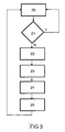
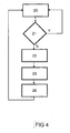
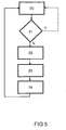
- FIGS 3 , 4 and 5 illustrate flow charts of restart strategies in accordance with the present invention.
- the methods for restart starts with start block 20.
- step 21 is decided if there is combustion or not during a crank angle interval of -180 - 180 degrees in the diagram of figure 2 . If decided that there is combustion the method loops back to start block 20, and if decided in step 21 that there is no combustion a first fuel injection is performed such that the end of said first fuel injection occurs within the crank angle interval of 180 - 360 degrees in the diagram of figure 2 .
- the ignition control means 4 are arranged to cause the spark plug 8 to ignite said first injected quantity of fuel during the crank angle interval of 180 - 360 degrees in the diagram of figure 2 .
- the above steps are common for the different restart strategies of figures 3 , 4 and 5 .
- step 23 is followed by a stratified fuel injection in the crank angle interval of -180 - 180 degrees in the diagram of figure 2 , followed by an ignition spark in step 25, e.g. through the ignition control means 4 being arranged to cause the spark plug 8 to ignite the further injected quantity of fuel in the interval after closing of the intake valve 6 and before top dead centre of a subsequent piston compression stroke, where after the method loops back to start block 20 and is repeated.
- step 23 is followed by fuel injection in the crank angle interval of 360 - 540 degrees in the diagram of figure 2 , where after the method loops back to start block 20 and is repeated.
- step 23 is followed by fuel injection in the crank angle interval of -180 - 180 degrees in the diagram of figure 2 , where after the method loops back to start block 20 and is repeated.
Landscapes
- Engineering & Computer Science (AREA)
- Chemical & Material Sciences (AREA)
- Combustion & Propulsion (AREA)
- Mechanical Engineering (AREA)
- General Engineering & Computer Science (AREA)
- Electrical Control Of Air Or Fuel Supplied To Internal-Combustion Engine (AREA)
Claims (9)
- Moteur à combustion interne utilisable en mode de combustion à autoallumage par compression et en mode de combustion à allumage par étincelle conventionnel, équipé d'au moins un cylindre (1) et comprenant :pour chaque cylindre, des moyens (2) injecteurs de carburant, destinés injecter du carburant dans une chambre de combustion (3) ;des moyens (4) de commande de l'injection du carburant, destinés à commander la quantité d'injection du carburant par cycle de combustion, injectée en utilisant chacun desdits moyens (2) d'injection du carburant ;un piston (5) prévu pour un mouvement alternatif dans ledit cylindre (1) ;au moins une soupape d'admission (6) pour l'admission dans ledit cylindre (1) d'un gaz contenant de l'oxygène ;au moins une soupape d'échappement (7) pour l'échappement des gaz brûlés hors dudit cylindre (1) ;des moyens (4) de commande de l'allumage, pour commander la combustion à allumage par étincelle ;au moins une bougie (8) d'allumage prévue pour produire sélectivement une étincelle dans ladite chambre de combustion (3) sous la commande desdits moyens (4) de commande de l'allumage ; et
caractérisé en ce que, pour le redémarrage d'une opération de combustion à autoallumage par compression après un ou plusieurs cycles sans combustion,
ledit moteur est prévu pour être démarré ; etladite soupape d'échappement (7) est prévue pour être fermée avant le point mort haut pendant une course d'échappement dudit piston (5) ; etladite soupape d'admission (6) est prévue pour être ouverte après le point mort haut pendant une course d'admission dudit piston (5), etlesdits moyens (4) de commande de l'injection du carburant sont prévus pour effectuer une première injection de carburant de telle sorte que la fin de ladite première injection de carburant se produise après la fermeture de ladite soupape d'échappement (7) et avant le point mort haut de ladite course d'échappement du piston ;lesdits moyens (4) de commande de l'allumage sont prévus pour faire que ladite bougie d'allumage (8) provoque l'allumage de ladite première quantité injectée de carburant avant l'ouverture de ladite soupape d'admission (6) ;lesdits moyens (4) de commande de l'injection du carburant sont prévus pour effectuer au moins une autre injection de carburant dans l'intervalle situé après le point mort haut de ladite course d'échappement du piston et avant le point mort haut d'une course de compression du piston qui suivra. - Moteur à combustion interne selon la revendication 1, caractérisé en ce que lesdits moyens (2) injecteurs de carburant sont prévus pour réaliser ladite première injection de carburant sous forme de charge stoechiométrique stratifiée.
- Moteur à combustion interne selon l'une quelconque des revendications 1 à 2, caractérisé en ce que lesdits moyens (2) injecteurs de carburant sont prévus pour réaliser ladite au moins une autre injection de carburant soit sous forme de charge homogène, soit sous forme de charge stratifiée.
- Moteur à combustion interne selon l'une quelconque des revendications 1 à 3, caractérisé en ce que lesdits moyens (4) de commande de l'allumage sont prévus pour faire que ladite bougie d'allumage (8) provoque l'allumage de ladite autre quantité injectée de carburant dans l'intervalle situé après la fermeture de ladite soupape d'admission (6) et avant le point mort haut d'une course de compression du piston qui suivra.
- Véhicule automobile caractérisé en ce qu'il comprend un moteur à combustion interne selon l'une quelconque des revendications précédentes.
- Procédé de redémarrage d'une combustion à autoallumage par compression après un ou plusieurs cycles sans combustion pour un moteur à combustion interne utilisable en mode de combustion à autoallumage par compression et en mode de combustion à allumage par étincelle conventionnel, équipé d'au moins un cylindre (1) et comprenant :pour chaque cylindre (1), des moyens (2) injecteurs de carburant, destinés à injecter du carburant dans une chambre de combustion (3) ;des moyens (4) de commande de l'injection du carburant, destinés à commander la quantité d'injection du carburant par cycle de combustion, injectée en utilisant chacun desdits moyens (2) d'injection du carburant ;un piston (5) prévu pour un mouvement alternatif dans ledit cylindre (1) ;au moins une soupape d'admission (6) pour l'admission dans ledit cylindre (1) d'un gaz contenant de l'oxygène ;au moins une soupape d'échappement (7) pour l'échappement des gaz brûlés hors dudit cylindre (1) ;des moyens (4) de commande de l'allumage, pour commander la combustion à allumage par étincelle ;au moins une bougie (8) d'allumage prévue pour produire sélectivement une étincelle dans ladite chambre de combustion (3) sous la commande desdits moyens (4) de commande de l'allumage ; etcaractérisé en ce que le procédé comprend les étapes consistant à :démarrer ledit moteur ; etfermer ladite soupape d'échappement (7) avant le point mort haut pendant une course d'échappement dudit piston (5) ; etouvrir ladite soupape d'admission (6) après le point mort haut pendant une course d'admission dudit piston (5), eteffectuer, au moyen desdits moyens (4) de commande de l'injection du carburant, une première injection de carburant de telle sorte que la fin de ladite première injection de carburant se produise après la fermeture de ladite soupape d'échappement (7) et avant le point mort haut de ladite course d'échappement du piston ;allumer, avec lesdits moyens (4) de commande de l'allumage faisant que ladite bougie d'allumage (8) provoque l'allumage de ladite première quantité injectée de carburant avant l'ouverture de ladite soupape d'admission (6) ;effectuer, au moyen desdits moyens (4) de commande de l'injection du carburant, au moins une autre injection de carburant dans l'intervalle situé après le point mort haut de ladite course d'échappement du piston et avant le point mort haut d'une course de compression du piston qui suivra.
- Procédé selon la revendication 6, caractérisé en ce que ladite première injection de carburant est effectuée sous forme de charge stoechiométrique stratifiée en utilisant lesdits moyens (2) injecteurs de carburant.
- Procédé selon la revendication 6, caractérisé en ce que ladite au moins une autre injection de carburant est effectuée soit sous forme de charge homogène, soit sous forme de charge stratifiée en utilisant lesdits moyens (2) injecteurs de carburant.
- Procédé selon l'une quelconque des revendications 6 à 8, caractérisé en ce que ladite bougie d'allumage (8) est amenée à provoquer l'allumage de ladite autre quantité injectée de carburant dans l'intervalle situé après la fermeture de ladite soupape d'admission (6) et avant le point mort haut d'une course de compression du piston qui suivra.
Priority Applications (3)
| Application Number | Priority Date | Filing Date | Title |
|---|---|---|---|
| DE602006011483T DE602006011483D1 (de) | 2006-11-22 | 2006-11-22 | HCCI-Brennkraftmaschine mit Schnellneustart |
| EP06124586A EP1925802B1 (fr) | 2006-11-22 | 2006-11-22 | Moteur à combustion interne HCCI à redémarrage rapide |
| US11/925,643 US7810463B2 (en) | 2006-11-22 | 2007-10-26 | Quick restart HCCI internal combustion engine |
Applications Claiming Priority (1)
| Application Number | Priority Date | Filing Date | Title |
|---|---|---|---|
| EP06124586A EP1925802B1 (fr) | 2006-11-22 | 2006-11-22 | Moteur à combustion interne HCCI à redémarrage rapide |
Publications (2)
| Publication Number | Publication Date |
|---|---|
| EP1925802A1 EP1925802A1 (fr) | 2008-05-28 |
| EP1925802B1 true EP1925802B1 (fr) | 2009-12-30 |
Family
ID=37918591
Family Applications (1)
| Application Number | Title | Priority Date | Filing Date |
|---|---|---|---|
| EP06124586A Not-in-force EP1925802B1 (fr) | 2006-11-22 | 2006-11-22 | Moteur à combustion interne HCCI à redémarrage rapide |
Country Status (3)
| Country | Link |
|---|---|
| US (1) | US7810463B2 (fr) |
| EP (1) | EP1925802B1 (fr) |
| DE (1) | DE602006011483D1 (fr) |
Families Citing this family (14)
| Publication number | Priority date | Publication date | Assignee | Title |
|---|---|---|---|---|
| EP1835159B1 (fr) * | 2006-03-15 | 2018-12-19 | Ford Global Technologies, LLC | Procédé pour un moteur à combustion interne, et un moteur à combustion interne |
| JP4743169B2 (ja) * | 2007-06-13 | 2011-08-10 | トヨタ自動車株式会社 | 内燃機関制御装置及び方法 |
| JP4893718B2 (ja) * | 2007-10-03 | 2012-03-07 | マツダ株式会社 | 内燃機関の制御方法および内燃機関の制御装置 |
| DE102007057290B3 (de) * | 2007-11-28 | 2009-04-02 | Continental Automotive Gmbh | Verfahren zum direkten Wiedereintreten in den CAI-Betriebsmodus eines Verbrennungsmotors im Anschluss an eine Schubabschaltphase sowie zugehöriges Steuergerät |
| EP2072786B1 (fr) * | 2007-12-20 | 2013-10-23 | Ford Global Technologies, LLC | Contrôle de cascade de mise en phase HCCI |
| US7565892B1 (en) * | 2008-02-01 | 2009-07-28 | Gm Global Technology Operations, Inc. | Method and apparatus for controlling mode transition in a spark-ignition direct-injection internal combustion engine |
| FR2933449B1 (fr) * | 2008-07-03 | 2010-07-30 | Inst Francais Du Petrole | Procede pour ameliorer la vaporisation d'un carburant utlise pour un moteur a combustion interne, notamment a injection directe, en particulier a autoallumage et plus particulierement de type diesel |
| KR101189229B1 (ko) | 2009-11-12 | 2012-10-09 | 현대자동차주식회사 | 압축 착화 가솔린 엔진 |
| US8539932B2 (en) * | 2009-12-03 | 2013-09-24 | GM Global Technology Operations LLC | Systems and methods for heating intake air during cold HCCI operation |
| US9303577B2 (en) * | 2012-12-19 | 2016-04-05 | Ford Global Technologies, Llc | Method and system for engine cold start and hot start control |
| US9297329B2 (en) * | 2013-04-01 | 2016-03-29 | Ford Global Technologies, Llc | Method and system for engine control |
| JP6268864B2 (ja) * | 2013-09-25 | 2018-01-31 | マツダ株式会社 | 圧縮着火式エンジンの制御装置 |
| JP2020041481A (ja) * | 2018-09-11 | 2020-03-19 | 川崎重工業株式会社 | 発電システム及びそれを備える推進装置 |
| CN116291851B (zh) * | 2023-02-13 | 2023-10-20 | 合肥工业大学 | 一种均质压燃着火装置及其方法 |
Family Cites Families (8)
| Publication number | Priority date | Publication date | Assignee | Title |
|---|---|---|---|---|
| DE19742969C2 (de) * | 1997-09-29 | 2002-08-14 | Siemens Ag | Verfahren zum Starten einer Mehrzylinderbrennkraftmaschine |
| JP4253426B2 (ja) * | 1999-09-14 | 2009-04-15 | 日産自動車株式会社 | 圧縮自己着火式ガソリン機関 |
| DE10020104A1 (de) * | 2000-04-22 | 2001-10-31 | Bosch Gmbh Robert | Verfahren zum Starten einer mehrzylindrigen Brennkraftmaschine |
| DE10245790A1 (de) * | 2002-10-01 | 2004-04-15 | Daimlerchrysler Ag | Brennkraftmaschine mit Selbstzündung |
| DE10260748A1 (de) * | 2002-12-23 | 2004-07-01 | Robert Bosch Gmbh | Verfahren zum Betreiben einer Brennkraftmaschine |
| JP4159918B2 (ja) * | 2003-04-16 | 2008-10-01 | 本田技研工業株式会社 | 圧縮着火式内燃機関の燃料カット制御装置 |
| US7370633B2 (en) * | 2005-03-03 | 2008-05-13 | Gm Global Technology Operations, Inc. | Load transient control methods for direct-injection engines with controlled auto-ignition combustion |
| US7278388B2 (en) * | 2005-05-12 | 2007-10-09 | Ford Global Technologies, Llc | Engine starting for engine having adjustable valve operation |
-
2006
- 2006-11-22 EP EP06124586A patent/EP1925802B1/fr not_active Not-in-force
- 2006-11-22 DE DE602006011483T patent/DE602006011483D1/de active Active
-
2007
- 2007-10-26 US US11/925,643 patent/US7810463B2/en not_active Expired - Fee Related
Also Published As
| Publication number | Publication date |
|---|---|
| US7810463B2 (en) | 2010-10-12 |
| DE602006011483D1 (de) | 2010-02-11 |
| EP1925802A1 (fr) | 2008-05-28 |
| US20080173277A1 (en) | 2008-07-24 |
Similar Documents
| Publication | Publication Date | Title |
|---|---|---|
| US7810463B2 (en) | Quick restart HCCI internal combustion engine | |
| US6516774B2 (en) | Premixed charge compression ignition engine with variable speed SOC control and method of operation | |
| US6443108B1 (en) | Multiple-stroke, spark-ignited engine | |
| US7059281B2 (en) | Four stroke engine auto-ignition combustion | |
| US20040182359A1 (en) | Individual cylinder-switching in a multi-cylinder engine | |
| JPH10252513A (ja) | 4行程機関における自己点火を制御するための方法 | |
| WO2006017084A2 (fr) | Procede de regulation de la combustion a auto-allumage | |
| RU2541346C2 (ru) | Способ эксплуатации двигателя внутреннего сгорания | |
| WO2007125735A1 (fr) | Moteur a allumage par compression a premelange et procede de controle d'admission d'air dans ledit moteur | |
| JP3629879B2 (ja) | 圧縮点火式内燃機関 | |
| JP2012255366A (ja) | 内燃機関の制御装置及び制御方法 | |
| US7712440B2 (en) | Increased HCCI operation window | |
| JP4180995B2 (ja) | 圧縮着火内燃機関の制御装置 | |
| JP2006258078A (ja) | エンジンの制御装置 | |
| US11506168B2 (en) | Gasoline internal combustion engine with assisted compression ignition | |
| JP4274063B2 (ja) | 内燃機関の制御装置 | |
| JP4102268B2 (ja) | 圧縮着火内燃機関 | |
| JP5445421B2 (ja) | 予混合圧縮自己着火エンジン | |
| JP2005061325A (ja) | 圧縮着火内燃機関の制御装置 | |
| WO2012137055A1 (fr) | Dispositif et procédé de commande de démarrage d'un moteur à combustion interne | |
| JP5429148B2 (ja) | 予混合圧縮自己着火エンジン | |
| JP4801744B2 (ja) | 内燃機関の運転方法および装置 | |
| KR100783925B1 (ko) | 차량 엔진의 cai 전환 제어 방법 | |
| JP2000220484A (ja) | 予混合圧縮自着火エンジンとその起動方法 | |
| JP2005325782A (ja) | 内燃機関の燃料噴射制御装置 |
Legal Events
| Date | Code | Title | Description |
|---|---|---|---|
| PUAI | Public reference made under article 153(3) epc to a published international application that has entered the european phase |
Free format text: ORIGINAL CODE: 0009012 |
|
| AK | Designated contracting states |
Kind code of ref document: A1 Designated state(s): AT BE BG CH CY CZ DE DK EE ES FI FR GB GR HU IE IS IT LI LT LU LV MC NL PL PT RO SE SI SK TR |
|
| AX | Request for extension of the european patent |
Extension state: AL BA HR MK RS |
|
| 17P | Request for examination filed |
Effective date: 20080530 |
|
| AKX | Designation fees paid |
Designated state(s): DE GB SE |
|
| GRAP | Despatch of communication of intention to grant a patent |
Free format text: ORIGINAL CODE: EPIDOSNIGR1 |
|
| GRAJ | Information related to disapproval of communication of intention to grant by the applicant or resumption of examination proceedings by the epo deleted |
Free format text: ORIGINAL CODE: EPIDOSDIGR1 |
|
| GRAP | Despatch of communication of intention to grant a patent |
Free format text: ORIGINAL CODE: EPIDOSNIGR1 |
|
| GRAS | Grant fee paid |
Free format text: ORIGINAL CODE: EPIDOSNIGR3 |
|
| GRAA | (expected) grant |
Free format text: ORIGINAL CODE: 0009210 |
|
| AK | Designated contracting states |
Kind code of ref document: B1 Designated state(s): DE GB SE |
|
| REG | Reference to a national code |
Ref country code: GB Ref legal event code: FG4D |
|
| REF | Corresponds to: |
Ref document number: 602006011483 Country of ref document: DE Date of ref document: 20100211 Kind code of ref document: P |
|
| REG | Reference to a national code |
Ref country code: SE Ref legal event code: TRGR |
|
| PLBE | No opposition filed within time limit |
Free format text: ORIGINAL CODE: 0009261 |
|
| STAA | Information on the status of an ep patent application or granted ep patent |
Free format text: STATUS: NO OPPOSITION FILED WITHIN TIME LIMIT |
|
| 26N | No opposition filed |
Effective date: 20101001 |
|
| PGFP | Annual fee paid to national office [announced via postgrant information from national office to epo] |
Ref country code: DE Payment date: 20181015 Year of fee payment: 13 Ref country code: SE Payment date: 20181108 Year of fee payment: 13 |
|
| PGFP | Annual fee paid to national office [announced via postgrant information from national office to epo] |
Ref country code: GB Payment date: 20181025 Year of fee payment: 13 |
|
| REG | Reference to a national code |
Ref country code: DE Ref legal event code: R119 Ref document number: 602006011483 Country of ref document: DE |
|
| REG | Reference to a national code |
Ref country code: SE Ref legal event code: EUG |
|
| PG25 | Lapsed in a contracting state [announced via postgrant information from national office to epo] |
Ref country code: SE Free format text: LAPSE BECAUSE OF NON-PAYMENT OF DUE FEES Effective date: 20191123 |
|
| GBPC | Gb: european patent ceased through non-payment of renewal fee |
Effective date: 20191122 |
|
| PG25 | Lapsed in a contracting state [announced via postgrant information from national office to epo] |
Ref country code: GB Free format text: LAPSE BECAUSE OF NON-PAYMENT OF DUE FEES Effective date: 20191122 Ref country code: DE Free format text: LAPSE BECAUSE OF NON-PAYMENT OF DUE FEES Effective date: 20200603 |