EP1925797A1 - Stellantrieb für ein Stellorgan - Google Patents
Stellantrieb für ein Stellorgan Download PDFInfo
- Publication number
- EP1925797A1 EP1925797A1 EP07117122A EP07117122A EP1925797A1 EP 1925797 A1 EP1925797 A1 EP 1925797A1 EP 07117122 A EP07117122 A EP 07117122A EP 07117122 A EP07117122 A EP 07117122A EP 1925797 A1 EP1925797 A1 EP 1925797A1
- Authority
- EP
- European Patent Office
- Prior art keywords
- receiving chamber
- actuator
- chamber
- cylinder wall
- actuator according
- Prior art date
- Legal status (The legal status is an assumption and is not a legal conclusion. Google has not performed a legal analysis and makes no representation as to the accuracy of the status listed.)
- Granted
Links
Images


Classifications
-
- F—MECHANICAL ENGINEERING; LIGHTING; HEATING; WEAPONS; BLASTING
- F02—COMBUSTION ENGINES; HOT-GAS OR COMBUSTION-PRODUCT ENGINE PLANTS
- F02D—CONTROLLING COMBUSTION ENGINES
- F02D9/00—Controlling engines by throttling air or fuel-and-air induction conduits or exhaust conduits
- F02D9/08—Throttle valves specially adapted therefor; Arrangements of such valves in conduits
- F02D9/10—Throttle valves specially adapted therefor; Arrangements of such valves in conduits having pivotally-mounted flaps
- F02D9/107—Manufacturing or mounting details
-
- F—MECHANICAL ENGINEERING; LIGHTING; HEATING; WEAPONS; BLASTING
- F02—COMBUSTION ENGINES; HOT-GAS OR COMBUSTION-PRODUCT ENGINE PLANTS
- F02D—CONTROLLING COMBUSTION ENGINES
- F02D9/00—Controlling engines by throttling air or fuel-and-air induction conduits or exhaust conduits
- F02D9/08—Throttle valves specially adapted therefor; Arrangements of such valves in conduits
- F02D9/10—Throttle valves specially adapted therefor; Arrangements of such valves in conduits having pivotally-mounted flaps
- F02D9/1035—Details of the valve housing
- F02D9/105—Details of the valve housing having a throttle position sensor
Definitions
- a known throttle actuator unit for an internal combustion engine DE 195 25 510 A1
- the actuator housing on a first receiving chamber for the electric motor and a second receiving chamber for a transmission and a hollow cylindrical throttle body, in which a throttle valve is pivotally mounted.
- the throttle valve Depending on the swivel position, the throttle valve completely releases the passage cross-section of the throttle body or blocks it to a large extent.
- the electric motor is firmly anchored in the first receiving chamber and protrudes into the second receiving chamber with the free end of the motor shaft.
- a driven pinion On the free end of the motor shaft is rotatably mounted a driven pinion, which meshes with an intermediate gear of the transmission.
- the intermediate wheel is rotatably mounted on a transmission axis and is connected via a second sprocket into engagement with a gear wheel which is mounted on a control shaft carrying the throttle valve.
- the second receiving chamber is covered by a housing cover.
- the gear axis is accommodated at the end in the actuator housing and in the housing cover.
- the actuator according to the invention with the features of claim 1 has the advantage that on the one hand a very simple, cost-saving and suitable for an automation assembly process is applied by the drawing of the bearing plate for axially backlash determination of the electric motor in the receiving chamber and the flanging that the thin-walled and less stable motor housing of a used, preferably lightweight electric motor not deformed and thus the electric motor, eg is not damaged in the region of the magnetic poles arranged on the motor housing.
- a used, preferably lightweight electric motor not deformed and thus the electric motor eg is not damaged in the region of the magnetic poles arranged on the motor housing.
- the required for a smooth running of the transmission gear to the actuator distances of engine and transmission shafts during axial clamping of the electric motor are maintained in the receiving chamber.
- an exact positioning of the motor shaft can be made, since the seat of the motor shaft bearing in the bearing plate and the outer diameter of the shield segments can be made coordinated with a single punching tool.
- flare elements are provided for the flanging of the shield segments, which are integrally formed along the opening edge of the chamber opening on the actuator housing.
- the crimping elements are formed by elevations projecting axially beyond the chamber opening at the opening edge of the chamber opening, which elevations are designed to be axially flattenable for flaring onto the shield segments.
- the height of the elevations, viewed in the axial direction of the receiving chamber, is adjusted to a predetermined extent, preferably by means of machining.
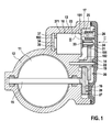
- the actuator shown schematically in Fig. 1 in longitudinal section is used for pivotal adjustment of an actuator which is formed as a throttle valve 11 in the intake of an internal combustion engine.
- the actuator may also be an air damper in an air conditioner or other pivotal element for controlling a channel cross-section.
- the throttle valve 11 is pivotally mounted in a throttle body 12 and by means of the actuator from a basic position, the so-called.
- Emergency or emergency air position in which only a minimal air passage cross-section is released in the throttle body 12, in a Schwenkend ein convertible, in which the available in the throttle body 12 flow cross-section is maximally released.
- the actuator has an integral with the throttle body 12 actuator housing 13 which is covered with a housing cover 14.
- the throttle valve 11 is attached to a control shaft 15 which is pivotally mounted in the throttle body 12 and the actuator housing 13 and carries a gear 16 on its free end.
- a first receiving chamber 17, which is covered by the housing cover 14, and a second receiving chamber 18 is formed, which expires freely toward the first receiving chamber 17.
- a transmission gear 20 is arranged, which comprises an intermediate 19 and a drive pinion 21 in addition to the gear 16.
- the intermediate gear 19 is rotatably mounted on a transmission axis 22, which is accommodated on the one hand in the actuator housing 13 and on the other hand in the housing cover 14.
- the idler 19 has two sprockets 191, 192 with different tooth circle diameter and different numbers of teeth.
- the ring gear 191 with the larger tooth circle diameter meshes with the drive pinion 21, and the ring gear 192 with the smaller ring gear diameter meshes with the gear 16.
- an electric motor 23 is positively inserted, which carries on its projecting into the first receiving chamber 17 motor shaft 24, the drive pinion 21.
- protruding plug contacts of which a plug contact 25 in FIG. can be seen corresponds to mating contacts fixed to the housing cover 14, of which a mating contact 26 can be seen in Fig. 1.
- the contact connections are used for power supply and electrical control of the electric motor 23.
- a slider 27 is mounted on the gear 16, which cooperates with arranged on the housing cover 14 sliding paths of a potentiometer 28.
- This second bearing 34 is either attached to a further bearing flange or held in cup-shaped design of the motor housing 23 in a central opening in the pot bottom. On the mounted in the bearings 33, 34 motor shaft 24 of the stator enclosed rotor of the electric motor 23 is fixed in a known manner.
- the bearing plate 32 distributed over the circumference arranged shield segments 321, of which in Fig. 2 a shield segment and in FIG 3 two shield segments can be seen.
- the shield segments 321 protrude radially beyond the inner wall surface 311 of the cylinder wall 31 and terminate flush with the outer wall surface 312 of the cylinder wall 31.
- the remaining portion of the bearing plate 32 has an outer diameter corresponding to the clear diameter of the motor housing 30.
- the molded in the actuator housing 13 second receiving chamber 18 is by means of a chip tool, for. As a drill, brought to an exact diameter, so that the electric motor 23 is radially play with little effort in the second receiving chamber 18 can be inserted.
- a radially projecting from the cylinder wall 31 annular web 37 is formed.
- the annular web 37 has a central passage opening 38 through which the rear bearing 34 passes when the electric motor 23 is inserted.
- the annular web surface facing the chamber opening 181 forms a contact shoulder 371, on which the motor housing 30 is axially supported with its rear end face.
- a flanging of the shield segments 321 of the bearing plate 32 is made.
- flanging elements 39 arranged along the opening edge of the chamber opening 181 are provided, which are integrally formed on the actuator housing 13. These flaring elements 39 are axially above the chamber opening 181 protruding elevations, which are flattened axially flattening for flaring on the shield segments 321.
- the crimping 39 are shown after flaring on the shield segments 321. 4 shows a crimping element 39 which has not yet been deformed to fix the electric motor 23. The flattening of the elevations by means of a flat tool.
- the material deviates in the direction of the chamber opening 181 and presses against the shield segments 321. In contrast to a beading brought about with a caulking tool, this ensures that no chips are blown off which could cause damage to the gearbox 20.
- the pressing force for deformation of the elevations can be set very accurately, thus the motor housing 30 during the axial setting of the electric motor 23 load very accurately and thus reliably prevent the occurrence of deformations of the motor housing 30.
- the elevations to be deformed are finished with a cutting tool, so that their axial height is set very accurately. This machining of the elevations can be effected simultaneously with the machining of the inner wall of the receiving chamber 18 with a corresponding design of the chip tool in a single operation.
Applications Claiming Priority (1)
| Application Number | Priority Date | Filing Date | Title |
|---|---|---|---|
| DE200610055257 DE102006055257A1 (de) | 2006-11-23 | 2006-11-23 | Stellantrieb für ein Stellorgan |
Publications (2)
| Publication Number | Publication Date |
|---|---|
| EP1925797A1 true EP1925797A1 (de) | 2008-05-28 |
| EP1925797B1 EP1925797B1 (de) | 2010-11-24 |
Family
ID=39166332
Family Applications (1)
| Application Number | Title | Priority Date | Filing Date |
|---|---|---|---|
| EP20070117122 Expired - Fee Related EP1925797B1 (de) | 2006-11-23 | 2007-09-25 | Stellantrieb für ein Stellorgan |
Country Status (2)
| Country | Link |
|---|---|
| EP (1) | EP1925797B1 (pt-PT) |
| DE (2) | DE102006055257A1 (pt-PT) |
Cited By (1)
| Publication number | Priority date | Publication date | Assignee | Title |
|---|---|---|---|---|
| CN114458778A (zh) * | 2022-02-14 | 2022-05-10 | 浙江新华阀门制造有限公司 | 一种基于物联网的智能式调节蝶阀 |
Families Citing this family (2)
| Publication number | Priority date | Publication date | Assignee | Title |
|---|---|---|---|---|
| DE102010042079A1 (de) * | 2010-10-06 | 2012-04-12 | Robert Bosch Gmbh | Gleichstromelektromaschine |
| DE102010042072A1 (de) | 2010-10-06 | 2012-04-12 | Robert Bosch Gmbh | Gleichstromelektromaschine |
Citations (3)
| Publication number | Priority date | Publication date | Assignee | Title |
|---|---|---|---|---|
| DE19525510A1 (de) * | 1995-07-13 | 1997-01-16 | Bosch Gmbh Robert | Drosselklappenstelleinheit |
| EP1126147A2 (en) * | 2000-02-17 | 2001-08-22 | Denso Corporation | Throttle apparatus for internal combustion engine |
| US20050092293A1 (en) * | 2003-10-31 | 2005-05-05 | Denso Corporation | Throttle control apparatus having internally supporting structure |
Family Cites Families (6)
| Publication number | Priority date | Publication date | Assignee | Title |
|---|---|---|---|---|
| DE7404546U (de) * | 1974-08-22 | Stahlschmidt R | Gehäuse für elektrische Maschinen, insbesondere Elektromotor | |
| ES397710A1 (es) * | 1970-12-15 | 1975-03-16 | Frigo | Perfeccionamientos en la construccion de electrocompresoresrotativos a paletas, en particular para avisadores acusti- cos. |
| DE2164084A1 (de) * | 1971-12-23 | 1973-06-28 | Licentia Gmbh | Elektro-kleinmotor |
| DE3123579A1 (de) * | 1981-06-13 | 1982-12-30 | Bosch Gmbh Robert | Aggregat zum foerdern von kraftstoff aus einem vorratstank zu einem verbrennungsmotor |
| DE4241020A1 (de) * | 1992-12-05 | 1994-06-09 | Bosch Gmbh Robert | Drehsteller für Drosselklappe |
| DE19653209A1 (de) * | 1996-12-19 | 1998-06-25 | Siemens Ag | Kommutator-Stellmotor mit hochauflösender Dreherkennung |
-
2006
- 2006-11-23 DE DE200610055257 patent/DE102006055257A1/de not_active Withdrawn
-
2007
- 2007-09-25 DE DE200750005743 patent/DE502007005743D1/de active Active
- 2007-09-25 EP EP20070117122 patent/EP1925797B1/de not_active Expired - Fee Related
Patent Citations (3)
| Publication number | Priority date | Publication date | Assignee | Title |
|---|---|---|---|---|
| DE19525510A1 (de) * | 1995-07-13 | 1997-01-16 | Bosch Gmbh Robert | Drosselklappenstelleinheit |
| EP1126147A2 (en) * | 2000-02-17 | 2001-08-22 | Denso Corporation | Throttle apparatus for internal combustion engine |
| US20050092293A1 (en) * | 2003-10-31 | 2005-05-05 | Denso Corporation | Throttle control apparatus having internally supporting structure |
Cited By (2)
| Publication number | Priority date | Publication date | Assignee | Title |
|---|---|---|---|---|
| CN114458778A (zh) * | 2022-02-14 | 2022-05-10 | 浙江新华阀门制造有限公司 | 一种基于物联网的智能式调节蝶阀 |
| CN114458778B (zh) * | 2022-02-14 | 2023-08-15 | 浙江新华阀门制造有限公司 | 一种基于物联网的智能式调节蝶阀 |
Also Published As
| Publication number | Publication date |
|---|---|
| EP1925797B1 (de) | 2010-11-24 |
| DE502007005743D1 (de) | 2011-01-05 |
| DE102006055257A1 (de) | 2008-05-29 |
Similar Documents
| Publication | Publication Date | Title |
|---|---|---|
| DE19730998C2 (de) | Motorbetätigtes Durchflußmengensteuerventil und Abgasrückführungssteuerventil für Verbrennungsmotoren | |
| DE19510622A1 (de) | Drosselvorrichtung und Verfahren zur Herstellung einer Drosselvorrichtung | |
| WO2010086058A1 (de) | Proportionalmagnet für ein hydraulisches wegeventil und verfahren zu dessen herstellung | |
| EP1797353B1 (de) | Verfahren zur herstellung eines getriebes, sowie ein nach diesem verfahren hergestelltes getriebe | |
| DE202006020694U1 (de) | Verstellbare Nockenwelle | |
| EP1956222B1 (de) | Verfahren zur Montage einer vormontierten Nockenwellenbaugruppe | |
| DE202006018359U1 (de) | Nockenwellenbaugruppe | |
| DE102017102630A1 (de) | Linearschrittmotor, sowie Vorrichtung und Verfahren zur Herstellung eines Linearschrittmotors mit kugelgelagerter Rotorwelle | |
| EP2155532B1 (de) | Kugelgewindetrieb | |
| DE3027627A1 (de) | Kraftstoffeinspritzpumpe fuer eine brennkraftmaschine | |
| EP2094947A1 (de) | Nockenwellenbaugruppe | |
| EP1744082A1 (de) | Stellantrieb, insbesondere für ein Kraftfahrzeug | |
| EP1789280A1 (de) | Getriebe-antriebseinheit | |
| DE10336976B4 (de) | Ventilvorrichtung für eine Verbrennungskraftmaschine | |
| EP1925797B1 (de) | Stellantrieb für ein Stellorgan | |
| EP3227540A1 (de) | Klappenvorrichtung für eine verbrennungskraftmaschine | |
| WO2018206631A1 (de) | Stelleinrichtung und zugehöriges herstellungsverfahren | |
| DE10295941B3 (de) | Solenoidventil | |
| DE10330449B3 (de) | Nockenwellenversteller | |
| DE102018123045A1 (de) | Elektrischer Kupplungsaktuator mit Getriebelagerplatte | |
| EP1826375B1 (de) | Schaltventil und zugehöriges Herstellungsverfahren | |
| WO2010149526A2 (de) | Kommutatorlager | |
| DE102009057331A1 (de) | Exzenter-Spannvorrichtung | |
| EP2997646A1 (de) | Antriebseinrichtung, insbesondere stelleinrichtung in einem fahrzeug | |
| DE102007059558A1 (de) | Gewindespindel-Verstellantrieb |
Legal Events
| Date | Code | Title | Description |
|---|---|---|---|
| PUAI | Public reference made under article 153(3) epc to a published international application that has entered the european phase |
Free format text: ORIGINAL CODE: 0009012 |
|
| AK | Designated contracting states |
Kind code of ref document: A1 Designated state(s): AT BE BG CH CY CZ DE DK EE ES FI FR GB GR HU IE IS IT LI LT LU LV MC MT NL PL PT RO SE SI SK TR |
|
| AX | Request for extension of the european patent |
Extension state: AL BA HR MK RS |
|
| 17P | Request for examination filed |
Effective date: 20081128 |
|
| AKX | Designation fees paid |
Designated state(s): CZ DE FR IT |
|
| GRAP | Despatch of communication of intention to grant a patent |
Free format text: ORIGINAL CODE: EPIDOSNIGR1 |
|
| GRAS | Grant fee paid |
Free format text: ORIGINAL CODE: EPIDOSNIGR3 |
|
| GRAA | (expected) grant |
Free format text: ORIGINAL CODE: 0009210 |
|
| AK | Designated contracting states |
Kind code of ref document: B1 Designated state(s): CZ DE FR IT |
|
| REF | Corresponds to: |
Ref document number: 502007005743 Country of ref document: DE Date of ref document: 20110105 Kind code of ref document: P |
|
| PG25 | Lapsed in a contracting state [announced via postgrant information from national office to epo] |
Ref country code: CZ Free format text: LAPSE BECAUSE OF FAILURE TO SUBMIT A TRANSLATION OF THE DESCRIPTION OR TO PAY THE FEE WITHIN THE PRESCRIBED TIME-LIMIT Effective date: 20101124 |
|
| PLBE | No opposition filed within time limit |
Free format text: ORIGINAL CODE: 0009261 |
|
| STAA | Information on the status of an ep patent application or granted ep patent |
Free format text: STATUS: NO OPPOSITION FILED WITHIN TIME LIMIT |
|
| 26N | No opposition filed |
Effective date: 20110825 |
|
| REG | Reference to a national code |
Ref country code: DE Ref legal event code: R097 Ref document number: 502007005743 Country of ref document: DE Effective date: 20110825 |
|
| REG | Reference to a national code |
Ref country code: FR Ref legal event code: PLFP Year of fee payment: 10 |
|
| PGFP | Annual fee paid to national office [announced via postgrant information from national office to epo] |
Ref country code: FR Payment date: 20160922 Year of fee payment: 10 |
|
| PGFP | Annual fee paid to national office [announced via postgrant information from national office to epo] |
Ref country code: DE Payment date: 20161125 Year of fee payment: 10 |
|
| PGFP | Annual fee paid to national office [announced via postgrant information from national office to epo] |
Ref country code: IT Payment date: 20160922 Year of fee payment: 10 |
|
| REG | Reference to a national code |
Ref country code: DE Ref legal event code: R119 Ref document number: 502007005743 Country of ref document: DE |
|
| REG | Reference to a national code |
Ref country code: FR Ref legal event code: ST Effective date: 20180531 |
|
| PG25 | Lapsed in a contracting state [announced via postgrant information from national office to epo] |
Ref country code: DE Free format text: LAPSE BECAUSE OF NON-PAYMENT OF DUE FEES Effective date: 20180404 |
|
| PG25 | Lapsed in a contracting state [announced via postgrant information from national office to epo] |
Ref country code: IT Free format text: LAPSE BECAUSE OF NON-PAYMENT OF DUE FEES Effective date: 20170925 Ref country code: FR Free format text: LAPSE BECAUSE OF NON-PAYMENT OF DUE FEES Effective date: 20171002 |