-
The present invention relates to a contactless optical writing apparatus for recording information on a rewritable thermal recording medium, the apparatus enabling recording and erasure of information in a contactless manner without direct contact with a heating device such as a thermal head.
-
There is a thermal recording system in which a diazo compound-based heat-sensitive material is utilized. There are reversible thermal recording paper and the like that enable repeating of color development and color disappearance at a specific temperature. In the thermal recording paper, color development and color disappearance take place by heating by means of a heating device such as a thermal head. As a recording system for such thermal recording paper, there is a system in which a recording head such a thermal head is brought into direct contact with the thermal recording paper. In this system, the recording head is brought into direct contact with the thermal recording paper, and hence the following problems are brought about.
For example, wear and stain of the recording head are easily caused. Further, the printing surface of the thermal recording paper is rubbed and stained. The service life of the recording head is shortened due to a short circuit caused by an accretion or excessive power supply or the like.
-
On the other hand, as a technique of information recording using thermal recording paper, there are techniques disclosed in, for example,
Japanese Patent No. 3266922 and
Japanese Patent No. 2561098 .
Japanese Patent No. 3266922 relates to a method of developing and disappearing a color in a contactless manner by using a reversible heat-sensitive material, and discloses an information recording medium in which an infrared absorbing layer that absorbs infrared rays to generate heat and a thermal recording layer are stacked in sequence on a substrate. Of these layers, the thermal recording layer is constituted of a heat-sensitive color development layer or a metallic thin film. The thermal recording layer develops or changes a color or is melted and removed by heat of the infrared absorbing layer. Further, Pat.
Document 1 discloses a recording method in which an infrared absorbing layer is caused to generate heat by irradiation of infrared laser light, and a thermal recording layer develops or changes a color or is melted and removed by this heat.
-
Japanese Patent No. 2561098 relates to a laser beam recording apparatus for performing image recording on a heat mode recording material, which comprises first and second semiconductor lasers for emitting laser beam spreading in a direction perpendicular to a pn junction plane and having an elliptic cross-sectional shape, a deflection beam splitter for combining the laser beams emitted from the semiconductor lasers, and a scanning optical system for scanning by using the laser beam combined by the deflection beam splitter. In the laser beam recording apparatus disclosed in
Japanese Patent No. 2561098 , the laser beam emitted from the first semiconductor laser and the laser beam emitted from the second semiconductor laser are combined with each other, and the semiconductor lasers are arranged in such a manner that a center of the combined laser beam is shifted to one end side in a major axis direction of a cross-sectional shape of one of the laser beams. Further, Pat.
Document 2 discloses that main scanning is performed by the scanning optical system in a state where the center of the combined laser beam is positioned on the rear side in the direction of movement in the major axis direction of the cross-sectional shape of one of the laser beams.
-
However, in
Japanese Patent No. 3266922 , a laser having a high power output is required as a light source for outputting infrared laser light. For this reason, in
Japanese Patent No. 3266922 , even when a semiconductor laser small in size and relatively low in price is used, it is a fact that the output is limited to several watts with this semiconductor laser, and a recording speed of the line-type thermal head class cannot be realized. There is a method in which for example, a YAG laser or the like having an output equal to or larger than several tens of watts is used. However, when a YAG laser or the like is used, the price is higher than the semiconductor laser, and the apparatus becomes larger.
-
In
Japanese Patent No. 2561098 , the shapes of the laser beams emitted from the first and second semiconductor lasers are elliptic on the recording surface of the heat mode recording material, and are perpendicular to each other in the major axis directions. For this reason, the power of one semiconductor laser having the major axis in the main scanning direction of the laser beam is used for heat recording. However, the power of the other semiconductor laser having the major axis in the sub-scanning direction is not effectively used for heat recording in a part other than a part in which the other semiconductor laser overlaps with the one semiconductor laser. Further, in
Japanese Patent No. 2561098 , the laser beams are combined with each other by the deflection beam splitter, and hence the number of laser beams to be combined is limited to two.
-
An object of the present invention is to provide a contactless optical writing apparatus which can resolve the problem of deficient power at the time of thermal recording on a thermal recording medium by effectively utilizing power of a laser beam and can realize enhancement of the recording speed.
-
A contactless optical writing apparatus according to a main aspect of the present invention comprises: a first semiconductor laser for outputting a first semiconductor laser beam; a first condensing lens for condensing the first semiconductor laser beam; a second semiconductor laser for outputting a second semiconductor laser beam; a second condensing lens for condensing the second semiconductor laser beam; a laser beam combining element for combining the first semiconductor laser beam condensed by the first condensing lens and the second semiconductor laser beam condensed by the second condensing lens with each other, and outputting the combined semiconductor laser beam; and a deflection scanning mechanism for scanning a surface of a thermal recording medium which when heated to a color development temperature higher than the normal temperature, develops a color, and when heated to a color disappearance temperature lower than the color development temperature while the thermal recording medium is kept in a color development state at the normal temperature, disappears the color by using the combined semiconductor laser beam output from the laser beam combining element, wherein the first semiconductor laser has a junction plane of active layers for outputting the first semiconductor laser beam, the second semiconductor laser has a junction plane of active layers for outputting the second semiconductor laser beam, a junction plane direction of the first semiconductor laser and a junction plane direction of the second semiconductor laser are perpendicular to or parallel to a direction of the scanning performed by the deflection scanning mechanism by using the combined semiconductor laser beam, the first semiconductor laser beam has one of output power capable of heating the thermal recording medium to a temperature equal to or lower than the color disappearance temperature by irradiating the thermal recording medium therewith and output power capable of heating the thermal recording medium up to the color disappearance temperature, the second semiconductor laser beam has one of output power capable of heating the thermal recording medium up to the color disappearance temperature by irradiating the thermal recording medium therewith and output power capable of heating the thermal recording medium to a temperature equal to or lower than the color disappearance temperature, and the apparatus has output power capable of heating the thermal recording medium up to the color development temperature by combining the first semiconductor laser beam and the second semiconductor laser beam into a combined semiconductor laser beam and irradiating the thermal recording medium with the combined semiconductor laser beam.
-
The invention can be more fully understood from the following detailed description when taken in conjunction with the accompanying drawings, in which:
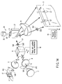
- FIG. 1 is a configuration view showing a first embodiment of a contactless optical writing apparatus according to the present invention.
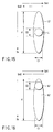
- FIG. 2 is a configuration view of a single mode semiconductor laser in the contactless optical writing apparatus.
- FIG. 3 is a configuration view of a multimode semiconductor laser in the contactless optical writing apparatus.
- FIG. 4 is a view showing a beam profile of a laser beam formed by combining a single mode laser beam and a multimode laser beam with each other by the contactless optical writing apparatus on a thermal recording medium.
- FIG. 5 is a view showing a beam profile of a laser beam formed by combining a single mode laser beam and a multimode laser beam with each other by the contactless optical writing apparatus on a thermal recording medium.
- FIG. 6 is a view showing a recording/erasing characteristic of the thermal recording medium in the contactless optical writing apparatus.
- FIG. 7 is a graph showing a relationship between a medium temperature and color development/color disappearance obtained when the thermal recording medium is irradiated with the single mode laser beam and the multimode laser beam of the contactless optical writing apparatus.
- FIG. 8A is a view showing a function of a beam spot position varying mechanism in the contactless optical writing apparatus.
- FIG. 8B is a view showing a function of a beam spot position varying mechanism in the contactless optical writing apparatus.
- FIG. 8C is a view showing a function of a beam spot position varying mechanism in the contactless optical writing apparatus.
- FIG. 8D is a view showing a function of a beam spot position varying mechanism in the contactless optical writing apparatus.
- FIG. 9 is a configuration view showing a second embodiment of a contactless optical writing apparatus according to the present invention.
- FIG. 10 is a view showing a beam profile of a laser beam formed by combining a single mode laser beam and a multimode laser beam with each other by the contactless optical writing apparatus on a thermal recording medium.
- FIG. 11 is a view showing a beam profile of a laser beam formed by combining a single mode laser beam and a multimode laser beam with each other by the contactless optical writing apparatus on a thermal recording medium.
- FIG. 12 is a configuration view showing a third embodiment of a contactless optical writing apparatus according to the present invention.
- FIG. 13 is a configuration view showing a fourth embodiment of a contactless optical writing apparatus according to the present invention.
- FIG. 14 is a configuration view showing a fifth embodiment of a contactless optical writing apparatus according to the present invention.
- FIG. 15 is a view showing a beam profile of a laser beam formed by combining a single mode laser beam and a multimode laser beam with each other by the contactless optical writing apparatus on a thermal recording medium.
- FIG. 16 is a view showing a beam profile of a laser beam formed by combining a single mode laser beam and a multimode laser beam with each other by the contactless optical writing apparatus on a thermal recording medium.
- FIG. 17 is a configuration view showing a sixth embodiment of a contactless optical writing apparatus according to the present invention.
- FIG. 18 is a configuration view showing a seventh embodiment of a contactless optical writing apparatus according to the present invention.
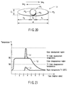
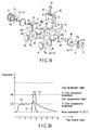
- FIG. 19 is a graph showing a wavelength versus reflectance characteristic of a dichroic prism in the contactless optical writing apparatus.
- FIG. 20 is a view showing a beam profile of a combined laser beam formed on a thermal recording medium by the contactless optical writing apparatus.
- FIG. 21 is a graph showing a relationship between a medium temperature and color development/color disappearance obtained when the thermal recording medium is irradiated with the single mode laser beam and the multimode laser beam of the contactless optical writing apparatus.
- FIG. 22 is a configuration view showing an eighth embodiment of a contactless optical writing apparatus according to the present invention.
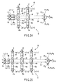
- FIG. 23 is a configuration view showing a ninth embodiment of a contactless optical writing apparatus according to the present invention.
- FIG. 24 is a configuration view showing a tenth embodiment of a contactless optical writing apparatus according to the present invention.
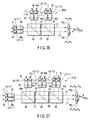
- FIG. 25 is a configuration view showing an eleventh embodiment of a contactless optical writing apparatus according to the present invention.
- FIG. 26 is a configuration view showing a twelfth embodiment of a contactless optical writing apparatus according to the present invention.
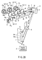
- FIG. 27 is a configuration view showing a thirteenth embodiment of a contactless optical writing apparatus according to the present invention.
- FIG. 28 is a configuration view showing a fourteenth embodiment of a contactless optical writing apparatus according to the present invention.
- FIG. 29 is a configuration view showing a fifteenth embodiment of a contactless optical writing apparatus according to the present invention.
- FIG. 30 is a graph showing another relationship between a medium temperature and color development/color disappearance obtained when the thermal recording medium is irradiated with the single mode laser beam and the multimode laser beam of the contactless optical writing apparatus of the present invention.
-
A first embodiment of the present invention will be described below with reference to the accompanying drawings.
-
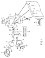
FIG. 1 shows a configuration view of a contactless optical writing apparatus. The contactless optical writing apparatus comprises a single mode semiconductor laser 2 and a multimode semiconductor laser 3 as light sources for emitting laser light with which a thermal recording medium 1 is irradiated. Each of the semiconductor laser 2 and 3 outputs a laser beam having a light emission wavelength in the near-infrared region, for example, a region from 750 nm to 1000 nm, and having high output power of about several watts. Each of the semiconductor lasers 2 and 3 has the same characteristics as those of semiconductor lasers (laser diodes: LDs) which are already used in, for example, a laser printer, laser pointer, DVD player, and the like in large numbers, i.e., a spread angle, output-current characteristic, and temperature characteristic. In each of the semiconductor lasers 2 and 3, an output of the laser beam is large. Hence, in each of the semiconductor lasers 2 and 3, an amount of a supplied current is large in the ampere class, and an amount of generated heat becomes large, thereby necessitating cooling. Accordingly, each of the semiconductor lasers 2 and 3 is fixed to a radiator plate, and the radiator plate is forcedly cooled.
-
A collimator lens 4, a polarization beam splitter 5 serving as a laser beam combining element, a deflection scanning mechanism 7, and a scanning lens 8 are provided between the single mode semiconductor laser 2 and the thermal recording medium 1 along a laser light irradiation optical path between the single mode semiconductor laser 2 and the thermal recording medium 1. A collimator lens 9, the polarization beam splitter 5, the deflection scanning mechanism 7, and the scanning lens 8 serving as an condensing lens are provided between the multimode semiconductor laser 3 and the thermal recording medium 1 along a laser light irradiation optical path between the multimode semiconductor laser 3 and the thermal recording medium 1.
-
The polarization beam splitter 5 reflects the single mode laser beam L1 output from the single mode semiconductor laser 2, and transmits the multimode laser beam L2 output from the multimode semiconductor laser 3.
-
The deflection scanning mechanism 7 includes a polygon mirror 10 serving as a deflecting member, and a rotary drive section 12. The polygon mirror 10 is coupled to the rotary drive section 12 through a rotating shaft 11. The rotary drive section 12 rotates the polygon mirror 10 through the rotating shaft 11 in one direction, for example, a direction indicated by an arrow f.
-
The single mode semiconductor laser 2 includes a laser emitting section 13 for outputting the single mode laser beam L1 as shown in FIG. 2. In the laser emitting section 13, a pn junction plane (junction plane of active layers) 14 is formed. In the single mode semiconductor laser 2, the junction plane direction of the pn junction plane 14 of the laser emitting section 13 is arranged parallel with the rotating shaft of the deflecting member of the deflection scanning mechanism 7, i.e., the rotating shaft of the polygon mirror 10.
-
The polarization direction Sd1 of the single mode laser beam L1 is the same as the junction plane direction of the pn junction plane 14. The polarization direction Sd1 of the single mode laser beam L1 is perpendicular to the polarization beam splitter 5. The single mode laser beam L1 is of S-polarization with respect to the polarization beam splitter 5. Accordingly, the polarization beam splitter 5 reflects the single mode laser beam L1 output from the single mode semiconductor laser 2.
-
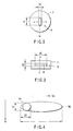
The size of a light emitting region in the laser emitting section 13 of the single mode semiconductor laser 2 is, as shown in FIG. 2, about several µm in, for example, the junction plane direction a1 of the pn junction plane 14 and in the direction b1 perpendicular to the junction plane direction a1. More specifically, as for the size of the light emitting region of the laser emitting section 13, a1 in the junction plane direction is about 3 µm, and b1 in the direction perpendicular to the junction plane direction is about 1 µm. The single mode laser beam L1 emitted from the laser emitting section 13 spreads with a profile Pf1 shown in FIG. 1 as it advances. The beam profile Pf1 has a Gaussian distribution.
-
The multimode semiconductor laser 3 includes a laser emitting section 15 for outputting the multimode laser beam L2 as shown in FIG. 3. A pn junction plane 16 is formed in the laser emitting section 15. The multimode semiconductor laser 3 is arranged in such a manner that the junction plane direction of the pn junction plane 16 in the light emitting region is perpendicular to the rotating shaft of the deflecting member of the deflection scanning mechanism, i.e., the rotating shaft 11 of the polygon mirror 10. In other words, the multimode semiconductor laser 3 is arranged perpendicular to the junction plane direction of the pn junction plane 14 in the light emitting region of the single mode semiconductor laser 2.
-
The polarization direction Sd2 of the multimode laser beam L2 is the same as the junction plane direction of the pn junction plane 16. The polarization direction Sd2 of the multimode laser beam L2 is perpendicular to the rotating shaft 11 of the polygon mirror 10. The polarization direction Sd2 of the multimode laser beam L2 output from the laser emitting section 15 is horizontal direction with the polarization beam splitter 5. The multimode laser beam L2 is of p-polarization with respect to the polarization beam splitter 5. Accordingly, the polarization beam splitter 5 reflects the multimode laser beam L2 output from the multimode semiconductor laser 3.
-
In the light emitting region in the laser emitting section 15 of the multimode semiconductor laser 3, as shown in FIG. 3, for example, a2 in the junction plane direction of the pn junction plane (junction plane of active layers) and b2 in the direction perpendicular to the junction plane direction a2 are different from each other. More specifically, as for the size of the light emitting region of the laser emitting section 15, a2 in the junction plane direction is about 50 to 200 µm, and b2 in the direction perpendicular to the junction plane direction is about 1 µm. The multimode laser beam L2 emitted from the laser emitting section 15 spreads with a profile Pf2 shown in FIG. 1 as it advances. The beam profile Pf2 has no fine Gaussian distribution. The multimode semiconductor laser 3 is provided on a mount 17.
-
The first collimator lens 4 is provided on the progression optical path of the single mode laser beam L1 output from the single mode semiconductor laser 2. The first collimator lens 4 condense the single mode laser beam L1 output from the single mode semiconductor laser 2 into a substantially parallel light flux.
-
The second collimator lens 9 is provided on the progression optical path of the multimode laser beam L2 output from the multimode semiconductor laser 3. The second collimator lens 9 condense the multimode laser beam L2 output from the multimode semiconductor laser 3 into a substantially parallel light flux.
-
The polarization beam splitter 5 is provided at an intersection position at which the progression optical path of the single mode laser beam L1 output from the single mode semiconductor laser 2 and the progression optical path of the multimode laser beam L2 output from the multimode semiconductor laser 3 intersect each other. The single mode laser beam L1 output from the single mode semiconductor laser 2 and the multimode laser beam L2 output from the multimode semiconductor laser 3 are incident on the polarization beam splitter 5. However, the polarization beam splitter 5 reflects the single mode laser beam L1 output from the single mode semiconductor laser 2, further transmits the multimode laser beam L2 output from the multimode semiconductor laser 3, and outputs a combined laser beam L3 formed by combining the single mode laser beam L1 and the multimode laser beam L2 with each other.
-
The deflection scanning mechanism 7 scans, as the main scanning, the thermal recording medium 1 by using the combined laser beam L3 output from the polarization beam splitter 5 by means of the rotation of the polygon mirror 10 in the direction indicated by the arrow f. The multimode semiconductor laser 3 is set to such a direction that the polarization direction Sd2 of the P-polarization of the multimode laser beam L2 is perpendicular to the direction of the rotating shaft 11 of the polygon mirror 10. As a result of this, the deflection scanning mechanism 7 performs the main scanning by using the combined laser beam L3 in the same direction as the polarization direction Sd2 of the multimode laser beam L2. That is, the direction Sm of the main scanning performed by the deflection scanning mechanism 7 using the combined laser beam L3 and the polarization direction Sd2 of the multimode laser beam L2 coincide with each other. As a result of this, the oblong shape longitudinal direction of the beam profile Pf2 of the multimode laser beam L2 coincides with the main scanning direction Sm on the thermal recording medium 1.
-
However, the multimode semiconductor laser 3 is arranged in such a manner that the junction plane direction of the pn junction plane 16 of the laser emitting section 15 is parallel with the direction of the main scanning performed by the deflection scanning mechanism 7 using the combined laser beam L3. Further, the single mode semiconductor laser 2 is arranged in such a manner that the junction plane direction of the pn junction plane 14 is perpendicular to the junction plane direction of the pn junction plane 16 of the multimode semiconductor laser 3.
-
The scanning lens 8 is arranged within the scanning range in the direction Sm of the main scanning performed by the deflection scanning mechanism 7 using the combined laser beam L3. The scanning lens 8 forms an image of the combined laser beam L3 used by the deflection scanning mechanism 7 for the main scanning on the surface of the thermal recording medium 1. That is, images of the laser beam L1 and the laser beam L2 included in the combined laser beam L3 are respectively formed on the surface of the thermal recording medium 1 by the scanning lens 8.
-
FIGS. 4 and 5 respectively show beam profiles of the single mode laser beam L1 and the multimode laser beam L2 formed on the thermal recording medium 1 by the scanning lens 8. The single mode laser beam L1 is formed as a circular beam profile Pf1 on the thermal recording medium 1. The multimode laser beam L2 is formed as an oblong beam profile Pf2 on the thermal recording medium 1.
-
The shape of the laser emitting section 13 of the single mode semiconductor laser 2 has a length of about several µm in each of the direction parallel with the pn junction plane 14 and the direction perpendicular thereto. Accordingly, it is easy to make the beam profile of the single mode laser beam L1 a small and substantially circular shape by condensing the single mode laser beam L1 by means of the scanning lens 8.
For example, the single mode laser beam L1 is condensed into a substantially circular shape of about 100 µm (1/e2).
-
On the other hand, the shape of the laser emitting section 15 of the multimode semiconductor laser 3 has a larger length in the direction parallel with the pn junction plane 16 than the length in the direction perpendicular to the pn junction plane, and furthermore, the larger length is, for example, as large as about 50 to 200 µm. For this reason, it is difficult to make the beam profile Pf2 of the multimode laser beam L2 a small and substantially circular shape by condensing the multimode laser beam L2 by means of the scanning lens 8. Therefore, the beam profile Pf2 of the multimode laser beam L2 becomes a shape oblong in the direction of the pn junction plane 16.
-
Accordingly, as shown in FIGS. 4 and 5, an image of the combined laser beam L3 is formed on the thermal recording medium 1 as a form in which a substantially circular beam profile Pf1 is superposed on an oblong beam profile Pf2.
-
Incidentally, each of the single mode laser beam L1 and the multimode laser beam L2 has a profile of a substantially Gaussian distribution. It is advisable to vary the combining position in the beam profile Pf2 of the multimode laser beam L2 at which the multimode laser beam L2 is combined with the single mode laser beam L1 in accordance with recording conditions and environmental conditions. Further, when the single mode laser beam L1 is condensed into a substantially circular shape of about 100 µm (1/e2), the combination is not limited to the case where the single mode laser beam L1 and the multimode laser beam L2 are combined with each other in a superposing manner, and they may be combined with each other so as to be close to each other. In this case, it is desirable that central positions of the single mode laser beam L1 and the multimode laser beam L2 be aligned with each other in the sub-scanning direction Ss.
-
FIG. 5 shows a profile of a combined beam formed by combining the single mode laser beam L1 having a circular beam profile Pf1 with the multimode laser beam L2 within the oblong beam profile Pf2 of the multimode laser beam L2 at a central position on the thermal recording medium 1 in the main scanning direction (scanning direction) Sm. In this combined beam profile, the center of the single mode laser beam L1 and the center (peak of power) of the multimode laser beam L2 coincide with each other. In such a combination of the single mode laser beam L1 and the multimode laser beam L2, it is possible to cause the instantaneous power peaks of the single mode laser beam L1 and the multimode laser beam L2 coincide with each other. As a result, it is possible to improve the utilization efficiency of the laser beam energy.
-
Incidentally, the beam profile Pf1 of the beam used in the scanning on the thermal recording medium 1 is formed so as to allow both a beam size c1 in the height direction and a beam size c2 in the lateral direction to be, for example, about 100 µm as shown in FIG. 4. The beam profile Pf2 of the beam used in the scanning on the thermal recording medium 1 is formed so as to allow a beam size c1 in the height direction to be, for example, about 100 µm, and a beam size d in the lateral direction to be, for example, a little over 1 mm as shown in FIG. 5.
-
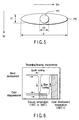
The thermal recording medium 1 is a rewritable and reversible medium which enables repeating of color development and color disappearance by heating control at a specific temperature, and enables thermal recording and thermal erasure. As shown in FIG. 6, when the thermal recording medium 1 is subjected to a temperature higher than the melting point 180°C, the thermal recording medium 1 is set to a state where a dye and a developer contained in the printing layer melt together. When the thermal recording medium 1 is quickly cooled in this state, the mixture of the dye and the developer is crystallized as it is, thereby developing a color. On the other hand, when the thermal recording medium 1 is slowly cooled, each of the dye and the developer is separately crystallized. As a result, the thermal recording medium 1 cannot maintain the color development state, thereby setting the thermal recording medium 1 to the color disappearance state. Further, when the thermal recording medium is heated at a temperature lower than the melting points of the dye and the developer for a fixed period of time, the dye and the developer are gradually separated from each other so as to be crystallized, thereby setting the thermal recording medium 1 to the color disappearance state in some cases. The temperature of the color disappearance region is, for example, about 130°C to 180°C.
-
FIG. 7 shows a relationship between the temperature on the thermal recording medium 1 and the color development/color disappearance obtained when the thermal recording medium 1 is irradiated with the single mode laser beam L1 and the combined laser beam L3. When heated, starting from the room temperature Tr (for example, 25°C), at a temperature higher than the color development temperature T2 (for example, 180°C), and then quickly cooled, the thermal recording medium 1 develops a color. When the thermal recording medium 1 in the the color development state is heated, starting from the room temperature Tr, temporarily at the color disappearance temperature T1 (for example, 130°C) lower than the color development temperature T2, and then cooled, the color is disappeared.
-
However, the single mode laser beam L1 singly has output power capable of heating the printing layer of the thermal recording medium 1 up to a temperature equal to or lower than the color disappearance temperature T1 by irradiating the thermal recording medium 1 therewith. The thermal recording medium 1 does not develop a color by the power.
-
On the other hand, the multimode laser beam L2 singly has output power capable of heating the printing layer of the thermal recording medium 1 up to the color disappearance temperature T1 by irradiating the thermal recording medium 1 therewith, although the color disappearance temperature T1 is equal to or lower than the color development temperature T2. As a result, the temperature rise to be observed when the thermal recording medium 1 is irradiated singly with the multimode laser beam L2 is equal to or higher than the color disappearance temperature T1 and equal to or lower than the color development temperature T2, and hence the temperature of the thermal recording medium 1 is raised to the color disappearance region in which the developed color of the thermal recording medium 1 can be disappeared.
-
Incidentally, when the single mode laser beam L1 has output power capable of heating the thermal recording medium 1 up to a temperature lower than the color disappearance temperature T1, the multimode laser beam L2 has output power capable of heating the thermal recording medium 1 up to the color disappearance temperature T1 by irradiating the thermal recording medium 1 therewith. When the single mode laser beam L1 has output power capable of heating the thermal recording medium 1 up to the color disappearance temperature T1 by irradiating the thermal recording medium 1 therewith, the multimode laser beam L2 has output power capable of heating the thermal recording medium 1 up to a temperature lower than the color disappearance temperature T1.
-
When the thermal recording medium 1 is subjected to the main scanning using the combined laser beam L3, the thermal recording medium 1 is first irradiated with the multimode laser beam L2. As a result, the printing layer of the thermal recording medium 1 is quickly heated up to the color disappearance temperature T1.
-
Then, the thermal recording medium 1 is irradiated with superposition of the multimode laser beam L2 and the single mode laser beam L1. As a result, the printing layer of the thermal recording medium 1 in the state where it is heated up to the color disappearance temperature T1 is further heated quickly up to the color development temperature T2.
-
Then, the irradiation of the superposition of the multimode laser beam L2 and the single mode laser beam L1 is terminated. Subsequently, the irradiation of the multimode laser beam L2 is terminated. As a result, the printing layer of the thermal recording medium 1 is quickly cooled. Thus, it becomes possible to record information on the thermal recording medium 1 while erasing information originally recorded on the thermal recording medium 1.
-
A transfer mechanism 19 transfers the thermal recording medium 1 in the same direction as the sub-scanning direction Ss at, for example, a fixed transfer speed. The sub-scanning direction Ss is perpendicular to the main scanning direction Sm.
-
Incidentally, when the transfer speed of the thermal recording medium 1 becomes lower, energy per unit area of the laser beam with which the thermal recording medium 1 is irradiated becomes larger. That is, the product of the power and the irradiation time of the multimode laser beam L2 and the single mode laser beam L1 becomes larger. On the other hand, the output power is increased or decreased depending on the combination of the single mode laser beam L1 output from the single mode semiconductor laser 2 and the multimode laser beam L2 output from the multimode semiconductor laser 3. Accordingly, the transfer speed of the thermal recording medium 1 is set in accordance with the output power of each of the single mode semiconductor laser 2 and the multimode semiconductor laser 3 in such a manner that the thermal recording medium 1 is heated up to the color disappearance temperature T1 by irradiation of the multimode laser beam L2, and the thermal recording medium 1 is heated at the color development temperature T2 by subsequent irradiation of the single mode laser beam L1.
-
A beam spot position varying mechanism 18 varies the combining position of the beam profile Pf1 in the beam profile Pf2 of the multimode laser beam L2. The beam spot position varying mechanism 18 moves the polarization beam splitter 5 in the traveling direction h of the multimode laser beam L2 output from the multimode semiconductor laser 3. Alternatively, the beam spot position varying mechanism 18 moves the polarization beam splitter 5 in the traveling direction of the single mode laser beam L1. The beam spot position varying mechanism 18 varies the combining position of the beam spot Pf1 by rotating the polarization beam splitter 5 around a rotation axis parallel with the polarization direction Sd1 of the S-polarization.
-
FIGS. 8A to 8D each show a positional relationship of combination between the multimode laser beam L2 and the single mode laser beam L1 which are image-formed on the thermal recording medium 1 and moved by the beam spot position varying mechanism 18. In FIG. 8A, the combining position of the beam spot Pf1 is the central position of the beam profile Pf2 of the multimode laser beam L2. When the polarization beam splitter 5 is moved in the traveling direction h of the multimode laser beam L2 from this state as shown in FIG. 8B, the incidence position of the single mode laser beam L1 on the polarization beam splitter 5 is changed. In response to this, the reflection position of the single mode laser beam L1 in the polarization beam splitter 5 is changed. As a result, the combining position of the beam spot Pf1 in the beam profile Pf2 of the multimode laser beam L2 is varied.
-
FIG. 8C shows the combining position of the beam spot Pf1 in the beam profile Pf2 of the multimode laser beam L2 observed when the polarization beam splitter 5 is moved in the traveling direction h' of the first semiconductor laser beam. FIG. 8D shows the combining position of the beam spot Pf1 in the beam profile Pf2 of the multimode laser beam L2 observed when the polarization beam splitter 5 is rotated in the rotational direction r around a rotation axis parallel with the vibration direction of the S-polarization of the single mode laser beam L1.
-
Next, a recording operation performed by the apparatus configured as described above.
-
The single mode semiconductor laser 2 outputs a single mode laser beam L1 of the S-polarization from the laser emitting section 13 to the polarization beam splitter 5. The single mode laser beam L1 has a polarization direction Sd1 of the S-polarization identical with the junction plane direction of the pn junction plane 14. The single mode laser beam L1 is condensed into a substantially parallel light flux by the first collimator lens 4, and is made incident on the polarization beam splitter 5.
-
On the other hand, the multimode semiconductor laser 3 outputs a multimode laser beam L2 of the P-polarization from the laser emitting section 15 to the polarization beam splitter 5. The multimode laser beam L2 has a polarization direction Sd2 of P-polarization identical with the junction plane direction of the pn junction plane 16. The multimode laser beam L2 is condensed into a substantially parallel light flux by the second collimator lens 9, and is made incident on the polarization beam splitter 5.
-
The polarization beam splitter 5 reflects the single mode laser beam L1 output from the single mode semiconductor laser 2, transmits the multimode laser beam L2 output from the multimode semiconductor laser 3, and outputs them as the combined laser beam L3. The combined laser beam L3 output from the polarization beam splitter 5 is made incident on the deflection scanning mechanism 7.
-
The deflection scanning mechanism 7 continuously rotates the polygon mirror 10 in the arrow direction f by the drive of the rotary drive section 12 through the rotating shaft 11. As a result of this, the polygon mirror 10 scans the thermal recording medium 1 in the main scanning direction Sm by using the combined laser beam L3 output from the polarization beam splitter 5. The multimode semiconductor laser 3 is set in such a manner that the polarization direction Sd2 of the P-polarization of the multimode laser beam L2 is perpendicular to the direction of the rotating shaft 11 of the polygon mirror 10. As a result of this, the deflection scanning mechanism 7 performs the main scanning by using the combined laser beam L3 in the same direction as the polarization direction Sd2 of the multimode laser beam L2.
-
The scanning lens 8 forms the image of the combined laser beam L3 used by the deflection scanning mechanism 7 for the main scanning on the surface of the thermal recording medium 1 as shown in FIGS. 4 and 5. That is, the image of the combined laser beam L3 is formed on the surface of the thermal recording medium 1 as a form in which a circular beam profile Pf1 is superposed on an oblong beam profile Pf2 of the multimode laser beam L2.
-
The combined laser beam L3 an image of which is formed on the thermal recording medium 1 is used to scan the thermal recording medium 1 in the same direction as the oblong shape longitudinal direction of the beam profile Pf2 of the multimode laser beam L2. When the main scanning is performed on the thermal recording medium 1 using the combined laser beam L3, the surface of the thermal recording medium 1 is first irradiated singly with the multimode laser beam L2 included in the combined laser beam L3. The temperature on the surface of the thermal recording medium 1 observed when the medium 1 is irradiated singly with the multimode laser beam L2 is equal to or lower than the color development temperature T2 as shown in FIG. 7, the thermal recording medium 1 is quickly heated up to the color disappearance temperature T1, and hence the temperature is raised.
-
Then, the surface of the thermal recording medium 1 is irradiated with superposition of the multimode laser beam L2 and the single mode laser beam L1 included in the combined laser beam L3. The thermal recording medium 1 is further quickly heated up to the color development temperature T2 from the state where it is heated up to the color disappearance temperature T1, and hence the temperature on the surface of the thermal recording medium 1 observed at this time is raised. As a result, it becomes possible to record information on the thermal recording medium 1.
-
Then, the irradiation of the single mode laser beam L1 is terminated, subsequently the irradiation of the multimode laser beam L2 is terminated, and the printing layer of the thermal recording medium 1 is quickly cooled. As a result, a part of the printing layer of the thermal recording medium 1 irradiated singly with the multimode laser beam L2 is color-disappeared if there is a black part originally recorded and color-developed. Further, a part of the printing layer of the thermal recording medium 1 that has been irradiated with the superposition of the multimode laser beam L2 and the single mode laser beam L1 is color-developed black.
-
Accordingly, by turning on/off the output of the single mode laser beam L1 in accordance with information such as a character, a mark, a pattern, and the like, it becomes possible to record information such as a character, a mark, a pattern, and the like on the thermal recording medium 1. The color to be developed on the thermal recording medium 1 is not limited to black, and an arbitrary color can be developed depending on the stain used.
-
As described above, according to the first embodiment, the single mode laser beam L1 output from the single mode semiconductor laser 2 and the multimode laser beam L2 output from the multimode semiconductor laser 3 are combined with each other by the polarization beam splitter 5, the combined laser beam L3 is used by the deflection scanning mechanism 7 to perform the main scanning, and the image of the combined laser beam L3 is formed on the surface of the thermal recording medium 1 by the scanning lens 8. As a result, it is possible to settle the deficiency of power at the time of recording information on the thermal recording medium 1 by effectively utilizing the laser beam power. A printing speed at the same level as that of, for example, a printer using a thermal head can be assured. A speedup of the recording speed can be realized. Further, it is possible to give heat to the thermal recording medium 1 in a contactless manner by using the single mode semiconductor laser 2 and the multimode semiconductor laser 3.
-
By the use of one multimode semiconductor laser 3, the temperature of the thermal recording medium 1 can be raised only to the color disappearance region of the thermal recording medium 1. By the single use of the other one single mode semiconductor laser 2, information cannot be recorded on the thermal recording medium 1 due to the small power. Even under such circumstances, by combining the single mode laser beam L1 of the single mode semiconductor laser 2 and the multimode laser beam L2 of the multimode semiconductor laser 3 with each other, information can be recorded on the thermal recording medium 1.
-
The single mode semiconductor laser 2 includes a laser emitting section 13 having a dimension of about several µm in each of directions parallel with and perpendicular to the pn junction plane 14. As a result, it is easy to condense the single mode laser beam L1 output from the single mode semiconductor laser 2 into a circular beam profile Pf1, which is suitable for recording information such as an image.
-
On the other hand, in the multimode semiconductor laser 3, the laser emitting section has a large length of about 100 µm in the direction parallel with the pn junction plane 16. As a result, when the multimode laser beam L2 output from the multimode semiconductor laser 3 is condensed, a beam profile Pf2 having an oblong shape is obtained. Accordingly, performing the main scanning in the main scanning direction Sm on the thermal recording medium 1 by using the multimode laser beam L2 makes it possible to use the beam profile Pf2 for color disappearance and preheating. By effectively utilizing the merits of the single mode semiconductor laser 2 and the multimode semiconductor laser 3, it is possible to record information on the thermal recording medium 1.
-
Both the single mode laser beam L1 and the multimode laser beam L2 have substantially the same beam size c1 in the sub-scanning direction Ss. Hence, the single mode laser beam L1 can be combined with the multimode laser beam L2 at a position in the beam profile Pf2 of the multimode laser beam L2 and in the rear part thereof in the main scanning direction Sm as shown in FIG. 4. Further, the single mode laser beam L1 can be combined with the multimode laser beam L2 at a position in the beam profile Pf2 of the multimode laser beam L2 and in the center thereof in the main scanning direction Sm as shown in FIG. 5. As a result, the power of the multimode laser beam L2 can be effectively utilized.
-
When the surface of the thermal recording medium 1 is scanned, the surface of the thermal recording medium 1 is first irradiated singly with the multimode laser beam L2. Then, the surface of the thermal recording medium 1 is irradiated with superposition of the multimode laser beam L2 and the single mode laser beam L1. Then, the irradiation of the single mode laser beam L1 is terminated, and subsequently, the irradiation of the multimode laser beam L2 is terminated.
-
Thus, it is possible to record information such as an image at a part on the thermal recording medium 1 that has been irradiated with the superposition of the multimode laser beam L2 and the single mode laser beam L1. Further, by irradiating the surface of the thermal recording medium 1 singly with the multimode laser beam L2, information on the surface of the thermal recording medium 1 can be erased. By irradiating the surface of the thermal recording medium 1 singly with the multimode laser beam L2, and then irradiating the surface of the thermal recording medium 1 with superposition of the multimode laser beam L2 and the single mode laser beam L1, information on the surface of the thermal recording medium 1 can be erased, and new information can be recorded thereon. That is, information can be rewritten.
-
Next, a second embodiment of the present invention will be described below with reference to the accompanying drawings. Incidentally, the same parts as those shown in FIG. 1 are denoted by the same reference symbols, and a detailed description of them is omitted.
-
FIG. 9 shows a configuration view of a contactless optical writing apparatus. A polarization beam splitter 5 reflects a single mode laser beam L1, at the same time, transmits a multimode laser beam L2, and combines the single mode laser beam L1 and the multimode laser beam L2 with each other. A combined laser beam L3 output from the polarization beam splitter 5 is made incident on a deflection scanning mechanism 20.
-
The deflection scanning mechanism 20 includes a galvano-mirror 21, and a rotary drive section 23. The galvano-mirror 21 is coupled to the rotary drive section 23 through a rotating shaft 22. The rotary drive section 23 repeatedly swings the galvano-mirror 21 in the arrow directions g in a reciprocating manner. The rotating shaft 22 of the galvano-mirror 21 is provided in a direction parallel with the polarization direction Sd1 of the single mode laser beam L1 and perpendicular to the polarization direction Sd2 of the multimode laser beam L2. As a result, the deflection scanning mechanism 20 performs the main scanning on the thermal recording medium 1 in a reciprocating manner using the combined laser beam L3 output from the polarization beam splitter 5 by the repeated and reciprocatory swing of the galvano-mirror 21 in the arrow directions g. This main scanning is performed in the same direction as the polarization direction Sd2 of the multimode laser beam L2. This main scanning is constituted of the scanning in the main scanning direction Sm1 of the forward travel and the scanning in the main scanning direction Sm2 of the backward travel.
-
Next, the recording operation performed by the apparatus configured as described above will be described below.
-
The single mode semiconductor laser 2 outputs a single mode laser beam L1 of S-polarization from a laser emitting section 13 to the polarization beam splitter 5. The single mode laser beam L1 is condensed into a substantially parallel light flux by a collimator lens 9, and made incident on the polarization beam splitter 5.
-
The polarization beam splitter 5 reflects the single mode laser beam L1, at the same time, transmits the multimode laser beam L2, combines the multimode laser beam L2 and the single mode laser beam L1 with each other, and outputs the combined laser beam L3.
-
The deflection scanning mechanism 20 repeatedly swings the galvano-mirror 21 in the arrow directions g in a reciprocating manner through the rotation shaft 22 by the drive of the rotary drive section 23. As a result of this, the combined laser beam L3 output from the polarization beam splitter 5 is used to perform the main scanning as the scanning in the main scanning direction Sm1 of the forward travel and the scanning in the main scanning direction Sm2 of the backward travel. An image of the combined laser beam L3 used in the forward scanning and the backward scanning is formed on the surface of the thermal recording medium 1 by a scanning lens 8.
-
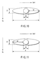
That is, the image of the combined laser beam L3 is formed, as shown in, for example, FIGS. 10 and 11, on the surface of the thermal recording medium 1 as a shape in which a circular beam profile Pf1 of the single mode laser beam L1 is superposed on an oblong beam profile Pf2 of the multimode laser beam L2. The forward and backward scanning directions of the combined laser beam L3 coincide with the oblong shape longitudinal directions of the beam profile Pf2 of the multimode laser beam L2 on the surface of the thermal recording medium 1. Incidentally, the combining position of the beam spot of the single mode laser beam L1 in the beam profile Pf2 of the multimode laser beam L2 is the central position in the main scanning direction (scanning direction) Sm as shown in FIGS. 10 and 11.
-
First, in the main scanning direction Sm1 of the forward travel, a forward travel head region k1 in the beam profile Pf2 of the multimode laser beam L2 included in the combined laser beam L3 is singly irradiated as shown in FIG. 10. The forward travel head region k1 is the region on the head side in the main scanning direction Sm1 of the forward travel of the combined laser beam L3. Although the temperature on the surface of the thermal recording medium 1 observed when the medium 1 is irradiated singly with the multimode laser beam L2 is equal to or lower than the color development temperature T2 as shown in FIG. 7, the thermal recording medium 1 is quickly heated up to the color disappearance temperature T1, and the temperature is raised.
-
Then, the surface of the thermal recording medium 1 is irradiated with superposition of the multimode laser beam L2 and the single mode laser beam L1 which are included in the combined laser beam L3. The thermal recording medium 1 is further heated quickly up to the color development temperature T2 from the state where the medium 1 is heated up to the color disappearance temperature T1, and hence the temperature on the surface of the thermal recording medium 1 is raised at this time. As a result of this, it becomes possible to record information on the thermal recording medium 1.
-
Then, the irradiation of the single mode laser beam L1 is terminated, and subsequently, when the irradiation of the multimode laser beam L2 is terminated, the printing layer of the thermal recording medium 1 is quickly cooled. As a result, a part of the printing layer of the thermal recording medium 1 irradiated singly with the multimode laser beam L2 is color-disappeared if there is a black part already color-developed. Further, a part of the printing layer of the thermal recording medium 1 that has been irradiated with the superposition of the multimode laser beam L2 and the single mode laser beam L1 is color-developed black.
-
Accordingly, by turning on/off the output of the single mode laser beam L1 in accordance with information such as a character, a mark, a pattern, and the like, it becomes possible to record information such as a character, a mark, a pattern, and the like on the thermal recording medium 1. The color to be developed on the thermal recording medium 1 is not limited to black, and an arbitrary color can be developed depending on the stain used.
-
Then, in the main scanning direction Sm2 of the backward travel, the backward travel head region k2 in the beam profile Pf2 of the multimode laser beam L2 included in the combined laser beam L3 is singly irradiated as shown in FIG. 11. The backward travel head region k2 is the region on the head side in the main scanning direction Sm2 of the backward travel of the combined laser beam L3. Although the temperature on the surface of the thermal recording medium 1 observed when the medium 1 is irradiated singly with the multimode laser beam L2 is equal to or lower than the color development temperature T2 as shown in FIG. 7, the thermal recording medium 1 is quickly heated up to the color disappearance temperature T1, and the temperature is raised.
-
Then, the surface of the thermal recording medium 1 is irradiated with superposition of the multimode laser beam L2 and the single mode laser beam L1 which are included in the combined laser beam L3. The thermal recording medium 1 is further heated quickly up to the color development temperature T2 from the state where the medium 1 is heated up to the color disappearance temperature T1, and hence the temperature on the surface of the thermal recording medium 1 is raised at this time. As a result of this, it becomes possible to record information on the thermal recording medium 1.
-
Then, the irradiation of the single mode laser beam L1 is terminated, and subsequently, when the irradiation of the multimode laser beam L2 is terminated, the printing layer of the thermal recording medium 1 is quickly cooled. As a result, a part of the printing layer of the thermal recording medium 1 irradiated singly with the multimode laser beam L2 is color-disappeared if there is a black part already color-developed. Further, a part of the printing layer of the thermal recording medium 1 that has been irradiated with the superposition of the multimode laser beam L2 and the single mode laser beam L1 is color-developed black.
-
Accordingly, by turning on/off the output of the single mode laser beam L1 in accordance with information such as a character, a mark, a pattern, and the like, it becomes possible to record information such as a character, a mark, a pattern, and the like on the thermal recording medium 1. The color to be developed on the thermal recording medium 1 is not limited to black, and an arbitrary color can be developed depending on the stain used.
-
As described above, according to the second embodiment, the single mode laser beam L1 output from the single mode semiconductor laser 2 and the multimode laser beam L2 output from the multimode semiconductor laser 3 are combined with each other by the polarization beam splitter 5, the combined laser beam L3 is used by the deflection scanning mechanism 20 to perform the main scanning on the surface of the thermal recording medium 1 in the main scanning direction Sm1 of the forward travel and in the main scanning direction Sm2 of the backward travel in a reciprocating manner.
-
As a result, the same advantage as the first embodiment can be obtained.
-
The combined laser beam L3 is used to perform the main scanning on the surface of the thermal recording medium 1 in the main scanning direction Sm1 of the forward travel and in the main scanning direction Sm2 of the backward travel in the same direction as the oblong shape longitudinal direction of the beam profile Pf2 of the multimode laser beam L2. As a result, it is possible to raise the temperature of the thermal recording medium 1 to the color disappearance region by the forward travel head region k1 in the main scanning direction Sm1 of the forward travel. Further, in the main scanning direction Sm2 of the backward travel too, it is possible to raise the temperature of the thermal recording medium 1 to the color disappearance region by the backward travel head region k2. As a result of this, the power of the multimode laser beam L2 can be effectively utilized. Furthermore, the combined laser beam L3 is used to perform the main scanning in the main scanning direction Sm1 of the forward travel and in the main scanning direction Sm2 of the backward travel in a reciprocating manner, and hence the speedup of recording of information on the entire surface of the thermal recording medium 1 can be more enhanced than in the first embodiment.
-
Next, a third embodiment of the present invention will be described below with reference to the accompanying drawings. Incidentally, the same parts as those shown in FIG. 1 are denoted by the same reference symbols, and a detailed description of them is omitted.
-
FIG. 12 shows a configuration view of a contactless optical writing apparatus. A plurality of single mode semiconductor lasers, for example, two single mode semiconductor lasers 2a and 2b are provided. Each of the single mode semiconductor lasers 2a and 2b is identical with the aforementioned single mode semiconductor laser 2. Each single mode semiconductor laser 2a or 2b outputs a single mode laser beam L1a or L1b of S-polarization to a polarization beam splitter 5. Each single mode semiconductor laser 2a or 2b is provided parallel with the polarization direction Sd1 of each single mode laser beam L1a or L1b of S-polarization output to the polarization beam splitter 5.
-
A plurality of multimode semiconductor lasers, for example, two multimode semiconductor lasers 3a and 3b are provided. Each multimode semiconductor laser 3a or 3b is identical with the aforementioned multimode semiconductor laser 3. Each multimode semiconductor laser 3a or 3b outputs a multimode laser beam L2a or L2b of P-polarization to the polarization beam splitter 5. Each multimode semiconductor laser 3a or 3b is provided perpendicular to the polarization direction Sd2 of each multimode laser beam L2a or L2b output therefrom. Incidentally, each multimode semiconductor laser 3a or 3b is provided on each mount 17a or 17b.
-
Next, the recording operation performed by the apparatus configured as described above will be described below.
-
Each single mode semiconductor laser 2a or 2b outputs a single mode laser beam L1a or L1b of S-polarization from each laser emitting section 13 to the polarization beam splitter 5.
-
Each single mode laser beam L1a or L1b is condensed into a substantially parallel light flux by a collimator lens 4, and is simultaneously made incident on the polarization beam splitter 5.
-
On the other hand, each multimode semiconductor laser 3a or 3b outputs a multimode laser beam L2a or L2b from each laser emitting section 15 to the polarization beam splitter 5. Each multimode laser beam L2a or L2b is condensed into a substantially parallel light flux by a collimator lens 9, and is simultaneously made incident on the polarization beam splitter 5.
-
The polarization beam splitter 5 reflects each single mode laser beam L1a or L1b, at the same time, transmits each multimode laser beam L2a or L2b, combines each single mode laser beam L1a or L1b and each multimode laser beam L2a or L2b with each other, and outputs each combined laser beam L3a or L3b. Each combined laser beam L3a or L3b is made incident on a deflection scanning mechanism 7.
-
The deflection scanning mechanism 7 continuously rotates a polygon mirror 10 in the arrow direction f. As a result, the deflection scanning mechanism 7 performs the main scanning on the thermal recording medium 1 in the main scanning direction Sm using each combined laser beam L3a or L3b output from the polarization beam splitter 5. In this case, a rotating shaft 11 of the polygon mirror 10 is provided parallel with the polarization direction Sd1 of each single mode laser beam L1a or L1b, and perpendicular to the polarization direction Sd2 or Sd2 of each multimode laser beam L2a or L2b.
-
However, each combined laser beam L3a or L3b is used by the deflection scanning mechanism 7 to perform the main scanning in the same direction as the polarization direction Sd2 or Sd2 of each multimode laser beam L2a or L2b.
-
An image of each combined laser beam L3a or L3b is formed on the surface of the thermal recording medium 1 by a scanning lens 8.
-
Each combined laser beam L3a or L3b is used to synchronously perform the main scanning on the thermal recording medium 1 in the same direction as each oblong shape direction of each multimode laser beam L2a or L2b formed into each oblong beam profile Pf2 or Pf2. The main scanning directions Sm and Sm of the respective combined laser beams L3a and L3b are parallel with each other.
-
An image of each combined laser beam L3a or L3b is formed on the surface of the thermal recording medium 1 as a form in which each circular beam profile Pf1 of each single mode laser beam L1a or L1b is superposed on each oblong beam profile Pf2 of each multimode laser beam L2a or L2b as shown in, for example, FIG. 4 or 5. The combining position of a beam spot of each single mode laser beam L1a or L1b in each beam profile Pf2 or Pf2 of each multimode laser beam L2a or L2b is in the beam profile Pf2 of each multimode laser beam L2a or L2b and in the rear part thereof in the main scanning direction Sm as shown in, for example, FIG. 4. Alternatively, the combining position of a beam spot of each single mode laser beam L1a or L1b in each beam profile Pf2 or Pf2 of each multimode laser beam L2a or L2b is in the beam profile Pf2 of each multimode laser beam L2a or L2b and in the center thereof in main scanning direction Sm as shown in, for example, FIG. 5.
-
When the surface of the thermal recording medium 1 is scanned by using each multimode laser beam L2a or L2b, first, as described above, the surface of the thermal recording medium 1 is irradiated singly with each multimode laser beam L2a or L2b. Then, the surface of the thermal recording medium 1 is irradiated with superposition of each multimode laser beam L2a or L2b and each single mode laser beam L1a or L1b. Then, the irradiation of each single mode laser beam L1a or L1b is terminated, and subsequently, the irradiation of each multimode laser beam L2a or L2b is terminated. As a result, it is possible to record information such as an image at a part that has been irradiated with the superposition of each multimode laser beam L2a or L2b and each single mode laser beam L1a or L1b. As a result of this, it becomes possible to record information such as a character, a mark, a pattern, and the like on the thermal recording medium 1 simultaneously in two lines.
-
As described above, according to the third embodiment, for example, two single mode semiconductor lasers 2a and 2b are provided, further, for example, two multimode semiconductor lasers 3a and 3b are provided, and the main scanning is performed on the thermal recording medium 1 by the polygon mirror 10 using each combined laser beam L3a or L3b. As a result, it is possible to obtain the same advantage as the first embodiment, perform the main scanning on the surface of the thermal recording medium 1 by using the respective combined laser beams L3a and L3b in parallel with the main scanning direction Sm and simultaneously, and record information such as a character, a mark, a pattern, and the like simultaneously in two lines.
-
Next, a fourth embodiment of the present invention will be described below with reference to the accompanying drawings. Incidentally, the same parts as those shown in FIG. 12 are denoted by the same reference symbols, and a detailed description of them is omitted.
-
FIG. 13 shows a configuration view of a contactless optical writing apparatus. A deflection scanning mechanism 20 is identical with the deflection scanning mechanism 20 in the second embodiment. The deflection scanning mechanism 20 includes a galvano-mirror 21, and a rotary drive section 23. The deflection scanning mechanism 20 performs main scanning on a thermal recording medium 1 in the main scanning direction Sm1 of the forward travel and in the main scanning direction Sm2 of the backward travel in a reciprocating manner by using each combined laser beam L3a or L3b output from a polarization beam splitter 5 by a repeatedly reciprocating swing of the galvano-mirror 21 in the arrow directions g.
-
A rotating shaft 22 of the galvano-mirror 21 is provided parallel with each polarization direction Sd1 or Sd1 of each single mode laser beam L1a or L1b with respect to the polarization beam splitter 5, and perpendicular to each polarization direction Sd2 or Sd2 of each multimode laser beam L2a or L2b with respect to the polarization beam splitter 5. As a result, the deflection scanning mechanism 20 performs the main scanning in the main scanning direction Sm1 of the forward travel, and in the main scanning direction Sm2 of the backward travel by using each combined laser beam L3a or L3b in the same direction as each polarization direction Sd2 or Sd2 of each multimode laser beam L2a or L2b.
-
Next, the recording operation performed by the apparatus configured as described above will be described below.
-
Each single mode semiconductor laser 2a or 2b outputs a single mode laser beam L1a or L1b of S-polarization to the polarization beam splitter 5. Each single mode laser beam L1a or L1b is condensed into a substantially parallel light flux by a collimator lens 4, and is simultaneously made incident on the polarization beam splitter 5.
-
On the other hand, each multimode semiconductor laser 3a or 3b outputs a multimode laser beam L2a or L2b of P-polarization to the polarization beam splitter 5. Each multimode laser beam L2a or L2b is condensed into a substantially parallel light flux by a collimator lens 9, and is simultaneously made incident on the polarization beam splitter 5.
-
The polarization beam splitter 5 reflects each single mode laser beam L1a or L1b, transmits each multimode laser beam L2a or L2b, combines each single mode laser beam L1a or L1b and each multimode laser beam L2a or L2b with each other, and outputs each combined laser beam L3a or L3b. Each combined laser beam L3a or L3b is made incident on the deflection scanning mechanism 20.
-
The deflection scanning mechanism 20 repeatedly swings the galvano-mirror 21 in the arrow directions g by the drive of the rotary drive section 23 through a rotating shaft 22. As a result, each combined laser beam L3a or L3b output from the polarization beam splitter 5 is used for the main scanning performed on the thermal recording medium 1 in the main scanning direction Sm1 of the forward travel and in the main scanning direction Sm2 of the backward travel in a reciprocating manner. An image of the combined laser beam L3a or L3b used by the deflection scanning mechanism 20 for the main scanning performed in a reciprocating manner is formed on the surface of the thermal recording medium 1 by a scanning lens 8.
-
That is, the image of the combined laser beam L3a or L3b is formed on the surface of the thermal recording medium 1 as a form in which a beam profile Pf1 of each single mode laser beam L1a or L1b is superposed on a beam profile Pf2 of each multimode laser beam L2a or L2b in the same manner as shown in, for example, FIGS. 10 and 11. The forward and backward scanning directions of the combined laser beam L3a or L3b coincide with the oblong shape longitudinal directions of the beam profile Pf2 of each multimode laser beam L2a or L2b on the surface of the thermal recording medium 1.
-
Incidentally, the combining position of the beam spot of each single mode laser beam L1a or L1b in the beam profile Pf2 of each multimode laser beam L2a or L2b is in the center thereof in the main scanning direction (scanning direction) on the thermal recording medium 1 as in the case shown in FIGS. 10 and 11.
-
First, the surface of the thermal recording medium 1 is irradiated singly with each multimode laser beam L2a or L2b. Then, the surface of the thermal recording medium 1 is irradiated with superposition of each multimode laser beam L2a or L2b and each single mode laser beam L1a or L1b. Then, the irradiation of each single mode laser beam L1a or L1b is terminated, and subsequently, the irradiation of each multimode laser beam L2a or L2b is terminated. As a result, as in the case described previously, information such as an image can be recorded on a part that has been irradiated with the superposition of each multimode laser beam L2a or L2b and each single mode laser beam L1a or L1b.
-
Then, in the main scanning direction Sm2 of the backward travel, the surface of the thermal recording medium 1 is irradiated singly with each multimode laser beam L2a or L2b. Then, the surface of the thermal recording medium 1 is irradiated with superposition of each multimode laser beam L2a or L2b and each single mode laser beam L1a or L1b. Then, the irradiation of each single mode laser beam L1a or L1b is terminated, and subsequently, the irradiation of each multimode laser beam L2a or L2b is terminated. As a result, as in the case described previously, information such as an image can be recorded on a part that has been irradiated with the superposition of each multimode laser beam L2a or L2b and each single mode laser beam L1a or L1b.
-
As a result of this, it becomes possible to record information such as a character, a mark, a pattern, and the like on the thermal recording medium 1 simultaneously in two lines.
-
As described above, according to the fourth embodiment, a plurality of single mode semiconductor lasers 2, for example, two single mode semiconductor lasers 2a and 2b are provided, further a plurality of multimode semiconductor lasers 3, for example, two multimode semiconductor lasers 3a and 3b are provided, the main scanning is performed on the thermal recording medium 1 using the combined laser beams L3a and L3b in the main scanning direction Sm1 of the forward travel and in the main scanning direction Sm2 of the backward travel simultaneously and in a reciprocating manner by means of the galvano-mirror 21. As a result, it is possible to obtain the same advantage as the first embodiment, perform the main scanning on the thermal recording medium 1 by simultaneously using the respective combined laser beams L3a and L3b in parallel with the main scanning direction Sm, and record information such as a character, a mark, a pattern, and the like simultaneously in two lines.
-
Next, a fifth embodiment of the present invention will be described below with reference to the accompanying drawings. Incidentally, the same parts as those shown in FIG. 9 are denoted by the same reference symbols, and a detailed description of them is omitted.
-
FIG. 14 shows a configuration view of a contactless optical writing apparatus. In the apparatus, the arrangement positions of the single mode semiconductor laser 2 and the multimode semiconductor laser 3 are replaced with each other, and the polarization direction Sd1 of the single mode laser beam L1 and the polarization direction Sd2 of the multimode laser beam L2 are also set to be replaced with each other. In accordance with the replacement of the arrangement positions of the single mode semiconductor laser 2 and the multimode semiconductor laser 3, the arrangement positions of the collimator lens 4 and the collimator lens 9 are also replaced with each other.
-
The junction plane direction of the pn junction plane in the single mode semiconductor laser 2 is arranged perpendicular to the direction of the rotating shaft 22 of the galvano-mirror 21. The polarization direction Sd1 of the single mode laser beam L1 output from the single mode semiconductor laser 2 is the same as the junction plane direction of the pn junction plane 14. As a result, the polarization direction Sd1 of the single mode laser beam L1 is perpendicular to the rotating shaft 22 of the galvano-mirror 21. The single mode laser beam L1 output from a laser emitting section 13 of the single mode semiconductor laser 2 is of P-polarization with respect to the polarization beam splitter 5.
-
The junction plane direction of the pn junction plane 16 in the multimode semiconductor laser 3 is arranged parallel with the direction of the rotating shaft 22 of the galvano-mirror 21. The polarization direction Sd2 of the multimode laser beam L2 output from the multimode semiconductor laser 3 is the same as the junction plane direction of the pn junction plane 16. As a result, the polarization direction Sd2 of the multimode laser beam L2 is parallel with the rotation shaft 22 of the galvano-mirror 21. The multimode laser beam L2 output from the multimode semiconductor laser 3 is of S-polarization with respect to the polarization beam splitter 5.
-
The polarization beam splitter 5 reflects the multimode laser beam L2 output from the multimode semiconductor laser 3, transmits the single mode laser beam L1 output from the single mode semiconductor laser 2, and outputs a combined laser beam L3 obtained by combining the multimode laser beam L2 and the single mode laser beam L1 with each other.
-
A beam spot position varying mechanism 18 moves the polarization beam splitter 5 in the traveling direction h of the single mode laser beam L1, or rotates the polarization beam splitter 5 around a rotating axis parallel with the vibration direction of the S-polarization. As a result, the beam spot position varying mechanism 18 varies the combining position of the single mode laser beam L1 in the beam profile Pf2 of the multimode laser beam L2 on the thermal recording medium 1.
-
FIGS. 15 and 16 each show the combining position of the single mode laser beam L1 in the oblong beam profile Pf2 of the multimode laser beam L2 on the thermal recording medium 1. FIG. 15 shows that the single mode laser beam L1 having a circular beam profile Pf1 is combined with the multimode laser beam L2 at a position in the oblong beam profile Pf2 of the multimode laser beam L2 and in the center thereof in the main scanning direction Sm. FIG. 16 shows that the single mode laser beam L1 having the circular beam profile Pf1 is combined with the multimode laser beam L2 at a position in the oblong beam profile Pf2 of the multimode laser beam L2 and on the rear side thereof in the sub-scanning direction Ss.
-
Next, the recording operation performed by the apparatus configured as described above will be described below.
-
The single mode semiconductor laser 2 outputs a single mode laser beam L1. At the same time, the multimode semiconductor laser 3 outputs a multimode laser beam L2. The polarization beam splitter 5 reflects the multimode laser beam L2 output from the multimode semiconductor laser 3, transmits the single mode laser beam L1 output from the single mode semiconductor laser 2, and outputs a combined laser beam L3 obtained by combining the multimode laser beam L2 and the single mode laser beam L1 with each other.
-
A deflection scanning mechanism 20 performs the main scanning on the thermal recording medium 1 in the main scanning direction Sm1 of the forward travel, and in the main scanning direction Sm2 of the backward travel by using the combined laser beam L3 in a reciprocating manner by repeatedly swinging the galvano-mirror 21 in the arrow directions g in a reciprocating manner. In this case, in the multimode semiconductor laser 3, the laser emitting section 15 is long in the direction parallel with the pn junction plane 16, and hence it is difficult to condense the multimode laser beam L2. Thus, multimode laser beam L2 is formed into an oblong beam profile Pf2 on the thermal recording medium 1. The oblong shape longitudinal direction of the oblong beam profile Pf2 of the multimode laser beam L2 coincides with the sub-scanning direction Ss on the thermal recording medium 1.
-
However, the deflection scanning mechanism 20 performs the main scanning in the main scanning direction Sm1 of the forward travel, and in the main scanning direction Sm2 of the backward travel in a reciprocating manner by using the combined laser beam L3. A transfer mechanism 19 transfers the thermal recording medium 1 in the sub-scanning direction at, for example, a constant transfer speed. As a result of this, information such as a character, a mark, a pattern, and the like is recorded on the entire surface of the thermal recording medium 1. The scanning direction of the sub-scanning direction Ss is identical with the upright shape longitudinal direction of the beam profile Pf2 of the multimode laser beam L2 included in the combined laser beam L3. Incidentally, it is represented that the beam profile Pf2 of the multimode laser beam L2 is 'upright' or 'oblong' with respect to the main scanning direction Sm1 or Sm2 of the combined laser beam L3.
-
As described above, according to the fifth embodiment, the arrangement positions of the single mode semiconductor laser 2 and the multimode semiconductor laser 3 are replaced with each other, and the polarization direction Sd1 of the single mode laser beam L1 and the polarization direction Sd2 of the multimode laser beam L2 are set to be replaced with each other. As a result of this, it is possible to obtain the same advantage as the first embodiment. Further, the combined laser beam L3 is used to perform the main scanning in the main scanning direction Sm1 of the forward travel, and in the main scanning direction Sm2 of the backward travel in a reciprocating manner, and hence the speedup of recording of information on the entire surface of the thermal recording medium 1 can be more enhanced than in the first embodiment.
-
Next, a sixth embodiment of the present invention will be described below with reference to the accompanying drawings. Incidentally, the same parts as those shown in FIG. 1 are denoted by the same reference symbols, and a detailed description of them is omitted.
-
FIG. 17 shows a configuration view of a contactless optical writing apparatus. A deflection scanning mechanism 30 includes a polygon mirror 10, and a rotary drive section 12. The rotary drive section 12 is coupled to the polygon mirror 10 through a rotating shaft 11, and rotates the polygon mirror 10 in one direction, e.g., in the arrow direction u. The rotating shaft 11 of the polygon mirror 10 is provided at a position obtained by rotating the direction of the rotating shaft of the rotary drive section 12 in the first embodiment by an angle of, for example, 90° around the traveling direction of the combined laser beam L3 output from the polarization beam splitter 5. As a result, the single mode semiconductor laser 2 is arranged in such a direction that the junction plane direction of the pn junction plane 14 of the laser emitting section 13 is perpendicular to the rotating shaft 11 of the polygon mirror 10. The multimode semiconductor laser 3 is arranged in such a manner that the junction plane direction of the pn junction plane 16 of the laser emitting region is parallel with the rotating shaft 11 of the polygon mirror 10.
-
The deflection scanning mechanism 30 performs the main scanning on the thermal recording medium 1 by using the combined laser beam L3 output from the polarization beam splitter 5 by the rotation of the polygon mirror 10 in the arrow direction u. Incidentally, the main scanning direction Sm of the deflection scanning mechanism 30 is obtained by rotating the main scanning direction Sm of the deflection scanning mechanism 7 in the first embodiment by, for example, 90°. The multimode semiconductor laser 3 is set in such a direction that the polarization direction Sd2 of the multimode laser beam L2 is parallel with the direction of the rotating shaft 11 of the polygon mirror 10. As a result of this, the deflection scanning mechanism 30 performs the main scanning by using the combined laser beam L3 in the rotating direction for example, 90° as the polarization direction Sd2 of the multimode laser beam L2.
-
A scanning lens 8 forms an image of the combined laser beam L3 used by the deflection scanning mechanism 30 for the main scanning on the surface of the thermal recording medium 1. That is, the single mode laser beam L1 and the multimode laser beam L2 included in the combined laser beam L3 are respectively condensed by the scanning lens 8. As a result, the image of the combined laser beam L3 is formed on the thermal recording medium 1. The single mode laser beam L1 included in the combined laser beam L3 is formed as a circular beam profile Pf1 on the thermal recording medium 1. The multimode laser beam L2 is formed as an upright beam profile Pf2 on the thermal recording medium 1.
-
A transfer mechanism 31 transfers the thermal recording medium 1 in the same direction as the sub-scanning direction Ss perpendicular to the main scanning direction Sm at, for example, a constant transfer speed.
-
Next, the recording operation performed by the apparatus configured as described above will be described below as to the point different from the first embodiment.
-
The deflection scanning mechanism 30 continuously rotates the polygon mirror 10 in the arrow direction u. As a result, the combined laser beam L3 output from the polarization beam splitter 5 is used to perform the main scanning in the main scanning direction Sm on the thermal recording medium 1. Incidentally, the main scanning direction Sm of the combined laser beam L3 is obtained by rotating the main scanning direction Sm of the deflection scanning mechanism 7 in the first embodiment by, for example, 90°.
-
The scanning lens 8 forms the image of the combined laser beam L3 used by the deflection scanning mechanism 30 for the main scanning on the surface of the thermal recording medium 1. As a result, the image of the combined laser beam L3 is formed on the thermal recording medium 1. The single mode laser beam L1 included in the combined laser beam L3 is formed as a circular beam profile Pf1 on the thermal recording medium 1. The multimode laser beam L2 is formed as an upright beam profile Pf2 on the thermal recording medium 1.
-
At this time, the thermal recording medium 1 is transferred by the transfer mechanism 31 in the same direction as the sub-scanning direction Ss perpendicular to the main scanning direction Sm of the combined laser beam L3 at, for example, a constant transfer speed.
-
When the surface of the thermal recording medium 1 is scanned by using the combined laser beam L3, as in the case described above, first, the surface of the thermal recording medium 1 is irradiated singly with the multimode laser beam L2. Then, the surface of the thermal recording medium 1 is irradiated with superposition of the multimode laser beam L2 and the single mode laser beam L1. Then, the irradiation of the single mode laser beam L1 is terminated, and subsequently, the irradiation of the multimode laser beam L2 is terminated. As a result, information such as an image can be recorded on a part that has been irradiated with the superposition of the multimode laser beam L2 and the single mode laser beam L1. As a result of this, it becomes possible to record information such as a character, a mark, a pattern, and the like on the thermal recording medium 1.
-
As described above, according to the sixth embodiment, the rotating shaft 11 of the polygon mirror 10 is provided at a position obtained by rotating the direction of the rotating shaft 11 of the rotary drive section 12 in the first embodiment around the traveling direction of the combined laser beam L3 by an angle of, for example, 90°. As a result of this too, the sixth embodiment can obtain the same advantage as the first embodiment.
-
Next, a seventh embodiment of the present invention will be described below with reference to the accompanying drawings. Incidentally, the same parts as those shown in FIG. 1 are denoted by the same reference symbols, and a detailed description of them is omitted.
-
FIG. 18 shows a configuration view of a contactless optical writing apparatus. The apparatus comprises a single mode semiconductor laser 2 which is a first semiconductor laser serving as a light source for emitting a laser beam, a multimode semiconductor laser 3 which is a second semiconductor laser, a single mode semiconductor laser 40 which is a third semiconductor laser, and a single mode semiconductor laser 41 which is a fourth semiconductor laser.
-
Of these lasers, the single mode semiconductor laser 2 outputs a single mode laser beam L1 having a wavelength of, for example, λ1 (=808 nm). The multimode semiconductor laser 3 outputs a multimode laser beam L2 having a wavelength of, for example, λ1 (=808 nm).
-
The single mode semiconductor lasers 40 and 41 respectively outputs single mode laser beams L3 and L4 having wavelengths λ2 and λ3 in the near-infrared region. More specifically, the single mode semiconductor laser 40 outputs a single mode laser beam L3 having an emission wavelength of, for example, λ2 (=980 nm). The single mode semiconductor laser 41 outputs a single mode laser beam L4 having an emission wavelength of, for example, λ3 (=900 nm).
-
A collimator lens 42, a polarization beam splitter 43, a deflection scanning mechanism 20, and a scanning lens 8 are provided between the single mode semiconductor laser 2 and a thermal recording medium 1 along a laser light irradiation path.
-
A collimator lens 44, a dichroic prism 45 serving as a color composition element, a polarization beam splitter 45 serving as a color composition element, the deflection scanning mechanism 20, and the scanning lens 8 are provided between the single mode semiconductor laser 40 and the thermal recording medium 1 along the laser light irradiation path.
-
A collimator lens 46, two dichroic prisms 47 and 45 each serving as a color composition element, the polarization beam splitter 43, the deflection scanning mechanism 20, and the scanning lens 8 are provided between the single mode semiconductor laser 41 and the thermal recording medium 1 along the laser light irradiation path.
-
A collimator lens 48, the two dichroic prisms 47 and 45, the polarization beam splitter 43, the deflection scanning mechanism 20, and the scanning lens 8 are provided between the multimode semiconductor laser 3 and the thermal recording medium 1 along the laser light irradiation path.
-
The deflection scanning mechanism 20 includes a galvano-mirror 21 serving as a deflecting member, and a rotary drive section 23. The galvano-mirror 21 is coupled to the rotary drive section 23 through a rotating shaft 22. The rotary drive section 23 causes the galvano-mirror 21 to perform reciprocating motion in the arrow directions g through the rotating shaft 22.
-
The single mode semiconductor laser 2 has a pn junction plane (junction plane of active layers) 4 in the laser emitting section 13 thereof as in the case shown in FIG. 2. The single mode semiconductor laser 2 is arranged in such a manner that the junction plane direction of the pn junction plane 14 of the laser emitting section 13 is parallel with the rotating shaft 22 of the galvano-mirror 21. The polarization direction Sd1 of the single mode laser beam L1 is identical with the junction plane direction of the pm junction plane 14. As a result, the polarization direction of the single mode laser beam L1 becomes perpendicular to the polarization beam splitter 43. Accordingly, the single mode laser beam L1 emitted from the laser emitting section 13 of the single mode semiconductor laser 2 is of S-polarization. The light emitting region in the laser emitting section 13 is the same as that shown in FIG. 2, and hence a description thereof is omitted.
-
The multimode semiconductor laser 3 includes a pn junction plane 16 in the laser emitting section 15 thereof as in the case shown in FIG. 3. The multimode semiconductor laser 3 is so arranged as to allow the junction plane direction of the pn junction plane 16 of the light emitting region to be perpendicular to the rotating shaft 22 of the galvano-mirror 21. The polarization direction Sd2 of the multimode laser beam L2 is the same as the junction plane direction of the pn junction plane 16. As a result, the multimode laser beam L2 emitted from the light emitting region of the multimode semiconductor laser 3 is of P-polarization. The light emitting region in the laser emitting section 15 is the same as that shown in FIG. 3, and hence a description thereof is omitted.
-
Each single mode semiconductor laser 40 or 41 has a laser emitting section 13 in which a pn junction plane 14 is formed. Each single mode semiconductor laser 40 or 41 is arranged such that the junction plane direction of the pn junction plane 14 of the laser emitting section 13 is perpendicular to the rotating shaft 22 of the galvano-mirror 21.
-
Each polarization direction Sd3 or Sd4 of each single mode laser beam L3 or L4 is the same direction as the junction plane direction of the pn junction plane 14. However, each polarization direction Sd3 or Sd4 of each single mode laser beam L3 or L4 is in the horizontal direction with respect to the polarization beam splitter 43. As a result, each single mode laser beam L3 or L4 is of P-polarization. Incidentally, each single mode laser beam L3 or L4 emitted from each laser emitting section 13 of each single mode semiconductor laser 40 or 41 spreads with a profile Pf3 or Pf4 as it advances as shown in FIG. 18. Each beam profile Pf3 or Pf4 has a Gaussian distribution.
-
A size of the light emitting region in each laser emitting section 13 of each single mode semiconductor laser 40 or 41 is, as in the case of the single mode semiconductor laser 2 shown in FIG. 2, about several µm in, for example, the junction plane direction a1 of the pn junction plane 14 and in the direction b1 perpendicular to the junction plane direction a1. More specifically, as for the size of the light emitting region of the laser emitting section 13, for example, a1 in the junction plane direction is about 3 µm, and b1 in the direction perpendicular to the junction plane direction is about 1 µm.
-
The first collimator lens 42 is provided on the progression optical path of the single mode laser beam L1 output from the single mode semiconductor laser 2. The first collimator lens 42 condenses the single mode laser beam L1 output from the single mode semiconductor laser 2 into a substantially parallel light flux.
-
The second collimator lens 48 is provided on the progression optical path of the multimode laser beam L2 output from the multimode semiconductor laser 3. The second collimator lens 48 condenses the multimode laser beam L2 output from the multimode semiconductor laser 3 into a substantially parallel light flux.
-
The third collimator lens 44 is provided on the progression optical path of the single mode laser beam L3 output from the single mode semiconductor laser 40. The third collimator lens 44 condenses the single mode laser beam L3 output from the single mode semiconductor laser 40 into a substantially parallel light flux.
-
The fourth collimator lens 46 is provided on the progression optical path of the single mode laser beam L4 output from the single mode semiconductor laser 41. The fourth collimator lens 46 condenses the single mode laser beam L4 output from the single mode semiconductor laser 41 into a substantially parallel light flux.
-
The two dichroic prisms 47 and 45 each serving as a superposition optical system are provided on the progression optical path of the multimode laser beam L2 output from the multimode semiconductor laser 3.
FIG. 19 shows reflectance versus wavelength characteristics of the dichroic prisms 47 and 45. The dichroic prism 47 has a characteristic 14a in which the reflectance is high only in a region including a wavelength λ3 (=900 nm). The dichroic prism 47 is provided at an intersection position at which the progression optical path of the multimode laser beam L2 and the progression optical path of the single mode laser beam L4 output from the single mode semiconductor laser 41 intersect each other. The dichroic prism 47 transmits the multimode laser beam L2 having a wavelength λ1 (=808 nm) and output from the multimode semiconductor laser 3, changes the direction of the single mode laser beam L4 having a wavelength λ3 (=900 nm) and output from the single mode semiconductor laser 41 by 90°, reflects the resultant single mode laser beam L4, and outputs a laser beam La formed by superposing the single mode laser beam L4 on the multimode laser beam L2.
-
The dichroic prism 45 has a characteristic 15a in which the reflectance is high only in a region including a wavelength λ2 (=980 nm). The dichroic prism 45 is provided at an intersection position at which the progression optical path of the superposed laser beam La output from the dichroic prism 47 and the progression optical path of the single mode laser beam L3 output from the single mode semiconductor laser 40 intersect each other.
-
The dichroic prism 45 transmits the superposed laser beam La having wavelengths λ1 and λ3 and output from the dichroic prism 47. At the same time, the dichroic prism 45 changes the direction of the single mode laser beam L3 having a wavelength λ2 (=980 nm) and output from the single mode semiconductor laser 40 by 90°, and reflects the resultant single mode laser beam L3. As a result of this, the dichroic prism 45 outputs a laser beam Lb formed by superposing the single mode laser beam L3 on the superposed laser beam La.
-
The polarization beam splitter 43 is provided at an intersection position at which at which the progression optical path of the single mode laser beam L1 output from the single mode semiconductor laser 2 and the progression optical path of the superposed laser beam Lb output from the dichroic prism 45 intersect each other. The single mode laser beam L1 output from the single mode semiconductor laser 2 and the superposed laser beam Lb output from the dichroic prism 45 are made incident on the polarization beam splitter 43. The polarization beam splitter 43 changes the direction of the single mode laser beam L1 which is output from the single mode semiconductor laser 2, and is of S-polarization by 90°, and reflects the resultant single mode laser beam L1. At the same time, the polarization beam splitter 43 transmits the superposed laser beam Lb output from the dichroic prism 45. As a result of this, the polarization beam splitter 43 combines the single mode laser beam L1 and the superposed laser beam Lb with each other, and outputs the resultant combined laser beam. Incidentally, the superposed laser beam Lb is formed by superposing the multimode laser beam L2 which is of P-polarization with respect to the polarization beam splitter 43, and the single mode laser beams L3 and L4 which are of S-polarization with respect to the polarization beam splitter 43 upon one another.
-
The deflection scanning mechanism 20 scans the thermal recording medium 1 in the main scanning directions Sm1 and Sm2 in a reciprocating manner by using the combined laser beam Lc output from the polarization beam splitter 43 by the reciprocating motion of the galvano-mirror 21 in the arrow directions g. The multimode semiconductor laser 3 is set in such a direction that the polarization direction Sd2 of the P-polarization of the multimode laser beam L2 is perpendicular to the rotating shaft 22 of the galvano-mirror 21. As a result, the deflection scanning mechanism 20 performs the main scanning in a reciprocating manner by using the combined laser beam Lc in the main scanning direction Sm1 and the main scanning direction Sm2 which coincide with the polarization direction Sd2 of the multimode laser beam L2.
-
The multimode semiconductor laser 3 is arranged in such a manner that the junction plane direction of the pn junction plane 16 of the laser emitting section 15 is parallel to the main scanning directions Sm1 and Sm2 of the combined laser beam Lc used by the deflection scanning mechanism 20 in the scanning. The single mode semiconductor laser 2 is arranged in such a manner that the junction plane direction of the pn junction plane 14 is perpendicular to the junction plane direction of the pn junction plane 16 of the multimode semiconductor laser 3.
-
On the other hand, each single mode semiconductor laser 40 or 41 is arranged in such a manner that the junction plane direction of the pn junction plane 14 of the laser emitting section 13 is horizontal with respect to the main scanning directions Sm1 and Sm2 of the combined laser beam Lc used by the deflection scanning mechanism 20 in the scanning.
-
The scanning lens 8 is provided in the main scanning directions Sm1 and Sm2 of the combined laser beam Lc used by the deflection scanning mechanism 20. The scanning lens 8 forms an image of the combined laser beam Lc used by the deflection scanning mechanism 20 for the main scanning on the surface of the thermal recording medium 1.
-
FIG. 20 shows a beam profile of the combined laser beam Lc formed on the thermal recording medium 1. The combined laser beam Lc includes the laser beam L1 having a circular beam profile Pf1, the laser beam L2 having an oblong beam profile Pf2, the laser beam L3 having a circular beam profile Pf3, and the laser beam L4 having a circular beam profile Pf4. The laser beams L1, L3, and L4 are each superposed on the oblong beam profile Pf2. The position at which each of the laser beams L1, L3, and L4 is superposed on the beam profile Pf2 is, for example, approximately the center of the oblong beam profile Pf2 of the laser beam L2.
-
The laser emitting section 13 of each of the single mode semiconductor lasers 2, 40, and 41 has a length of only about several µm in each direction parallel to or perpendicular to the pn junction plane 14. Accordingly, it is easy to form each of the beam profiles Pf1, Pf3, and Pf4 into a substantially circular shape by condensing each beam profile by means of the scanning lens 8.
-
Each of the single mode laser beams L1, L3, and L4 can be condensed into, for example, a substantially circular shape of about 100 µm (1/e2). On the other hand, as for the shape/size of the laser emitting section 15 of the multimode semiconductor laser 3, the length thereof in the direction parallel to the pn junction plane 16 is longer than that in the direction perpendicular to the pn junction plane 16 and, furthermore, is about 50 to 200 µm. As a result, it is difficult to condense the multimode laser beam L2 into a substantially circular shape of the beam profile Pf2 by means of the scanning lens 8. The multimode laser beam L2 has an oblong shape elongated in the direction of the pn junction plane 16.
-
Accordingly, images of the multimode laser beam L2 and the single mode laser beams L1, L3, and L4 are formed on the surface of the thermal recording medium 1 as a form in which the substantially circular beam profiles Pf1, Pf3, and Pf4 are superposed on the oblong beam profile Pf2.
-
The deflection scanning mechanism 20 performs the main scanning by using the combined laser beam Lc in the same direction as the polarization direction Sd2 of the multimode laser beam L2. As a result, the oblong shape longitudinal direction of the beam profile Pf2 of the multimode laser beam L2 coincides with the main scanning direction Sm1 and the main scanning direction Sm2 on the thermal recording medium 1. Incidentally, each of the single mode laser beams L1, L3, and L4 is combined with the multimode laser beam L2 at a position in the oblong beam profile Pf2 of the multimode laser beam L2 and in the center thereof. Incidentally, although the combining positions of the respective single mode laser beams L1, L3, and L4 are made to coincide with each other, the combining positions are shifted from one another on the drawing for easy understanding of the superposition of the respective single mode laser beams L1, L3, and L4.
-
The center (peak of power) of each of the single mode laser beams L1, L3, and L4 coincides with the center (peak of power) of the multimode laser beam L2. As long as the combined laser beam is a combination of such single mode laser beams L1, L3, and L4, and such a multimode laser beam L2, it is possible to improve the utilization efficiency of energy by causing the instantaneous power peaks of the respective single mode laser beam L1, L3, and L4 and the instantaneous power peak of the multimode laser beam L2 to coincide with one another. The combining position of each of the single mode laser beams L1, L3, and L4 in the beam profile Pf2 of the multimode laser beam L2 is not limited to the center of the beam profile Pf2, and may be varied depending on the recording conditions or environmental conditions.
-
Each of the substantially circular beam profiles Pf1, Pf3, and Pf4 used in the scanning of the thermal recording medium 1 is formed into a shape in which both a beam diameter c1 in the vertical direction and a beam diameter c2 in the lateral direction are, for example, about 100 µm as shown in FIG. 20. The oblong beam profile Pf2 is formed into a shape in which a beam length c1 in the vertical direction is, for example, about 100 µm, and a beam length d in the lateral direction is, for example, a little over 1 mm.
-
FIG. 21 shows a relationship between the temperature on the thermal recording medium 1 and color development/color disappearance obtained when the thermal recording medium 1 is irradiated with the single mode laser beam L1, multimode laser beam L2, or combined laser beam Lc. The single mode laser beam L1 has only output power capable of heating the printing layer of the thermal recording medium 1 up to a temperature equal to or lower than the color disappearance temperature T1 when the thermal recording medium 1 is irradiated singly with the single mode laser beam L1. As a result, the thermal recording medium 1 does not develop a color.
-
On the other hand, the multimode laser beam L2 has output power capable of heating the printing layer of the thermal recording medium 1 up to the color disappearance temperature T1, although the temperature T1 is lower than the color development temperature T2, when the thermal recording medium 1 is irradiated singly with the multimode laser beam L2. As a result, the temperature rise obtained when the thermal recording medium is irradiated singly with the multimode laser beam L2 is equal to or higher than the color disappearance temperature T1 and equal to or lower than the color development temperature T2, and the temperature of the thermal recording medium 1 is raised to the color disappearance region in which the developed color of the thermal recording medium 1 can be disappeared.
-
Then, when the thermal recording medium 1 is irradiated with the combined laser beam Lc formed by combining each of the single mode laser beams L1, L3, and L4 and the multimode laser beam L2 with one another, the printing layer of the thermal recording medium 1 is further heated quickly from a state where it is heated up to the color disappearance temperature T1 to the color development temperature T2. As a result, by irradiating the thermal recording medium 1 with the combined laser beam Lc, it is made possible to raise the temperature of the thermal recording medium 1 to a temperature equal to or higher than the color development temperature T2, and record information on the thermal recording medium 1. That is, combing each of the single mode laser beams L1, L3, and L4 with the multimode laser beam L2 enhances the recording power level.
-
Next, the recording operation performed by the apparatus configured as described above will be described below.
-
The single mode semiconductor laser 2 outputs a single mode laser beam L1 having a wavelength λ1 (=808 nm) from the laser emitting section 13. The single mode laser beam L1 has a polarization direction Sd1 in the same direction as the junction plane direction of the pn junction plane 14. The single mode laser beam L1 is condensed into a substantially parallel light flux by the first collimator lens 42, and is made incident on the polarization beam splitter 43.
-
On the other hand, the multimode semiconductor laser 3 outputs a multimode laser beam L2 having a wavelength λ1 (=808 nm) from the laser emitting section 15. The multimode laser beam L2 has a polarization direction Sd2 in the same direction as the junction plane direction of the pn junction plane 16. The multimode laser beam L2 is condensed into a substantially parallel light flux by the second collimator lens 48, and is made incident on the dichroic prism 47.
-
At the same time, the single mode semiconductor laser 40 outputs a single mode laser beam L3 having a wavelength λ2 (=980 nm) from the laser emitting section 13. The single mode laser beam L3 has a polarization direction Sd3 in the same direction as the junction plane direction of the pn junction plane 14. The single mode laser beam L3 is condensed into a substantially parallel light flux by the third collimator lens 44, and is made incident on the dichroic prism 45.
-
The single mode semiconductor laser 41 outputs a single mode laser beam L4 having a wavelength λ3 (=900 nm) from the laser emitting section 13. The single mode laser beam L4 has a polarization direction Sd4 in the same direction as the junction plane direction of the pn junction plane 14. The single mode laser beam L4 is condensed into a substantially parallel light flux by the fourth collimator lens 46, and is made incident on the dichroic prism 47.
-
The dichroic prism 47 transmits the multimode laser beam L2 output from the multimode semiconductor laser 3, at the same time, reflects the single mode laser beam L4 output from the single mode semiconductor laser 41, and outputs a laser beam La obtained by superposing the single mode laser beam L4 on the multimode laser beam L2.
-
The dichroic prism 45 transmits the superposed laser beam La output from the dichroic prism 47, reflects the single mode laser beam L3 output from the single mode semiconductor laser 40, and outputs a laser beam Lb obtained by superposing the single mode laser beam L3 on the superposed laser beam La. As a result, the single mode laser beam L1 output from the single mode semiconductor laser 2, and the laser beam Lb output from the dichroic prism 45 are made incident on the polarization beam splitter 43.
-
The polarization beam splitter 43 reflects the single mode laser beams L1, L3, and L4, and transmits the multimode laser beam L2 as shown in, for example, FIG. 20. The combined laser beam Lc output from the polarization beam splitter 43 is made incident on the deflection scanning mechanism 20.
-
The deflection scanning mechanism 20 continuously rotates the galvano-mirror 21 in a reciprocating manner in the arrow directions g by the drive of the rotary drive section 23 through the rotating shaft 22. As a result, the deflection scanning mechanism 20 performs the main scanning on the thermal recording medium 1 in the main scanning directions Sm1 and Sm2 by using the combined laser beam Lc output from the polarization beam splitter 43.
-
The scanning lens 8 forms an image of the combined laser beam Lc used by the deflection scanning mechanism 20 for the main scanning on the surface of the thermal recording medium 1. As a result, the image of the combined laser beam Lc is formed on the surface of the thermal recording medium 1 as a form in which substantially circular beam profiles Pf1, Pf3, and Pf4 of the single mode laser beams L1, L3, and L4 are superposed on an oblong beam profile Pf2 of the multimode laser beam L2 as shown in FIG. 20.
-
The rotating shaft 22 of the galvano-mirror 21 is provided parallel to each polarization direction Sd1, Sd3, or Sd4 of each single mode laser beam L1, L3, or L4, and perpendicular to the polarization direction Sd2 of the multimode laser beam L2. As a result, the combined laser beam Lc is used by the deflection scanning mechanism 20 to perform the main scanning in the same direction as the polarization direction Sd2 of the multimode laser beam L2, i.e., in the main scanning direction Sm1 or Sm2 which coincides with the oblong shape longitudinal direction of the multimode laser beam L2 formed into an oblong beam profile Pf2.
-
First, in the main scanning direction Sm1 of the forward travel, a forward travel head region E1 in the beam profile Pf2 of the multimode laser beam L2 included in the combined laser beam Lc is irradiated singly as shown in FIG. 20. The forward travel head region E1 is a region on the head side in the main scanning direction Sm1 of the forward travel. Although the temperature on the surface of the thermal recording medium 1 observed when the medium 1 is irradiated singly with the multimode laser beam L2 is equal to or lower than the color development temperature T2 as shown in FIG. 21, the surface of the medium 1 is quickly heated up to the color disappearance temperature T1, and hence the temperature is raised.
-
Then, the surface of the thermal recording medium 1 is irradiated with a combination of the multimode laser beam L2 included in the combined laser beam Lc and each of the single mode laser beams L1, L3, and L4. As for the temperature on the surface of the thermal recording medium 1 at this time, the surface of the medium 1 is quickly heated up to the color development temperature T2 from the state where the surface is heated up to the color disappearance temperature T1, and hence the temperature on the surface of the medium 1 is raised. As a result, it becomes possible to record information on the thermal recording medium 1.
-
Then, the irradiation of the single mode laser beams L1, L3, and L4 is terminated, and when the irradiation of the multimode laser beam L2 is subsequently terminated, the printing layer of the thermal recording medium 1 is quickly cooled. As a result, a part of the printing layer of the thermal recording medium 1 irradiated singly with the multimode laser beam L2 is color-disappeared if there is a black part already color-developed. Further, a part of the printing layer of the thermal recording medium 1 that has been irradiated with the combination of the multimode laser beam L2 and the single mode laser beam L1 is color-developed black.
-
Accordingly, by simultaneously turning on/off the output of the single mode laser beams L1, L3, and L4 in accordance with information such as a character, a mark, a pattern, and the like, it becomes possible to record information such as a character, a mark, a pattern, and the like on the thermal recording medium 1. The color to be developed on the thermal recording medium 1 is not limited to black, and an arbitrary color can be developed depending on the stain used.
-
Then, in the main scanning direction Sm2 of the backward travel, the backward travel head region E2 in the beam profile Pf2 of the multimode laser beam L2 included in the combined laser beam Lc is singly irradiated as shown in FIG. 20. The backward travel head region E2 is the region on the head side in the main scanning direction Sm2 of the backward travel of the combined laser beam Lc. Although the temperature on the surface of the thermal recording medium 1 observed when the medium 1 is irradiated singly with the multimode laser beam L2 is equal to or lower than the color development temperature T2 as shown in FIG. 21, the thermal recording medium 1 is quickly heated up to the color disappearance temperature T1, and the temperature is raised.
-
Then, the surface of the thermal recording medium 1 is irradiated with a combination of the multimode laser beam L2 and the single mode laser beams L1, L3, and L4 which are included in the combined laser beam Lc. The thermal recording medium 1 is further heated quickly up to the color development temperature T2 from the state where the medium 1 is heated up to the color disappearance temperature T1, and hence the temperature on the surface of the thermal recording medium 1 is raised at this time. As a result of this, it becomes possible to record information on the thermal recording medium 1.
-
Then, the irradiation of the single mode laser beams L1, L3, and L4 is terminated, and subsequently, when the irradiation of the multimode laser beam L2 is terminated, the printing layer of the thermal recording medium 1 is quickly cooled. As a result, a part of the printing layer of the thermal recording medium 1 already color-developed black and irradiated singly with the multimode laser beam L2 is color-disappeared. Further, a part of the printing layer of the thermal recording medium 1 that has been irradiated with the combination of the multimode laser beam L2 and the single mode laser beams L1, L3, and L4 is color-developed black.
-
Accordingly, by turning on/off the output of the single mode laser beams L1, L3, and L4 in accordance with information such as a character, a mark, a pattern, and the like, it becomes possible to record information such as a character, a mark, a pattern, and the like on the thermal recording medium 1. The color to be developed on the thermal recording medium 1 is not limited to black, and an arbitrary color can be developed depending on the stain used.
-
As described above, according to the seventh embodiment, the single mode semiconductor laser 2 and the multimode semiconductor laser 3 both having the same wavelength λ1 are provided, the single mode semiconductor lasers 40 and 41 respectively having wavelengths λ2 and λ3 which are different from the wavelength λ1 are provided, the single mode laser beams L3 and L4, and the multimode laser beam L2 are superposed upon one another by using the dichroic prisms 47 and 45, the superposed laser beam Lb and the single mode laser beam L1 are combined with each other by the polarization beam splitter 43, and the resultant combined laser beam Lc is used by the deflection scanning mechanism 20 to perform the main scanning on the surface of the thermal recording medium 1.
-
As a result, superposing the single mode laser beams L1, L3, and L4 on the multimode laser beam L2 enables recording of high resolution. Power of the laser beam is effectively utilized, whereby deficiency of power at the time of recording information on the thermal recording medium 1 can be settled. A printing speed at the same level as that of, for example, a printer using a thermal head can be assured, and a speedup of the recording speed can be realized.
-
That is, by irradiating the thermal recording medium 1 with a multimode laser beam L2 formed into an oblong beam profile Pf2, the thermal recording medium 1 is heated in the color disappearance mode. In the state where the thermal recording medium 1 is heated in the color disappearance mode, the thermal recording medium 1 is irradiated with superposition of the single mode laser beams L1, L3, and L4 which are formed into substantially circular beam profiles Pf1, Pf3, and Pf4. As a result, the thermal recording medium 1 can be reliably heated in the color development mode. Recording of high resolution can be performed on the thermal recording medium 1.
-
Further, by irradiating the thermal recording medium 1 with the single mode laser beams L1, L3, and L4, and the multimode laser beam L2, heat is efficiently given to the thermal recording medium 1. Power of one single mode semiconductor laser 2 is small, and information such as an image cannot be recorded on the thermal recording medium 1 singly by the single mode semiconductor laser 2. The temperature of the thermal recording medium 1 can only be raised to the color disappearance region singly by one multimode semiconductor laser 3. Even under such conditions, for example, the single mode semiconductor lasers 40 and 41 are provided, the multimode laser beam L2 and the single mode laser beams L1, L3, and L4 are combined with one another, and the main scanning is performed on the thermal recording medium 1 by using the combined laser beam Lc. As a result, even when recording cannot be performed by singly using the single mode semiconductor laser 2, recording on the thermal recording medium 1 can be performed by the laser power obtained by, for example, combining the multimode laser beam L2 and the single mode laser beams L1, L3, and L4 with one another.
-
Superposing the single mode laser beam L1, L3, and L4 on the multimode laser beam L2 can be easily realized by using the dichroic prisms 47 and 45, and the polarization beam splitter 43.
-
Information and the like can be recorded on the thermal recording medium 1 in a contactless manner. As a result, the life of the thermal recording medium 1 can be remarkably prolonged. However, unlike the conventional case where a thermal head is used, and the thermal head is brought into contact with the thermal recording medium 1 at the time of recording, deterioration of the recording quality due to the contact of the thermal head with the thermal recording medium 1 is not caused. The problem of deficiency in the laser beam energy in the conventional laser writing system can be solved. Further, recording on the thermal recording medium 1 can be performed at a recording speed at the same level as the case where a line-type thermal head is used in recording.
-
The dichroic prisms 45 and 47, and the polarization beam splitter 43 are used by utilizing the difference in the polarization and wavelength to superpose the single mode laser beams L1, L3, and L4 on the multimode laser beam L2. Even when recording cannot be performed by singly using the single mode semiconductor laser 2, recording on the thermal recording medium 1 can be performed by the high laser power obtained by, for example, combining the multimode laser beam L2 and the single mode laser beams L1, L3, and L4 with one another. The problem of deficiency in energy in the single use of a laser beam can be solved.
-
Each of the single mode semiconductor lasers 2, 40, and 41 includes a laser emitting section 13 having a length of about several µm in each of directions parallel to and perpendicular to the pn junction plane 14. As a result, it is easy to condense the single mode laser beams L1, L3, and L4. The single mode semiconductor lasers 2, 40, and 41 are suitably used for recording of information such as an image.
-
On the other hand, in the multimode semiconductor laser 3, the length of the laser emitting section in the direction parallel with the pn junction plane 16 is about 100µ which is relatively long, and the multimode laser beam L2 can hardly be condensed in the direction parallel to the pn junction plane 16 on the scanning surface. However, the multimode laser beam L2 output from the multimode semiconductor laser 3 is formed into an oblong beam profile Pf2 on the thermal recording medium 1. As a result, the multimode laser beam L2 can be used for color disappearance and preheating. Thus, by effectively utilizing the merits of the single mode semiconductor lasers 2, 40, and 41, and the multimode semiconductor laser 3, it is possible to record information on the thermal recording medium 1.
-
The single mode laser beams L1, L3, and L4, and the multimode laser beam L2 each have substantially the same vertical beam length c1 in the sub-scanning direction Ss. Each of the single mode laser beams L1, L3, and L4 is combined with the multimode laser beam L2 in the oblong beam profile Pf2 of the multimode laser beam L2 and at a position in the center thereof in the main scanning directions Sm1 and Sm2 as shown in FIG. 20. As a result, the power of the multimode laser beam L2 can be effectively utilized.
-
When the surface of the thermal recording medium 1 is scanned, the surface of the thermal recording medium 1 is first irradiated singly with the multimode laser beam L2. Then, the surface of the thermal recording medium 1 is irradiated with the superposition of the multimode laser beam L2 and the single mode laser beams L1, L3, and L4. Then, the irradiation of the single mode laser beams L1, L3, and L4 is terminated, and subsequently, the irradiation of the multimode laser beam L2 is terminated. As a result, information such as an image can be recorded on a part that has been irradiated with the superposition of the multimode laser beam L2 and the single mode laser beams L1, L3, and L4. Further, by irradiating the surface of the thermal recording medium 1 singly with the multimode laser beam L2, the information on the surface of the thermal recording medium 1 can be erased. By irradiating the surface of the thermal recording medium 1 singly with the multimode laser beam L2, and by subsequently irradiating the surface of the thermal recording medium 1 with the superposition of the multimode laser beam L2 and the single mode laser beams L1, L3, and L4, information on the surface of the thermal recording medium 1 can be erased, and new information can be recorded thereon. That is, information can be rewritten.
-
Further, when the surface of the thermal recording medium 1 is irradiated with only the multimode laser beam L2, and is not irradiated with the combined laser beam obtained by combining the multimode laser beam L2 and the single mode laser beams L1, L3, and L4 with one another, in formation on the surface of the thermal recording medium 1 can be erased.
-
Accordingly, when the surface of the thermal recording medium 1 is irradiated singly with the multimode laser beam L2, information on the surface of the thermal recording medium 1 can be erased. When the surface of the thermal recording medium 1 is irradiated singly with the multimode laser beam L2, and then, the surface of the thermal recording medium 1 is irradiated with the superposition of the multimode laser beam L2 and the single mode laser beams L1, L3, and L4, information on the surface of the thermal recording medium 1 can be erased, and new information can be recorded thereon. That is, information can be rewritten.
-
Next, an eighth embodiment of the present invention will be described below with reference to the accompanying drawings. Incidentally, the same parts as those shown in FIG. 18 are denoted by the same reference symbols, and a detailed description of them is omitted.
-
FIG. 22 shows a configuration view of a contactless optical writing apparatus. In FIG. 22, in order to clarify the configuration of the contactless optical writing apparatus, the thermal recording medium 1, scanning lens 8, transfer mechanism 19, and deflection scanning mechanism 7 in FIG. 1 are omitted from the drawing.
-
In this embodiment, two beams having wavelengths (λ1, λ2) are combined, and the configuration is that of the apparatus shown in FIG. 18 from which the single mode semiconductor laser 41, fourth collimator lens 46, and dichroic prism 47 are omitted.
-
Next, the recording operation performed by the apparatus configured as described above will be described below.
-
A single mode semiconductor laser 2 outputs a single mode laser beam L1 having a wavelength λ1 (=808 nm) from a laser emitting section 13. The single mode laser beam L1 is condensed into a substantially parallel light flux by a first collimator lens 42, and is made incident on a polarization beam splitter 43.
-
On the other hand, a multimode semiconductor laser 3 outputs a multimode laser beam L2 having a wavelength λ1 (=808 nm) from a laser emitting section 15. The multimode laser beam L2 is condensed into a substantially parallel light flux by a second collimator lens 48, and is made incident on a dichroic prism 45.
-
At the same time, a single mode semiconductor laser 40 outputs a single mode laser beam L3 having a wavelength λ2 (=980 nm) from a laser emitting section 13. The single mode laser beam L3 is condensed into a substantially parallel light flux by a third collimator lens 44, and is made incident on the dichroic prism 45.
-
The dichroic prism 45 transmits the multimode laser beam L2 output from the multimode semiconductor laser 3, reflects the single mode laser beam L3 output from the single mode semiconductor laser 40, and outputs a laser beam Ld obtained by superposing the single mode laser beam L3 on the multimode laser beam L2.
-
The single mode laser beam L1 output from the single mode semiconductor laser 2 and the laser beam Ld output from the dichroic prism 45 are made incident on the polarization beam splitter 43. The polarization beam splitter 43 reflects the single mode laser beam L1, transmits the laser beam Ld, and outputs a combined laser Le.
-
The deflection scanning mechanism 20 continuously turns a galvano-mirror 21 in the arrow directions f in a reciprocating manner by the drive of a rotary drive section 23 through a rotating shaft 22. As a result, the deflection scanning mechanism 20 performs the main scanning on the surface of the thermal recording medium 1 in the main scanning directions Sm1 and Sm2 by using the combined laser beam Le output from the polarization beam splitter 43.
-
A scanning lens 8 forms an image of the combined laser beam Le used by the deflection scanning mechanism 20 for the main scanning on the surface of the thermal recording medium 1. As a result, the image is formed on the surface of the thermal recording medium 1 as a form in which substantially circular beam profiles Pf1 and Pf3 of the single mode laser beams L1 and L3 are superposed on an oblong beam profile Pf2 of the multimode laser beam L2.
-
First, in the main scanning direction Sm1 of the forward travel, a forward travel head region in the beam profile Pf2 of the multimode laser beam L2 included in the combined laser beam Le is singly irradiated. The temperature on the surface of the thermal recording medium 1 observed when the medium 1 is irradiated singly with the multimode laser beam L2 is equal to or lower than the color development temperature T2 as shown in FIG. 21, the thermal recording medium 1 is quickly heated up to the color disappearance temperature T1, and hence the temperature is raised.
-
Then, the surface of the thermal recording medium 1 is irradiated with superposition of the multimode laser beam L2 and the single mode laser beams L1 and L3 included in the combined laser beam Le. The thermal recording medium 1 is further quickly heated up to the color development temperature T2 from the state where it is heated up to the color disappearance temperature T1, and hence the temperature on the surface of the thermal recording medium 1 observed at this time is raised. As a result, it becomes possible to record information on the thermal recording medium 1.
-
Then, the irradiation of the single mode laser beams L1 and L3 is terminated, and when the irradiation of the multimode laser beam L2 is subsequently terminated, the printing layer of the thermal recording medium 1 is quickly cooled. As a result, a part of the printing layer of the thermal recording medium 1 irradiated singly with the multimode laser beam L2 and is color-developed black is color-disappeared.
Further, a part of the printing layer of the thermal recording medium 1 that has been irradiated with the superposition of the multimode laser beam L2 and the single mode laser beams L1 and L3 is color-developed black.
-
Accordingly, by simultaneously turning on/off the output of the single mode laser beams L1 and L3 in accordance with information such as a character, a mark, a pattern, and the like, it becomes possible to record information such as a character, a mark, a pattern, and the like on the thermal recording medium 1. The color to be developed on the thermal recording medium 1 is not limited to black, and an arbitrary color can be developed depending on the stain used.
-
Then, in the main scanning direction Sm2 of the backward travel, the operation of recording information such as a character, a mark, a pattern, and the like on the thermal recording medium 1 is the same as that in the main scanning direction Sm1 of the forward travel except for that what is first irradiated on the surface of the thermal recording medium is a backward head region in the beam profile Pf2 of the multimode laser beam L2 included in the combined laser beam Le, and hence a description thereof is omitted.
-
As described above, according to the eighth embodiment, the single mode laser beam L3 output from the single mode semiconductor laser 40 and the multimode laser beam L2 output from the multimode semiconductor laser 3 both having the same wavelength λ1 are combined with each other by the dichroic prism 45, the combined laser beam Ld and the single mode laser beam L1 are combined with each other by the polarization beam splitter 43, and the combined laser beam Le is used by the deflection scanning mechanism 20 to perform the main scanning on the surface of the thermal recording medium 1 in the main scanning directions Sm1 and Sm2.
-
As a result of this, in the eighth embodiment, as in the case of the seventh embodiment, superposing each of the single mode laser beams L1 and L3 on the multimode laser beam L2 enables recording of high resolution. Power of the laser beam is effectively utilized, whereby deficiency of power at the time of recording information on the thermal recording medium 1 in a thermosensitive manner can be settled. A printing speed at the same level as that of, for example, a printer using a thermal head can be assured, and aspeedup of the recording speed can be realized.
-
Next, a ninth embodiment of the present invention will be described below with reference to the accompanying drawings. Incidentally, the same parts as those shown in FIG. 18 are denoted by the same reference symbols, and a detailed description of them is omitted.
-
FIG. 23 shows a configuration view of a contactless optical writing apparatus. In FIG. 23, in order to clarify the configuration of the contactless optical writing apparatus, the thermal recording medium 1, scanning lens 8, transfer mechanism 19, and deflection scanning mechanism 20 in FIG. 18 are omitted from the drawing.
-
In this embodiment, a plurality of beams having wavelengths (λ1 to λn-1) are combined, and a plurality of single mode semiconductor lasers 50-1 to 50-n are provided in the apparatus shown in FIG. 1. The respective single mode semiconductor lasers 50-1 to 50-n output single mode laser beams L3 to Ln having wavelengths λ2 to λn-1 different from each other.
-
On the progression optical paths of the single mode laser beams L3 to Ln output from the respective single mode semiconductor lasers 50-1 to 50-n, dichroic prisms 52-1 to 52-n are provided through collimator lenses 51-1 to 51-n. The dichroic prism 52-1 has a characteristic in which the reflectance is high only in a region including a wavelength λ2 (=980 nm). The dichroic prism 52-2 has a characteristic in which the reflectance is high only in a region including a wavelength λ3 (=900 nm). Each of the dichroic prisms 52-1 to 52-n has a characteristic in which the reflectance is high only in a region including each of wavelengths λ3 to λn-1.
-
Next, the recording operation performed by the apparatus configured as described above will be described below.
-
A single mode semiconductor laser 1 outputs a single mode laser beam L1. The single mode laser beam L1 is condensed into a substantially parallel light flux by a first collimator lens 42, and is made incident on a polarization beam splitter 43.
-
On the other hand, a multimode semiconductor laser 3 outputs a multimode laser beam L2. The multimode laser beam L2 is condensed into a substantially parallel light flux by a second collimator lens 48, and is made incident on the dichroic prism 52-n.
-
At the same time, the single mode semiconductor lasers 50-1 to 50-n output single mode laser beams L3 to Ln having different wavelengths λ2 to λn-1.
-
Each of the dichroic prisms 52-1 to 52-n transmits the multimode laser beam L2 output from the multimode semiconductor laser 3 and superposes each of the single mode laser beams L3 to Ln output from each of the single mode semiconductor lasers 50-1 to 50-n on a laser beam incident thereon in the progression direction of the multimode laser beam L2, and outputs the superposed laser beam Lg.
-
The single mode laser beam L1 output from the single mode semiconductor laser 2 and the laser beam Lg output from the dichroic prism 52-1 are made incident on a polarization beam splitter 43. At the same time, the polarization beam splitter 43 reflects the single mode laser beam L1 and transmits the single mode laser beams L3 to Ln included in the laser beam Lg. At this time, the polarization beam splitter 43 combines the multimode laser beam L2 and the single mode laser beams L1 and L3 to Ln with one another, and outputs the combined laser beam Lh.
-
The deflection scanning mechanism 20 performs the main scanning on the thermal recording medium 1 in the main scanning directions Sm1 and Sm2 by using the combined laser beam Lh output from the polarization beam splitter 43. As a result, information such as a character, a mark, a pattern, and the like is recorded on the thermal recording medium 1 as described previously.
-
The scanning lens 8 forms an image of the combined laser beam Lh used by the deflection scanning mechanism 20 for the main scanning on the surface of the thermal recording medium 1. As a result, the image of the combined laser beam Lh is formed on the surface of the thermal recording medium 1 as a form in which substantially circular beam profiles Pf1, and Pf3 to Pfn of the single mode laser beams L1 and L3 to Ln are each superposed on an oblong beam profile Pf2 of the multimode laser beam L2.
-
First, in the main scanning direction Sm1 of the forward travel, a forward travel head region in the beam profile Pf2 of the multimode laser beam L2 included in the combined laser beam Lh is irradiated singly. Although the temperature on the surface of the thermal recording medium 1 observed when the medium 1 is irradiated singly with the multimode laser beam L2 is equal to or lower than the color development temperature T2 as shown in FIG. 21, the surface of the medium 1 is quickly heated up to the color disappearance temperature T1, and hence the temperature is raised.
-
Then, the surface of the thermal recording medium 1 is irradiated with a combination of the multimode laser beam L2 included in the combined laser beam Lh and each of the single mode laser beams L1, and L3 to Ln. As for the temperature on the surface of the thermal recording medium 1 at this time, the surface of the medium 1 is quickly heated up to a temperature equal to or higher than the color development temperature T2 from the state where the surface is heated up to the color disappearance temperature T1, and hence the temperature on the surface of the medium 1 is raised. As a result, it becomes possible to record information on the thermal recording medium 1.
-
Then, the irradiation of the single mode laser beams L1, and L3 to Ln is terminated, and when the irradiation of the multimode laser beam L2 is subsequently terminated, the printing layer of the thermal recording medium 1 is quickly cooled. As a result, a part of the printing layer of the thermal recording medium 1 irradiated singly with the multimode laser beam L2 is color-disappeared if there is a black part already color-developed. Further, a part of the printing layer of the thermal recording medium 1 that has been irradiated with the combination of the multimode laser beam L2 and the single mode laser beam L1 is color-developed black.
-
Accordingly, by simultaneously turning on/off the output of the single mode laser beams L1, and L3 to Ln in accordance with information such as a character, a mark, a pattern, and the like, it becomes possible to record information such as a character, a mark, a pattern, and the like on the thermal recording medium 1. The color to be developed on the thermal recording medium 1 is not limited to black, and an arbitrary color can be developed depending on the stain used.
-
Then, in the main scanning direction Sm2 of the backward travel, the operation of recording information such as a character, a mark, a pattern, and the like on the thermal recording medium 1 is the same as that in the main scanning direction Sm1 of the forward travel except for that what is first irradiated on the surface of the thermal recording medium is a backward head region in the beam profile Pf2 of the multimode laser beam L2 included in the combined laser beam Lh, and hence a description thereof is omitted.
-
As described above, according to the ninth embodiment, a plurality of single mode semiconductor lasers 50-1 to 50-n are provided, and a plurality of beams having wavelengths (λ1 to λn-1) are combined with each other. As a result, as in the case of the seventh embodiment, superposing each of the single mode laser beams L1 and L3 on the multimode laser beam L2 enables recording of high resolution. Power of the laser beam is effectively utilized, whereby deficiency of power at the time of recording information on the thermal recording medium 1 can be settled. A printing speed at the same level as that of, for example, a printer using a thermal head can be assured, and a speedup of the recording speed can be realized.
-
Next, a tenth embodiment of the present invention will be described below with reference to the accompanying drawings. Incidentally, the same parts as those shown in FIG. 18 are denoted by the same reference symbols, and a detailed description of them is omitted.
-
FIG. 24 shows a configuration view of a contactless optical writing apparatus. In FIG. 24, in order to clarify the configuration of the contactless optical writing apparatus, the thermal recording medium 1, scanning lens 8, transfer mechanism 19, and deflection scanning mechanism 20 in FIG. 18 are omitted from the drawing.
-
This embodiment has a configuration in which two semiconductor laser beam output systems 60 and 61 are provided in parallel with each other. The one semiconductor laser beam output system 60 has the same configuration as that of the contactless optical writing apparatus shown in FIG. 22. That is, the semiconductor laser beam output system 60 includes a single mode semiconductor laser 2, multimode semiconductor laser 3, single mode semiconductor laser 40, first collimator lens 42, second collimator lens 48, third collimator lens 44, dichroic prism 45, and polarization beam splitter 43.
-
The other semiconductor laser beam output system 61 also has the same configuration as that of the contactless optical writing apparatus shown in FIG. 22, and includes a single mode semiconductor laser 2a, multimode semiconductor laser 3a, single mode semiconductor laser 40a, first collimator lens 42a, second collimator lens 48a, third collimator lens 44a, dichroic prism 45a, and polarization beam splitter 43a.
-
The semiconductor laser beam output systems 60 and 61 are provided such that their optical axes are parallel to each other. That is, the two multimode semiconductor lasers 3 and 3a are arranged in such a manner that their output end sections outputting multimode laser beams L2 and L2' are disposed at the same position in parallel with each other. The multimode semiconductor lasers 3 and 3a are juxtaposed with each other such that optical axes of the multimode laser beams L2 and L2' each having a wavelength λ1 output from the multimode semiconductor lasers 3 and 3a are parallel to each other.
-
The configuration of the one semiconductor laser beam output system 60 is as follows. The dichroic prism 45 is provided at an intersection position at which the optical path of the multimode laser beam L2 output from the multimode semiconductor laser 3 and the optical path of the single mode laser beam L3 output from the single mode semiconductor laser 40 intersect each other.
-
The polarization beam splitter 43 is provided at an intersection position at which the optical path of the multimode laser beam L2 output from the multimode semiconductor laser 3 and the optical path of the single mode laser beam L1 output from the single mode semiconductor laser 2 intersect each other.
-
The configuration of the other semiconductor laser beam output system 61 is as follows. The dichroic prism 45a is provided at an intersection position at which the optical path of the multimode laser beam L2' output from the multimode semiconductor laser 3a and the optical path of the single mode laser beam L3' output from the single mode semiconductor laser 40a intersect each other.
-
The polarization beam splitter 43a is provided at an intersection position at which the optical path of the multimode laser beam L2' output from the multimode semiconductor laser 3a and the optical path of the single mode laser beam L1' output from the single mode semiconductor laser 2a intersect each other.
-
However, the single mode semiconductor lasers 40 and 40a are arranged so as to be opposed to each other through the dichroic prisms 45 and 45a. The single mode semiconductor lasers 2 and 2a are arranged so as to be opposed to each other through the dichroic prisms 43 and 43a.
-
Next, the recording operation performed by the apparatus configured as described above will be described below.
-
The one semiconductor laser beam output system 60 outputs a combined laser beam Le of two wavelengths λ1 and λ2 from the polarization beam splitter 43 as in the case of the contactless optical writing apparatus shown in FIG. 22. The combined laser beam Le is formed by combining the single mode laser beam L1 with the laser beam Ld formed by superposing the single mode laser beam L3 on the multimode laser beam L2.
-
The other semiconductor laser beam output system 61, as the one semiconductor laser beam output system 60, outputs a combined laser beam Le' of two wavelengths λ1 and λ2 from the polarization beam splitter 43a. The combined laser beam Le' is formed by combining the single mode laser beam L1' with the laser beam Ld' formed by superposing the single mode laser beam L3' on the multimode laser beam L2'.
-
The combined laser beams Le and Le' advance in parallel with each other.
-
The deflection scanning mechanism 20 continuously rotates the galvano-mirror 21 in a reciprocating manner in the arrow directions f by the drive of, for example, the rotary drive section 23 through the rotating shaft 22. As a result, the deflection scanning mechanism 20 performs the main scanning on the surface of thermal recording medium 1 in the main scanning directions Sm1 and Sm2 by using the combined laser beams Le and Le' output from the polarization beam splitters 43 and 43a, respectively. The scanning lens 8 forms images of the combined laser beams Le and Le' used by the deflection scanning mechanism 20 for the main scanning on the surface of the thermal recording medium 1.
-
Thus, the image of the combined laser beam Le is formed on the surface of the thermal recording medium 1 as a form in which substantially circular beam profiles Pf1 and Pf3 of the single mode laser beams L1 and L3 are superposed on an oblong beam profile Pf2 of the multimode laser beam L2.
-
The operation of recording information such as an image on the surface of the thermal recording medium 1 by performing the main scanning in the main scanning directions Sm1 and Sm2 using the combined laser beams Le and Le' is performed in the same manner as described above. That is, first, the surface of the thermal recording medium 1 is irradiated singly with the multimode laser beam L2. Then, the surface of the thermal recording medium 1 is irradiated with superposition of the multimode laser beam L2 and the single mode laser beams L1 and L3. Then, the irradiation of the single mode laser beams L1 and L3 is terminated. Subsequently, the irradiation of the multimode laser beam L2 is terminated. As a result, information such as an image can be recorded on a part that has been irradiated with the superposition of the multimode laser beam L2 and the single mode laser beams L1 and L3.
-
As described above, according to the tenth embodiment, the two semiconductor laser beam output systems 60 and 61 are provided in parallel with each other, and the main scanning is performed on the thermal recording medium 1 in the main scanning directions Sm1 and Sm2 by using the two combined laser beams Le and Le' having the two wavelengths. As a result, as in the case of the eighth embodiment, recording of high resolution is enabled. Power of the laser beam is effectively utilized, whereby deficiency of power at the time of recording information on the thermal recording medium 1 in a thermosensitive manner can be settled. A printing speed at the same level as that of, for example, a printer using a thermal head can be assured, and a speedup of the recording speed can be realized.
-
Next, an eleventh embodiment of the present invention will be described below with reference to the accompanying drawings. Incidentally, the same parts as those shown in FIG. 18 are denoted by the same reference symbols, and a detailed description of them are omitted.
-
FIG. 25 shows a configuration view of a contactless optical writing apparatus. In FIG. 25, in order to clarify the configuration of the contactless optical writing apparatus, the thermal recording medium 1, scanning lens 8, transfer mechanism 19, and deflection scanning mechanism 20 in FIG. 18 are omitted from the drawing.
-
This embodiment has a configuration in which two semiconductor laser beam output systems 70 and 71 are provided in parallel with each other. The one semiconductor laser beam output system 70 has the same configuration as that of the contactless optical writing apparatus shown in FIG. 18. That is, the semiconductor laser beam output system 70 includes a single mode semiconductor laser 2, a multimode semiconductor laser 3, single mode semiconductor lasers 40 and 41, a first collimator lens 42, a second collimator lens 48, a third collimator lens 44, a fourth collimator lens 46, dichroic prisms 47 and 45, and a polarization beam splitter 43.
-
The other semiconductor laser beam output system 71 also has the same configuration as that of the contactless optical writing apparatus shown in FIG. 18. That is, the other semiconductor laser beam output system 71 includes a single mode semiconductor laser 2a, a multimode semiconductor laser 3a, single mode semiconductor lasers 40a and 41a, a first collimator lens 42a, a second collimator lens 48a, a third collimator lens 44a, a fourth collimator lens 46a, dichroic prisms 47a and 45a, and a polarization beam splitter 43a.
-
The semiconductor laser beam output systems 70 and 71 are provided such that their optical axes are parallel to each other. That is, the two multimode semiconductor lasers 3 and 3a are arranged in such a manner that their output end sections outputting multimode laser beams L2 and L2' are disposed at the same position in parallel with each other. The multimode semiconductor lasers 3 and 3a are juxtaposed with each other such that optical axes of the multimode laser beam L2 and L2' each having a wavelength λ1 output from the multimode semiconductor lasers 3 and 3a are parallel to each other.
-
The configuration of the one semiconductor laser beam output system 70 is as follows. The dichroic prism 47 is provided at an intersection position at which the optical path of the multimode laser beam L2 output from the multimode semiconductor laser 3 and the optical path of the single mode laser beam L4 output from the single mode semiconductor laser 41 intersect each other.
-
The dichroic prism 45 is provided at an intersection position at which the optical path of the multimode laser beam L2 output from the multimode semiconductor laser 3 and the optical path of the single mode laser beam L3 output from the single mode semiconductor laser 40 intersect each other.
-
The polarization beam splitter 43 is provided at an intersection position at which the optical path of the multimode laser beam L2 output from the multimode semiconductor laser 3 and the optical path of the single mode laser beam L1 output from the single mode semiconductor laser 2 intersect each other.
-
The configuration of the other semiconductor laser beam output system 71 is as follows. The dichroic prism 47a is provided at an intersection position at which the optical path of the multimode laser beam L2' output from the multimode semiconductor laser 3a and the optical path of the single mode laser beam L4' output from the single mode semiconductor laser 41a intersect each other.
-
The dichroic prism 45a is provided at an intersection position at which the optical path of the multimode laser beam L2' output from the multimode semiconductor laser 3a and the optical path of the single mode laser beam L3' output from the single mode semiconductor laser 40a intersect each other.
-
The polarization beam splitter 43a is provided at an intersection position at which the optical path of the multimode laser beam L2' output from the multimode semiconductor laser 3a and the optical path of the single mode laser beam L1' output from the single mode semiconductor laser 2a intersect each other.
-
However, the single mode semiconductor lasers 41 and 41a are arranged so as to be opposed to each other through the dichroic prisms 47 and 47a. The single mode semiconductor lasers 40 and 40a are arranged so as to be opposed to each other through the dichroic prisms 45 and 45a. The single mode semiconductor lasers 2 and 2a are arranged so as to be opposed to each other through the dichroic prisms 43 and 43a.
-
Next, the recording operation performed by the apparatus configured as described above will be described below.
-
The one semiconductor laser beam output system 70 outputs a combined laser beam Lc of three wavelengths λ3, λ2, and λ1 from the polarization beam splitter 43 as in the case of the contactless optical writing apparatus shown in FIG. 18. The combined laser beam Lc is formed by combining each of the single mode laser beams L4, L3, and L1 with the multimode laser beam L2.
-
The other semiconductor laser beam output system 71, as the one semiconductor laser beam output system 70, outputs a combined laser beam Lc' of three wavelengths λ3, λ2, and λ1 from the polarization beam splitter 43a. The combined laser beam Lc' is formed by combining each of the single mode laser beams L4', L3', and L1' with the multimode laser beam L2'.
-
The combined laser beams Lc and Lc' advance in parallel with each other.
-
The deflection scanning mechanism 20 continuously rotates the galvano-mirror 21 in a reciprocating manner in the arrow directions f by the drive of, for example, the rotary drive section 23 through the rotating shaft 22. As a result, the deflection scanning mechanism 20 performs the main scanning on the surface of thermal recording medium 1 in the main scanning directions Sm1 and Sm2 by using the combined laser beams Lc and Lc' output from the polarization beam splitters 43 and 43a, respectively. The scanning lens 8 forms images of the combined laser beams Lc and Lc' used by the deflection scanning mechanism 20 for the main scanning on the surface of the thermal recording medium 1.
-
Thus, the image of the combined laser beam Lc is formed on the surface of the thermal recording medium 1 as a form in which substantially circular beam profiles Pf4, Pf3, and Pf1 of the single mode laser beams L4, L3, and L1 are superposed on an oblong beam profile Pf2 of the multimode laser beam L2.
-
The operation of recording information such as an image on the surface of the thermal recording medium 1 by performing the main scanning in the main scanning directions Sm1 and Sm2 using the combined laser beams Lc and Lc' is performed in the same manner as described above. That is, first, the surface of the thermal recording medium 1 is irradiated singly with the multimode laser beam L2. Then, the surface of the thermal recording medium 1 is irradiated with superposition of the multimode laser beam L2 and the single mode laser beams L4, L3, and L1. Then, the irradiation of the single mode laser beams L4, L3, and L1 is terminated. Subsequently, the irradiation of the multimode laser beam L2 is terminated. As a result, information such as an image can be recorded on a part that has been irradiated with the superposition of the multimode laser beam L2 and the single mode laser beams L4, L3, and L1.
-
As described above, according to the eleventh embodiment, the two semiconductor laser beam output systems 70 and 71 are provided in parallel with each other, and the main scanning is performed on the thermal recording medium 1 in the main scanning directions Sm1 and Sm2 by using the two combined laser beams Lc and Lc' having the three wavelengths. As a result, in the eleventh embodiment, as in the case of the seventh embodiment, recording of high resolution is enabled. Power of the laser beam is effectively utilized, whereby deficiency of power at the time of recording information on the thermal recording medium 1 in a thermosensitive manner can be settled. A printing speed at the same level as that of, for example, a printer using a thermal head can be assured, and a speedup of the recording speed can be realized.
-
Next, a twelfth embodiment of the present invention will be described below with reference to the accompanying drawings. Incidentally, the same parts as those shown in FIG. 18 are denoted by the same reference symbols, and a detailed description of them is omitted.
-
FIG. 26 shows a configuration view of a contactless optical writing apparatus. In FIG. 26, in order to clarify the configuration of the contactless optical writing apparatus, the thermal recording medium 1, scanning lens 8, transfer mechanism 19, and deflection scanning mechanism 7 in FIG. 1 are omitted from the drawing.
-
This embodiment has a configuration in which two semiconductor laser beam output systems 80 and 81 are provided in parallel with each other. The one semiconductor laser beam output system 80 includes a single mode semiconductor laser 2, a multimode semiconductor laser 3, a single mode semiconductor laser 40, a first collimator lens 42, a second collimator lens 48, a third collimator lens 44, a dichroic prism 82, and a polarization beam splitter 83.
-
The other semiconductor laser beam output system 81 includes a single mode semiconductor laser 2a, a multimode semiconductor laser 3a, a single mode semiconductor laser 40a, a first collimator lens 42a, a second collimator lens 48a, a third collimator lens 44a, the dichroic prism 82, and the polarization beam splitter 83.
-
The semiconductor laser beam output systems 80 and 81 are provided such that their optical axes are parallel to each other. That is, the two multimode semiconductor lasers 3 and 3a are arranged in such a manner that their output end sections outputting multimode laser beams L2 and L2' are disposed at the same position in parallel with each other. The multimode semiconductor lasers 3 and 3a are juxtaposed with each other such that optical axes of the multimode laser beam L2 and L2' each having a wavelength λ1 output from the multimode semiconductor lasers 3 and 3a are parallel to each other.
-
The dichroic prism 82 is shared by the two semiconductor laser beam output systems 80 and 81.
That is, the multimode laser beams L2 and L2' output from the multimode semiconductor lasers 3 and 3a, and the single mode laser beams L3' and L3' output from the single mode semiconductor lasers 40 and 40a are made incident on the dichroic prism 82. The dichroic prism 82 is formed into such a size that the multimode laser beams L2 and L2', and the single mode laser beams L3 and L3' can be made incident thereon.
-
The dichroic prism 82 has a characteristic 15a in which the reflectance is high only in a region including a wavelength λ2 (=980 nm). The dichroic prism 82 transmits the multimode laser beams L2 and L2' output from the multimode semiconductor lasers 3 and 3a. The dichroic prism 82 changes the direction of each of the single mode laser beams L3 and L3' output from the single mode semiconductor lasers 40 and 40a by 90°, and reflects the resultant single mode laser beams L3 and L3'. As a result, the dichroic prism 82 outputs a laser beam Ld formed by superposing the single mode laser beam L3 on the multimode laser beam L2. At the same time, the dichroic prism 82 outputs a laser beam formed by superposing the single mode laser beam L3' on the multimode laser beam L2'.
-
The polarization beam splitter 83 is shared by the semiconductor laser beam output systems 80 and 81.
That is, the single mode laser beams L1 and L1' parallel to each other output from the single mode semiconductor lasers 2 and 2a, and the laser beams Ld and Ld' output from the dichroic prism 82 are made incident on the polarization beam splitter 83. The polarization beam splitter 83 is formed into such a size that the single mode laser beams L1 and L1', and the laser beams Ld and Ld' can be made incident thereon.
-
The single mode laser beam L1 and L1' output from the single mode semiconductor lasers 2 and 2a are made incident on the polarization beam splitter 83, and the polarization beam splitter 83 changes the direction of each of the single mode laser beams L1 and L1' by 90°, and reflects the resultant single mode laser beams L1 and L1'. At the same time the laser beams Ld and Ld' output from the dichroic prism 82 are made incident on the polarization beam splitter 83, and the polarization beam splitter 83 transmits the laser beams Ld and Ld'. As a result, polarization beam splitter 83 combines each of the single mode laser beams L1 and L1' with each of the superposed laser beams Ld and Ld', and outputs the resultant combined laser beams Le and Le'.
-
Next, the recording operation performed by the apparatus configured as described above will be described below.
-
The single mode semiconductor lasers 2 and 2a output single mode laser beams L1 and L1' each having a wavelength λ1 in parallel with each other. The single mode laser beams L1 and L1' are made incident on the polarization beam splitter 83.
-
On the other hand, the multimode semiconductor lasers 3 and 3a output multimode laser beams L2 and L2' each having a wavelength λ1 in parallel with each other. The multimode laser beams L2 and L2' are made incident on the dichroic prism 82.
-
At the same time, the single mode semiconductor lasers 40 and 40a output single mode laser beams L3 and L3' each having a wavelength λ2 in parallel with each other. The single mode laser beams L3 and L3' are made incident on the dichroic prism 82.
-
The dichroic prism 82 transmits the multimode laser beams L2 and L2' output from the multimode semiconductor lasers 3 and 3a, changes the direction of each of the single mode laser beams L3 and L3' output from the single mode semiconductor lasers 40 and 40a by 90°, and reflects the resultant single mode laser beams L3 and L3'. At this time, the dichroic prism 82 superposes the single mode laser beam L3 on the multimode laser beam L2, and outputs the resultant laser beam as a laser beam Ld. At the same time, the dichroic prism 82 superposes the single mode laser beam L3' on the multimode laser beam L2', and outputs the resultant laser beam as a laser beam Ld'.
-
The single mode laser beams L1 and L1' output from the single mode semiconductor lasers 2 and 2a and the laser beams Ld and Ld' output from the dichroic prism 82 are made incident on the polarization beam splitter 83. The polarization beam splitter 83 changes the direction of the single mode laser beam L1 output from the single mode semiconductor laser 2 by 90°, and reflects the resultant single mode laser beam L1. At the same time, the polarization beam splitter 83 transmits the laser beam Ld output from the dichroic prism 82. As a result, the polarization beam splitter 83 outputs s laser beam Le obtained by superposing the single mode laser beam L1 on the laser beam Ld.
-
At the same time, the polarization beam splitter 83 changes the direction of the single mode laser beam L1' output from the single mode semiconductor laser 2a by 90°, and reflects the resultant single mode laser beam L1'. At the same time, the polarization beam splitter 83 transmits the laser beam Ld' output from the dichroic prism 82. As a result, the polarization beam splitter 83 outputs s laser beam Le' obtained by superposing the single mode laser beam L1' on the laser beam Ld'.
-
The deflection scanning mechanism 20 continuously rotates the galvano-mirror 21 in a reciprocating manner in the arrow directions f by the drive of, for example, the rotary drive section 23 through the rotating shaft 22. As a result, the deflection scanning mechanism 20 performs the main scanning on the surface of thermal recording medium 1 in the main scanning directions Sm1 and Sm2 by using the combined laser beams Le and Le' output from the polarization beam splitter 83, respectively. The scanning lens 8 forms images of the combined laser beams Le and Le' used by the deflection scanning mechanism 20 for the main scanning on the surface of the thermal recording medium 1.
-
Thus, the image of the combined laser beam Le is formed on the surface of the thermal recording medium 1 as a form in which substantially circular beam profiles Pf3 and Pf1 of the single mode laser beams L3 and L1 are superposed on an oblong beam profile Pf2 of the multimode laser beam L2.
-
The operation of recording information such as an image on the surface of the thermal recording medium 1 by performing the main scanning in the main scanning directions Sm1 and Sm2 using the combined laser beams Le and Le' is performed in the same manner as described above. That is, first, the surface of the thermal recording medium 1 is irradiated singly with the multimode laser beam L2. Then, the surface of the thermal recording medium 1 is irradiated with superposition of the multimode laser beam L2 and the single mode laser beams L3 and L1. Then, the irradiation of the single mode laser beams L3 and L1 is terminated. Subsequently, the irradiation of the multimode laser beam L2 is terminated. As a result, information such as an image can be recorded on a part that has been irradiated with the superposition of the multimode laser beam L2 and the single mode laser beams L3 and L1.
-
As described above, according to the twelfth embodiment, the two semiconductor laser beam output systems 80 and 81 are provided in parallel with each other, and the main scanning is performed on the thermal recording medium 1 in the main scanning directions Sm1 and Sm2 by using the two combined laser beams Le and Le' having the two wavelengths. As a result, in the twelfth embodiment, as in the case of the first embodiment, recording of high resolution is enabled. Power of the laser beam is effectively utilized, whereby deficiency of power at the time of recording information on the thermal recording medium 1 in a thermosensitive manner can be settled. A printing speed at the same level as that of, for example, a printer using a thermal head can be assured, and a speedup of the recording speed can be realized.
-
Next, a thirteenth embodiment of the present invention will be described below with reference to the accompanying drawings. Incidentally, the same parts as those shown in FIG. 26 are denoted by the same reference symbols, and a detailed description of them is omitted.
-
FIG. 27 shows a configuration view of a contactless optical writing apparatus. In FIG. 27, in order to clarify the configuration of the contactless optical writing apparatus, the thermal recording medium 1, scanning lens 8, transfer mechanism 19, and deflection scanning mechanism 20 in FIG. 18 are omitted from the drawing.
-
This embodiment has a configuration in which two single mode semiconductor lasers 41 and 41a, a fourth collimator lens 46 and 46a, and a dichroic prism 90 are added to the contactless optical writing apparatus shown in FIG. 26. Further, in this embodiment, two semiconductor laser beam output systems 91 and 92 are provided in parallel with each other.
-
The one semiconductor laser beam output system 91 includes a single mode semiconductor laser 2, a multimode semiconductor laser 3, two single mode semiconductor lasers 40 and 41, a first collimator lens 42, a second collimator lens 48, a third collimator lens 44, a fourth collimator lens 46, dichroic prisms 82 and 90, and a polarization beam splitter 83.
-
The other semiconductor laser beam output system 92 includes a single mode semiconductor laser 2a, a multimode semiconductor laser 3a, two single mode semiconductor lasers 40a and 41a, a first collimator lens 42a, a second collimator lens 48a, a third collimator lens 44a, a fourth collimator lens 46a, the dichroic prisms 82 and 90, and the polarization beam splitter 83.
-
The dichroic prisms 82 and 90, and the polarization beam splitter 83 are shared by the semiconductor laser beam output systems 91 and 92.
-
The single mode semiconductor lasers 41 and 41a are arranged in such a manner that their output end sections outputting single mode laser beams L4 and L4' are disposed at the same position in parallel with each other. The single mode semiconductor lasers 41 and 41a are juxtaposed with each other such that optical axes of the single mode laser beams L4 and L4' each having a wavelength λ3 output from the single mode semiconductor lasers 41 and 41a are parallel to each other.
-
The dichroic prism 90 transmits multimode laser beams L2 and L2' output from the multimode semiconductor lasers 3 and 3a. At the same time, the dichroic prism 90 changes the direction of each of the single mode laser beams L4 and L4' output from the two single mode semiconductor lasers 41 and 41a by 90°, and reflects the resultant single mode laser beams L4 and L4'. As a result, the dichroic prism 90 superposes each of the single mode laser beams L4 and L4' on each of the multimode laser beams L2 and L2', and outputs the resultant laser beams La and La'.
-
The dichroic prism 82 transmits the superposed laser beams La and La' output from the dichroic prism 90. The dichroic prism 82 changes the direction of each of the single mode laser beams L3 and L3' output from the single mode semiconductor lasers 40 and 40a by 90°, and reflects the resultant single mode laser beams L3 and L3'. As a result, the dichroic prism 82 outputs a laser beam Lb formed by superposing the single mode laser beam L3 on the superposed laser beam La. At the same time, the dichroic prism 82 outputs a laser beam Lb' formed by superposing the single mode laser beam L3' on the superposed laser beam La'.
-
The single mode laser beams L1 and L1' output from the single mode semiconductor lasers 2 and 2a are made incident on the polarization beam splitter 83, the polarization beam splitter 83 changes the direction of each of the single mode laser beams L1 and L1' by 90°, and reflects the resultant single mode laser beam L1 and L1'. At the same time, the laser beams Lb and Lb' output from the dichroic prism 82 are made incident on the polarization beam splitter 83, and the polarization beam splitter 83 transmits the laser beams Lb and Lb'. As a result, the polarization beam splitter 83 combines each of the single mode laser beams L1 and L1' and each of the laser beams Lb and Lb' with each other, and outputs the combined laser beams Lc and Lc'.
-
Next, the recording operation performed by the apparatus configured as described above will be described below.
-
the multimode semiconductor lasers 3 and 3a output multimode laser beams L2 and L2' each having a wavelength λ1 in parallel with each other. The multimode laser beams L2 and L2' are made incident on the dichroic prism 90.
-
The single mode semiconductor lasers 41 and 41a output single mode laser beams L4 and L4' each having a wavelength λ3 in parallel with each other. The single mode laser beams L4 and L4' are made incident on the dichroic prism 90.
-
The dichroic prism 90 transmits the multimode laser beams L2 and L2' output from the multimode semiconductor lasers 3 and 3a, changes the direction of each of the single mode laser beams L4 and L4' output from the single mode semiconductor lasers 41 and 41a by 90°, and reflects the resultant single mode laser beams L4 and L4'. As a result, the dichroic prism 90 superposes each of the single mode laser beams L4 and L4' on each of the multimode laser beams L2 and L2', and outputs the resultant laser beams La and La'.
-
Further, the single mode semiconductor lasers 40 and 40a output single mode laser beams L3 and L3' each having a wavelength λ2 in parallel with each other. The single mode laser beams L3 and L3' are made incident on the dichroic prism 82.
-
The dichroic prism 82 transmits the laser beams La and La' output from the dichroic prism 90, at the same time, changes the direction of each of the single mode laser beams L3 and L3' output from the single mode semiconductor lasers 40 and 40a by 90°, and reflects the resultant single mode laser beams L3 and L3'. As a result, the dichroic prism 82 outputs a laser beam Lb formed by superposing the single mode laser beam L3 on the laser beam La, and outputs a laser beam Lb' formed by superposing the single mode laser beam L3' on the laser beam La'.
-
Further, the single mode semiconductor lasers 2 and 2a output single mode laser beams L1 and L1' each having a wavelength λ1 in parallel with each other. The single mode laser beams L1 and L1' are made incident on the dichroic prism 83.
-
The single mode laser beams L1 and L1' output from the single mode semiconductor lasers 2 and 2a are made incident on the polarization beam splitter 83, the polarization beam splitter 83 changes the direction of each of the single mode laser beams L1 and L1' by 90°, and reflects the resultant single mode laser beams L1 and L1'. At the same time, the laser beams Lb and Lb' output from the dichroic prism 82 are made incident on the polarization beam splitter 83, and the polarization beam splitter 83 transmits the laser beams Lb and Lb'. As a result, the polarization beam splitter 83 combines each of the single mode laser beams L1 and L1' and each of the laser beams Lb and Lb' with each other, and outputs resultant laser beams Lc and Lc'.
-
The deflection scanning mechanism 20 continuously rotates the galvano-mirror 21 in a reciprocating manner in the arrow directions f by the drive of, for example, the rotary drive section 23 through the rotating shaft 22. As a result, the deflection scanning mechanism 20 performs the main scanning on the surface of thermal recording medium 1 in the main scanning directions Sm1 and Sm2 by using the combined laser beams Lc and Lc' output from the polarization beam splitter 83, respectively. The scanning lens 8 forms images of the combined laser beams Lc and Lc' used by the deflection scanning mechanism 20 for the main scanning on the surface of the thermal recording medium 1.
-
Thus, the image of the combined laser beam Lc is formed on the surface of the thermal recording medium 1 as a form in which substantially circular beam profiles Pf4, Pf3, and Pf1 of the single mode laser beams L4, L3, and L1 are superposed on an oblong beam profile Pf2 of the multimode laser beam L2.
-
The operation of recording information such as an image on the surface of the thermal recording medium 1 by performing the main scanning in the main scanning directions Sm1 and Sm2 using the combined laser beams Lc and Lc' is performed in the same manner as described above. That is, first, the surface of the thermal recording medium 1 is irradiated singly with the multimode laser beam L2. Then, the surface of the thermal recording medium 1 is irradiated with superposition of the multimode laser beam L2 and the single mode laser beams L4, L3, and L1. Then, the irradiation of the single mode laser beams L4, L3, and L1 is terminated. Subsequently, the irradiation of the multimode laser beam L2 is terminated. As a result, information such as an image can be recorded on a part that has been irradiated with the superposition of the multimode laser beam L2 and the single mode laser beams L4, L3, and L1.
-
As described above, according to the thirteenth embodiment, the two semiconductor laser beam output systems 90 and 91 are provided in parallel with each other, and the main scanning is performed on the thermal recording medium 1 in the main scanning directions Sm1 and Sm2 by using the two combined laser beams Lc and Lc' having the three wavelengths. As a result, in the thirteenth embodiment, as in the case of the seventh embodiment, recording of high resolution is enabled. Power of the laser beam is effectively utilized, whereby deficiency of power at the time of recording information on the thermal recording medium 1 in a thermosensitive manner can be settled. A printing speed at the same level as that of, for example, a printer using a thermal head can be assured, and a speedup of the recording speed can be realized.
-
Next, a fourteenth embodiment of the present invention will be described below with reference to the accompanying drawings. Incidentally, the same parts as those shown in FIG. 18 are denoted by the same reference symbols, and a detailed description of them is omitted.
-
FIG. 28 shows a configuration view of a contactless optical writing apparatus. A deflection scanning mechanism 91 includes a galvano-mirror 21, a rotating shaft 22, and a rotary drive section 23. The rotating shaft 22 of the galvano-mirror 21 is provided at a position obtained by rotating the rotating shaft 22 of the rotary drive section 23 in the seventh embodiment shown in FIG. 18 by an angle of, for example, 90°. The rotational direction of the rotating shaft 22 is obtained by rotating the rotational direction in FIG. 18 around the progression direction of the combined laser beam Lc output from the polarization beam splitter 43 by an angle of, for example, 90°. As a result, a single mode semiconductor laser 2 is arranged in such a manner that a junction plane direction of a pn junction plane 14 of the laser emitting section 13 is perpendicular to the rotating shaft 22 of the galvano-mirror 21. A multimode semiconductor laser 3 is arranged in such a manner that a junction plane direction of a pn junction plane 16 of the light emitting region is parallel with the rotating shaft 22 of the galvano-mirror 21.
-
The deflection scanning mechanism 91 performs the main scanning on the thermal recording medium 1 in the main scanning direction Sm1 of the forward travel and in the main scanning direction Sm2 of the backward travel in a reciprocating manner using the combined laser beam Lc by repeatedly swinging the galvano-mirror 21 in the arrow directions v in a reciprocating manner. The multimode semiconductor laser 3 is set in such a manner that the polarization direction Sd2 of the multimode laser beam L2 is parallel to the rotating shaft 22 of the galvano-mirror 21. As a result, the deflection scanning mechanism 91 performs the main scanning in a reciprocating manner in the main scanning directions Sm1 and Sm2 coinciding with the polarization direction Sd2 of the multimode laser beam L2 by using the combined laser beam Lc.
-
Then, the recording operation performed by the apparatus configured as described above will be described below as to the point different from the seventh embodiment described previously.
-
The deflection scanning mechanism 91 repeatedly swings the galvano-mirror 21 in a reciprocating manner in the arrow directions v. As a result, the combined laser beam Lc is used to perform the main scanning in a reciprocating manner on the thermal recording medium 1 in the main scanning direction Sm1 of the forward travel and in the main scanning direction Sm2 of the backward travel. The scanning lens 8 forms an image of the combined laser beam Lc used by the deflection scanning mechanism 91 for the main scanning on the surface of the thermal recording medium 1. As a result, images of the single mode laser beams L1, L3, and L4 included in the combined laser beam Lc are formed on the thermal recording medium 1 as circular beam profiles Pf1, Pf3, and Pf4. An image of the multimode laser beam L2 is formed on the thermal recording medium 1 as an upright beam profile Pf2.
-
When the surface of the thermal recording medium 1 is scanned by using the combined laser beam Lc, as in the case described above, first, the surface of the thermal recording medium 1 is irradiated singly with the multimode laser beam L2. Then, the surface of the thermal recording medium 1 is irradiated with superposition of the multimode laser beam L2 and the single mode laser beams L1, L3, and L4. Then, the irradiation of the single mode laser beams L1, L3, and L4 is terminated and, subsequently, the irradiation of the multimode laser beam L2 is terminated. As a result, information such as an image can be recorded on a part that has been irradiated with the superposition of the multimode laser beam L2 and the single mode laser beams L1, L3, and L4. As a result of this, it becomes possible to record information such as a character, a mark, a pattern, and the like on the thermal recording medium 1.
-
As described above, according to the fourteenth embodiment, the rotating shaft 22 of the galvano-mirror 21 is provided at a position obtained by the rotation by an angle of 90°. As a result of this too, the same advantage as the seventh embodiment can be obtained.
-
Next, a fifteenth embodiment of the present invention will be described below with reference to the accompanying drawings. Incidentally, the same parts as those shown in FIG. 18 are denoted by the same reference symbols, and a detailed description of them is omitted.
-
FIG. 29 shows a configuration view of a contactless optical writing apparatus. In this embodiment, all of the multimode semiconductor laser 3, the single mode semiconductor lasers 40 and 41, the collimator lenses 44 and 46, the dichroic prisms 45 and 47, and the collimator lens 48 shown in FIG. 18 are arranged so as to allow them to be opposed to the single mode semiconductor laser 2 through the polarization beam splitter 43.
-
The single mode semiconductor laser 2 is arranged in such a manner that the junction plane direction of the pn junction plane 14 of the laser emitting section 13 is parallel to the rotating shaft 22 of the galvano-mirror 21. The polarization direction Sd1 of the single mode laser beam L1 output from the single mode semiconductor laser 2 is parallel to the junction plane direction of the pn junction plane 14. The polarization direction Sd1 of the single mode laser beam L1 is vertical to the polarization beam splitter 43. As a result, the single mode laser beam L1 is of s-polarization with respect to the polarization beam splitter 43.
-
The polarization direction Sd2 of the multimode laser beam L2 is the same as the junction plane direction of the pn junction plane 16. The polarization direction Sd2 of the multimode laser beam L2 is parallel to the rotating shaft 22 of the galvano-mirror 21. The polarization direction Sd2 of the multimode laser beam L2 is horizontal direction to the polarization beam splitter 5. Accordingly, the multimode laser beam L2 is of s-polarization with respect to the polarization beam splitter 5.
-
The polarization beam splitter 43 is provided with a λ/2 reflecting plate 100, and a reflecting plate 101. The polarization beam splitter 43 changes the progression direction of the single mode laser beam L1 of P-polarization output from the single mode semiconductor laser 2 by 90°, and reflects the resultant single mode laser beam L1. At the same time, the polarization beam splitter 43 changes the progression direction of the superposed laser beam Lb output from the dichroic prism 45 by 90°, and reflects the resultant laser beam Lb to the λ/2 reflecting plate 100 side and the reflecting plate 101 side. As a result, the superposed laser beam Lb is transmitted through the λ/2 reflecting plate 100, reflected by the reflecting plate 101, and transmitted through the λ/2 reflecting plate 100 again. As a result, the phase of the superposed laser beam Lb is rotated by 90°, becomes horizontally polarized light. And the phase of the superposed laser beam Lb is of p-polarization with respect to the polarization beam splitter 5. However, the superposed laser beam Lb is transmitted through the polarization beam splitter 43. As a result, the single mode laser beam L1 is superposed on the superposed laser beam Lb. The polarization beam splitter 43 combines the single mode laser beam L1 and the superposed laser beam Lb with each other, and outputs the resultant laser beam.
-
The deflection scanning mechanism 20 continuously rotates the galvano-mirror 21 in a reciprocating manner in the arrow directions g by the drive of the rotary drive section 23 through the rotating shaft 22. As a result, the deflection scanning mechanism 20 performs the main scanning on the thermal recording medium 1 in the main scanning directions Sm1 and Sm2 by using the combined laser beam Lc output from the polarization beam splitter 43.
-
The scanning lens 8 forms an image of the combined laser beams Lc used by the deflection scanning mechanism 20 for the main scanning on the surface of the thermal recording medium 1. Thus, the image of the combined laser beam Lc is formed on the surface of the thermal recording medium 1 as a form in which substantially circular beam profiles Pf1, Pf3, and Pf4 of the single mode laser beams L1, L3, and L4 are superposed on an oblong beam profile Pf2 of the multimode laser beam L2 as shown in FIG. 20. The oblong beam profile Pf2 of the multimode laser beam L2 has an oblong shape in the main scanning directions Sm1 and Sm2 on the thermal recording medium 1.
-
As described above, according to the fifteenth embodiment, all of the multimode semiconductor laser 3, the single mode semiconductor lasers 40 and 41, the collimator lenses 44 and 46, the dichroic prisms 45 and 47, and the collimator lens 48 are arranged so as to allow them to be opposed to the single mode semiconductor laser 2 through the polarization beam splitter 43. As a result of this too, it is needless that the same advantage as the seventh embodiment can be obtained.
-
Incidentally, the present invention is not limited to the above-mentioned embodiments as they are, and may be modified in the following manner.
-
Further, the present invention is not limited to the above-mentioned embodiments as they are, and the constituent elements may be modified to be concretized in the implementation stage within the scope not deviating from the gist of the invention. Further, by appropriately combining a plurality of constituent elements disclosed in the embodiments described above, various inventions can be formed. For example, some of the constituent elements may be deleted from the entire constituent elements disclosed in the embodiments. Further, constituent elements of different embodiments may be appropriately combined.
-
For example, in the first embodiment described previously, the relationship between the medium temperature and the color development/color disappearance obtained when the thermal recording medium 1 is irradiated with the single mode laser beam L1 and the combined laser beam L2 may be set as follows. FIG. 30 shows a relationship between the medium temperature and the color development/color disappearance obtained when the thermal recording medium 1 is irradiated with the single mode laser beam L1 and the multimode laser beam L2. The single mode laser beam L1 singly has power and a beam diameter capable of heating the thermal recording medium 1 up to a temperature in the color disappearance region by irradiating the thermal recording medium 1 therewith. As a result, the temperature rise obtained when the thermal recording medium 1 is irradiated singly with the single mode laser beam L1 is equal to or higher than the color disappearance temperature T1 and equal to or lower than the color development temperature T2.
-
On the other hand, the multimode laser beam L2 singly has power and a beam diameter capable of heating the thermal recording medium 1 up to a temperature equal to or lower than the color disappearance temperature T1 by irradiating the thermal recording medium 1 therewith. As a result, the temperature rise obtained when the thermal recording medium 1 is irradiated singly with the multimode laser beam L2 is equal to or lower than the color disappearance temperature T1.
-
Accordingly, when the thermal recording medium 1 is irradiated with the combined laser beam L3 obtained by combining the single mode laser beam L1 and the multimode laser beam L2 with each other, the thermal recording medium 1 is heated up to a temperature equal to or higher than the color development temperature T2. As a result, it becomes possible to record information such as an image on the thermal recording medium 1.
-
In the third and fourth embodiment described previously, the two single mode semiconductor lasers 2a and 2b are provided, and the two multimode semiconductor lasers 3a and 3b are provided. However, the present invention is not limited thereto. Needless to say, two or more single mode semiconductor lasers 2 and multimode semiconductor lasers 3 may be provided.
-
A polygon mirror 10 is used as the deflection scanning mechanism 7. A galvano-mirror is used as the deflection scanning mechanism 20. However, the present invention is not limited thereto. Other deflection mechanisms may be used as the deflection scanning mechanism 7 or 20.
-
For example, the single mode semiconductor lasers 40, 40a, 41, 41a, and 50-1 to 50-n are of the single mode. The present invention is not limited thereto. They may be replaced with multimode semiconductor lasers. In this case, for example, in FIG. 18, the polarization beam splitter 43 reflects or transmits the single mode laser beam L1 output from the single mode semiconductor laser 2, and transmits or reflects the superposed laser beam Lb output from the dichroic prism 45, whereby the single mode laser beam L1 is superposed on the superposed laser beam Lb, and a combined laser beam is formed. The scanning lens 8 forms an image of the combined laser beam Lc supplied from the deflection scanning mechanism 20 on the thermal recording medium 1, whereby the beam profiles of the superposed laser beam Lb are formed into an oblong shape or an upright shape in which a beam profile of the single mode laser beam L1 is formed in the beam profile.
-
Further, the dichroic prisms 47, 45, 45a, 52-1 to 52-n, 82, and 84 may be replaced with dichroic mirrors.
-
In FIGS. 24 to 27, two semiconductor laser beam output systems 60 and 61, 70 and 71, 80 and 81, and 91 and 92 are provided, respectively. However, two or more semiconductor laser beam output systems may be provided.
-
In FIGS. 26 and 27, two single mode semiconductor lasers 2 and 2a, 40 and 40a, and 41 and 41a, and two multimode semiconductor lasers 3 and 3a are provided. However, two or more single mode semiconductor lasers and two or more multimode semiconductor lasers may be provided.
-
In each of the above-mentioned embodiments, the collimator lenses 4, 9, 42, 42a, 44, 44a, 48, 48a, and 51-1 to 51-n condense laser beams such as a single mode laser beam L1 and multimode laser beam L2 into laser beams in a substantially parallel state. However, the present invention is not limited thereto. The collimator lenses 4, 9, 42, 42a, 44, 44a, 48, 48a, and 51-1 to 51-n may condense the laser beams to form the images of the laser beams on the thermal recording medium 1. In this case, the scanning lens 8 may not be used.
-
It is explicitly stated that all features disclosed in the description and/or the claims are intended to be disclosed separately and independently from each other for the purpose of original disclosure as well as for the purpose of restricting the claimed invention independent of the composition of the features in the embodiments and/or the claims. It is explicitly stated that all value ranges or indications of groups of entities disclose every possible intermediate value or intermediate entity for the purpose of original disclosure as well as for the purpose of restricting the claimed