EP1925237A2 - Armature pour une armoire angulaire et armoire angulaire - Google Patents
Armature pour une armoire angulaire et armoire angulaire Download PDFInfo
- Publication number
- EP1925237A2 EP1925237A2 EP07018572A EP07018572A EP1925237A2 EP 1925237 A2 EP1925237 A2 EP 1925237A2 EP 07018572 A EP07018572 A EP 07018572A EP 07018572 A EP07018572 A EP 07018572A EP 1925237 A2 EP1925237 A2 EP 1925237A2
- Authority
- EP
- European Patent Office
- Prior art keywords
- tray
- lever
- fitting according
- guideway
- fitting
- Prior art date
- Legal status (The legal status is an assumption and is not a legal conclusion. Google has not performed a legal analysis and makes no representation as to the accuracy of the status listed.)
- Withdrawn
Links
- 230000033001 locomotion Effects 0.000 claims description 31
- 238000013016 damping Methods 0.000 claims description 14
- 238000011161 development Methods 0.000 description 7
- 230000018109 developmental process Effects 0.000 description 7
- 238000004146 energy storage Methods 0.000 description 3
- 238000000605 extraction Methods 0.000 description 3
- 238000004904 shortening Methods 0.000 description 2
Images


Classifications
-
- A—HUMAN NECESSITIES
- A47—FURNITURE; DOMESTIC ARTICLES OR APPLIANCES; COFFEE MILLS; SPICE MILLS; SUCTION CLEANERS IN GENERAL
- A47B—TABLES; DESKS; OFFICE FURNITURE; CABINETS; DRAWERS; GENERAL DETAILS OF FURNITURE
- A47B81/00—Cabinets or racks specially adapted for other particular purposes, e.g. for storing guns or skis
- A47B81/002—Corner cabinets; Cabinets designed for being placed in a corner or a niche
Definitions
- the invention relates to a fitting for a corner cabinet, in particular causaleck 2, with a cabinet body and accessible via a corner door interior in which at least one tray by means of a fitting between an inner position and an outer position in which the tray at least partially over a plane of a door opening of the Eck Wes out, is movably guided, wherein the fitting has two holding elements for holding the tray at two spaced bearings, each of which is associated with a control device for controlling the Tablarterrorism between the inner and the outer position.
- a fitting of this kind is from the DE 20 2004 011 200 U1 known, in which a respective tray of two articulated on its underside of the handlebars is supported, wherein the first link is pivotable about a pivot axis of a support column and the second link about an axis parallel to the pivot axis of the support column axis of a support bearing.
- the tray is controlled by both handlebars together between the inner and the outer position.
- the object of the invention is to provide a fitting of the type mentioned, with which the corner cabinet available standing space is optimally used by corresponding dimensioning of the tray.
- the fitting according to the invention is characterized in that at least one of the control means comprises a guideway body with guideway and guided on the guideway movable guide member, one of guideway body and guide member fixed in the corner cabinet can be arranged or arranged and the other is connected to the holding element or forms the retaining element.
- the tableau movement takes place by superimposing two circular path movements respectively executed around the respective pivot axes. Ultimately, this results in a between the inner and outer position of the tray performed S-shaped tabla movement.
- the circular pivoting movements of the respective handlebars mean that a relatively large amount of space is required in the interior of the corner cupboard when pivoting. This means that the tray must be relatively small dimensions so as not to hang on the inner walls of the corner cabinet when pivoting the handlebars.
- the movement kinematics of the tabla movement known from the prior art is thus accompanied by relatively small-sized trays. Accordingly, of course, the footprint for abdovde objects is small.
- the tray is forced by the fitting according to the invention on a guideway, which prevents a large and thus relatively much space-consuming "Ausholchi” takes place within the corner cabinet. This allows the tray overall larger dimensions. Accordingly, of course, then increases the footprint for abhede objects.
- the guideway body is fixedly arranged in the corner cabinet, while the guide member is connected to the holding element of the fitting and is therefore guided during the Tablarterrorism movable on the guideway.
- the guideway body is located in a preferred manner on the bottom of the cabinet cupboard.
- the guideway body is arranged fixedly on a holding unit between two trays.
- the guide track is designed as a guide curve. This makes it possible to force the tray in its movement between the inner and outer position on a curved path.
- the guideway has a linear or straight trajectory over its entire length.
- the guideway body may be formed by a guide rail, in which the guide member is guided linearly displaceable.
- control devices are formed by at least one first control device with guideway body, guideway and associated guide member and at least one second control device, the latter having a lever arrangement, on the one hand to a stationary, located near the door opening pivot axis and on the other hand the associated second location is pivotally connected or connected to the tray.
- the control of Tablarterrorism can therefore be performed by a combination of guideway and lever assembly.
- the lever arrangement is designed such that the distance between the second bearing point and the pivot axis in the Tablarterrorism between inner and outer position is constant.
- the lever arrangement has a single, one-piece lever.
- the lever arrangement is designed such that the distance between the second bearing point and the pivot axis changes in the Tablaramba between the inner and outer position.
- the lever length of the lever assembly can thus shorten or lengthen during the Tablarterrorism.
- the lever arrangement has a sliding guide on which the second bearing point is articulated in the radial direction to the pivot axis relatively displaceable on the tray.
- the lever arrangement is assigned a control unit for controlling the distance between the second bearing point and the pivot axis and thus the relative position of the tray in the Tablarterrorism between the inner and the outer position.
- the control unit may, for example, have a control cam located in the vicinity of the pivot axis, on which a lever end of the lever arrangement is guided in a controlled manner.
- the control cam thus specifies the distance between the second bearing point and the pivot axis. By corresponding design of the control cam, this distance can be adjusted.
- the lever arrangement has at least two levers, of which a first lever is pivotally mounted on the pivot axis and serves as part of the sliding guide for a second lever, hinged on the one hand at the second bearing point on the tray and at the same time slidably guided on the first lever and on the other hand is pivotally connected to a located in the pivoting range at a constant distance from the pivot axis hinge point with the first lever and is guided guided at the same time with its lever end on the control cam.
- the second lever as a toggle lever.
- the lever arrangement can thus form a so-called four-joint arrangement.
- a retraction device for supporting or autonomous execution of a directed from the outer to the inner position of the tray closing movement and / or a Auszug noise to support or autonomous execution of a directed from the réellezur to the outer position of the tray opening movement is provided.
- a combination of pull-in and pull-out device is possible.
- the intake and / or extraction device can have at least one energy accumulator which is arranged between two parts of the corner cabinet which are movable relative to one another during the tabletting movement.
- the relatively movable points may be located on the lever arrangement of the second control device.
- the energy accumulator of the retraction device is used in the combination of retraction and withdrawal means at the same time as energy storage of the extension device. In principle, however, it would also be possible to assign each of the intake and the extraction device a separate energy storage.
- the energy accumulator is formed by a spring unit.
- a spring unit for example, at least one coil spring and / or at least one gas spring comes into consideration.
- a damping device for damping the Tablarterrorism when retracting into the inner position and / or extension is provided in the outer position.
- the damping device can be arranged or arranged between two positions of the corner cupboard which are movable relative to one another during the tabletting movement.
- the second control device with its lever arrangement is suitable for this purpose.
- the invention further comprises a corner cabinet with the features of independent claim 23.
- the corner cabinet according to the invention is characterized in that at least one of the control devices comprises a guideway body with guideway and guided on the guideway movable guide member, arranged one of guideway body and guide member fixed corner cabinet and the other is connected to the holding element or forms the holding element.
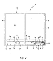
- FIGS. 1 to 9 show a first embodiment of the invention Eck Os 11 and the built-in inventive fitting 12.
- the corner cabinet 11 has a cabinet body 13, which is exemplified with a rectangular plan.
- the cabinet body 13 in turn consists of a rear wall 14, two side walls 15, 16 and a front side 17, which in turn is subdivided into a front wall 18 and a corner cabinet door 19 arranged adjacent thereto. Furthermore, a cabinet bottom 29 is provided. Front wall 18 and corner door 19 occupy the front 17 in approximately equal parts.
- the rectangular cabinet body 13 defines a correspondingly rectangular interior 20, which is accessible in about half the corner cabinet door 19.
- the interior 20 of the corner cupboard 11 is at least one tray 21, which is housed by means of the fitting 12 between an inner position in which the tray 21 is completely housed in the interior 20, and an external position in which Tray 21 at least partially beyond a plane 22 of a door opening of the corner cupboard 11 protrudes (see Figures 9A and 9E ) is controlled movably.
- a single tray 21 is housed in the corner cabinet 11.
- two or more superposed shelves could be arranged in the corner cabinet 11, which are preferably arranged one above the other in alignment in their respective inner or outer position.
- the tray 21 is exemplified in one-piece embodiment. However, it is also possible to use multi-part trays.
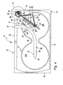
- the floor plan of the tray 21 is exemplified in the form of an eight.
- two substantially circular tray sections 23a, 23b are provided, which are connected to one another via a smaller diameter intermediate section 24.
- the tray 21 is fitted in the middle, so to speak.
- the sidecut is therefore provided so that the tray 21 in the tableau movement described in more detail below without hindrance by the cabinet periphery out of the door opening and can drive over the adjoining the door opening side wall 15 out into the outer position.
- the tray 21 is supported by two holding elements 25, 26 of the fitting 12 at two spaced bearing points 32, 33, wherein the holding elements 25, 26 each have a control device 27, 28 assigned to control the Tablarterrorism between the inner and outer position.
- the first control device 27 has a guide rail body 70 arranged on the cabinet bottom 29 with a guide track 30 and a guide member guided on the guide track 30 31, which in turn is connected to the holding element 25.
- a guide member 31 for example, a guide pin or - is suitable.
- the guide track is formed as a guide curve, with a first, substantially parallel to the plane 22 of the door opening extending straight guide portion 36 and an adjoining curved guide portion 37 which terminates at the level 22 of the door opening.
- the guideway body 70 is formed by a slotted guide, with a guide groove 38 which is flanked by two groove flanks 39, 40, in which case the guide track 30 is formed by one of the groove flanks 39, 40.
- This arrangement has the advantage that the guide member 31 is also fixed perpendicular to its current direction of movement.
- such a link guide also provides a pivot bearing for the guide member, which is rotated relative to the guideway body 70 during the tray movement.
- the second control device 28 has a lever arrangement 41, which is pivotally connected on the one hand to a stationary, located in the vicinity of the door opening pivot axis 42 and on the other hand at the associated second bearing 33 with the tray 21.
- the lever assembly 42 is formed such that the distance between the second bearing 33 and the pivot axis 42 in the Tablar Gay between the inner and outer position changes. That is, the lever length of the lever assembly shortens or lengthens during the tableau movement.
- the pivot axis 42 is located on a particular plate-like support unit 43, which in turn is fastened via a fastening element 44 on the bottom of the cabinet 29, on an upper cabinet cover or on the adjacent to the door opening side wall 15.
- a control cam 45 is formed, which controls the lever assembly 41 in the manner described in more detail below and is thus responsible for the shortening or lengthening of the lever length between the bearing 32 and the pivot axis 42.
- the lever assembly 41 has two levers 46, 47, of which a first lever 46 is pivotally mounted on the pivot axis 42 and serves as part of the sliding guide for a second lever 47.
- the second lever 47 is hinged to the second bearing point 33 on the tray 21 and at the same time displaceably guided on the first lever 46, wherein he on the other hand to a pivoting area at a constant distance to Swivel axis 42 located articulation point 48 is pivotally connected to the first lever 46 and at the same time guided controlled with its lever end 49 on the control cam 45.
- On the control cam 45 opposite the lever end 50 of the second lever is articulated as mentioned to the tray 21 and is there connected to the particular plate-like holding member 26, which in turn is connected to the tray 21.
- the first lever may be tubular and a kind of guide bushing 75 may be movably guided thereon, which in turn is connected to the second lever 47.
- the second lever 47 is designed as a toggle lever and has a second lever arm 53 which is articulated on the one hand to the guide bushing 75 and on the other hand connected via a hinge point 52 with the first lever arm 51, on the other hand in turn hingedly connected via the hinge point 48 to the first lever 46 is.
- FIG. 7 shown immersed at the lever end 49 of the second lever 47 downwardly projecting guide pin 54 in the control cam 45 and is guided at this during the Tablarterrorism.
- the curve of the control cam 45 controls the distance between the second bearing 33 and the pivot axis 42. This also changes the angle between the two lever arms 51, 53 of the toggle lever.
- the intake device 55 is according to the first embodiment also simultaneously the extension device.
- the entry or exit device 55 has at least one energy store in the form of a spring unit, which is arranged between two in the Tablarterrorism relative to each other movable points of the corner cabinet 11.
- a spring unit at least one helical spring is provided in a preferred manner, on the one hand fixed stationary on the first lever 46 and on the other hand is coupled in motion with the second bearing 33, for example, attached to the guide bushing 75.
- the cam also has a dead center 80, before the lever length or the distance to the pivot axis 42 is shortened and after the distance increases again. Characterized the coil spring is stretched or relaxed during shortening or lengthening of the lever length, resulting in that the spring force of the coil spring to support or autonomous execution of Tablarzi is provided in the inner position and support or independent execution of Tablarterrorism in the outer position.
- damping device 57 for damping the Tablarterrorism when entering the inner position and / or extending into the outer position.
- the damping device 57 can be arranged between two positions of the corner cupboard 11 which are movable relative to one another during the tableau movement, for example also fixedly connected on one side to the first lever 46 and on the other hand movably mounted in the region of the lever end of the second lever 47.
- the damping device 57 has a damping cylinder, which in turn has a cylinder housing 58 and a damping piston 58 displaceably mounted therein, which in turn is in turn connected to a piston rod 59 which is attached to the first lever 46 at the distal end of the piston.
- the damping piston 59 is either in the cylinder housing 58 retracted or extended while the extension of the damping piston 59, the air in the cylinder housing displaced and thereby the Tablarterrorism is damped.
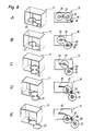
- FIGS. 8A to 8E the movement situation of the tray 21 is illustrated in the Tablarnism between the inner and the outer position.
- the tray 21 is initially housed in the inner position completely in the interior 20 of the corner cupboard 11.
- the corner cabinet door 19 is opened and the tray 21 is pulled out a little bit with its door opening next tray section 23 b from the door opening.
- FIG. 8B shows.
- the guide member 31 arranged on the underside of the first tray section 23a is guided on the guide curve, namely there on the first guide section 36.
- this movement is linear and directed parallel to the plane 22 of the door opening.
- the tray 21 pivots in total in the clockwise direction.
- the angle between the two lever arms 51, 53 of the toggle lever is reduced, that is, the distance between the second bearing 33 and the pivot axis 42 is reduced.
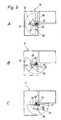
- FIG. 9 a second embodiment of the invention Eck Os 11 and fittings 12 is shown.
- the tray 21 has a semi-circular shape.
- the guide track body 70 is equipped with a linear guide track 30.
- a guide rail 65 is provided here, which is fastened to the bottom of the cabinet 29 and extends from the door opening, directed perpendicular to the plane 22 of the door opening into the interior 20.
- guide rail 65 located on the tray 21 guide member 31 is guided linearly movable.
- the second controller 28 also has a lever assembly 41 in which the distance between the second location 33 and the pivot axis 42 changes during the tray movement.
- FIG. 9A shows the tray 21 in the inner position.
- the guide member 31 fastened to the tray 21 is moved linearly in the guide rail 65 towards the door opening.
- the tray is pivoted about the pivot axis 42, wherein the lever length, that is, the distance between the second bearing 33 and the pivot axis 42nd changes.
- FIG. 9B shows the tray reaches its in FIG. 9C illustrated external position, wherein the half of the semicircular shelf 21 is located outside the door opening.
- the guide member 31 is also located in front of the plane of the door opening and is for example via a telescopic member 90 in contact with the guide rail 65.
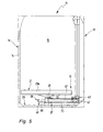
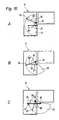
- FIG. 10 shows a third embodiment of the invention Eck Os 11 or fitting 12.
- This embodiment is substantially consistent with the second embodiment described above.
- the essential difference is that the lever arrangement 41 of the second control device 28 is designed such that the distance between the second bearing 33 and the pivot axis 42 in the Tablarterrorism between the inner and outer position is constant. It is here a single one-piece lever 67 which is hinged to the tray 21.
- the second bearing 33 describes a circular arc about the pivot axis 42.
- the tray movement is otherwise similar to that described in the second embodiment, whereby the tray 21 protrudes a bit out of the door opening until it has reached its outer position which protrudes beyond the half of the tray surface beyond the plane 22 of the door opening.
- a guide rail 65 provided on which the mounted on the underside of the tray guide member 31 is guided linearly displaceable. In the outer position, the guide member 31 is in turn connected via a telescopic member 90 with the guide rail 65.
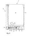
- FIG. 11 shows a fourth embodiment of the invention Eck Os 11 and fittings 12.
- This embodiment is substantially consistent with the third embodiment described above. It is therefore also provided here a one-piece lever, which is hinged to the tray.
- the tray now has a different shape, which is rather elongated here.
- a guide rail 65 is provided, which, however, is arranged at a greater distance from the pivot axis 42 in comparison to the second or third embodiment.
- the guide rail 65 terminates approximately in the middle of the plane 22 of the door opening.
- the guide member 31 is in turn connected via a telescopic member 90 with the guide rail 65.
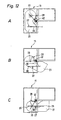
- FIG. 12 a fifth embodiment of the invention Eck Os 11 and fittings 12 shown.
- the tray shape of the tray 21 substantially corresponds to that of the fourth embodiment.
- a lever arrangement 41 is arranged, in which the distance between the second bearing 33 and the pivot axis 42 changes during the tableau movement.
- a guide rail 65 is provided which terminates substantially in the middle of the door opening.
- FIG. 12C shown outside position at least half of the tray surface outside the corner cabinet 11 is arranged and the Guide member 31 is connected via a telescopic member 90 with the guide rail 65.
Landscapes
- Combinations Of Kitchen Furniture (AREA)
Applications Claiming Priority (1)
| Application Number | Priority Date | Filing Date | Title |
|---|---|---|---|
| DE200610055807 DE102006055807A1 (de) | 2006-11-27 | 2006-11-27 | Beschlag für einen Eckschrank und Eckschrank |
Publications (2)
| Publication Number | Publication Date |
|---|---|
| EP1925237A2 true EP1925237A2 (fr) | 2008-05-28 |
| EP1925237A3 EP1925237A3 (fr) | 2010-12-29 |
Family
ID=39259510
Family Applications (1)
| Application Number | Title | Priority Date | Filing Date |
|---|---|---|---|
| EP07018572A Withdrawn EP1925237A3 (fr) | 2006-11-27 | 2007-09-21 | Armature pour une armoire angulaire et armoire angulaire |
Country Status (2)
| Country | Link |
|---|---|
| EP (1) | EP1925237A3 (fr) |
| DE (1) | DE102006055807A1 (fr) |
Cited By (11)
| Publication number | Priority date | Publication date | Assignee | Title |
|---|---|---|---|---|
| WO2008135270A1 (fr) * | 2007-05-08 | 2008-11-13 | Vauth-Sagel Holding Gmbh & Co. Kg | Ferrure pour armoire d'angle comprenant un plateau monobloc extractible |
| EP2253244A1 (fr) * | 2009-05-22 | 2010-11-24 | Ninkaplast GmbH | Armature rotative et extensible pour armoire d'angle |
| WO2011042213A1 (fr) * | 2009-10-05 | 2011-04-14 | Compagnucci Holding S.P.A. | Armoire comportant une ou plusieurs étagères extractibles |
| EP2353436A1 (fr) * | 2010-02-05 | 2011-08-10 | Hetal-Werke Franz Hettich GmbH & Co. | Ferrure pour une armoire d'angle et armoire d'angle |
| EP2353441A1 (fr) * | 2010-02-05 | 2011-08-10 | Hetal-Werke Franz Hettich GmbH & Co. KG | Armature pour une armoire de coin |
| US20110193455A1 (en) * | 2010-02-05 | 2011-08-11 | Heinrich J. Kesseböhmer KG | Fitting for a Corner Cabinet |
| DE202012100376U1 (de) * | 2012-02-03 | 2013-05-06 | Ninkaplast Gmbh | Abfallsammelsystem |
| US20140225492A1 (en) * | 2011-05-23 | 2014-08-14 | Kesseböhmer Holding e.K. | Fitting for corner cabinets and pull-in device for said type of fitting |
| DE202015102233U1 (de) * | 2015-05-04 | 2016-08-05 | Hetal-Werke Franz Hettich Gmbh & Co. Kg | Schwenkeinrichtung für einen Tablarhalter eines Eckschrank-Möbels |
| EP3804564A1 (fr) | 2019-10-10 | 2021-04-14 | Peka-Metall AG | Dispositif d'extraction pour armoire de coin |
| US20240115040A1 (en) * | 2021-01-25 | 2024-04-11 | Paul Hettich Gmbh & Co. Kg | Furniture element and piece of furniture |
Families Citing this family (3)
| Publication number | Priority date | Publication date | Assignee | Title |
|---|---|---|---|---|
| IT201700069780A1 (it) * | 2017-06-22 | 2018-12-22 | Inoxa Srl | Armadio con ripiani estraibili e relativo meccanismo estrattore perfezionato |
| DE202019100837U1 (de) * | 2019-02-14 | 2020-05-18 | Ninkaplast Gmbh | Schrank mit ausziehbarem Tablar |
| DE202022103839U1 (de) | 2022-07-08 | 2023-10-17 | Ninkaplast Gmbh | Dreh- und Ausziehbeschlag für einen Eckschrank |
Citations (2)
| Publication number | Priority date | Publication date | Assignee | Title |
|---|---|---|---|---|
| DE202004011200U1 (de) | 2004-07-16 | 2005-12-01 | Heinrich J. Kesseböhmer KG | Eckschrank, insbesondere Kücheneckschrank |
| EP1723875A1 (fr) | 2005-04-29 | 2006-11-22 | Formenti & Giovenzana S.p.A. | Accessoire d'ameublement |
Family Cites Families (4)
| Publication number | Priority date | Publication date | Assignee | Title |
|---|---|---|---|---|
| DE19514009A1 (de) * | 1995-04-13 | 1996-10-17 | Vauth Sagel Gmbh & Co | Eckschrank zum Aufstellen in einer Raumecke |
| IT242483Y1 (it) * | 1996-03-29 | 2001-06-14 | Compagnucci Spa | Intelaiatura componibile porta-cestelli per mobili d'angolo destri osinistri |
| ATE265166T1 (de) * | 1999-01-20 | 2004-05-15 | Westermann Kg | Schrankmöbel |
| DE502004011233D1 (de) * | 2004-04-26 | 2010-07-15 | Peka Metall Ag | Eckschrankauszugvorrichtung |
-
2006
- 2006-11-27 DE DE200610055807 patent/DE102006055807A1/de not_active Ceased
-
2007
- 2007-09-21 EP EP07018572A patent/EP1925237A3/fr not_active Withdrawn
Patent Citations (2)
| Publication number | Priority date | Publication date | Assignee | Title |
|---|---|---|---|---|
| DE202004011200U1 (de) | 2004-07-16 | 2005-12-01 | Heinrich J. Kesseböhmer KG | Eckschrank, insbesondere Kücheneckschrank |
| EP1723875A1 (fr) | 2005-04-29 | 2006-11-22 | Formenti & Giovenzana S.p.A. | Accessoire d'ameublement |
Cited By (15)
| Publication number | Priority date | Publication date | Assignee | Title |
|---|---|---|---|---|
| WO2008135270A1 (fr) * | 2007-05-08 | 2008-11-13 | Vauth-Sagel Holding Gmbh & Co. Kg | Ferrure pour armoire d'angle comprenant un plateau monobloc extractible |
| CN101889770B (zh) * | 2009-05-22 | 2014-05-14 | 宁卡塑料有限公司 | 用于角柜的旋转拉出式配件 |
| EP2253244A1 (fr) * | 2009-05-22 | 2010-11-24 | Ninkaplast GmbH | Armature rotative et extensible pour armoire d'angle |
| WO2011042213A1 (fr) * | 2009-10-05 | 2011-04-14 | Compagnucci Holding S.P.A. | Armoire comportant une ou plusieurs étagères extractibles |
| US8911035B2 (en) | 2010-02-05 | 2014-12-16 | Hetal-Werke Franz Hettich Gmbh & Co. Kg | Fitting for a corner cupboard and a corner cupboard |
| US20110193455A1 (en) * | 2010-02-05 | 2011-08-11 | Heinrich J. Kesseböhmer KG | Fitting for a Corner Cabinet |
| EP2353441A1 (fr) * | 2010-02-05 | 2011-08-10 | Hetal-Werke Franz Hettich GmbH & Co. KG | Armature pour une armoire de coin |
| EP2353436A1 (fr) * | 2010-02-05 | 2011-08-10 | Hetal-Werke Franz Hettich GmbH & Co. | Ferrure pour une armoire d'angle et armoire d'angle |
| US20140225492A1 (en) * | 2011-05-23 | 2014-08-14 | Kesseböhmer Holding e.K. | Fitting for corner cabinets and pull-in device for said type of fitting |
| US9119470B2 (en) * | 2011-05-23 | 2015-09-01 | Kesseböhmer Holding e.K. | Fitting for corner cabinets and pull-in device for said type of fitting |
| DE202012100376U1 (de) * | 2012-02-03 | 2013-05-06 | Ninkaplast Gmbh | Abfallsammelsystem |
| DE202015102233U1 (de) * | 2015-05-04 | 2016-08-05 | Hetal-Werke Franz Hettich Gmbh & Co. Kg | Schwenkeinrichtung für einen Tablarhalter eines Eckschrank-Möbels |
| EP3804564A1 (fr) | 2019-10-10 | 2021-04-14 | Peka-Metall AG | Dispositif d'extraction pour armoire de coin |
| US20240115040A1 (en) * | 2021-01-25 | 2024-04-11 | Paul Hettich Gmbh & Co. Kg | Furniture element and piece of furniture |
| US12357088B2 (en) * | 2021-01-25 | 2025-07-15 | Paul Hettich Gmbh & Co. Kg | Furniture element and piece of furniture |
Also Published As
| Publication number | Publication date |
|---|---|
| DE102006055807A1 (de) | 2008-05-29 |
| EP1925237A3 (fr) | 2010-12-29 |
Similar Documents
| Publication | Publication Date | Title |
|---|---|---|
| EP1925237A2 (fr) | Armature pour une armoire angulaire et armoire angulaire | |
| EP1925238B1 (fr) | Armature pour une armoire angulaire et armoire angulaire | |
| EP2841668B1 (fr) | Ferrure de porte | |
| EP3087866B1 (fr) | Armature pour une armoire angulaire et armoire angulaire dotée d'une armature | |
| AT502937B1 (de) | Schrankförmiges möbel | |
| EP1925239B1 (fr) | Armoire de coin | |
| DE102015106917B4 (de) | Möbelscharnier mit einem Dämpfer und einer Feder | |
| EP1949817A2 (fr) | Armature pour une armoire de coin | |
| EP2092850B1 (fr) | Armature pour une armoire de coin | |
| EP2268882A1 (fr) | Charnière de meuble | |
| WO2012145769A1 (fr) | Meuble doté d'un corps et un clapet pliant | |
| EP1964490B1 (fr) | Armoire d'angle, en particulier armoire d'angle de cuisine | |
| DE102005018552A1 (de) | Halteelement | |
| EP2353438A2 (fr) | Armature pour une armoire angulaire | |
| DE202015104436U1 (de) | Vorrichtung zum Bewegen eines bewegbaren Möbelteils in eine Öffnungsrichtung in Bezug zu einem Möbelkorpus eines Möbels | |
| EP2064971A1 (fr) | Armature pour armoire angulaire | |
| AT508351B1 (de) | Dämpfungseinheit sowie faltbare zusatzplatte und tisch | |
| WO2019014693A1 (fr) | Ensemble servant à déplacer une partie de meuble mobile | |
| EP2353441B1 (fr) | Armature pour une armoire de coin | |
| DE202010002230U1 (de) | Beschlag für einen Eckschrank und Eckschrank | |
| EP2191745B1 (fr) | Armature pour une armoire angulaire | |
| EP3326491A1 (fr) | Ferrure destinée au logement mobile commandé par engrenage d'une étagère dans un élément d'angle | |
| DE202005020863U1 (de) | Dämpfeinrichtung für schwenkbare Möbelteile | |
| DE10234797B4 (de) | Beschlag für einen Eckschrank | |
| EP3278689A1 (fr) | Armature pour une armoire angulaire |
Legal Events
| Date | Code | Title | Description |
|---|---|---|---|
| PUAI | Public reference made under article 153(3) epc to a published international application that has entered the european phase |
Free format text: ORIGINAL CODE: 0009012 |
|
| AK | Designated contracting states |
Kind code of ref document: A2 Designated state(s): AT BE BG CH CY CZ DE DK EE ES FI FR GB GR HU IE IS IT LI LT LU LV MC MT NL PL PT RO SE SI SK TR |
|
| AX | Request for extension of the european patent |
Extension state: AL BA HR MK RS |
|
| PUAL | Search report despatched |
Free format text: ORIGINAL CODE: 0009013 |
|
| AK | Designated contracting states |
Kind code of ref document: A3 Designated state(s): AT BE BG CH CY CZ DE DK EE ES FI FR GB GR HU IE IS IT LI LT LU LV MC MT NL PL PT RO SE SI SK TR |
|
| AX | Request for extension of the european patent |
Extension state: AL BA HR MK RS |
|
| AKY | No designation fees paid | ||
| REG | Reference to a national code |
Ref country code: DE Ref legal event code: R108 |
|
| 17P | Request for examination filed |
Effective date: 20110629 |
|
| RBV | Designated contracting states (corrected) |
Designated state(s): AT BE BG CH CY CZ DE DK EE ES FI FR GB GR HU IE IS IT LI LT LU LV MC MT NL PL PT RO SE SI SK TR |
|
| REG | Reference to a national code |
Ref country code: DE Ref legal event code: R108 Effective date: 20110907 |
|
| STAA | Information on the status of an ep patent application or granted ep patent |
Free format text: STATUS: THE APPLICATION IS DEEMED TO BE WITHDRAWN |
|
| 18D | Application deemed to be withdrawn |
Effective date: 20160401 |