EP1923915A2 - Wärmeableitungssystem mit Hohlkörper zur Wärmeableitung - Google Patents
Wärmeableitungssystem mit Hohlkörper zur Wärmeableitung Download PDFInfo
- Publication number
- EP1923915A2 EP1923915A2 EP07253040A EP07253040A EP1923915A2 EP 1923915 A2 EP1923915 A2 EP 1923915A2 EP 07253040 A EP07253040 A EP 07253040A EP 07253040 A EP07253040 A EP 07253040A EP 1923915 A2 EP1923915 A2 EP 1923915A2
- Authority
- EP
- European Patent Office
- Prior art keywords
- heat dissipating
- heat
- bottom wall
- cavity body
- working fluid
- Prior art date
- Legal status (The legal status is an assumption and is not a legal conclusion. Google has not performed a legal analysis and makes no representation as to the accuracy of the status listed.)
- Withdrawn
Links
Images



Classifications
-
- H—ELECTRICITY
- H10—SEMICONDUCTOR DEVICES; ELECTRIC SOLID-STATE DEVICES NOT OTHERWISE PROVIDED FOR
- H10W—GENERIC PACKAGES, INTERCONNECTIONS, CONNECTORS OR OTHER CONSTRUCTIONAL DETAILS OF DEVICES COVERED BY CLASS H10
- H10W40/00—Arrangements for thermal protection or thermal control
- H10W40/70—Fillings or auxiliary members in containers or in encapsulations for thermal protection or control
- H10W40/73—Fillings or auxiliary members in containers or in encapsulations for thermal protection or control for cooling by change of state
-
- G—PHYSICS
- G06—COMPUTING OR CALCULATING; COUNTING
- G06F—ELECTRIC DIGITAL DATA PROCESSING
- G06F1/00—Details not covered by groups G06F3/00 - G06F13/00 and G06F21/00
- G06F1/16—Constructional details or arrangements
- G06F1/18—Packaging or power distribution
- G06F1/181—Enclosures
-
- G—PHYSICS
- G06—COMPUTING OR CALCULATING; COUNTING
- G06F—ELECTRIC DIGITAL DATA PROCESSING
- G06F1/00—Details not covered by groups G06F3/00 - G06F13/00 and G06F21/00
- G06F1/16—Constructional details or arrangements
- G06F1/20—Cooling means
Definitions
- the invention relates to heat dissipation, more particularly to a heat dissipating system having a heat dissipating cavity body.
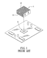
- a conventional heat sink 1 includes a substantially large contact surface 11 in contact with a heat source 2, and a plurality of heat dissipating fins 12.
- the contact surface 11 absorbs heat generated by the heat source 2, and the heat is dissipated through the heat dissipating fins 12 which exchange heat with external cold air by natural convection.
- the contact parts of the heat sink 1 and the heat source 2 are rigid, and since errors in surface flatness of the contact surfaces inevitably occur, a small gap is typically formed between the contact surface 11 of the heat sink 1 and the heat source 2. As such, the contact surface 11 of the heat sink 1 cannot contact tightly the heat source 2, thereby affecting the heat dissipating efficiencyof the heat sink 1 . Further, since the heat dissipating purpose of the heat sink 1 is achieved by increasing the heat dissipating area thereof, the volume of the conventional heat sink 1 is thus very large. Moreover, because the area of heat conduction is limited, the temperature of the conventional heat sink 1 increases after a long period of use, thereby adversely affecting the heat dissipating effect.
- the object of the present invention is to provide a heat dissipating system having a heat dissipating cavity body so as to enhance the heat dissipating effect and efficiency of the heat dissipating system.
- a heat dissipating system comprises a heat dissipating cavity body defining a receiving space and having a bottom wall adapted to contact a heat source, a working fluid disposed in the receiving space and adapted to absorb heat generated by the heat source, and a heat exchange unit for exchanging heat with the working fluid.
- the bottom wall is made of a thin metal plate, and is flexible to deform so that when the bottom wall is pressed against the heat source, the bottom wall conforms to and contacts tightly a contact surface of the heat source.
- a heat dissipating cavity body is adapted to contact a heat source, and comprises top and bottom walls, and a surrounding wall connected between the top and bottom walls to define a receiving space which is adapted to contain a working fluid.
- the bottom wall is made of a thin metal plate, and is flexible to deform so that when the bottom wall is pressed against the heat source, the bottom wall conforms to and contacts tightly a contact surface of the heat source.
- the first preferred embodiment of a heat dissipating system is adapted to be installed in a computer module 6, and is shown to comprise a heat dissipating cavity body 3 and a heat exchange unit 4.
- the heat dissipating cavity body 3 in this embodiment, is adapted to be disposed in a lower chamber of the computer module 6, and is made of a thin metal plate having a thickness of below 0.5mm.
- the heat dissipating cavity body 3 has top and bottom walls 33, 34, and a surrounding wall 32 connected between the top and bottom walls 33, 34 to define a receiving space 31.
- the bottom wall 34 is convexed downwardly in a normal state, and is adapted to contact a heat source 61 of the computer module 6.
- the surrounding wall 32 is pleated.
- the top and bottom walls 33, 34 (only the top wall 33 is visible) are placed vertically.
- the heat exchange unit 4 includes a condenser 41, a thermoelectric cooler 42, a heat sink 43, and a fan 44.
- the condenser 41 has a vapor-receiving section 411 formed on a top end thereof, a liquid-receiving section 412 formed on a bottom end thereof, and a plurality of channels 413 connected between the vapor-receiving and liquid-receiving sections 411, 412.
- the thermoelectric cooler 42 is controlled through a circuit, and has a cold side 421 in contact with the liquid-receiving section 412, and a hot side 422 opposite to the cold side 421.
- the cold side 421 has a cooling function so as to keep the liquid-receiving section 412 at a constant temperature.
- the heat sink 43 is disposed proximate to the condenser 41, and has an L-shaped configuration.
- the heat sink 43 has a horizontal plate 431 in contact with the hot side 422 of the thermoelectric cooler 42, a vertical plate 432 connected to an end periphery of the horizontal plate 431 and parallel to the condenser 41, and a plurality of fins 433 provided on the vertical plate 432.
- the fan 44 is disposed proximate to the condenser 41 and the heat sink 43, and directs a current of cold air toward the condenser 41 and the heat sink 43, as best shown in Figure 3.
- a tubing unit 5 interconnects the heat dissipating cavity body 3 and the condenser 41, and includes a vapor-flowing tube 51 connected fluidly to the cavity body 3 and the vapor-receiving section 411 of the condenser 41, and a liquid-flowing tube 52 connected fluidly to the cavity body 3 and the liquid-receiving section 412 of the condenser 41.
- the vapor-flowing and liquid-flowing tubes 51, 52, the condenser 41, and the cavity body 3 form a closed circulating loop.
- a working fluid 30 is condensable and is injected into the heat dissipating system of the present invention after the vapor-flowing and liquid-flowing tubes 51, 52, the cavity body 3, and the condenser 41 are evacuated, so that the working fluid 30 circulates in a vacuum environment.
- the working fluid 30 is a coolant that is in a liquid state at room temperature.
- the working fluid 30 may be a super-thermal-conductive liquid.
- the bottom wall 34 of the heat dissipating cavity body 3 is placed in contact with the heat source 61 of the computer module 6. Because the cavity body 3 is made of a thin metal plate, the bottom wall 34 and the pleated surrounding wall 32 are flexible to deform easily when acted upon by an external force. As such, when the bottom wall 34 is pressed against the heat source 61, the bottom wall 34 conforms to and contacts tightly a contact surface of the heat source 61, thereby enhancing tight contact between the cavity body 3 and the heat source 61.
- the working fluid 30 is in a liquid state and is contained in the receiving space 31 of the cavity body 3.
- the liquid-state working fluid 30 in the cavity body 3 absorbs heat generated by the heat source 61 through heat conduction, and is vaporized.
- the pressure inside the cavity body 3 increases as the working fluid 30 is vaporized, and the vaporized working fluid 30 is pressurized to flow upward by natural convection through the vapor-flowing tube 51 from a high-density region, which is the cavity body 3, into a low-density region, which is the vapor-receiving section 411 of the condenser 41.
- the fan 44 blows cold air toward the condenser 41 and the heat sink 43 so that the condenser 41 and the heat sink 43 exchange heat with the cold air.
- the vaporized working fluid 30 from the vapor-flowing tube 51 is condensed in the condenser 41, and flows downward through the channels 413 by gravity into the liquid-receiving section 412 of the condenser 4.
- thermoelectric cooler 42 Through the cooling function of the cold side 421 of the thermoelectric cooler 42, the temperature of the working fluid 30 in a condensed state and in the liquid-receiving section 412 of the condenser 41 continues to drop to a preset value, and the hot side 422 of the thermoelectric cooler 42 transfers the heat from the condensed working fluid 30 to the heat sink 43, which dissipates the heat.
- the cooled condensed working fluid 30 in the liquid-receiving section 412 then flows back into the receiving space 31 of the cavity body 3 through the liquid-flowing tube 52 by gravity so as to repeat the aforementioned steps.
- heat is effectively dissipated.
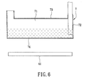
- a heat dissipating system according to the second preferred embodiment of the present invention is shown to be similar to the first preferred embodiment.
- the heat dissipating cavity body 7 is made of a thin metal plate.
- the bottom wall 74 of the heat dissipating cavity body 7 is flat. When the bottom wall 74 is pressed against the contact surface of the heat source 61, the bottom wall 74 similarly conforms to and contacts tightly the contact surface of the heat source 61.
- a heat dissipating system according to the third preferred embodiment of the present invention is shown to be similar to the first preferred embodiment.
- the receiving space 31' of the heat dissipating cavity body 3' is tightly closed, and is non-communicated with the condenser 41 and the tubing unit 5' .
- the top wall 33' has an inner surface formed with a plurality of protrusions 331 and depressions 332 so as to increase a surface area of the inner surface of the top wall 33'.
- the cold side 421 of the thermoelectric cooler 42 is directly in contact with the top wall 33' of the cavity body 3'.
- the tubing unit 5' further includes an intermediate tube 53 connected fluidly between the vapor-flowing and liquid-flowing tubes 51, 52 and in contact with the hot side 422 of the thermoelectric cooler 42.
- the working fluid 30 is further disposed in the condenser 41 and the tubing unit 5'.
- the liquid-state working fluid 30 in the receiving space 31' absorbs heat generated by the heat source 61, it will vaporize upwardly toward the top wall 33' .
- the vaporized working fluid 30 then exchanges heat with the cavity body 3'.
- the vaporized working fluid 30 condenses, and flows downwardly to the bottom wall 34' so as to repeat the aforementioned vaporization and condensation processes.
- the hot side 422 of the thermoelectric cooler 42 transfers heat resulting from condensation of the vaporized working fluid 30 in the cavity body 3' to the intermediate tube 53 so as to vaporize the liquid-state working fluid 30 in the intermediate tube 53.
- the vaporized working fluid 30 in the intermediate tube 53 then flows upward by natural convection to the vapor-receiving section 411 of the condenser 41 through the vapor-flowing tube 51, exchanges heat with the condenser 41, condenses, flows downward through the channels 413 by gravity into the liquid-receiving section 412 of the condenser 41, and back into the intermediate tube 53 through the liquid-flowing tube 52 so as to repeat the aforementioned steps.
- heat dissipation is similarly and efficiently achieved using the third preferred embodiment.
- the fan 44 may be attached to one side of the condenser 41 depending on the size of the condenser 41. As such, the heat dissipating effect and efficiency of the condenser 41 may be enhanced.
- the tubing unit 5 may interconnect in series or in parallel a plurality of the heat dissipating cavity bodies 3, which in turn, are adapted to contact respectively heat sources of the computer module 6.
- the heat dissipating system of the present invention may also be applicable to an engine or a machine of a car, or any other article that needs heat dissipation.
Landscapes
- Engineering & Computer Science (AREA)
- Theoretical Computer Science (AREA)
- Human Computer Interaction (AREA)
- Physics & Mathematics (AREA)
- General Engineering & Computer Science (AREA)
- General Physics & Mathematics (AREA)
- Computer Hardware Design (AREA)
- Power Engineering (AREA)
- Cooling Or The Like Of Semiconductors Or Solid State Devices (AREA)
- Cooling Or The Like Of Electrical Apparatus (AREA)
Applications Claiming Priority (1)
| Application Number | Priority Date | Filing Date | Title |
|---|---|---|---|
| CN200610145734.4A CN101182976A (zh) | 2006-11-14 | 2006-11-14 | 散热腔体及具有散热腔体的相变散热装置 |
Publications (2)
| Publication Number | Publication Date |
|---|---|
| EP1923915A2 true EP1923915A2 (de) | 2008-05-21 |
| EP1923915A3 EP1923915A3 (de) | 2008-07-02 |
Family
ID=39086077
Family Applications (1)
| Application Number | Title | Priority Date | Filing Date |
|---|---|---|---|
| EP07253040A Withdrawn EP1923915A3 (de) | 2006-11-14 | 2007-08-02 | Wärmeableitungssystem mit Hohlkörper zur Wärmeableitung |
Country Status (2)
| Country | Link |
|---|---|
| EP (1) | EP1923915A3 (de) |
| CN (1) | CN101182976A (de) |
Cited By (1)
| Publication number | Priority date | Publication date | Assignee | Title |
|---|---|---|---|---|
| WO2016095507A1 (zh) * | 2014-12-16 | 2016-06-23 | 中兴通讯股份有限公司 | 一种散热装置、电路板及终端 |
Families Citing this family (7)
| Publication number | Priority date | Publication date | Assignee | Title |
|---|---|---|---|---|
| JP6134384B2 (ja) | 2012-06-12 | 2017-05-24 | シエル・インターナシヨネイル・リサーチ・マーチヤツピイ・ベー・ウイShell Internationale Research Maatschappij Besloten Vennootshap | 液化ストリームを加熱するための装置および方法 |
| KR102060846B1 (ko) * | 2012-06-12 | 2019-12-30 | 쉘 인터내셔날 리써취 마트샤피지 비.브이. | 액화 스트림을 가열하기 위한 장치 및 방법 |
| CN104410370A (zh) * | 2014-12-10 | 2015-03-11 | 成都锐思灵科技有限公司 | 一种微波功率放大器特殊相变散热器 |
| CN104410369A (zh) * | 2014-12-10 | 2015-03-11 | 成都锐思灵科技有限公司 | 相变散热式微波功率放大器 |
| CN107771011A (zh) * | 2017-09-28 | 2018-03-06 | 深圳市英威腾电气股份有限公司 | 一种柔性相变散热装置 |
| CN110021570B (zh) * | 2019-04-10 | 2022-06-14 | 嘉龙(平潭)科技有限公司 | 三维相变化远程散热模块 |
| CN113382611B (zh) * | 2021-06-21 | 2022-12-13 | 上海电力大学 | 一种相态变化的散热贴 |
Family Cites Families (5)
| Publication number | Priority date | Publication date | Assignee | Title |
|---|---|---|---|---|
| US4997032A (en) * | 1987-09-25 | 1991-03-05 | Minnesota Mining And Manufacturing Company | Thermal transfer bag |
| WO1996023398A1 (en) * | 1995-01-25 | 1996-08-01 | Aavid Engineering, Inc. | Thermal management system |
| SG64996A1 (en) * | 1997-07-08 | 1999-05-25 | Dso National Laborataries | A heat sink |
| JP2000353774A (ja) * | 1999-06-11 | 2000-12-19 | Mitsubishi Electric Corp | 水蒸発式発熱体冷却装置 |
| GB2388473B (en) * | 2002-05-08 | 2005-09-21 | Sun Microsystems Inc | Compliant heat sink interface |
-
2006
- 2006-11-14 CN CN200610145734.4A patent/CN101182976A/zh active Pending
-
2007
- 2007-08-02 EP EP07253040A patent/EP1923915A3/de not_active Withdrawn
Cited By (1)
| Publication number | Priority date | Publication date | Assignee | Title |
|---|---|---|---|---|
| WO2016095507A1 (zh) * | 2014-12-16 | 2016-06-23 | 中兴通讯股份有限公司 | 一种散热装置、电路板及终端 |
Also Published As
| Publication number | Publication date |
|---|---|
| CN101182976A (zh) | 2008-05-21 |
| EP1923915A3 (de) | 2008-07-02 |
Similar Documents
| Publication | Publication Date | Title |
|---|---|---|
| US20080078202A1 (en) | Heat dissipating system and method | |
| EP1909053A2 (de) | Wärmeableitsystem und -verfahren | |
| US20080105404A1 (en) | Heat dissipating system having a heat dissipating cavity body | |
| EP1923915A2 (de) | Wärmeableitungssystem mit Hohlkörper zur Wärmeableitung | |
| US6394175B1 (en) | Top mounted cooling device using heat pipes | |
| US6967841B1 (en) | Cooling assembly for electronics drawer using passive fluid loop and air-cooled cover | |
| CN102458088B (zh) | 电子装置的散热结构 | |
| US7525801B2 (en) | Computer module | |
| US9261309B2 (en) | Loop heat pipe and manufacturing method thereof | |
| JP6015675B2 (ja) | 冷却装置及びそれを用いた電子機器 | |
| CN103081581B (zh) | 用于冷却电子装置的系统 | |
| US8813834B2 (en) | Quick temperature-equlizing heat-dissipating device | |
| US5458189A (en) | Two-phase component cooler | |
| US20060162903A1 (en) | Liquid cooled thermosiphon with flexible partition | |
| US20090151906A1 (en) | Heat sink with vapor chamber | |
| WO2010084717A1 (ja) | 冷却装置 | |
| US20090151905A1 (en) | Heat sink with vapor chamber | |
| EP3006885B1 (de) | Hybrid-wärmerohreinheit mit verbundenen rippen auf der grundplatte | |
| WO2015146110A1 (ja) | 相変化冷却器および相変化冷却方法 | |
| US20140054009A1 (en) | Cooling plate and water cooling device having the same | |
| US20200064074A1 (en) | Condenser and heat dissipation apparatus | |
| EP1923770A1 (de) | Computermodul | |
| JP2013007501A (ja) | 冷却装置 | |
| CN104303293B (zh) | 冷却装置的连接结构、冷却装置和连接冷却装置的方法 | |
| CN101726136B (zh) | 两段式膨胀冷却系统及其蒸发器 |
Legal Events
| Date | Code | Title | Description |
|---|---|---|---|
| PUAI | Public reference made under article 153(3) epc to a published international application that has entered the european phase |
Free format text: ORIGINAL CODE: 0009012 |
|
| AK | Designated contracting states |
Kind code of ref document: A2 Designated state(s): AT BE BG CH CY CZ DE DK EE ES FI FR GB GR HU IE IS IT LI LT LU LV MC MT NL PL PT RO SE SI SK TR |
|
| AX | Request for extension of the european patent |
Extension state: AL BA HR MK RS |
|
| PUAL | Search report despatched |
Free format text: ORIGINAL CODE: 0009013 |
|
| AK | Designated contracting states |
Kind code of ref document: A3 Designated state(s): AT BE BG CH CY CZ DE DK EE ES FI FR GB GR HU IE IS IT LI LT LU LV MC MT NL PL PT RO SE SI SK TR |
|
| AX | Request for extension of the european patent |
Extension state: AL BA HR MK RS |
|
| 17P | Request for examination filed |
Effective date: 20080528 |
|
| 17Q | First examination report despatched |
Effective date: 20080818 |
|
| AKX | Designation fees paid |
Designated state(s): DE FR GB |
|
| STAA | Information on the status of an ep patent application or granted ep patent |
Free format text: STATUS: THE APPLICATION IS DEEMED TO BE WITHDRAWN |
|
| 18D | Application deemed to be withdrawn |
Effective date: 20081230 |