EP1923550A2 - Ensemble de dérivation pour un refroidisseur d'air de charge - Google Patents
Ensemble de dérivation pour un refroidisseur d'air de charge Download PDFInfo
- Publication number
- EP1923550A2 EP1923550A2 EP07120237A EP07120237A EP1923550A2 EP 1923550 A2 EP1923550 A2 EP 1923550A2 EP 07120237 A EP07120237 A EP 07120237A EP 07120237 A EP07120237 A EP 07120237A EP 1923550 A2 EP1923550 A2 EP 1923550A2
- Authority
- EP
- European Patent Office
- Prior art keywords
- passageway
- gas
- inlet
- gas outlet
- outlet
- Prior art date
- Legal status (The legal status is an assumption and is not a legal conclusion. Google has not performed a legal analysis and makes no representation as to the accuracy of the status listed.)
- Withdrawn
Links
Images

Classifications
-
- F—MECHANICAL ENGINEERING; LIGHTING; HEATING; WEAPONS; BLASTING
- F02—COMBUSTION ENGINES; HOT-GAS OR COMBUSTION-PRODUCT ENGINE PLANTS
- F02B—INTERNAL-COMBUSTION PISTON ENGINES; COMBUSTION ENGINES IN GENERAL
- F02B29/00—Engines characterised by provision for charging or scavenging not provided for in groups F02B25/00, F02B27/00 or F02B33/00 - F02B39/00; Details thereof
- F02B29/04—Cooling of air intake supply
- F02B29/0406—Layout of the intake air cooling or coolant circuit
- F02B29/0418—Layout of the intake air cooling or coolant circuit the intake air cooler having a bypass or multiple flow paths within the heat exchanger to vary the effective heat transfer surface
-
- F—MECHANICAL ENGINEERING; LIGHTING; HEATING; WEAPONS; BLASTING
- F02—COMBUSTION ENGINES; HOT-GAS OR COMBUSTION-PRODUCT ENGINE PLANTS
- F02B—INTERNAL-COMBUSTION PISTON ENGINES; COMBUSTION ENGINES IN GENERAL
- F02B33/00—Engines characterised by provision of pumps for charging or scavenging
- F02B33/44—Passages conducting the charge from the pump to the engine inlet, e.g. reservoirs
-
- F—MECHANICAL ENGINEERING; LIGHTING; HEATING; WEAPONS; BLASTING
- F02—COMBUSTION ENGINES; HOT-GAS OR COMBUSTION-PRODUCT ENGINE PLANTS
- F02B—INTERNAL-COMBUSTION PISTON ENGINES; COMBUSTION ENGINES IN GENERAL
- F02B37/00—Engines characterised by provision of pumps driven at least for part of the time by exhaust
-
- Y—GENERAL TAGGING OF NEW TECHNOLOGICAL DEVELOPMENTS; GENERAL TAGGING OF CROSS-SECTIONAL TECHNOLOGIES SPANNING OVER SEVERAL SECTIONS OF THE IPC; TECHNICAL SUBJECTS COVERED BY FORMER USPC CROSS-REFERENCE ART COLLECTIONS [XRACs] AND DIGESTS
- Y02—TECHNOLOGIES OR APPLICATIONS FOR MITIGATION OR ADAPTATION AGAINST CLIMATE CHANGE
- Y02T—CLIMATE CHANGE MITIGATION TECHNOLOGIES RELATED TO TRANSPORTATION
- Y02T10/00—Road transport of goods or passengers
- Y02T10/10—Internal combustion engine [ICE] based vehicles
- Y02T10/12—Improving ICE efficiencies
Definitions
- the present invention relates to a bypass assembly for a charge air cooler of an internal combustion engine.
- the amount of air which can be supplied to an internal combustion engine in a vehicle depends on the pressure of the air but also on the temperature of the air. While performance gains can be obtained by compressing air downstream of the intake manifold of an engine using a turbocharger or a supercharger, supplying the largest possible amount of air to an internal combustion engine entails cooling the compressed air in a charge air cooler downstream of the compressor of the turbocharger or supercharger before it is led to the combustion chamber of the engine. Therefore a charge air cooler is typically provided downstream of the turbocharger or compressor, usually situated in front of the conventional radiator in a vehicle to enable heat exchange between the compressed charge air and a flow of ambient air through the cooler to cool the compressed air.
- Diesel engines are frequently fitted with particulate filters in the exhaust system thereof due to the demands of emission legislation.
- filters are usually mounted in the exhaust system downstream of a catalytic device such as an oxidation catalyst and other exhaust components, such as a turbocharger.
- particulate filters require periodic regeneration. During regeneration the temperature of the filter is increased so that the accumulated soot is burnt off, thereby ensuring both acceptable back pressure levels and the avoidance of filter overload.
- This periodic regeneration process requires the temperature of the particulate filter to be greatly elevated.
- the temperature of the particulate filter must be raised to around 600°C in order to burn off the soot, compared to a normal exhaust operating temperature of 150°C.
- the body further comprises a second gas inlet passageway having an inlet for communication with an outlet of a charge air cooler, said second gas inlet passageway communicating with said second gas outlet passageway.
- the valve means comprises a valve member pivotally mounted in a passage section located between the first gas outlet passageway and the second gas outlet passageway, the valve member having a pivot axis arranged normal to the longitudinal axis of said passage section such that peripheral edge regions of the valve member are engageable against respective inner surfaces of the passage section when in its first and second configurations, said first gas inlet passageway intersecting said passage section in a direction substantially normal to the pivot axis of the valve member and at a location between said respective inner surfaces of the cylindrical region cooperating with said valve member when in its respective first and second configuration.
- said first gas inlet passageway at least in the region of the valve means, extends perpendicular to said passage section.
- said passage section is substantially cylindrical and said valve member comprises a substantially circular flap having a central diametrically extending pivot axis extending radially through a centre of the passage section.
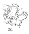
- a known charge air cooler bypass assembly for a turbocharged diesel engined vehicle is illustrated in Fig.1.
- the assembly comprises a manifold 1 having a first gas inlet 2 for connection to an outlet passage of a turbocharger, a first gas outlet 3 for connection to a delivery pipe of the charge air cooler, a second gas inlet 4 for connection to a return pipe from the charge air cooler and a second gas outlet 5 for connection to an intake pipe of the engine.
- a first valve 6, typically comprising a butterfly valve is located in the manifold between the first gas inlet 2 and the first gas outlet 3 and a second valve 7, again typically comprising a butterfly valve, is located in a bypass passage between the first gas inlet 2 and the second gas outlet 4.
- a first rotary actuator 8, such as an electric motor, is provided for actuating the first valve 6 and a second rotary actuator 9 is provided for actuating the second valve 7.
- the first valve 6 is open and the second valve 7 is closed so that charge air passes through the manifold 1 from the compressor of the turbocharger via the first gas inlet 2 and the first has outlet 3 and through the charge air cooler wherein it is cooled before passing back through the manifold 1 and into the air intake of the engine via the second gas inlet 4 and the second gas outlet 5.
- the first valve 6 is closed and the second valve 7 is opened so that the charge air passes directly from the turbocharger to the engine via the first gas inlet 2, the bypass passage and the second gas outlet 5, bypassing the charge air cooler, therefore increasing the temperature of the charge air and thus the temperature of the exhaust gases exiting the combustion chambers of the engine.
- the improved bypass assembly comprises a manifold 1 having a first gas inlet 2 for connection to an outlet passage of a turbocharger, a first gas outlet 3 for connection to a delivery pipe of the charge air cooler, a second gas inlet 4 for connection to a return pipe from the charge air cooler and a second gas outlet 5 for connection to an intake pipe of the engine.
- the first gas inlet 2 is provided at an outer end of a first passageway 10.
- the first gas outlet 3 is provided at an outer end of a second passageway 11.
- the second gas inlet 4 is provided at an outer end of a third passageway 12 and the second gas outlet is provided at an outer end of a fourth gas passageway 13.
- a butterfly valve assembly 20 is provided within the manifold 1 for selectively controlling the flow of gases from the first gas inlet 2 and first passageway 10 into either the first gas outlet 3 and second passageway 11, and hence through the charge air cooler, or into the second gas outlet 5 and passageway 13, and hence directly into the engine, bypassing the charge air cooler.
- the butterfly valve assembly 20 comprises a cylindrical valve housing 22 located between the second passageway 11 and the fourth passageway 13, a circular flap 24 being pivotally mounted within the housing 22 for rotation about a central pivot axis 26 extending perpendicular to the axis of the cylindrical housing 22 between first and second operative positions, the peripheral edge of the flap 24 engaging the inner surface of the housing 22 in each of its operative positions.
- a region 14 of the third passageway 12 defines a convergence between the third passageway 12, the valve housing 22 and the fourth passageway 13 to enable gas from either the valve housing 22 or the third passageway 12 to pass into the fourth passageway 14 and hence the second gas outlet 5.
- the flap 24 of the valve assembly is mechanically connected to an output shaft of a rotary actuator 30, by means of suitable gearing and/or linkages, whereby the flap 24 can be moved between its respective operative positions.
- the actuator is advantageously arranged between the second and third passageways 11,12, the second 11, third 12 and fourth 12 passageways being substantially arranged in a "Y" configuration, to reduce the overall size of the bypass assembly.
- the flow is directed either to the cooler inlet or directly to the gas outlet using one flap.
- the pressure/flow or gas through the valve does not influence the force/torque needed to actuate the mechanism.
- the sealing between the flap and the tube is guaranteed in both positions.
- the pivot axis 26 of the flap 24 is positioned perpendicularly to the axis of the cylindrical valve housing 22.
- the axis 26 is centred on the flap 24.
- the first passageway 10 defines a second cylinder is intersecting the cylindrical valve housing 22 in a zone not interfering with the sealing surface of the housing 22 and the flap 24.
- the flap 24 has a dual profile allowing the flap 24 to seal against the cylindrical housing 22 in both operative positions.
Applications Claiming Priority (1)
| Application Number | Priority Date | Filing Date | Title |
|---|---|---|---|
| GBGB0622555.1A GB0622555D0 (en) | 2006-11-14 | 2006-11-14 | Bypass assembly for a charge-air cooler |
Publications (2)
| Publication Number | Publication Date |
|---|---|
| EP1923550A2 true EP1923550A2 (fr) | 2008-05-21 |
| EP1923550A3 EP1923550A3 (fr) | 2012-10-03 |
Family
ID=37594794
Family Applications (1)
| Application Number | Title | Priority Date | Filing Date |
|---|---|---|---|
| EP07120237A Withdrawn EP1923550A3 (fr) | 2006-11-14 | 2007-11-08 | Ensemble de dérivation pour un refroidisseur d'air de charge |
Country Status (2)
| Country | Link |
|---|---|
| EP (1) | EP1923550A3 (fr) |
| GB (1) | GB0622555D0 (fr) |
Cited By (2)
| Publication number | Priority date | Publication date | Assignee | Title |
|---|---|---|---|---|
| FR2955620A1 (fr) * | 2010-01-26 | 2011-07-29 | Peugeot Citroen Automobiles Sa | Raccord, boitier de derivation pour ce raccord, systeme de refroidissement et vehicule equipe de ce raccord |
| WO2017174121A1 (fr) * | 2016-04-06 | 2017-10-12 | Pierburg Gmbh | Dispositif de vanne de gaz d'échappement |
Citations (2)
| Publication number | Priority date | Publication date | Assignee | Title |
|---|---|---|---|---|
| FR2846407A1 (fr) * | 2002-10-28 | 2004-04-30 | Valeo Thermique Moteur Sa | Echangeur de chaleur a regulation de flux, en particulier pour vehicules automobiles |
| FR2857417A1 (fr) * | 2003-07-07 | 2005-01-14 | Renault Sa | Circuit d'admission pour moteur suralimente a filtre a particules |
-
2006
- 2006-11-14 GB GBGB0622555.1A patent/GB0622555D0/en not_active Ceased
-
2007
- 2007-11-08 EP EP07120237A patent/EP1923550A3/fr not_active Withdrawn
Patent Citations (2)
| Publication number | Priority date | Publication date | Assignee | Title |
|---|---|---|---|---|
| FR2846407A1 (fr) * | 2002-10-28 | 2004-04-30 | Valeo Thermique Moteur Sa | Echangeur de chaleur a regulation de flux, en particulier pour vehicules automobiles |
| FR2857417A1 (fr) * | 2003-07-07 | 2005-01-14 | Renault Sa | Circuit d'admission pour moteur suralimente a filtre a particules |
Cited By (2)
| Publication number | Priority date | Publication date | Assignee | Title |
|---|---|---|---|---|
| FR2955620A1 (fr) * | 2010-01-26 | 2011-07-29 | Peugeot Citroen Automobiles Sa | Raccord, boitier de derivation pour ce raccord, systeme de refroidissement et vehicule equipe de ce raccord |
| WO2017174121A1 (fr) * | 2016-04-06 | 2017-10-12 | Pierburg Gmbh | Dispositif de vanne de gaz d'échappement |
Also Published As
| Publication number | Publication date |
|---|---|
| GB0622555D0 (en) | 2006-12-20 |
| EP1923550A3 (fr) | 2012-10-03 |
Similar Documents
| Publication | Publication Date | Title |
|---|---|---|
| CN109072770B (zh) | 用于废气涡轮增压器的带双通道涡轮机壳体和用于通道连接的阀的涡轮机 | |
| EP2558752B1 (fr) | Soupape multifonction | |
| EP1923551A2 (fr) | Ensemble de dérivation pour un refroidisseur d'air de charge comportant deux éléments de vanne | |
| JP4995259B2 (ja) | 一体型給気およびegr弁 | |
| CA2402284C (fr) | Turbocompresseur dote d'une soupape de recirculation des gaz de carter (egr) | |
| US20150322856A1 (en) | Multi-stage turbocharger system | |
| US20030230085A1 (en) | Exhaust gas turbocharger, supercharged internal combustion engine and method of operation | |
| EP2312146A1 (fr) | Module de papillon de gaz d'echappement/valve de recirculation des gaz d'echappement pour moteur diesel | |
| US8448626B2 (en) | Exhaust system for engine braking | |
| EP2143905A1 (fr) | Ensemble de régulation de soupape | |
| WO2007098133A1 (fr) | Carter de compresseur de turbocompresseur avec etrangleur integre et systeme de derivation et de recyclage | |
| EP2295769A1 (fr) | Système d'échappement pour frein de moteur | |
| KR101695581B1 (ko) | 부스터를 포함하는 내연기관 | |
| JP5986578B2 (ja) | エグゾーストターボチャージャのタービン | |
| EP1336736A2 (fr) | Refroidisseur pour un moteur | |
| US20160032871A1 (en) | Low pressure exhaust gas recirculation module | |
| CN109154229B (zh) | 用于废气涡轮增压器的涡轮机 | |
| US20130309106A1 (en) | Turbocharger | |
| US6564554B2 (en) | Method and apparatus to control a turbocharger wastegate using exhaust pressure | |
| EP3587762A2 (fr) | Turbocompresseur à plusieurs étages avec dérivation à un système de post-traitement | |
| US10683795B2 (en) | Turbine for an exhaust turbocharger having a dual branch turbine housing and valve arrangement for branch connection and waste gate control | |
| WO2007089737A1 (fr) | Combinaison de compresseur a geometrie variable, robinet d'etranglement, et robinet de recirculation | |
| EP1996811B1 (fr) | Module rge basse pression à deux composants | |
| EP1923550A2 (fr) | Ensemble de dérivation pour un refroidisseur d'air de charge | |
| CN111164286B (zh) | 用于机动车的内燃机和具有这种内燃机的机动车 |
Legal Events
| Date | Code | Title | Description |
|---|---|---|---|
| PUAI | Public reference made under article 153(3) epc to a published international application that has entered the european phase |
Free format text: ORIGINAL CODE: 0009012 |
|
| AK | Designated contracting states |
Kind code of ref document: A2 Designated state(s): AT BE BG CH CY CZ DE DK EE ES FI FR GB GR HU IE IS IT LI LT LU LV MC MT NL PL PT RO SE SI SK TR |
|
| AX | Request for extension of the european patent |
Extension state: AL BA HR MK RS |
|
| PUAL | Search report despatched |
Free format text: ORIGINAL CODE: 0009013 |
|
| AK | Designated contracting states |
Kind code of ref document: A3 Designated state(s): AT BE BG CH CY CZ DE DK EE ES FI FR GB GR HU IE IS IT LI LT LU LV MC MT NL PL PT RO SE SI SK TR |
|
| AX | Request for extension of the european patent |
Extension state: AL BA HR MK RS |
|
| RIC1 | Information provided on ipc code assigned before grant |
Ipc: F02B 29/04 20060101AFI20120824BHEP |
|
| AKY | No designation fees paid | ||
| REG | Reference to a national code |
Ref country code: DE Ref legal event code: R108 |
|
| REG | Reference to a national code |
Ref country code: DE Ref legal event code: R108 Effective date: 20130612 |
|
| STAA | Information on the status of an ep patent application or granted ep patent |
Free format text: STATUS: THE APPLICATION IS DEEMED TO BE WITHDRAWN |
|
| 18D | Application deemed to be withdrawn |
Effective date: 20130404 |