EP1923550A2 - Bypass assembly for a charge-air cooler - Google Patents
Bypass assembly for a charge-air cooler Download PDFInfo
- Publication number
- EP1923550A2 EP1923550A2 EP07120237A EP07120237A EP1923550A2 EP 1923550 A2 EP1923550 A2 EP 1923550A2 EP 07120237 A EP07120237 A EP 07120237A EP 07120237 A EP07120237 A EP 07120237A EP 1923550 A2 EP1923550 A2 EP 1923550A2
- Authority
- EP
- European Patent Office
- Prior art keywords
- passageway
- gas
- inlet
- gas outlet
- outlet
- Prior art date
- Legal status (The legal status is an assumption and is not a legal conclusion. Google has not performed a legal analysis and makes no representation as to the accuracy of the status listed.)
- Withdrawn
Links
Images

Classifications
-
- F—MECHANICAL ENGINEERING; LIGHTING; HEATING; WEAPONS; BLASTING
- F02—COMBUSTION ENGINES; HOT-GAS OR COMBUSTION-PRODUCT ENGINE PLANTS
- F02B—INTERNAL-COMBUSTION PISTON ENGINES; COMBUSTION ENGINES IN GENERAL
- F02B29/00—Engines characterised by provision for charging or scavenging not provided for in groups F02B25/00, F02B27/00 or F02B33/00 - F02B39/00; Details thereof
- F02B29/04—Cooling of air intake supply
- F02B29/0406—Layout of the intake air cooling or coolant circuit
- F02B29/0418—Layout of the intake air cooling or coolant circuit the intake air cooler having a bypass or multiple flow paths within the heat exchanger to vary the effective heat transfer surface
-
- F—MECHANICAL ENGINEERING; LIGHTING; HEATING; WEAPONS; BLASTING
- F02—COMBUSTION ENGINES; HOT-GAS OR COMBUSTION-PRODUCT ENGINE PLANTS
- F02B—INTERNAL-COMBUSTION PISTON ENGINES; COMBUSTION ENGINES IN GENERAL
- F02B33/00—Engines characterised by provision of pumps for charging or scavenging
- F02B33/44—Passages conducting the charge from the pump to the engine inlet, e.g. reservoirs
-
- F—MECHANICAL ENGINEERING; LIGHTING; HEATING; WEAPONS; BLASTING
- F02—COMBUSTION ENGINES; HOT-GAS OR COMBUSTION-PRODUCT ENGINE PLANTS
- F02B—INTERNAL-COMBUSTION PISTON ENGINES; COMBUSTION ENGINES IN GENERAL
- F02B37/00—Engines characterised by provision of pumps driven at least for part of the time by exhaust
-
- Y—GENERAL TAGGING OF NEW TECHNOLOGICAL DEVELOPMENTS; GENERAL TAGGING OF CROSS-SECTIONAL TECHNOLOGIES SPANNING OVER SEVERAL SECTIONS OF THE IPC; TECHNICAL SUBJECTS COVERED BY FORMER USPC CROSS-REFERENCE ART COLLECTIONS [XRACs] AND DIGESTS
- Y02—TECHNOLOGIES OR APPLICATIONS FOR MITIGATION OR ADAPTATION AGAINST CLIMATE CHANGE
- Y02T—CLIMATE CHANGE MITIGATION TECHNOLOGIES RELATED TO TRANSPORTATION
- Y02T10/00—Road transport of goods or passengers
- Y02T10/10—Internal combustion engine [ICE] based vehicles
- Y02T10/12—Improving ICE efficiencies
Definitions
- the present invention relates to a bypass assembly for a charge air cooler of an internal combustion engine.
- the amount of air which can be supplied to an internal combustion engine in a vehicle depends on the pressure of the air but also on the temperature of the air. While performance gains can be obtained by compressing air downstream of the intake manifold of an engine using a turbocharger or a supercharger, supplying the largest possible amount of air to an internal combustion engine entails cooling the compressed air in a charge air cooler downstream of the compressor of the turbocharger or supercharger before it is led to the combustion chamber of the engine. Therefore a charge air cooler is typically provided downstream of the turbocharger or compressor, usually situated in front of the conventional radiator in a vehicle to enable heat exchange between the compressed charge air and a flow of ambient air through the cooler to cool the compressed air.
- Diesel engines are frequently fitted with particulate filters in the exhaust system thereof due to the demands of emission legislation.
- filters are usually mounted in the exhaust system downstream of a catalytic device such as an oxidation catalyst and other exhaust components, such as a turbocharger.
- particulate filters require periodic regeneration. During regeneration the temperature of the filter is increased so that the accumulated soot is burnt off, thereby ensuring both acceptable back pressure levels and the avoidance of filter overload.
- This periodic regeneration process requires the temperature of the particulate filter to be greatly elevated.
- the temperature of the particulate filter must be raised to around 600°C in order to burn off the soot, compared to a normal exhaust operating temperature of 150°C.
- the body further comprises a second gas inlet passageway having an inlet for communication with an outlet of a charge air cooler, said second gas inlet passageway communicating with said second gas outlet passageway.
- the valve means comprises a valve member pivotally mounted in a passage section located between the first gas outlet passageway and the second gas outlet passageway, the valve member having a pivot axis arranged normal to the longitudinal axis of said passage section such that peripheral edge regions of the valve member are engageable against respective inner surfaces of the passage section when in its first and second configurations, said first gas inlet passageway intersecting said passage section in a direction substantially normal to the pivot axis of the valve member and at a location between said respective inner surfaces of the cylindrical region cooperating with said valve member when in its respective first and second configuration.
- said first gas inlet passageway at least in the region of the valve means, extends perpendicular to said passage section.
- said passage section is substantially cylindrical and said valve member comprises a substantially circular flap having a central diametrically extending pivot axis extending radially through a centre of the passage section.
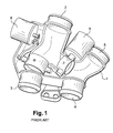
- a known charge air cooler bypass assembly for a turbocharged diesel engined vehicle is illustrated in Fig.1.
- the assembly comprises a manifold 1 having a first gas inlet 2 for connection to an outlet passage of a turbocharger, a first gas outlet 3 for connection to a delivery pipe of the charge air cooler, a second gas inlet 4 for connection to a return pipe from the charge air cooler and a second gas outlet 5 for connection to an intake pipe of the engine.
- a first valve 6, typically comprising a butterfly valve is located in the manifold between the first gas inlet 2 and the first gas outlet 3 and a second valve 7, again typically comprising a butterfly valve, is located in a bypass passage between the first gas inlet 2 and the second gas outlet 4.
- a first rotary actuator 8, such as an electric motor, is provided for actuating the first valve 6 and a second rotary actuator 9 is provided for actuating the second valve 7.
- the first valve 6 is open and the second valve 7 is closed so that charge air passes through the manifold 1 from the compressor of the turbocharger via the first gas inlet 2 and the first has outlet 3 and through the charge air cooler wherein it is cooled before passing back through the manifold 1 and into the air intake of the engine via the second gas inlet 4 and the second gas outlet 5.
- the first valve 6 is closed and the second valve 7 is opened so that the charge air passes directly from the turbocharger to the engine via the first gas inlet 2, the bypass passage and the second gas outlet 5, bypassing the charge air cooler, therefore increasing the temperature of the charge air and thus the temperature of the exhaust gases exiting the combustion chambers of the engine.
- the improved bypass assembly comprises a manifold 1 having a first gas inlet 2 for connection to an outlet passage of a turbocharger, a first gas outlet 3 for connection to a delivery pipe of the charge air cooler, a second gas inlet 4 for connection to a return pipe from the charge air cooler and a second gas outlet 5 for connection to an intake pipe of the engine.
- the first gas inlet 2 is provided at an outer end of a first passageway 10.
- the first gas outlet 3 is provided at an outer end of a second passageway 11.
- the second gas inlet 4 is provided at an outer end of a third passageway 12 and the second gas outlet is provided at an outer end of a fourth gas passageway 13.
- a butterfly valve assembly 20 is provided within the manifold 1 for selectively controlling the flow of gases from the first gas inlet 2 and first passageway 10 into either the first gas outlet 3 and second passageway 11, and hence through the charge air cooler, or into the second gas outlet 5 and passageway 13, and hence directly into the engine, bypassing the charge air cooler.
- the butterfly valve assembly 20 comprises a cylindrical valve housing 22 located between the second passageway 11 and the fourth passageway 13, a circular flap 24 being pivotally mounted within the housing 22 for rotation about a central pivot axis 26 extending perpendicular to the axis of the cylindrical housing 22 between first and second operative positions, the peripheral edge of the flap 24 engaging the inner surface of the housing 22 in each of its operative positions.
- a region 14 of the third passageway 12 defines a convergence between the third passageway 12, the valve housing 22 and the fourth passageway 13 to enable gas from either the valve housing 22 or the third passageway 12 to pass into the fourth passageway 14 and hence the second gas outlet 5.
- the flap 24 of the valve assembly is mechanically connected to an output shaft of a rotary actuator 30, by means of suitable gearing and/or linkages, whereby the flap 24 can be moved between its respective operative positions.
- the actuator is advantageously arranged between the second and third passageways 11,12, the second 11, third 12 and fourth 12 passageways being substantially arranged in a "Y" configuration, to reduce the overall size of the bypass assembly.
- the flow is directed either to the cooler inlet or directly to the gas outlet using one flap.
- the pressure/flow or gas through the valve does not influence the force/torque needed to actuate the mechanism.
- the sealing between the flap and the tube is guaranteed in both positions.
- the pivot axis 26 of the flap 24 is positioned perpendicularly to the axis of the cylindrical valve housing 22.
- the axis 26 is centred on the flap 24.
- the first passageway 10 defines a second cylinder is intersecting the cylindrical valve housing 22 in a zone not interfering with the sealing surface of the housing 22 and the flap 24.
- the flap 24 has a dual profile allowing the flap 24 to seal against the cylindrical housing 22 in both operative positions.
Abstract
Description
- The present invention relates to a bypass assembly for a charge air cooler of an internal combustion engine.
- The amount of air which can be supplied to an internal combustion engine in a vehicle depends on the pressure of the air but also on the temperature of the air. While performance gains can be obtained by compressing air downstream of the intake manifold of an engine using a turbocharger or a supercharger, supplying the largest possible amount of air to an internal combustion engine entails cooling the compressed air in a charge air cooler downstream of the compressor of the turbocharger or supercharger before it is led to the combustion chamber of the engine. Therefore a charge air cooler is typically provided downstream of the turbocharger or compressor, usually situated in front of the conventional radiator in a vehicle to enable heat exchange between the compressed charge air and a flow of ambient air through the cooler to cool the compressed air.
- Diesel engines are frequently fitted with particulate filters in the exhaust system thereof due to the demands of emission legislation. Such filters are usually mounted in the exhaust system downstream of a catalytic device such as an oxidation catalyst and other exhaust components, such as a turbocharger.
- In order to avoid blockage of the particulate filter by accumulated soot, leading to an increase in exhaust backpressure, and ultimately a breakdown of the filter, particulate filters require periodic regeneration. During regeneration the temperature of the filter is increased so that the accumulated soot is burnt off, thereby ensuring both acceptable back pressure levels and the avoidance of filter overload.
- This periodic regeneration process requires the temperature of the particulate filter to be greatly elevated. The temperature of the particulate filter must be raised to around 600°C in order to burn off the soot, compared to a normal exhaust operating temperature of 150°C.
- One way to increase the temperature of the particulate filter to achieve regeneration of the filter is to increase the temperature of the exhaust gases leaving the combustion chamber(s) of the engine. This can be achieved by increasing the temperature of the charge air entering the combustion chamber(s) by passing charge air directly from the compressor of the turbocharger or super charger to the inlet manifold, bypassing the charge air cooler. In order to achieve such selective bypass of the charge air cooler, it is known to provide valve arrangements for closing the inlet passage of the charge air cooler and opening a bypass passage between the compressor and the inlet manifold. Such known arrangements include multiple valve and multiple valve actuators, leading to increased cost and complexity.
- According to the present invention there is provided a bypass assembly for a charge air cooler of an internal combustion engine comprising a body having a first gas inlet passageway having an inlet for communication with a charge air outlet of a turbocharger or supercharger, a first gas outlet passageway having an outlet for communication with an inlet of a charge air cooler, and a second gas outlet passageway having an outlet for communication with an inlet manifold of the engine, a valve means being mounted within the body at an intersection of said first gas inlet passageway, said first gas outlet passageway and said second gas outlet passageway, said valve means having a first configuration, enabling gas flow between said first gas inlet passageway and said first gas outlet passageway and preventing communication between said first gas inlet passageway and said second gas outlet passageway, and a second configuration enabling gas flow between said first gas inlet passageway and said second gas outlet passageway and preventing communication between said first gas inlet passageway and said first gas outlet passageway, actuator means being provided for moving said valve means between its first and second configurations.
- Preferably the body further comprises a second gas inlet passageway having an inlet for communication with an outlet of a charge air cooler, said second gas inlet passageway communicating with said second gas outlet passageway.
- In one embodiment the valve means comprises a valve member pivotally mounted in a passage section located between the first gas outlet passageway and the second gas outlet passageway, the valve member having a pivot axis arranged normal to the longitudinal axis of said passage section such that peripheral edge regions of the valve member are engageable against respective inner surfaces of the passage section when in its first and second configurations, said first gas inlet passageway intersecting said passage section in a direction substantially normal to the pivot axis of the valve member and at a location between said respective inner surfaces of the cylindrical region cooperating with said valve member when in its respective first and second configuration. Preferably said first gas inlet passageway, at least in the region of the valve means, extends perpendicular to said passage section.
- Preferably said passage section is substantially cylindrical and said valve member comprises a substantially circular flap having a central diametrically extending pivot axis extending radially through a centre of the passage section.
- An embodiment of the present invention will now be described by way of example only with reference to the accompanying drawings, in which:
- Fig. 1 is a part sectional perspective view of a known bypass assembly.
- Fig. 2 is a part sectional perspective view of a bypass assembly according to an embodiment of the present invention.
- A known charge air cooler bypass assembly for a turbocharged diesel engined vehicle is illustrated in Fig.1. The assembly comprises a
manifold 1 having afirst gas inlet 2 for connection to an outlet passage of a turbocharger, afirst gas outlet 3 for connection to a delivery pipe of the charge air cooler, asecond gas inlet 4 for connection to a return pipe from the charge air cooler and asecond gas outlet 5 for connection to an intake pipe of the engine. Afirst valve 6, typically comprising a butterfly valve, is located in the manifold between thefirst gas inlet 2 and thefirst gas outlet 3 and asecond valve 7, again typically comprising a butterfly valve, is located in a bypass passage between thefirst gas inlet 2 and thesecond gas outlet 4. A firstrotary actuator 8, such as an electric motor, is provided for actuating thefirst valve 6 and a secondrotary actuator 9 is provided for actuating thesecond valve 7. - During normal engine operation the
first valve 6 is open and thesecond valve 7 is closed so that charge air passes through themanifold 1 from the compressor of the turbocharger via thefirst gas inlet 2 and the first hasoutlet 3 and through the charge air cooler wherein it is cooled before passing back through themanifold 1 and into the air intake of the engine via thesecond gas inlet 4 and thesecond gas outlet 5. When it is desired to regenerate the particulate filter contained in the exhaust system of the vehicle, thefirst valve 6 is closed and thesecond valve 7 is opened so that the charge air passes directly from the turbocharger to the engine via thefirst gas inlet 2, the bypass passage and thesecond gas outlet 5, bypassing the charge air cooler, therefore increasing the temperature of the charge air and thus the temperature of the exhaust gases exiting the combustion chambers of the engine. - As can be seen from Fig. 1, the requirement for two separate valve and two separate actuators increases the size of the bypass assembly. Furthermore, the use of two separate actuators requires complex control systems to synchronise the operation of the two valves.
- An embodiment of the present invention is shown in Fig. 2. Like reference numerals are used for like parts to aid understanding. The improved bypass assembly comprises a
manifold 1 having afirst gas inlet 2 for connection to an outlet passage of a turbocharger, afirst gas outlet 3 for connection to a delivery pipe of the charge air cooler, asecond gas inlet 4 for connection to a return pipe from the charge air cooler and asecond gas outlet 5 for connection to an intake pipe of the engine. - The
first gas inlet 2 is provided at an outer end of afirst passageway 10. Thefirst gas outlet 3 is provided at an outer end of asecond passageway 11. Thesecond gas inlet 4 is provided at an outer end of athird passageway 12 and the second gas outlet is provided at an outer end of afourth gas passageway 13. - A
butterfly valve assembly 20 is provided within themanifold 1 for selectively controlling the flow of gases from thefirst gas inlet 2 andfirst passageway 10 into either thefirst gas outlet 3 andsecond passageway 11, and hence through the charge air cooler, or into thesecond gas outlet 5 andpassageway 13, and hence directly into the engine, bypassing the charge air cooler. - The
butterfly valve assembly 20 comprises acylindrical valve housing 22 located between thesecond passageway 11 and thefourth passageway 13, acircular flap 24 being pivotally mounted within thehousing 22 for rotation about acentral pivot axis 26 extending perpendicular to the axis of thecylindrical housing 22 between first and second operative positions, the peripheral edge of theflap 24 engaging the inner surface of thehousing 22 in each of its operative positions. - A
region 14 of thethird passageway 12 defines a convergence between thethird passageway 12, thevalve housing 22 and thefourth passageway 13 to enable gas from either thevalve housing 22 or thethird passageway 12 to pass into thefourth passageway 14 and hence thesecond gas outlet 5. - The
first passageway 10 intersects and opens into thecylindrical valve housing 22 in a direction normal to the axis of thecylindrical housing 22 and perpendicular to thepivot axis 26 of theflap 24. The relative dimensions of thehousing 22,flap 24 andfirst passageway 10 are selected such that opening of thefirst passageway 10 into thecylindrical housing 22 falls within a boundary defined by the contact points of the peripheral edge of theflap 24 with the inner surface of thehousing 22 in each of its operative positions. - The
flap 24 of the valve assembly is mechanically connected to an output shaft of arotary actuator 30, by means of suitable gearing and/or linkages, whereby theflap 24 can be moved between its respective operative positions. - The by-pass valve has two operative positions:
- a) a first operative position (normal mode as shown in Fig. 2) wherein the hot air flow from the turbo-charger passes through the manifold via the
first gas inlet 2,first passageway 10, through the valve housing and into thesecond passageway 11 and through thefirst gas outlet 3 to pass through the charge air cooler before being passed to the intake manifold of the engine via thesecond gas inlet 4,second passageway 12,third passageway 13 and through thesecond gas outlet 5; - b) a second operative position (particle filter regeneration - with the flap valve rotated substantially 90° in a counter-clockwise direction from its position shown in Fig. 2) wherein the hot air flow from the turbo charger is passed directly to the intake manifold of the engine via the
first gas inlet 2,first passageway 10,valve housing 22,fourth passageway 13 andsecond gas outlet 5, bypassing the charge air cooler. - The actuator is advantageously arranged between the second and
third passageways - Previous valves were using two independent actuators and two mechanisms. The novelty of this invention is to have only one valve and a single actuator.
- The flow is directed either to the cooler inlet or directly to the gas outlet using one flap. The pressure/flow or gas through the valve does not influence the force/torque needed to actuate the mechanism. The sealing between the flap and the tube is guaranteed in both positions.
- The
pivot axis 26 of theflap 24 is positioned perpendicularly to the axis of thecylindrical valve housing 22. Theaxis 26 is centred on theflap 24. Thefirst passageway 10 defines a second cylinder is intersecting thecylindrical valve housing 22 in a zone not interfering with the sealing surface of thehousing 22 and theflap 24. - The
flap 24 has a dual profile allowing theflap 24 to seal against thecylindrical housing 22 in both operative positions.
Claims (6)
- A bypass assembly for a charge air cooler of an internal combustion engine comprising a body having a first gas inlet (2) passageway having an inlet for communication with a charge air outlet of a turbocharger or supercharger, a first gas outlet (3) passageway having an outlet for communication with an inlet of a charge air cooler, and a second gas outlet (5) passageway having an outlet for communication with an inlet manifold of the engine, a valve means (20) being mounted within the body,
characterized in that said valve means (20) is mounted at an intersection of said first gas inlet (2) passageway, said first gas outlet (3) passageway and said second gas outlet (5) passageway, said valve means (20) having a first configuration, enabling gas flow between said first gas inlet (2) passageway and said first gas outlet (3) passageway and preventing communication between said first gas inlet (2) passageway and said second gas outlet (5) passageway, and a second configuration enabling gas flow between said first gas inlet (2) passageway and said second gas outlet (5) passageway and preventing communication between said first gas inlet (2) passageway and said first gas outlet (3) passageway, actuator means (30) being provided for moving said valve means (20) between its first and second configurations. - The bypass assembly according to claim 1, characterized in that the body further comprises a second gas inlet (4) passageway having an inlet for communication with an outlet of a charge air cooler, said second gas inlet (4) passageway communicating with said second gas outlet (5) passageway.
- The bypass assembly according to claim 1 or 2, characterized in that the valve means (20) comprises a valve member (24) pivotally mounted in a passage section (22) located between the first gas outlet (3) passageway and the second gas outlet (5) passageway, the valve member (24) having a pivot axis (26) arranged normal to the longitudinal axis of said passage section (22) such that peripheral edge regions of the valve member (24) are engageable against respective inner surfaces of the passage section (22) when in its first and second configurations.
- The bypass assembly according to claim 3, characterized in that said first gas inlet (2) passageway intersects said passage section (22) in a direction substantially normal to the pivot axis (26) of the valve member (24) and at a location between said respective inner surfaces of the cylindrical region cooperating with said valve member (24) when in its respective first and second configuration.
- The bypass assembly according to claim 3 or 4, characterized in that said first gas inlet (2) passageway extends perpendicular to said passage section (22) at least in the region of the valve means (20).
- The bypass assembly according to anyone of claims 3 to 5, characterized in that said passage section (22) is substantially cylindrical and said valve member (24) comprises a substantially circular flap having a central diametrically extending pivot axis (26) extending radially through a centre of the passage section (22).
Applications Claiming Priority (1)
| Application Number | Priority Date | Filing Date | Title |
|---|---|---|---|
| GBGB0622555.1A GB0622555D0 (en) | 2006-11-14 | 2006-11-14 | Bypass assembly for a charge-air cooler |
Publications (2)
| Publication Number | Publication Date |
|---|---|
| EP1923550A2 true EP1923550A2 (en) | 2008-05-21 |
| EP1923550A3 EP1923550A3 (en) | 2012-10-03 |
Family
ID=37594794
Family Applications (1)
| Application Number | Title | Priority Date | Filing Date |
|---|---|---|---|
| EP07120237A Withdrawn EP1923550A3 (en) | 2006-11-14 | 2007-11-08 | Bypass assembly for a charge-air cooler |
Country Status (2)
| Country | Link |
|---|---|
| EP (1) | EP1923550A3 (en) |
| GB (1) | GB0622555D0 (en) |
Cited By (2)
| Publication number | Priority date | Publication date | Assignee | Title |
|---|---|---|---|---|
| FR2955620A1 (en) * | 2010-01-26 | 2011-07-29 | Peugeot Citroen Automobiles Sa | Preassembled connector for air supercharging cooling system in e.g. car, to supercharge air cooler, has side outlet case deviating portion of supercharging air to encircle hoses and directing supercharging air towards intake hose |
| WO2017174121A1 (en) * | 2016-04-06 | 2017-10-12 | Pierburg Gmbh | Exhaust gas valve device |
Citations (2)
| Publication number | Priority date | Publication date | Assignee | Title |
|---|---|---|---|---|
| FR2846407A1 (en) * | 2002-10-28 | 2004-04-30 | Valeo Thermique Moteur Sa | HEAT EXCHANGER WITH FLOW CONTROL, ESPECIALLY FOR MOTOR VEHICLES |
| FR2857417A1 (en) * | 2003-07-07 | 2005-01-14 | Renault Sa | Air intake circuit for internal combustion engine, has distribution chamber with control circuit connecting inputs and outputs in one position and cross connecting inputs and outputs in another position |
-
2006
- 2006-11-14 GB GBGB0622555.1A patent/GB0622555D0/en not_active Ceased
-
2007
- 2007-11-08 EP EP07120237A patent/EP1923550A3/en not_active Withdrawn
Patent Citations (2)
| Publication number | Priority date | Publication date | Assignee | Title |
|---|---|---|---|---|
| FR2846407A1 (en) * | 2002-10-28 | 2004-04-30 | Valeo Thermique Moteur Sa | HEAT EXCHANGER WITH FLOW CONTROL, ESPECIALLY FOR MOTOR VEHICLES |
| FR2857417A1 (en) * | 2003-07-07 | 2005-01-14 | Renault Sa | Air intake circuit for internal combustion engine, has distribution chamber with control circuit connecting inputs and outputs in one position and cross connecting inputs and outputs in another position |
Cited By (2)
| Publication number | Priority date | Publication date | Assignee | Title |
|---|---|---|---|---|
| FR2955620A1 (en) * | 2010-01-26 | 2011-07-29 | Peugeot Citroen Automobiles Sa | Preassembled connector for air supercharging cooling system in e.g. car, to supercharge air cooler, has side outlet case deviating portion of supercharging air to encircle hoses and directing supercharging air towards intake hose |
| WO2017174121A1 (en) * | 2016-04-06 | 2017-10-12 | Pierburg Gmbh | Exhaust gas valve device |
Also Published As
| Publication number | Publication date |
|---|---|
| EP1923550A3 (en) | 2012-10-03 |
| GB0622555D0 (en) | 2006-12-20 |
Similar Documents
| Publication | Publication Date | Title |
|---|---|---|
| CN109072770B (en) | Turbine for an exhaust gas turbocharger with a two-channel turbine housing and a valve for the channel connection | |
| EP2558752B1 (en) | Multifunction valve | |
| EP1923551A2 (en) | Bypass assembly for a charge-air cooler including two valve members | |
| JP4995259B2 (en) | Integrated air supply and EGR valve | |
| CA2402284C (en) | Turbocharger with integrated exhaust gas recirculation valve | |
| US20150322856A1 (en) | Multi-stage turbocharger system | |
| US20030230085A1 (en) | Exhaust gas turbocharger, supercharged internal combustion engine and method of operation | |
| EP2312146A1 (en) | Exhaust throttle-EGR valve module for a diesel engine | |
| US8448626B2 (en) | Exhaust system for engine braking | |
| EP2143905A1 (en) | Valve regulation assembly | |
| WO2007098133A1 (en) | Turbocharger compressor housing with integrated throttle valve and recirculation-bypass system | |
| EP2295769A1 (en) | Exhaust system for engine braking | |
| KR101695581B1 (en) | Internal combustion engine comprising a booster | |
| JP5986578B2 (en) | Exhaust turbocharger turbine | |
| EP1336736A2 (en) | Intercooler for an engine | |
| US20160032871A1 (en) | Low pressure exhaust gas recirculation module | |
| CN109154229B (en) | Turbine for an exhaust-gas turbocharger | |
| US20130309106A1 (en) | Turbocharger | |
| US6564554B2 (en) | Method and apparatus to control a turbocharger wastegate using exhaust pressure | |
| EP3587762A2 (en) | Multi-stage turbocharger with bypass to an aftertreatment system | |
| US10683795B2 (en) | Turbine for an exhaust turbocharger having a dual branch turbine housing and valve arrangement for branch connection and waste gate control | |
| WO2007089737A1 (en) | Combination variable geometry compressor, throttle valve, and recirculation valve | |
| EP1996811B1 (en) | Two component low pressure egr module | |
| EP1923550A2 (en) | Bypass assembly for a charge-air cooler | |
| CN111164286B (en) | Internal combustion engine for a motor vehicle and motor vehicle having such an internal combustion engine |
Legal Events
| Date | Code | Title | Description |
|---|---|---|---|
| PUAI | Public reference made under article 153(3) epc to a published international application that has entered the european phase |
Free format text: ORIGINAL CODE: 0009012 |
|
| AK | Designated contracting states |
Kind code of ref document: A2 Designated state(s): AT BE BG CH CY CZ DE DK EE ES FI FR GB GR HU IE IS IT LI LT LU LV MC MT NL PL PT RO SE SI SK TR |
|
| AX | Request for extension of the european patent |
Extension state: AL BA HR MK RS |
|
| PUAL | Search report despatched |
Free format text: ORIGINAL CODE: 0009013 |
|
| AK | Designated contracting states |
Kind code of ref document: A3 Designated state(s): AT BE BG CH CY CZ DE DK EE ES FI FR GB GR HU IE IS IT LI LT LU LV MC MT NL PL PT RO SE SI SK TR |
|
| AX | Request for extension of the european patent |
Extension state: AL BA HR MK RS |
|
| RIC1 | Information provided on ipc code assigned before grant |
Ipc: F02B 29/04 20060101AFI20120824BHEP |
|
| AKY | No designation fees paid | ||
| REG | Reference to a national code |
Ref country code: DE Ref legal event code: R108 |
|
| REG | Reference to a national code |
Ref country code: DE Ref legal event code: R108 Effective date: 20130612 |
|
| STAA | Information on the status of an ep patent application or granted ep patent |
Free format text: STATUS: THE APPLICATION IS DEEMED TO BE WITHDRAWN |
|
| 18D | Application deemed to be withdrawn |
Effective date: 20130404 |