EP1920809B1 - Neuartiges Verfahren zur Dehydratisierung von Alkohol und Anlage für dessen Umsetzung - Google Patents
Neuartiges Verfahren zur Dehydratisierung von Alkohol und Anlage für dessen Umsetzung Download PDFInfo
- Publication number
- EP1920809B1 EP1920809B1 EP20070291266 EP07291266A EP1920809B1 EP 1920809 B1 EP1920809 B1 EP 1920809B1 EP 20070291266 EP20070291266 EP 20070291266 EP 07291266 A EP07291266 A EP 07291266A EP 1920809 B1 EP1920809 B1 EP 1920809B1
- Authority
- EP
- European Patent Office
- Prior art keywords
- water
- alcohol
- unit
- vapor
- dehydrated alcohol
- Prior art date
- Legal status (The legal status is an assumption and is not a legal conclusion. Google has not performed a legal analysis and makes no representation as to the accuracy of the status listed.)
- Not-in-force
Links
Images


Classifications
-
- C—CHEMISTRY; METALLURGY
- C07—ORGANIC CHEMISTRY
- C07C—ACYCLIC OR CARBOCYCLIC COMPOUNDS
- C07C29/00—Preparation of compounds having hydroxy or O-metal groups bound to a carbon atom not belonging to a six-membered aromatic ring
- C07C29/74—Separation; Purification; Use of additives, e.g. for stabilisation
- C07C29/76—Separation; Purification; Use of additives, e.g. for stabilisation by physical treatment
-
- B—PERFORMING OPERATIONS; TRANSPORTING
- B01—PHYSICAL OR CHEMICAL PROCESSES OR APPARATUS IN GENERAL
- B01D—SEPARATION
- B01D1/00—Evaporating
- B01D1/28—Evaporating with vapour compression
- B01D1/289—Compressor features (e.g. constructions, details, cooling, lubrication, driving systems)
-
- B—PERFORMING OPERATIONS; TRANSPORTING
- B01—PHYSICAL OR CHEMICAL PROCESSES OR APPARATUS IN GENERAL
- B01D—SEPARATION
- B01D3/00—Distillation or related exchange processes in which liquids are contacted with gaseous media, e.g. stripping
- B01D3/001—Processes specially adapted for distillation or rectification of fermented solutions
-
- B—PERFORMING OPERATIONS; TRANSPORTING
- B01—PHYSICAL OR CHEMICAL PROCESSES OR APPARATUS IN GENERAL
- B01D—SEPARATION
- B01D3/00—Distillation or related exchange processes in which liquids are contacted with gaseous media, e.g. stripping
- B01D3/007—Energy recuperation; Heat pumps
-
- B—PERFORMING OPERATIONS; TRANSPORTING
- B01—PHYSICAL OR CHEMICAL PROCESSES OR APPARATUS IN GENERAL
- B01D—SEPARATION
- B01D53/00—Separation of gases or vapours; Recovering vapours of volatile solvents from gases; Chemical or biological purification of waste gases, e.g. engine exhaust gases, smoke, fumes, flue gases, aerosols
- B01D53/26—Drying gases or vapours
- B01D53/261—Drying gases or vapours by adsorption
-
- B—PERFORMING OPERATIONS; TRANSPORTING
- B01—PHYSICAL OR CHEMICAL PROCESSES OR APPARATUS IN GENERAL
- B01D—SEPARATION
- B01D2253/00—Adsorbents used in seperation treatment of gases and vapours
- B01D2253/10—Inorganic adsorbents
- B01D2253/106—Silica or silicates
- B01D2253/108—Zeolites
-
- B—PERFORMING OPERATIONS; TRANSPORTING
- B01—PHYSICAL OR CHEMICAL PROCESSES OR APPARATUS IN GENERAL
- B01D—SEPARATION
- B01D2259/00—Type of treatment
- B01D2259/40—Further details for adsorption processes and devices
- B01D2259/403—Further details for adsorption processes and devices using three beds
-
- Y—GENERAL TAGGING OF NEW TECHNOLOGICAL DEVELOPMENTS; GENERAL TAGGING OF CROSS-SECTIONAL TECHNOLOGIES SPANNING OVER SEVERAL SECTIONS OF THE IPC; TECHNICAL SUBJECTS COVERED BY FORMER USPC CROSS-REFERENCE ART COLLECTIONS [XRACs] AND DIGESTS
- Y02—TECHNOLOGIES OR APPLICATIONS FOR MITIGATION OR ADAPTATION AGAINST CLIMATE CHANGE
- Y02P—CLIMATE CHANGE MITIGATION TECHNOLOGIES IN THE PRODUCTION OR PROCESSING OF GOODS
- Y02P20/00—Technologies relating to chemical industry
- Y02P20/50—Improvements relating to the production of bulk chemicals
-
- Y—GENERAL TAGGING OF NEW TECHNOLOGICAL DEVELOPMENTS; GENERAL TAGGING OF CROSS-SECTIONAL TECHNOLOGIES SPANNING OVER SEVERAL SECTIONS OF THE IPC; TECHNICAL SUBJECTS COVERED BY FORMER USPC CROSS-REFERENCE ART COLLECTIONS [XRACs] AND DIGESTS
- Y02—TECHNOLOGIES OR APPLICATIONS FOR MITIGATION OR ADAPTATION AGAINST CLIMATE CHANGE
- Y02P—CLIMATE CHANGE MITIGATION TECHNOLOGIES IN THE PRODUCTION OR PROCESSING OF GOODS
- Y02P70/00—Climate change mitigation technologies in the production process for final industrial or consumer products
- Y02P70/10—Greenhouse gas [GHG] capture, material saving, heat recovery or other energy efficient measures, e.g. motor control, characterised by manufacturing processes, e.g. for rolling metal or metal working
Definitions
- the present invention relates to a new method of alcohol dehydration by adsorption on molecular sieve, which offers energy savings over existing processes and facilities.
- the invention also relates to the implementation of the new method according to the invention.
- the TSA method makes use of the fact that the quantities of adsorbed gas decrease when the temperature increases, for a given pressure.
- a stream of hot gaseous fluid, air or inert gas is sent to the flask containing the sieve. This has the effect of driving the adsorbed product to the inlet of the column.
- the PSA process relies on the fact that desorption can be achieved by applying a large pressure drop.
- This second method is mainly used in the field of purification of industrial gases.
- the TSA process is not easily transposable to the dehydration of alcohols because it requires the use of gases, such as nitrogen, argon, carbon dioxide and others, which are then released into the atmosphere. This therefore implies the presence of storage tanks, which are expensive and has inherent problems storage tanks, including security.
- the document FR 2,719,039 still proposes an improvement over the above process, consisting of the addition, before step (iii) of regeneration, of an additional step of overheating the part of the ethanol dehydrated to pass over the molecular sieve to desorb the adsorbed water.
- This improvement allows for increased control of desorption and a reduction in the amount of dehydrated ethanol required for the desorption phase (from about 20 to about 15%).
- the document CA 2,503,067 discloses a system for producing dehydrated alcohol from plants in which energy coupling is provided between the alcohol dehydration unit itself and other units of the system.
- the level of energy consumption of all the processes of the prior art described above remains problematic, in particular if it is considered that the dehydrated alcohol is mainly intended for the production of alcohol fuel, which is in competition with petroleum refining processes. It is therefore desirable to achieve further optimization of the primary energy consumption of industrial processes of dehydrated alcohol production and in particular to achieve optimum energy consumption specifically at the level of the alcohol dehydration unit.
- the alcohol is ethanol.
- the water / alcohol mixture contains at least 80% by volume of alcohol, preferably at least 90% by volume of alcohol, preferably at least 92% by volume of alcohol.
- the method according to the invention comprises in step (iv) an overheating of the portion of the dehydrated alcohol to pass over the molecular sieve saturated with water to desorb the adsorbed water.
- the effluent obtained in step (iv) is combined with the water / alcohol mixture to be treated.
- two, three or more molecular sieves operate in an alternating mode.
- the process according to the invention requires a water vapor consumption of less than about 50 kg per 100 liters of dehydrated alcohol produced.
- the vaporization unit comprises a distillation column.
- the condensation unit is provided for evaporating the water / alcohol mixture directly at the level of the vaporization unit.
- the installation according to the invention further comprises a heat exchanger providing part of the power supply of the vaporization unit.
- the plant according to the invention further comprises a recycling line for recycling the effluent to the vaporization unit.
- the plant according to the invention further comprises a recycling line for recycling the effluent to a distillation unit supplying steam a heat exchanger intended to supply energy to the unit of heat. vaporization.
- the installation according to the invention further comprises a heating means placed in contact with the desorption pipes.
- the method according to the invention allows greater energy savings, involving cost savings and limiting environmental nuisances.
- the method according to the invention allows the recovery (recycling) of the energy contained in the dehydrated alcohol vapors produced during the adsorption step in order to reduce the overall energy consumption of the dehydration process of alcohol.
- this energy recycling alone is not enough to vaporize and overheat the water / alcohol mixture, and additional means of vaporization and superheating are provided in the invention.
- the energy gain obtained is 30% to 40%.
- the method according to the invention provides a recompression of vapor (dehydrated alcohol vapor or water vapor) particularly advantageous in terms of energy optimization.
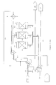
- a storage container 1 contains the water / alcohol mixture to be purified. By storage container, it should also include any unit that can provide a water / alcohol mixture to be treated. In particular, a unit installed in a distillery is considered for purposes of the invention as a storage container.
- a supply line 2 connects the storage container 1 to a vaporization unit 3.
- This vaporization unit 3 is a single evaporator. Said evaporator is supplied with heat by a heat exchanger 11. At the outlet of the evaporator is connected a pipe 4, which is subdivided into branches 4a, 4b, 4c. A superheater 4 'is provided in contact with a portion of the pipe 4. Each branch 4a, 4b, 4c is connected respectively to the inlet balloons 5a, 5b, 5c each comprising a molecular sieve.
- the sieve contained in the flasks is any sieve suitable for the adsorption of water.
- it may have the following characteristics: diameter nominal pores of 3 ⁇ (0.3 nm).
- a suitable sieve is in particular provided by synthetic zeolites of crystalline structure of type A, for example those available from CECA, La Défense, France, under the reference Siliporite EPX 3B.
- a valve system ensures the operation of the balloons alternately, so that among the balloons 5a, 5b, and 5c, at a given moment, two operate for example in dehydration mode and are therefore powered by the steam mixture water / alcohol overheated, while the third operates in regeneration mode.
- Three withdrawal lines 6a, 6b and 6c converging towards a main withdrawal line 6 are respectively output from the balloons 5a, 5b, 5c.
- the main withdrawal pipe 6 is connected to a condensation unit (or heat exchanger or evaporator condenser) 10, at the output of which is connected a collection pipe 16 which is connected to a storage and / or treatment zone 17 of the dehydrated alcohol.
- the installation also comprises a heat transfer fluid circuit.
- coolant is meant a fluid such as water, possibly under pressure, or molten salts, circulating in a circuit distinct from that of the water / alcohol mixture and dehydrated alcohol, which is likely to receive the energy from the dehydrated alcohol during the condensation thereof (this energy exchange generally involving in particular the vaporization of the coolant), and which is likely to give energy to the water / alcohol mixture (This energy exchange generally involving in particular the condensation of said coolant).
- the coolant circuit comprises in particular an evaporation flask 12 supplied with heat by the condensing unit 10.
- the vapor outlet of the evaporation flask 12 feeds a thermo-ejector 13, which is also powered by elsewhere by a source of high pressure steam 14 (produced by a boiler not shown).
- the output of the thermo-ejector 13 is connected to the heat exchanger 11 which heats the vaporization unit 3.
- the heat transfer fluid circuit is completed by a pipe connecting back the heat exchanger 11 to the evaporation flask 12 as well as by a line 15 at the outlet of the evaporation flask 12.
- the line 15 returns to the boiler (not shown) which supplies the source of high-pressure steam 14.
- the installation comprises additional systems of valves, vacuum pumps and possibly overheating to operate the balloons 5a, 5b and 5c desorption.
- Desorption lines may be provided to bring a portion of the dehydrated alcohol back to the flasks 5a, 5b, 5c, possibly with a heating means in contact with these desorption lines.
- effluent withdrawal lines 7a, 7b and 7c are respectively connected to each flask, and they collect in a main withdrawal line of the effluent 7, which after passing through a cooling unit 8 (such a water cooling unit) is connected to a treatment and / or storage zone 9 of the effluent or desorption eluate.
- the number of balloons comprising a molecular sieve may vary and may be one, two or more than three.
- thermo-compression installation is given by the diagram figure 1 bis.
- the vaporization unit 3 is not a simple evaporator (as in the case of the figure 1 ) but on the contrary comprises a distillation unit.
- the first feature of this variant is that the distillation unit comprises at the bottom of the distillation column
- the main withdrawal line of the effluent 7, after passing through the cooling unit 8 opens onto a recycling line 24 which feeds said unit of water. distillation in addition to the feed via the supply line 2.
- the vaporization unit 3 also comprises a distillation column, which is fed in part by the recycle line 24. But this time the coolant circuit is modified and it is partially confused with the main circuit of the mixture water / alcohol, since the distillation column is integrated in the circuit of the coolant. Indeed, the thermo-ejector 13 directly feeds the bottom of the distillation column, while the water withdrawal conduit 25 feeds back the evaporation flask 12. The heat exchanger 11 is missing in this variant of the installation.
- the installation in question comprises a number of elements whose arrangement is similar to that described in connection with the figure 1 , namely: a storage container 1; a supply line 2; a vaporization unit 3 (which in the figure 2 is a simple evaporator), at the output of which is connected a pipe 4, subdivided into branches 4a, 4b, 4c; a superheater 4 'in contact with a portion of the pipe 4; balloons 5a, 5b, 5c each comprising a molecular sieve, fed respectively by the branches 4a, 4b, 4c; at the outlet of the balloons 5a, 5b, 5c, on the one hand from the withdrawal lines 6a, 6b and 6c converging towards a main bleed pipe 6 and on the other hand effluent withdrawal pipes 7a, 7b and 7c gathering in a main withdrawal line of the effluent 7, connected to a cooling unit 8 and then to a treatment and / or storage zone 9 of the desorption eluate or effluent.
- the system in question differs from that of the figure 1 in that the main withdrawal pipe 6 is connected to the inlet of a mechanical compression unit 18. At the outlet thereof, an intermediate pipe 19 feeds a condensing unit 20 at the outlet of which a collection pipe 16 is placed. connected to a storage area and / or treatment 17 of the dehydrated alcohol, as in the previous case.
- the condensing unit 20 directly supplies heat to the vaporization unit 3.
- the other part of the power supply of the vaporization unit 3 comes from an auxiliary circuit comprising a connected heat exchanger 21 at the inlet to a source of low pressure steam 22 and at the outlet to a condensate collecting pipe 23.
- this alternative solution comprises an additional element which is a distillation column 26.
- the main feed of this distillation column is provided by the recycling line 24.
- a line of distillation. water withdrawal 30, while at the top of the column is connected a low pressure vapor withdrawal pipe 27, which A heat exchanger 28 is supplied to the heat exchanger.
- the heat exchanger transfers heat between the pipe 27 and the vaporization unit 3.
- a condensate collecting pipe 29 connected to the outlet of the heat exchanger 28 is divided into two parts, one of which provides a return to the distillation column 26, and the other feeds the vaporization unit 3 (in addition to the supply via the supply line 2).
- it is the heating of the distillation column 26 (and not directly that of the vaporization unit 3) which is provided by the auxiliary circuit consisting of the heat exchanger 21, the steam source 22 and the condensate collection pipe 23.
- the water / alcohol mixture to be treated is taken from the storage container 1 via the feed pipe 2 to the vaporization unit 3.
- the alcohol is ethanol.
- the process according to the invention is in particular intended to be carried out starting from raw materials on sweetened or starchy substrate, within the framework of the chemical industry, and particularly in the context of the production of alcohol. fuel. But other types of alcohol can be dehydrated by the process according to the invention, especially butanol or propanol.
- the water / alcohol mixture is vaporized in the vaporization unit 3.
- the vaporization unit 3 comprises a distillation column
- a first separation between the water and the alcohol takes place (see FIG. figure 1 bis ).
- This separation makes it possible to recover at the bottom of the column desorption water (pure or quasi-pure water) by the water withdrawal line 25.
- a water / alcohol mixture with a higher concentration of alcohol is recovered. Consequently, the vaporized water / alcohol mixture which passes through line 4 has an alcohol concentration which is typically between 80% and 97% vol., The upper limit of this range being reached when a distillation has taken place and the mixture is azeotropic.
- the vaporized mixture is at a pressure of between 1.6 and 2 bar absolute (for example at a pressure of about 1.8 bar absolute) and at a temperature which is approximately the vaporization temperature of the mixture.
- the water / alcohol vapor is superheated in the superheater 4 '.
- the temperature of the mixture is raised at this stage typically from 15 to 45 ° C, so as to exceed the condensation temperature of the water. This temperature is therefore sufficient for the water / alcohol mixture remains in the vapor state during its passage through the balloons equipped with molecular sieve.
- the mixture in the vapor state then arrives at the top of the balloon (s) (denoted 5a to 5c) which operate in dehydration mode, at a temperature of between 105 and 141 ° C. (in particular of approximately 128 ° C.) and at a pressure of between 1.6 and 2 bar absolute (in particular about 1.8 bar absolute); it flows through the molecular sieve in a downward direction.
- the dehydrated alcohol vapor is at a temperature of between 100 and 125 ° C. (in particular about 110 ° -115 ° C.) and at a so-called adsorption pressure of between 1.5 and 1. 9 absolute bar (in particular about 1.7 bar absolute).
- the choice of flow from top to bottom is preferred, since, the sieve loading from the top of the flask, it is thus easier to replace a portion of degraded sieve, the sieve degrading mainly on the first centimeters of flow fluid to be treated.
- the water of the water / alcohol mixture is fixed on the sieve by adsorption.
- dehydrated alcohol leaves the balloons in question by one or more of the withdrawal lines (denoted 6a to 6c) which converge towards the withdrawal line 6.
- each balloon can also operate in turn in regeneration mode.
- regeneration mode a portion of the dehydrated alcohol is reinjected into the balloon from bottom to top. This part of the dehydrated alcohol acts as a desorption fluid.
- the regeneration flask containing a sieve loaded with water has been previously depressurized by means not shown at a so-called desorption pressure pressure, lower than atmospheric pressure and for example between 0.1 and 0.3 bar absolute, especially equal to about 0.25 bar absolute. In this flask, the partial pressure of water then decreases, which causes its desorption of the sieve, and the desorbed water vapor is driven out of the flask through the flow of dehydrated alcohol.
- This water / alcohol effluent which has a high water content (of the order of 20 to 27%), then leaves the flask by one of the effluent withdrawal lines (denoted 7a to 7c) and then by the main effluent withdrawal line 7.
- the effluent (or desorption eluate) is cooled in the cooling unit 8 and then sent to the treatment and / or storage zone 9.
- the vaporization unit 3 comprises a distillation column
- the number of balloons may be one, two, three or more.
- the process is broken down into a succession of cycles, in which a given cycle comprises a first period and a second period: during the first period, a first molecular sieve operates on first in the alcohol dehydration mode (adsorption) while the second molecular sieve operates in regeneration (desorption) mode; then, during the second period, the first molecular sieve operates in desorption mode while the second sieve operates in adsorption mode.
- This alternating operation makes it possible to produce dehydrated alcohol substantially continuously, thereby saving time and optimizing costs relative to the case, which is also possible, where the device comprises only one adsorption tank.
- each molecular sieve undergoes a regeneration in turn, it being understood that the dehydration of the water / alcohol mixture preferably remains ensured at all times by two molecular sieves on all three, with a shift of the desorption front between the two sieves in operation.
- the energy transfer is effected by means of a coolant circuit which, for the purposes of the present description, will be water.
- the withdrawal line 6 brings the dehydrated alcohol vapor into the condensing unit 10, where this dehydrated alcohol vapor condenses (undergoing a temperature drop of the order of 5 to 10 ° C) and transfers energy to the water in the evaporation flask 12, which vaporizes.
- the condensed dehydrated alcohol is fed via a collection line 16 to the storage 17 of the dehydrated alcohol.
- the water vapor produced is sucked by the thermo-ejector 13, from the source of high-pressure steam 14, which constitutes the mechanical source of the thermo-ejector 13.
- the steam produced in the flask 12 has a temperature between 84 and 90 ° C (including about 87 ° C) with the corresponding vapor pressure, namely about 0.62 bar absolute.
- the high-pressure vapor source 14 is supplied at a pressure between 12 and 45 bar absolute, at the corresponding minimum saturation temperature, and may have an overheating temperature of 10 to 40 ° C.
- the thermo-ejector thus supplies compressed steam to the heat exchanger 11.
- the output of the thermo-ejector the compressed vapor is at a pressure between 1 and 1.4 absolute bar (in particular approximately 1.2 bar absolute) corresponding to a saturated vapor temperature of about 105 ° C.
- the thermo-ejector compressed steam at a pressure between about 2.25 and 3 bar absolute corresponding to a saturated steam temperature of 124 to 133 ° C (especially about 128 ° C).
- the compressed vapor condenses in liquid water in the heat exchanger 11, losing about 5 to 10 ° C, and thereby gives up heat to the water / alcohol mixture contained in the vaporization unit 3, allowing its vaporization.
- the coolant condensate (liquid water) at the outlet of the heat exchanger 11 is redirected to the evaporation flask 12 to be partially re-vaporized.
- the final condensate of the coolant, part of the intermediate condensate which is not re-vaporized in the evaporation flask 12 by means of the condensing unit 10, is therefore considerably reduced compared to the systems of the prior art.
- the percentage of re-vaporized condensate is 25 to 35% of the condensate produced by the heat exchanger 11.
- Said final condensate is taken from the outlet line 15 from the evaporation flask 12 , where it can be directed to the boiler supplying the source of high pressure steam 14.
- the coolant circuit is not completely isolated from the alcohol dehydration circuit. Indeed, in this case the heat exchanger 11 is omitted, and the compressed water vapor produced by the thermo-ejector 13 is injected directly into the base of the distillation column of the vaporization unit 3, in which accumulates water separated from the water / alcohol mixture by distillation (phlegmasses). The heat input is therefore directly in the column, without using the intermediary of the heat exchanger 11, which allows an optimization of energy efficiency.
- the water withdrawal pipe 25 at the outlet the lower part of the column ensures a return of water to the evaporation flask 12.
- the energy transfer of the dehydrated alcohol vapor to the vaporization unit 3 can also be carried out according to another embodiment, called mechanical compression (see Figure 2 and Figure 2 bis ).
- the dehydrated alcohol vapor from the withdrawal line 6 passes into a mechanical compression unit 18.
- the pressure of the dehydrated alcohol vapor increases.
- the compression of the alcohol vapors makes it possible to increase the saturation vapor temperature by about 8 ° C., ie to change from a saturated vapor temperature of between 89 and 95 ° C. to a recompressed vapor temperature corresponding to a temperature. saturated vapor between 97 and 103 ° C.
- the compression of the vapors thus makes it possible to pass from a pressure of approximately 1.5 to 2 bar abs, at a pressure of approximately 2.05 to 2.55 bar abs.
- the vapors of dehydrated alcohol before recompression have an overheating of between 10 and 30 ° C.
- the mechanical compressor may be of the "Roots” or “Blower” type with several stages.
- the vapor thus recompressed circulates in the intermediate pipe 19 and can be used to evaporate (and overheat) directly part of the water / alcohol mixture during step (i), without having to use intermediate heat transfer fluid, simply by condensation of the alcohol vapor recompressed in the condensation unit 20.
- the dehydrated alcohol vapors are condensed at a temperature between 95 and 102 ° C at the corresponding equilibrium pressure. As in the case of thermal compression, the condensed dehydrated alcohol leaving the condensing unit 20 is recovered by the collection line 16 and brought to the next storage or treatment unit 17.
- the auxiliary circuit in question can directly supply power to the vaporization unit 3 via a contact between the heat exchanger 21 and the vaporization unit 3, as is the case for example in the embodiment of FIG. figure 2 , or this energy supply can be indirect, as is the case for example in the embodiment of the figure 2 bis.
- the auxiliary circuit heats the distillation column 26 which, being fed desorption eluate by the recycle line 24, ensures a separation of water and alcohol from the desorption eluate.
- the vaporized water / alcohol mixture from the distillation column 26, reconcentrated in alcohol with respect to the desorption eluate, is conveyed via the pipe 27 to the heat exchanger 28, where it condenses and allows the heat to be partially heated. vaporization unit 3.
- the water / alcohol mixture condensate at the outlet of the exchanger 28 is directed by the pipe 29 partly back to the distillation column 26, and partly to the vaporization unit 3.
- the energy recycling allowed by the invention is coupled with a material recycling of the desorption eluate, the alcohol portion of which is recovered.
- the dehydrated alcohol obtained by the process according to the invention in its various embodiments, has a degree of purity typical of 99.9% by volume.
- An example of an installation according to the invention according to the embodiment of the figure 1 bis has been implemented.
- the product to be dehydrated is crude alcohol at 93% vol.
- the plant operates from high pressure steam at 22 effective bar.
- This example reduced the steam consumption to 40 kg per 100 liters of total pure alcohol obtained, compared to 60 kg per 100 liters in the case of a conventional molecular sieve dewatering process from low pressure steam to 2 effective bar.
- the power consumption of the installation is 25 kW.
- FIG. figure 2 bis Another example of use according to the invention according to the embodiment shown in FIG. figure 2 bis has also been implemented.
- This installation uses 35 kg of low pressure steam at 4 effective bar per 100 liters of total alcohol obtained and has a power consumption of 140 kW.
- the average production capacity is about 200 m3 of dehydrated alcohol per day.
Claims (16)
- Verfahren zur Dehydratisierung eines Wasser/Alkohol-Gemischs, das die folgenden Schritte umfasst:(i) Verdampfen und Überhitzen des Wasser/Alkohol-Gemischs auf eine Temperatur, die ausreicht, um das Gemisch im Verlauf von Schritt (ii) im Dampfzustand halten;(ii) Adsorbieren durch Durchleiten des in Schritt (i) erhaltenen Wasser/Alkohol-Gemisch im Dampfzustand durch ein Molekularsieb, um die Adsorption des Wassers auf dem Molekularsieb hervorzurufen, wodurch es möglich ist, dehydratisierten Alkoholdampf zu erhalten;(iii) Kondensieren des in Schritt (ii) erhaltenen dehydratisierten Alkoholdampfs, wodurch es möglich ist, Energie zurückzugewinnen,
wobei das Verdampfen und/oder das Übererhitzen des Wasser/Alkohol-Gemischs aus Schritt (i) mindestens teilweise mithilfe der in Schritt (iii) zurückgewonnenen Energie durchgeführt wird, und wobei:- dem Kondensieren aus Schritt (iii) eine mechanische Verdichtung des dehydratisierten Alkoholdampfs vorausgeht; oder- das Kondensieren aus Schritt (iii) mit dem Verdampfen eines Wärmeträgermediums gekoppelt ist und das verdampfte Wärmeträgermedium komprimiert wird. - Verfahren nach Anspruch 1, wobei es sich bei dem Alkohol um Ethanol handelt.
- Verfahren nach einem der Ansprüche 1 oder 2, wobei das Wasser/Alkohol-Gemisch mindestens 80 Vol.-% Alkohol, bevorzugt mindestens 90 Vol.-% Alkohol, bevorzugt mindestens 92 Vol.-% Alkohol enthält.
- Verfahren nach einem der Ansprüche 1 bis 3, das gleichzeitig und/oder alternativ zu den Schritten (i) bis (iii) den folgenden zusätzlichen Schritt umfasst:(iv) Regenerieren durch Durchleiten eines Teils des dehydratisierten Alkohols bei einem Druck unterhalb des Atmosphärendrucks auf ein mit Wasser gesättigtes Molekularsieb, um das adsorbierte Wasser zu desorbieren,
wobei bei diesem Schritt ein Abfluss erzeugt wird. - Verfahren nach Anspruch 4, das in Schritt (iv) ein Überhitzen des dehydratisierten Alkoholanteils umfasst, bevor er durch das mit Wasser gesättigte Molekularsieb geleitet wird, um das adsorbierte Wasser zu desorbieren.
- Verfahren nach Anspruch 4 oder 5, wobei der in Schritt (iv) erhaltene Abfluss mit dem zu behandelnden Wasser/Alkohol-Gemisch kombiniert wird.
- Verfahren nach einem der Ansprüche 1 bis 6, wobei zwei, drei oder mehr Molekularsiebe in einem alternierenden Modus arbeiten.
- Verfahren nach einem der Ansprüche 1 bis 7, das einen Wasserdampfverdampfverbrauch von weniger als etwa 50 kg je 100 Liter erzeugtem dehydratisiertem Alkohol benötigt.
- Anlage zur Dehydratisierung eines Wasser/Alkohol-Gemischs, umfassend:- eine Zuführleitung (2) für das zu behandelnde Wasser/Alkohol-Gemisch;- eine Verdampfungseinheit (3), um das Verdampfen des Gemischs zu bewirken, das in der vorgenannten Leitung zirkuliert;- einen Überhitzer (4'), um den aus der Verdampfungseinheit (3) stammenden Dampf zu überhitzen;- eine oder mehrere Kolben (5a, 5b, 5c), die mit dem Überhitzer (4') verbunden sind und ein Molekularsieb enthalten;- eine Einheit (10, 20) zum Kondensieren des dehydratisierten Alkohols stromabwärts der Kolben (5a, 5b, 5c), die auch einen Teil der Versorgung der Verdampfungseinheit (3) mit Energie sicherstellt;- eine oder mehrere Leitungen zum Sammeln des dehydratisierten Alkohols (16), die mit dem Auslass der Kondensationseinheit (10, 20) verbunden ist bzw. sind;und ferner umfassend:- eine Einheit zum mechanischen Komprimieren (18) zwischen den Kolben (5a, 5b, 5c) und der Kondensationseinheit (20); oder- einen Wärmeträgermediumkreislauf, wobei der Kreislauf vorgesehen ist, um den Wärmeaustausch zwischen dem Wärmeträgermedium und dem dehydratisierten Alkohol in der Kondensationseinheit (10) einerseits, dem Wasser oder Wasser/Alkohol-Gemisch in der Verdampfungseinheit (3) andererseits mithilfe einer direkten Injektion oder mithilfe eines Wärmetauschers (11) zu ermöglichen, wobei der Wärmeträgermediumkreislauf ein Thermoejektionssystem (13) umfasst, das mit Hochdruckdampf (14) versorgt wird, der dazu bestimmt ist, das Wärmeträgermedium im Dampfzustand rückzuverdichten.
- Anlage nach Anspruch 9, wobei die Verdampfungseinheit (3) eine Destillationssäule umfasst.
- Anlage nach Anspruch 9 oder 10, wobei die Kondensationseinheit (20) vorgesehen ist, um das Wasser/Alkohol-Gemisch in der Verdampfungseinheit (3) direkt zu verdampfen.
- Anlage nach einem der Ansprüche 9 bis 11, die ferner einen Wärmetauscher (21) umfasst, der einen Teil der Energieversorgung der Verdampfungseinheit (3) sicherstellt.
- Anlage nach einem der Ansprüche 9 bis 12, die ferner umfasst:- Desorptionsleitungen, um einen Teil des dehydratisierten Alkohols in die Kolben zurückzuleiten;- Leitungen (7a, 7b, 7c, 7) zur Entnahme des aus den Kolben (5a, 5b, 5c) stammenden Abflusses nach der Regeneration.
- Anlage nach Anspruch 13, die ferner eine Rückführungsleitung (24) umfasst, die dazu bestimmt ist, den Abfluss in die Verdampfungseinheit (3) zurückzuführen.
- Anlage nach Anspruch 13, die ferner eine Rückführungsleitung (24) umfasst, die dazu bestimmt ist, den Abfluss in eine Destillationseinheit (26) zurückzuführen, die einen Wärmetauscher (28) mit Dampf versorgt, der dazu bestimmt ist, Energie an die Verdampfungseinheit (3) zu liefern.
- Anlage nach einem der Ansprüche 13 bis 15, die ferner ein Mittel zum Erhitzen umfasst, das in Kontakt mit den Desorptionsleitungen angeordnet ist.
Applications Claiming Priority (1)
| Application Number | Priority Date | Filing Date | Title |
|---|---|---|---|
| FR0609090A FR2907023B1 (fr) | 2006-10-17 | 2006-10-17 | Nouveau procede de deshydratation d'alcool et installation pour sa mise en oeuvre. |
Publications (2)
| Publication Number | Publication Date |
|---|---|
| EP1920809A1 EP1920809A1 (de) | 2008-05-14 |
| EP1920809B1 true EP1920809B1 (de) | 2014-12-24 |
Family
ID=37946265
Family Applications (1)
| Application Number | Title | Priority Date | Filing Date |
|---|---|---|---|
| EP20070291266 Not-in-force EP1920809B1 (de) | 2006-10-17 | 2007-10-17 | Neuartiges Verfahren zur Dehydratisierung von Alkohol und Anlage für dessen Umsetzung |
Country Status (4)
| Country | Link |
|---|---|
| EP (1) | EP1920809B1 (de) |
| FR (1) | FR2907023B1 (de) |
| RU (1) | RU2400282C2 (de) |
| UA (1) | UA95774C2 (de) |
Families Citing this family (7)
| Publication number | Priority date | Publication date | Assignee | Title |
|---|---|---|---|---|
| FR2933312A1 (fr) * | 2008-07-01 | 2010-01-08 | Pierre Olivier Cogat | Appareillage destine a la deshydratation de composes volatils, du type a compression mecanique des vapeurs, ainsi que des procedes pour sa mise en oeuvre. |
| KR101062918B1 (ko) * | 2008-09-01 | 2011-09-06 | 주식회사 창해에탄올 | 멀티튜브형 에탄올 압력스윙흡착 탈수장치 |
| EP2316549B1 (de) * | 2009-08-03 | 2012-06-27 | Latvijas Lauksaimniecibas Universitäte | Verfahren und Vorrichtung zur Entfernung von Wasser aus Bioethanol durch kombinierte Adsorption und Destillation |
| LV14612B (lv) * | 2011-05-16 | 2013-01-20 | Latvijas Lauksaimniecības Universitātes Aģentūra 'lauksaimniecības Tehnikas Zinātniskais Institūts' | Bioetanola pussausās kongruentās dehidratēšanas iekārtas adsorbenta granulu reģenerācijas bloks |
| CN117658776A (zh) * | 2017-12-28 | 2024-03-08 | 内蒙古伊泰煤基新材料研究院有限公司 | 含水轻醇连续吸附脱水装置和方法 |
| US20210040509A1 (en) * | 2019-08-05 | 2021-02-11 | Bioleap, Inc. | Dehydration energy recycling system and method |
| CN112843766B (zh) * | 2020-12-29 | 2022-06-14 | 复榆(张家港)新材料科技有限公司 | 变压吸附分离溶剂水二元共沸物的吸附分离工艺 |
Family Cites Families (6)
| Publication number | Priority date | Publication date | Assignee | Title |
|---|---|---|---|---|
| DE3037736C2 (de) * | 1980-10-06 | 1984-01-26 | Achim Dipl.-Ing. 6650 Homburg Ballweg | Verfahren zur Entwässerung von Gemischen aus organischen Flüssigkeiten und Wasser |
| BR8103970A (pt) * | 1980-10-20 | 1982-08-24 | Ad Ind Inc | Processo para remocao de vapor de agua de etanol gasoso |
| FR2619107B1 (fr) * | 1987-08-06 | 1989-12-29 | Inst Francais Du Petrole | Procede de deshydratation d'un melange aqueux d'alcools comprenant au moins du methanol et de l'ethanol |
| FR2719039B1 (fr) * | 1994-04-22 | 1996-06-21 | Interis | Nouveau procédé de déshydratation d'alcool par adsorption/regénération sur tamis moléculaire, et installation pour sa mise en Óoeuvre. |
| CA2518809C (en) * | 2003-03-28 | 2009-06-30 | Thermal Kinetics Systems, Llc | Ethanol distillation with distillers soluble solids recovery apparatus |
| FR2855170B1 (fr) * | 2003-05-21 | 2006-07-28 | Ungda | Procede de deshydratation d'ethanol et de flegmes ethanoliques par distillation azeotropique en economie d'energie |
-
2006
- 2006-10-17 FR FR0609090A patent/FR2907023B1/fr active Active
-
2007
- 2007-10-16 UA UAA200711493A patent/UA95774C2/ru unknown
- 2007-10-16 RU RU2007138411A patent/RU2400282C2/ru not_active IP Right Cessation
- 2007-10-17 EP EP20070291266 patent/EP1920809B1/de not_active Not-in-force
Also Published As
| Publication number | Publication date |
|---|---|
| RU2400282C2 (ru) | 2010-09-27 |
| UA95774C2 (ru) | 2011-09-12 |
| FR2907023B1 (fr) | 2011-04-15 |
| EP1920809A1 (de) | 2008-05-14 |
| FR2907023A1 (fr) | 2008-04-18 |
| RU2007138411A (ru) | 2009-04-27 |
Similar Documents
| Publication | Publication Date | Title |
|---|---|---|
| EP1920809B1 (de) | Neuartiges Verfahren zur Dehydratisierung von Alkohol und Anlage für dessen Umsetzung | |
| EP0219521B1 (de) | Verfahren und vorrichtung zum reinigen durch adsorption auf aktivkohle und adsorptionsbehälter dafür | |
| EP1814819B1 (de) | Verfahren und anlage zur kombinierten herstellung von wasserstoff- und kohlenstoffdioxid | |
| EP3465035B1 (de) | Verfahren zur kryogenen trennung eines methan- und luftgashaltigen einsatzstroms, anlage zur herstellung von biomethan durch reinigung von biogasen aus nicht-gefährlichen abfallbehältern (nhwsf) zur durchführung des verfahrens | |
| EP0229803B1 (de) | Verfahren und vorrichtung für luftdestillation | |
| EP2654925B1 (de) | Abschliessendes reinigungsverfahren für biogas | |
| CA2742206A1 (fr) | Production d'hydrogene a partir de gaz reforme et capture simultanee du co2 co-produit | |
| EP3727649A1 (de) | Kryogenes verfahren zur entfernung von stickstoff aus einem entladungsgas | |
| WO2018215716A1 (fr) | Procédé et appareil pour la séparation de l'air par distillation cryogénique | |
| EP2379968A1 (de) | Kohlendioxidgewinnungsverfahren unter verwendung von kryokondensation | |
| WO2004052510A2 (fr) | Procede de recuperation du gaz de haut-fourneau et son utilisation pour la fabrication de la fonte | |
| EP2712419A2 (de) | Verfahren zur trennung von luft durch kryogene destillation | |
| WO2015173499A1 (fr) | Procédé de traitement pour la séparation de dioxyde de carbone et d'hydrogène d'un mélange | |
| EP0914584A1 (de) | Verfahren und einrichtung zur herstellung eines luftgases mit variablen mengen | |
| EP3727648B1 (de) | Verfahren zum destillieren eines sauerstoffhaltigen gasstroms | |
| FR2849172A1 (fr) | Procede de distillation d'air ameliore, et installation de mise en oeuvre de ce procede | |
| FR2719039A1 (fr) | Nouveau procédé de déshydratation d'alcool par adsorption/regénération sur tamis moléculaire, et installation pour sa mise en Óoeuvre. | |
| EP1844282A1 (de) | Verfahren und system zur erzeugung von kohlenmonoxid durch kryogene destillation | |
| FR2855170A1 (fr) | Procede de deshydratation d'ethanol et de flegmes ethanoliques par distillation azeotropique en economie d'energie | |
| FR2919717A1 (fr) | Procede et appareil de separation d'air avec compression de produit | |
| FR2743069A1 (fr) | Procede de regeneration d'un compose liquide de la famille des glycols, utilise dans la deshydratation d'un gaz | |
| WO2022106768A1 (fr) | Procede de separation cryogenique d'un debit d'alimentation a base de biomethane, procede de production de biomethane integrant ladite separation cryogenique et installation associee | |
| WO2008089527A1 (en) | Pressure swing adsorption process and apparatus, including thermal energy recovery | |
| WO2010007281A2 (fr) | Procede de production de gaz de synthese par reformage a la vapeur d'hydrocarbures utilisant de l'air enrichi en oxygene en tant que comburant |
Legal Events
| Date | Code | Title | Description |
|---|---|---|---|
| PUAI | Public reference made under article 153(3) epc to a published international application that has entered the european phase |
Free format text: ORIGINAL CODE: 0009012 |
|
| AK | Designated contracting states |
Kind code of ref document: A1 Designated state(s): AT BE BG CH CY CZ DE DK EE ES FI FR GB GR HU IE IS IT LI LT LU LV MC MT NL PL PT RO SE SI SK TR |
|
| AX | Request for extension of the european patent |
Extension state: AL BA HR MK RS |
|
| 17P | Request for examination filed |
Effective date: 20081114 |
|
| 17Q | First examination report despatched |
Effective date: 20081215 |
|
| AKX | Designation fees paid |
Designated state(s): AT BE BG CH CY CZ DE DK EE ES FI FR GB GR HU IE IS IT LI LT LU LV MC MT NL PL PT RO SE SI SK TR |
|
| REG | Reference to a national code |
Ref country code: DE Ref legal event code: R079 Ref document number: 602007039782 Country of ref document: DE Free format text: PREVIOUS MAIN CLASS: B01D0005000000 Ipc: B01D0001280000 |
|
| GRAJ | Information related to disapproval of communication of intention to grant by the applicant or resumption of examination proceedings by the epo deleted |
Free format text: ORIGINAL CODE: EPIDOSDIGR1 |
|
| GRAP | Despatch of communication of intention to grant a patent |
Free format text: ORIGINAL CODE: EPIDOSNIGR1 |
|
| RIC1 | Information provided on ipc code assigned before grant |
Ipc: B01D 3/00 20060101ALI20140702BHEP Ipc: B01D 53/26 20060101ALI20140702BHEP Ipc: B01D 1/28 20060101AFI20140702BHEP Ipc: C07C 29/76 20060101ALI20140702BHEP |
|
| INTG | Intention to grant announced |
Effective date: 20140725 |
|
| GRAS | Grant fee paid |
Free format text: ORIGINAL CODE: EPIDOSNIGR3 |
|
| GRAA | (expected) grant |
Free format text: ORIGINAL CODE: 0009210 |
|
| AK | Designated contracting states |
Kind code of ref document: B1 Designated state(s): AT BE BG CH CY CZ DE DK EE ES FI FR GB GR HU IE IS IT LI LT LU LV MC MT NL PL PT RO SE SI SK TR |
|
| REG | Reference to a national code |
Ref country code: GB Ref legal event code: FG4D Free format text: NOT ENGLISH |
|
| REG | Reference to a national code |
Ref country code: CH Ref legal event code: EP |
|
| REG | Reference to a national code |
Ref country code: IE Ref legal event code: FG4D Free format text: LANGUAGE OF EP DOCUMENT: FRENCH |
|
| REG | Reference to a national code |
Ref country code: AT Ref legal event code: REF Ref document number: 702838 Country of ref document: AT Kind code of ref document: T Effective date: 20150115 |
|
| REG | Reference to a national code |
Ref country code: DE Ref legal event code: R096 Ref document number: 602007039782 Country of ref document: DE Effective date: 20150212 |
|
| REG | Reference to a national code |
Ref country code: NL Ref legal event code: VDEP Effective date: 20141224 |
|
| PG25 | Lapsed in a contracting state [announced via postgrant information from national office to epo] |
Ref country code: FI Free format text: LAPSE BECAUSE OF FAILURE TO SUBMIT A TRANSLATION OF THE DESCRIPTION OR TO PAY THE FEE WITHIN THE PRESCRIBED TIME-LIMIT Effective date: 20141224 Ref country code: LT Free format text: LAPSE BECAUSE OF FAILURE TO SUBMIT A TRANSLATION OF THE DESCRIPTION OR TO PAY THE FEE WITHIN THE PRESCRIBED TIME-LIMIT Effective date: 20141224 |
|
| REG | Reference to a national code |
Ref country code: LT Ref legal event code: MG4D |
|
| PG25 | Lapsed in a contracting state [announced via postgrant information from national office to epo] |
Ref country code: GR Free format text: LAPSE BECAUSE OF FAILURE TO SUBMIT A TRANSLATION OF THE DESCRIPTION OR TO PAY THE FEE WITHIN THE PRESCRIBED TIME-LIMIT Effective date: 20150325 Ref country code: SE Free format text: LAPSE BECAUSE OF FAILURE TO SUBMIT A TRANSLATION OF THE DESCRIPTION OR TO PAY THE FEE WITHIN THE PRESCRIBED TIME-LIMIT Effective date: 20141224 Ref country code: LV Free format text: LAPSE BECAUSE OF FAILURE TO SUBMIT A TRANSLATION OF THE DESCRIPTION OR TO PAY THE FEE WITHIN THE PRESCRIBED TIME-LIMIT Effective date: 20141224 |
|
| REG | Reference to a national code |
Ref country code: AT Ref legal event code: MK05 Ref document number: 702838 Country of ref document: AT Kind code of ref document: T Effective date: 20141224 |
|
| PG25 | Lapsed in a contracting state [announced via postgrant information from national office to epo] |
Ref country code: NL Free format text: LAPSE BECAUSE OF FAILURE TO SUBMIT A TRANSLATION OF THE DESCRIPTION OR TO PAY THE FEE WITHIN THE PRESCRIBED TIME-LIMIT Effective date: 20141224 |
|
| PG25 | Lapsed in a contracting state [announced via postgrant information from national office to epo] |
Ref country code: ES Free format text: LAPSE BECAUSE OF FAILURE TO SUBMIT A TRANSLATION OF THE DESCRIPTION OR TO PAY THE FEE WITHIN THE PRESCRIBED TIME-LIMIT Effective date: 20141224 Ref country code: CZ Free format text: LAPSE BECAUSE OF FAILURE TO SUBMIT A TRANSLATION OF THE DESCRIPTION OR TO PAY THE FEE WITHIN THE PRESCRIBED TIME-LIMIT Effective date: 20141224 Ref country code: SK Free format text: LAPSE BECAUSE OF FAILURE TO SUBMIT A TRANSLATION OF THE DESCRIPTION OR TO PAY THE FEE WITHIN THE PRESCRIBED TIME-LIMIT Effective date: 20141224 Ref country code: RO Free format text: LAPSE BECAUSE OF FAILURE TO SUBMIT A TRANSLATION OF THE DESCRIPTION OR TO PAY THE FEE WITHIN THE PRESCRIBED TIME-LIMIT Effective date: 20141224 Ref country code: EE Free format text: LAPSE BECAUSE OF FAILURE TO SUBMIT A TRANSLATION OF THE DESCRIPTION OR TO PAY THE FEE WITHIN THE PRESCRIBED TIME-LIMIT Effective date: 20141224 |
|
| PG25 | Lapsed in a contracting state [announced via postgrant information from national office to epo] |
Ref country code: IS Free format text: LAPSE BECAUSE OF FAILURE TO SUBMIT A TRANSLATION OF THE DESCRIPTION OR TO PAY THE FEE WITHIN THE PRESCRIBED TIME-LIMIT Effective date: 20150424 Ref country code: PL Free format text: LAPSE BECAUSE OF FAILURE TO SUBMIT A TRANSLATION OF THE DESCRIPTION OR TO PAY THE FEE WITHIN THE PRESCRIBED TIME-LIMIT Effective date: 20141224 Ref country code: AT Free format text: LAPSE BECAUSE OF FAILURE TO SUBMIT A TRANSLATION OF THE DESCRIPTION OR TO PAY THE FEE WITHIN THE PRESCRIBED TIME-LIMIT Effective date: 20141224 |
|
| REG | Reference to a national code |
Ref country code: DE Ref legal event code: R097 Ref document number: 602007039782 Country of ref document: DE |
|
| PG25 | Lapsed in a contracting state [announced via postgrant information from national office to epo] |
Ref country code: DK Free format text: LAPSE BECAUSE OF FAILURE TO SUBMIT A TRANSLATION OF THE DESCRIPTION OR TO PAY THE FEE WITHIN THE PRESCRIBED TIME-LIMIT Effective date: 20141224 |
|
| REG | Reference to a national code |
Ref country code: FR Ref legal event code: PLFP Year of fee payment: 9 |
|
| PLBE | No opposition filed within time limit |
Free format text: ORIGINAL CODE: 0009261 |
|
| STAA | Information on the status of an ep patent application or granted ep patent |
Free format text: STATUS: NO OPPOSITION FILED WITHIN TIME LIMIT |
|
| 26N | No opposition filed |
Effective date: 20150925 |
|
| PG25 | Lapsed in a contracting state [announced via postgrant information from national office to epo] |
Ref country code: IT Free format text: LAPSE BECAUSE OF FAILURE TO SUBMIT A TRANSLATION OF THE DESCRIPTION OR TO PAY THE FEE WITHIN THE PRESCRIBED TIME-LIMIT Effective date: 20141224 |
|
| PG25 | Lapsed in a contracting state [announced via postgrant information from national office to epo] |
Ref country code: SI Free format text: LAPSE BECAUSE OF FAILURE TO SUBMIT A TRANSLATION OF THE DESCRIPTION OR TO PAY THE FEE WITHIN THE PRESCRIBED TIME-LIMIT Effective date: 20141224 |
|
| REG | Reference to a national code |
Ref country code: DE Ref legal event code: R119 Ref document number: 602007039782 Country of ref document: DE |
|
| PG25 | Lapsed in a contracting state [announced via postgrant information from national office to epo] |
Ref country code: LU Free format text: LAPSE BECAUSE OF FAILURE TO SUBMIT A TRANSLATION OF THE DESCRIPTION OR TO PAY THE FEE WITHIN THE PRESCRIBED TIME-LIMIT Effective date: 20151017 |
|
| REG | Reference to a national code |
Ref country code: CH Ref legal event code: PL |
|
| GBPC | Gb: european patent ceased through non-payment of renewal fee |
Effective date: 20151017 |
|
| PG25 | Lapsed in a contracting state [announced via postgrant information from national office to epo] |
Ref country code: MC Free format text: LAPSE BECAUSE OF FAILURE TO SUBMIT A TRANSLATION OF THE DESCRIPTION OR TO PAY THE FEE WITHIN THE PRESCRIBED TIME-LIMIT Effective date: 20141224 |
|
| REG | Reference to a national code |
Ref country code: IE Ref legal event code: MM4A |
|
| PG25 | Lapsed in a contracting state [announced via postgrant information from national office to epo] |
Ref country code: DE Free format text: LAPSE BECAUSE OF NON-PAYMENT OF DUE FEES Effective date: 20160503 Ref country code: GB Free format text: LAPSE BECAUSE OF NON-PAYMENT OF DUE FEES Effective date: 20151017 Ref country code: CH Free format text: LAPSE BECAUSE OF NON-PAYMENT OF DUE FEES Effective date: 20151031 Ref country code: LI Free format text: LAPSE BECAUSE OF NON-PAYMENT OF DUE FEES Effective date: 20151031 |
|
| REG | Reference to a national code |
Ref country code: FR Ref legal event code: PLFP Year of fee payment: 10 |
|
| PG25 | Lapsed in a contracting state [announced via postgrant information from national office to epo] |
Ref country code: IE Free format text: LAPSE BECAUSE OF NON-PAYMENT OF DUE FEES Effective date: 20151017 |
|
| PG25 | Lapsed in a contracting state [announced via postgrant information from national office to epo] |
Ref country code: HU Free format text: LAPSE BECAUSE OF FAILURE TO SUBMIT A TRANSLATION OF THE DESCRIPTION OR TO PAY THE FEE WITHIN THE PRESCRIBED TIME-LIMIT; INVALID AB INITIO Effective date: 20071017 Ref country code: BG Free format text: LAPSE BECAUSE OF FAILURE TO SUBMIT A TRANSLATION OF THE DESCRIPTION OR TO PAY THE FEE WITHIN THE PRESCRIBED TIME-LIMIT Effective date: 20141224 |
|
| PG25 | Lapsed in a contracting state [announced via postgrant information from national office to epo] |
Ref country code: CY Free format text: LAPSE BECAUSE OF FAILURE TO SUBMIT A TRANSLATION OF THE DESCRIPTION OR TO PAY THE FEE WITHIN THE PRESCRIBED TIME-LIMIT Effective date: 20141224 |
|
| PG25 | Lapsed in a contracting state [announced via postgrant information from national office to epo] |
Ref country code: BE Free format text: LAPSE BECAUSE OF NON-PAYMENT OF DUE FEES Effective date: 20151031 |
|
| PG25 | Lapsed in a contracting state [announced via postgrant information from national office to epo] |
Ref country code: MT Free format text: LAPSE BECAUSE OF FAILURE TO SUBMIT A TRANSLATION OF THE DESCRIPTION OR TO PAY THE FEE WITHIN THE PRESCRIBED TIME-LIMIT Effective date: 20141224 Ref country code: TR Free format text: LAPSE BECAUSE OF FAILURE TO SUBMIT A TRANSLATION OF THE DESCRIPTION OR TO PAY THE FEE WITHIN THE PRESCRIBED TIME-LIMIT Effective date: 20141224 |
|
| REG | Reference to a national code |
Ref country code: FR Ref legal event code: PLFP Year of fee payment: 11 |
|
| PGFP | Annual fee paid to national office [announced via postgrant information from national office to epo] |
Ref country code: FR Payment date: 20170831 Year of fee payment: 11 |
|
| PG25 | Lapsed in a contracting state [announced via postgrant information from national office to epo] |
Ref country code: PT Free format text: LAPSE BECAUSE OF FAILURE TO SUBMIT A TRANSLATION OF THE DESCRIPTION OR TO PAY THE FEE WITHIN THE PRESCRIBED TIME-LIMIT Effective date: 20141224 |
|
| PG25 | Lapsed in a contracting state [announced via postgrant information from national office to epo] |
Ref country code: FR Free format text: LAPSE BECAUSE OF NON-PAYMENT OF DUE FEES Effective date: 20181031 |