EP1920743B2 - Luftgeformtes Fasernetz - Google Patents
Luftgeformtes Fasernetz Download PDFInfo
- Publication number
- EP1920743B2 EP1920743B2 EP08001169.5A EP08001169A EP1920743B2 EP 1920743 B2 EP1920743 B2 EP 1920743B2 EP 08001169 A EP08001169 A EP 08001169A EP 1920743 B2 EP1920743 B2 EP 1920743B2
- Authority
- EP
- European Patent Office
- Prior art keywords
- forming
- liquid holding
- forming surface
- holding formation
- drum
- Prior art date
- Legal status (The legal status is an assumption and is not a legal conclusion. Google has not performed a legal analysis and makes no representation as to the accuracy of the status listed.)
- Expired - Lifetime
Links
Images


Classifications
-
- A—HUMAN NECESSITIES
- A61—MEDICAL OR VETERINARY SCIENCE; HYGIENE
- A61F—FILTERS IMPLANTABLE INTO BLOOD VESSELS; PROSTHESES; DEVICES PROVIDING PATENCY TO, OR PREVENTING COLLAPSING OF, TUBULAR STRUCTURES OF THE BODY, e.g. STENTS; ORTHOPAEDIC, NURSING OR CONTRACEPTIVE DEVICES; FOMENTATION; TREATMENT OR PROTECTION OF EYES OR EARS; BANDAGES, DRESSINGS OR ABSORBENT PADS; FIRST-AID KITS
- A61F13/00—Bandages or dressings; Absorbent pads
- A61F13/15—Absorbent pads, e.g. sanitary towels, swabs or tampons for external or internal application to the body; Supporting or fastening means therefor; Tampon applicators
- A61F13/53—Absorbent pads, e.g. sanitary towels, swabs or tampons for external or internal application to the body; Supporting or fastening means therefor; Tampon applicators characterised by the absorbing medium
- A61F13/531—Absorbent pads, e.g. sanitary towels, swabs or tampons for external or internal application to the body; Supporting or fastening means therefor; Tampon applicators characterised by the absorbing medium having a homogeneous composition through the thickness of the pad
- A61F13/532—Absorbent pads, e.g. sanitary towels, swabs or tampons for external or internal application to the body; Supporting or fastening means therefor; Tampon applicators characterised by the absorbing medium having a homogeneous composition through the thickness of the pad inhomogeneous in the plane of the pad
-
- A—HUMAN NECESSITIES
- A61—MEDICAL OR VETERINARY SCIENCE; HYGIENE
- A61F—FILTERS IMPLANTABLE INTO BLOOD VESSELS; PROSTHESES; DEVICES PROVIDING PATENCY TO, OR PREVENTING COLLAPSING OF, TUBULAR STRUCTURES OF THE BODY, e.g. STENTS; ORTHOPAEDIC, NURSING OR CONTRACEPTIVE DEVICES; FOMENTATION; TREATMENT OR PROTECTION OF EYES OR EARS; BANDAGES, DRESSINGS OR ABSORBENT PADS; FIRST-AID KITS
- A61F13/00—Bandages or dressings; Absorbent pads
- A61F13/15—Absorbent pads, e.g. sanitary towels, swabs or tampons for external or internal application to the body; Supporting or fastening means therefor; Tampon applicators
- A61F13/15577—Apparatus or processes for manufacturing
- A61F13/15617—Making absorbent pads from fibres or pulverulent material with or without treatment of the fibres
- A61F13/15626—Making fibrous pads without outer layers
-
- Y—GENERAL TAGGING OF NEW TECHNOLOGICAL DEVELOPMENTS; GENERAL TAGGING OF CROSS-SECTIONAL TECHNOLOGIES SPANNING OVER SEVERAL SECTIONS OF THE IPC; TECHNICAL SUBJECTS COVERED BY FORMER USPC CROSS-REFERENCE ART COLLECTIONS [XRACs] AND DIGESTS
- Y10—TECHNICAL SUBJECTS COVERED BY FORMER USPC
- Y10T—TECHNICAL SUBJECTS COVERED BY FORMER US CLASSIFICATION
- Y10T442/00—Fabric [woven, knitted, or nonwoven textile or cloth, etc.]
- Y10T442/60—Nonwoven fabric [i.e., nonwoven strand or fiber material]
Definitions
- This invention relates generally to a method of forming an absorbent core.
- the absorbent core can be used for applications such as disposable diapers, child's training pants, feminine care articles, incontinence articles, and the like.
- An absorbent core is known from EP 0700673 A1 . Further prior art absorbent cores are disclosed in US 4059114 , WO 02/34188 , US 5451442 and EP 1210925 .
- fibrous web materials such as air formed fibrous webs
- a fibrous sheet of cellulosic or other suitable absorbent material which has been fiberized in a conventional fiberizer, or other shredding or comminuting device, to form discrete fibers.
- particles of superabsorbent material have been mixed with the fibers.
- the fibers and superabsorbent particles have then been entrained in an air stream and directed to a foraminous forming surface upon which the fibers and superabsorbent particles have been deposited to form an absorbent fibrous web.
- An absorbent core formed in this fashion has a liquid holding formation which is intended to be the primary repository for liquid to be held by the absorbent core.
- the liquid holding formation has conventionally been formed to have a greater amount of fibrous and superabsorbent material (SAM) than surrounding regions and is generally thicker than the surrounding regions of fibrous material.
- SAM fibrous and superabsorbent material
- the forming surfaces used in such systems have been constructed with a perforated plate or wire screen grid and can typically employ a pneumatic flow mechanism, such as vacuum suction apparatus, to produce a pressure differential across the forming surface.
- the pressure difference causes an airflow through the openings or perforations in the plate or screen of the forming surface.
- the use of vacuum suction to draw the air-entrained fiber stream onto the forming surface, and pass the airflow through the forming surface is presently employed in highspeed commercial operations.
- fibrous material is deposited on the forming surface as it passes through a chamber of the fluent fibers, forming a layer of fibrous material on the forming surface.
- the liquid holding formation is typically formed through the provision of a pocket in the forming surface. It has been found that instead of depositing fibrous material to a greater depth in the pocket the depth of material often is nearly the same as in the shallower surrounding regions.
- the absorbent core is cut or scarfed after forming on the forming surface so that the surrounding areas end up with a lesser thickness than the region of the liquid holding formation.
- there is often a marked dip in the scarfed surface of the finished absorbent core in the liquid holding formation area indicating that less than a full desired thickness of fibrous material has been deposited.
- the reduction in the amount of fibrous material (and superabsorbent material) corresponds to a reduction in the quantity of liquid which can be held by the liquid holding formation and the absorbent core. Attempts to remedy this and other problems associated with air flow by control of the vacuum pressure on the forming surface have been complicated and difficult to control.
- the present invention provides a method of forming an absorbent core in accordance with claim 1.
- the apparatus has a machine-direction MD which extends generally in the direction of motion of the machine, a lateral cross-direction CD which extends transversely to the machine direction, and a z-direction Z.
- the machine-direction MD is the direction along which a particular component or material is transported lengthwise along and through a particular, local position of the apparatus.
- the cross-direction CD lies generally within the plane of the material being transported through the process, and is transverse to the local machine-direction MD.
- the z-direction Z is aligned substantially perpendicular to both the machine-direction MD and the cross-direction CD, and extends generally along a depth-wise, thickness dimension of the material.
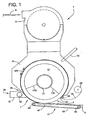
- Apparatus 1 for forming a fibrous web 3 can include a movable, foraminous forming surface 5 extending around the circumference of a drum 7 (the reference numerals designating their subjects generally).
- the drum 7 is mounted on a shaft 9 connected by bearings 11 to a support 13.
- the drum includes a circular wall 15 connected to the shaft 9 for conjoint rotation therewith.
- the shaft 9 is driven in rotation by a suitable motor or line shaft (not shown) in a counterclockwise direction as seen in Fig. 1 .
- the wall 15 cantilevers the forming surface 5 and the opposite side of the drum 7 is open.
- a vacuum duct 17 located radially inwardly of the forming surface extends over an arc of the drum interior.
- the vacuum duct 17 has an arcuate, elongate entrance opening 19 under the foraminous forming surface 5, as will be described in more detail hereinafter, for fluid communication between the vacuum duct and the forming surface.
- the vacuum duct 17 is mounted on and in fluid communication with a vacuum conduit 21 connected to a vacuum source 23 (represented diagrammatically in Fig. 2 ).
- the vacuum source 23 may be, for example, an exhaust fan.
- the vacuum duct 17 is connected to the vacuum supply conduit 21 along an outer peripheral surface of the conduit, and extends circumferentially of the conduit.
- the vacuum duct 17 projects radially outwardly from the vacuum conduit 21 toward the forming surface 5 and includes axially spaced side walls 17A and angularly spaced end walls 17B.
- the shaft 9 extends through the wall 15 and into the vacuum supply conduit 21 where it is received in a bearing 10 connected to a brace 12 within the conduit.
- the bearing 10 is sealed with the vacuum supply conduit 21 so that air is not drawn in around the shaft 9 where it enters the conduit.
- the brace 12 and entire conduit 21 are supported by an overhead mount 14.
- a drum rim 18 is mounted on the wall 15 of the drum 7 and has a multiplicity of holes over its surface area to provide a substantially free movement of air through the thickness of the rim.
- the rim 18 is generally tubular in shape and extends around the axis of rotation of the shaft 9 near the periphery of the wall 15.
- the rim 18 is cantilevered away from the drum wall 15, and has a radially inward-facing surface positioned closely adjacent to the entrance opening 19 of the vacuum duct 17.
- rim seals 20 are mounted on the inward-facing surface of the rim 18 for sliding sealing engagement with the walls 17A of the vacuum duct. Seals (not shown) are also mounted on the end walls 17B of the vacuum duct 17 for sliding sealing engagement with the inward-facing surface of the rim 18.
- the seals may be formed of a suitable material such as felt to permit the sliding sealing engagements.
- the apparatus 1 further includes a forming chamber 25 through which the forming surface 5 is movable.
- the forming chamber 25 has an entrance 27 where the forming surface 5 enters the chamber substantially free of fibrous material, and an exit 29 where the forming surface leaves the chamber substantially filled with fibrous material.
- a fiberizer 31 provides fibrous material into the forming chamber 25, and the vacuum source 23 ( Fig. 2 ) creates a vacuum pressure in the vacuum duct 17 relative to the interior of the chamber 25.
- the forming surface 5 enters and then traverses through the forming chamber 25, the component materials of the fibrous web 3 are operatively carried or transported by an entraining air stream that is drawn through the forming surface 5.
- the pressure differential across the forming surface 5 causes the fluent fibers in the chamber 25 to be drawn to the forming surface.
- the selected fibrous material may be suitably derived from a batt B of cellulosic fibers (e.g., wood pulp fibers) or other source of natural and/or synthetic fibers, which has been disintegrated, in a manner well known in the art, to provide an operative quantity of individual, loose fibers.
- the fiberizer 31 receives a selected web-forming material, converts the web-forming material into individual fibers, and delivers the fibers into the forming chamber 25.
- the fiberizer 31 can be a rotary hammer mill or a rotatable picker roll.
- fibers may be provided in other ways by other devices within the scope of the present invention. Suitable fiberizers are available from Paper Converting Machine Company, a business having offices located in Green Bay, Wisconsin, U.S.A.
- Other component materials for producing the fibrous web 3 may also be delivered into the forming chamber 25.
- particles or fibers of superabsorbent material may be introduced into the forming chamber 25 by employing conventional mechanisms, such as pipes, channels, spreaders, nozzles and the like, as well as combinations thereof.
- the superabsorbent material is delivered into the forming chamber 25 by employing a schematically represented delivery conduit and nozzle system 33.
- the fibers, particles and other desired web material may be entrained in any suitable gaseous medium. Accordingly, any references herein to air as being the entraining medium should be understood to be a general reference which encompasses any other operative entraining gas.
- Superabsorbent materials are well known in the art, and are readily available from various suppliers. For example, FAVOR
- SMX 880 superabsorbent is available from Stockhausen, Inc., a business having offices located in Greensboro, North Carolina, U.S.A.; and Drytech 2035 is available from Dow Chemical Company, a business having offices located in Midland, Michigan, U.S.A.
- the stream of fluent fibers and particles pass through the forming chamber 25 for deposition onto the forming surface 5.
- the forming chamber 25 can serve to direct and concentrate the air-entrained fibers and particles, and to provide a desired velocity profile in the air-entrained stream of fibers and particles.
- the forming chamber 25 is supported by suitable structural members, which together form a support frame for the forming chamber.
- the frame may be anchored and/or joined to other suitable structural components, as necessary or desirable.
- the construction and operation of such forming chambers 25 is well known and will not be described in further detail herein. Instead of applying the fibers (and SAM) directly to the forming surface, it is known to place a porous substrate over the forming surface on which the fibers are deposited.
- Suitable substrates may, for example, be formed from tissue, spunbond, nonwoven or woven materials.
- a web 26 of substrate is shown in phantom in Fig. 1 to extend from a roll 28 into the entrance 27 of the forming chamber 25.
- the roll 28 can be held and the web 26 fed out by suitable delivery device (not shown in its entirety) as is known in the art.
- a roller 30 of the delivery device is shown for guiding the web 26 into the entrance 27.
- the web 26, when used, overlies the forming surface 5 so that fibers and superabsorbent material are deposited on the web rather than directly on the forming surface 5.
- the vacuum causes the web 26 to conform to the shape of the forming surface 5.
- the forming surface 5 is illustrated as being part of the forming drum 7, but it is to be understood that other techniques for providing the forming surface 5 may also be employed.
- the forming surface 5 may be provided by an endless forming belt (not shown).
- a forming belt of this type is shown in U.S. Patent No. 5,466,409 , entitled FORMING BELT FOR THREE-DIMENSIONAL FORMING APPLICATIONS by M. Partridge et al. which issued on November 14, 1995.
- the foraminous forming surface 5 is defined in the illustrated embodiment by a series of form members 34 which are arranged end-to-end around the periphery of the forming drum 7 and independently attached to the drum.
- the form members 34 each define a substantially identical pattern 36 in which fibrous material is deposited.
- the patterns 36 correspond to a desired shape of individual absorbent cores 38 ( one of which is shown in Fig. 6 ) which repeats over the circumference of the drum.
- partially repeating or non-repeating pattern shapes may be used with the present invention.
- a conveying air stream is drawn through the foraminous forming surface 5 into the vacuum duct 17 on the interior of the forming drum 7, and is subsequently passed out of the drum through the vacuum supply conduit 21.
- the air component is passed through the forming surface and the fibers-particles component is retained by the forming surface to form a nonwoven fibrous web 3 thereon. Subsequently, with the rotation of the drum 7, the formed web 3 is removed from the forming surface 5.
- the drum 7 carrying the air formed fibrous web 3 deposited on the forming surface 5 in the forming chamber 25 passes out of the chamber through the exit 29 to a scarfing system, generally indicated at 35 in Fig. 1 , where excess thickness of the fibrous web can be trimmed and removed to a predetermined extent.
- the scarfing system includes a scarfing chamber 37 and a scarfing roll 39 which is positioned within the scarfing chamber.
- the scarfing roll 39 abrades excess fibrous material from the fibrous web 3, and the removed fibers are transported away from the scarfing chamber 37 with a suitable discharge conduit (not shown), as well known in the art.
- the removed fibrous material may, for example, be recycled back into the forming chamber 25 or the fiberizer 31, as desired.
- the scarfing roll 39 can rearrange and redistribute the web material along the longitudinal machine-direction MD of the web 3 and/or along the lateral cross-direction CD of the web.
- the profile of the web made by a scarfing roll may be flat (as with scarfing roll 39), but also may be shaped or irregular as desired by selection and arrangement of teeth (not shown) on the scarfing roll.
- the rotatable scarfing roll 39 is operatively connected and joined to a suitable shaft member, and is driven by a suitable drive system (not shown).
- the drive system may include any conventional apparatus, such as provided by a dedicated motor, or a coupling, gear or other transmission mechanism operatively connected to the motor or other drive mechanism employed to rotate the forming drum 7.
- the scarfing roll system 35 can provide a conventional trimming mechanism for removing or redistributing any excess, z-directional thickness of the air formed fibrous web that has been deposited on the forming surface 5.
- the scarfing operation can yield a fibrous web having a selected contour on a major face-surface of the fibrous web that has been contacted by the scarfing roll 39.
- the surface of the scarfing roll can be adjusted to provide a desired contour along the scarfed surface of the fibrous web 3.
- the scarfing roll 39 can, for example, be configured to provide a substantially flat surface along the scarfed surface of the fibrous web 3.
- the scarfing roll 39 can optionally be configured to provide a non-flat surface.
- the scarfing roll 39 is disposed in spaced adjacent relationship to the forming surface 5, and the forming surface is translated past the scarfing roll by rotation of the drum 7.
- the scarfing roll 39 rotates in a direction which moves a contacting surface of the scarfing roll in a counter-direction that is opposite the rotation of the drum 7 and the movement direction of the air formed fibrous web 3.
- the scarfing roll 39 may be rotated so that the roll surface moves in the same direction as the forming surface 5 on the forming drum 7.
- the rotational speed of the scarfing roll 39 should be suitably selected to provide an effective scarfing action against the contacted surface of the formed fibrous web 3.
- any other suitable trimming mechanism may be employed in place of the scarfing roll 39 assembly to provide a cutting or abrading action to the air formed fibrous web by a relative movement between the fibrous web 3 and the selected trimming mechanism.
- the portion of the forming surface 5 that is carrying the air formed fibrous web 3 can be moved to a release zone of the apparatus 1.
- vacuum causes the web 3 to transfer from the forming surface 5 onto a conveyor indicated generally at 41.
- the release can be assisted by the application of air pressure from the interior of the drum 7.
- the conveyor 41 receives the formed fibrous web 3 from the forming drum 7, and conveys the web to a collection area or to a location for further processing (not shown).
- Suitable conveyors can, for example, include conveyer belts, vacuum drums, transport rollers, electromagnetic suspension conveyors, fluid suspension conveyors or the like, as well as combinations thereof.
- the conveyor 41 includes an endless conveyor belt 43 disposed about rollers 45.
- a vacuum suction box 47 is located below the conveyor belt 43 to remove the web 3 from the forming surface 5.
- the belt 43 is perforate and the vacuum box 47 defines a plenum beneath the portion of the belt in close proximity to the forming surface so that a vacuum is communicated to the fibrous web 3 on the drum 7.
- Removal of the web 3 can alternatively be accomplished by the weight of the web, by centrifugal force, by mechanical ejection, by positive air pressure or by some combination or by another suitable method.
- the positive air pressure can be produced, for example, by a source of compressed air (not shown) such as a fan which generates a pressurized air flow that exerts a force directed outwardly through the forming surface 5.
- the removed fibrous web includes an interconnected series of absorbent cores, and each body has an selected surface contour which substantially matches the contour provided by the corresponding portions of the forming surface 5 upon which each individual pad was formed. It is also possible to contour the scarfed side of the web 3.
- Suitable forming drum systems for producing air formed fibrous webs are well known in the art.
- U.S. Patent No. 4,666,647 entitled APPARATUS AND METHOD FOR FORMING A LAID FIBROUS WEB by K. Enloe et al. which issued May 19, 1987
- U.S. Patent No. 4,761,258 entitled CONTROLLED FORMATION OF LIGHT AND HEAVY FLUFF ZONES by K. Enloe which issued August 2, 1988.
- Other forming drum systems are described in U.S. Patent No. 6,330,735 , entitled APPARATUS AND PROCESS FOR FORMING A LAID FIBROUS WEB WITH ENHANCED BASIS WEIGHT CAPABILITY by J. T.
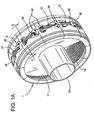
- a single form member 34 is shown as removed from the drum 7.
- the term "form” can refer to a single form member 34 or to a collection of form members, such as the form members which extend around the complete circumference of the drum 7.
- a single form member (not shown) extending around the entire circumference of the drum 7 could be employed.
- the illustrated form member 34 comprises outer side walls 51 connected to end walls 53 to form a rectangular frame.
- the side walls 51 are curved along their length to match the arc of the drum 7 over which the individual form members 34 will extend.
- Transverse walls 55 extend between the side walls 51 and longitudinal walls 57 extend between the end walls 53 inside the frame.
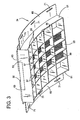
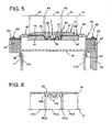
- the frame supports the forming surface 5 which in the illustrated embodiment comprises a honeycombed support 59 and a thin, perforated plate 61 (see Fig. 5 ).
- the support 59 and perforated plate 61 have the same upper surface shape.
- the support 59 underlies and provides strength for the perforated plate 61 to hold it in a fixed configuration under the load applied by the vacuum.
- the support 59 permits air to pass freely through it by virtue of the relative larger openings of its honeycomb structure.
- the openings can have any desired cross-sectional shape, such as circular, oval, hexagonal, pentagonal, other polygonal shape or the like, as well as combinations thereof, and need not be in a honeycomb arrangement.
- Such support structures are well known in the art, and can be composed of various materials, such as plastic, metal, ceramics and the like, as well as combinations thereof.
- the smaller holes in the perforated plate 61 also allow passage of air, but are sized to capture the fibrous material and prevent its passage through the forming surface 5.
- the perforate plate 61 may be replaced by a screen, a wire mesh, a hard-wire cloth or the like, as well as combinations thereof. It is envisioned that if a sufficiently rigid, self-supporting material could be found for the perforate plate 61, the support 59 could be omitted.
- Masking plates 63 are attached to the radially outwardly facing surface of the form member 34 to mask portions of the perforated plate 61 and support 59 to prevent air from passing through the masked portions and hence prevent deposition of fibrous material.
- the patterns 36 are defined by the shape of the masking plates 63.
- the form member 34 is mounted on the drum 7 by a pair of wings 65 attached to and extending laterally outwardly from respective side walls 51. When applied to the drum 7 as shown in Fig. 2 , the wings 65 of the form member 34 overlie respective, axially spaced mounting rings 67 mounted on the rim 18 at its opposite lateral edges.
- the form member 34 is releasably secured to the mounting rings 67 by bolts 69 passing through elongate openings 71 in the wings and threadably received in holes (not shown) formed in the rings.
- the elongation of the openings 71 allows some variation in the circumferential position of the form member 34, facilitating placement of the forming members on the drum 7.
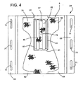
- the forming surface 5 has a length in the machine direction MD and a width in the cross direction CD and is shaped to include a first section 75 at a first depth below the top surface of the masking plate 63.
- the first section 75 is relatively shallow and planar in configuration for forming a thinner layer of fibrous material.
- the first section 75 is curved between the ends of the form member 34 in correspondence with the curvature of the drum 7.
- the first section 75 lies in a smooth surface and is substantially linear in cross section, as may be seen in Fig. 5 .
- the cross section is transverse to the extent of the form member 34 in the machine direction MD.
- the first section 75 may be irregular or have different depths over its area without departing from the scope of the present invention. In that event the "first depth" would be an average depth of the first section 75.
- a pocket, indicated generally at 77, includes a bottom surface 79 ("second section") and a transition surface 81 ("third section") connecting the first section 75 with the bottom surface.
- the terms "top” and “bottom” are used as convenient descriptors given the orientations illustrated in the drawings. However, these terms do not require any absolute orientation of the subject described.
- the first section 75 can include portions lying on both sides of the bottom surface 79, and in the illustrated embodiment the first section substantially surrounds the pocket 77.
- the bottom surface 79 (as shown in Figs. 4 and 5 ) has a generally undulating configuration which is everywhere below the surface containing the first section 75, and is non-linear in cross section.
- the bottom surface 79 has multiple ridges 83 extending in the machine direction MD the length of the pocket 77.
- the ridges 83 the (second) depth of the bottom surface 79 below the first section 75 varies over the area of the bottom surface.
- the ridges 83 located within the pocket 77 greatly increase the surface area within the pocket, reducing resistance to air flow (as compared to the first section 75) and thereby promoting the deposit of more fibrous material.
- the actual surface area of the bottom surface (or "second section") 79 is greater than an area P2 of the bottom surface (or second section) 79 projected onto a generally planar surface S lying directly above the forming surface 5.
- the surface S is generally planar, in fact it has a curvature corresponding to the curvature of the forming surface 5 along its length.
- the surface area of the bottom surface 79 is measure along its undulating extent over the ridges 83 and so is clearly larger than the projected area P2.
- Figure 5 also illustrates the projected area P1 of the first section 75 and the projected area P3 of the transition surface (third section) 81 onto the surface S.
- the projected areas P1 and P3 are shown to more particularly delineate the projected area P2.
- the actual surface area of the bottom surface 79 is at least about 10% larger than the projected surface area P2.
- a liquid holding formation 38A of the absorbent core has its full specified thickness and an upper surface 84 which is substantially flat. In other words, there is no dip in the upper surface 84 of the scarfed absorbent core 38 in the area of the liquid holding formation 38A caused by inadequate deposition of fibrous material in the pocket 77 of the forming surface 5.
- the liquid holding formation 38A has a sufficiently high basis weight and entanglement of the fibers in the formation is enhanced.
- the screen side of the liquid holding formation 38A (i.e., the side which engages the forming surface 5 when formed) is formed by the ridges 83 to have two channels 40 extending the length of the pocket 77.
- the surface area of the liquid holding formation 38A on the screen side of the absorbent core 38 is augmented by the shape given to it by the ridges 83 of the forming surface 5.
- Figure 6 illustrates the projection of various surfaces of the absorbent core 38 onto a planar surface S'.
- the projected area of the absorbent core 38 which was formed by the bottom surface 79 of the forming surface 5 is indicated at PC2
- the projected area of the core which was formed by the first section 75 is indicated at PC1
- the projected area of the core which was formed by the transition surface 81 is indicated at PC3.
- the projected area PC1 would be about the same as the surface area of the part of the absorbent core 38 which was formed by the first section 75 (in the illustrated embodiment).
- the projected area PC3 would be less than the surface area of the part of the absorbent core 38 formed by the transitional surface 81. It will be understood that the actual surface area of that part of the absorbent core formed by the bottom surface 79 will be larger than the projected area PC2 because of the additional surface area provided by the channels 40. For example, the surface area of the part of the absorbent core formed by the bottom surface 79 might be 10% larger than the projected area PC2.
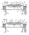
- a second, modified version of the forming surface 5' is shown in Figs. 7 and 8 . Corresponding parts of the second, modified version of the forming surface 5' will be indicated by the same reference numerals as for the first version of the forming surface 5, followed by a prime.
- the forming surface 5' includes a first section 75' substantially the same as the first section 75 of the forming surface 5 of Figs. 4 and 5 .
- a transition surface 81' connects the first section 75' to the bottom surface 79'.
- the bottom surface 79' includes two steps 85 extending in the machine-direction MD of the pocket 77'. The provision of the stepped bottom surface 79' within the pocket 77' increases the surface area of the pocket so that more fibrous material will be deposited in the pocket before the region of the perforated plate 61 within the pocket becomes clogged with fibrous material.
- a third, modified version of the forming surface 5'' is shown in Fig. 9 .
- Corresponding parts of the third, modified version of the forming surface 5'' will be indicated by the same reference numerals as for the first version of the forming surface 5, followed by a double prime.
- the forming surface 5'' includes a first section 75'' substantially the same as the first section of the forming surface 5 of Figs. 4 and 5 .
- the bottom surface 79'' is domed in shape and is a smooth curve in transverse cross section. The provision of the dome shape within the pocket 77'' increases the surface area of the pocket.
- the transition surface 81'' is located at the boundary between the first section 75'' and the bottom surface 79'', but lies in the same smooth surface as the bottom surface.
- the web can be debulked at a debulking station.
- various conventional devices and techniques can be employed to sever fibrous web 3 into predetermined lengths to provide selected air formed fibrous articles.
- the severing system may, for example, include a die cutter, a water cutter, rotary knives, reciprocating knives, energy beam cutters, particle beam cutters or the like, as well as combinations thereof. After severing, the discrete fibrous pads can be transported and delivered for further processing operations, as desired.
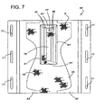
- an absorbent core 87 manufactured using a form having a forming surface (not shown) of the same general type as the forming surface 5 is shown with its screen side facing up so that its liquid holding formation 89 projects out of the page.
- the absorbent core 87 is shown in the orientation it would occupy leaving the forming drum (e.g., drum 7), which is inverted from the position in which the core is formed at the top of the drum.
- the forming surface used to make the absorbent core 87 has shapes in its pocket so that the screen side of liquid holding formation 89 of the absorbent core 87 is formed with plural channels 91 extending generally longitudinally of the liquid holding formation. As used herein "generally longitudinally” does not exclude some lateral extension of the channels (not shown).
- the liquid holding formation 89 is surrounded by a thinner outer region 94 also forming part of the absorbent core 87.
- the channels 91 facilitate distribution of fluid in the liquid holding formation 89.
- the channels 91 terminate prior to reaching a peripheral edge 93 of the liquid holding formation 89 which surrounds the channels. This construction helps prevent the fluids from running in the channels 91 completely off of the liquid holding formation 89 before they are absorbed,
- the channels 91 are formed by ridges on the bottom surface of the forming surface which are closely similar to the ridges 83 shown in Figs. 4 and 5 which formed the channels 40 of the liquid holding formation 38A. However, the ridges stop short of a transition surface (similar to transition surface 81) in the pocket, thereby spacing the ends of the channels 91 from the edge of the liquid holding formation 89.
Landscapes
- Health & Medical Sciences (AREA)
- Engineering & Computer Science (AREA)
- Life Sciences & Earth Sciences (AREA)
- Biomedical Technology (AREA)
- Heart & Thoracic Surgery (AREA)
- Vascular Medicine (AREA)
- Epidemiology (AREA)
- Animal Behavior & Ethology (AREA)
- General Health & Medical Sciences (AREA)
- Public Health (AREA)
- Veterinary Medicine (AREA)
- Manufacturing & Machinery (AREA)
- Absorbent Articles And Supports Therefor (AREA)
- Nonwoven Fabrics (AREA)
- Orthopedics, Nursing, And Contraception (AREA)
Claims (2)
- Verfahren zum Formen eines absorptionsfähigen Kerns (87), welcher eine längliche Flüssigkeitshalteanordnung (89) mit einem peripheren Rand (93) umfasst, wobei die Flüssigkeitshalteanordnung (89) eine Oberfläche aufweist, die mit Kanälen (91) in dem Kern (87) gebildet ist zur Verwendung bei der Verteilung von Flüssigkeit entlang des Kerns (87), wobei die Enden der Kanäle (91) an einem Ort enden, der nach innen von dem peripheren Rand (93) der Flüssigkeitshalteanordnung (89) beabstandet ist, um einen Fluss von Flüssigkeit in den Kanälen (91) über den peripheren Rand (93) der Flüssigkeitshalteanordnung (89) zu verhindern, wobei die Flüssigkeitshalteanordnung (89) die Kanäle (91) umgibt, dadurch gekennzeichnet, dass der absorptionsfähige Kern (87) des Weiteren einen äußeren Bereich (94) aus Fasermaterial aufweist, der außerhalb des peripheren Rands (93) der Flüssigkeitshalteanordnung (89) angeordnet ist, wobei der äußere Bereich (94) dünner ist als die Flüssigkeitshalteanordnung (89) und die Flüssigkeitshalteanordnung (89) umgibt, wobei die Kanäle (91) sich im Allgemeinen längs des Kerns (87) erstrecken und der Kern (87) und die Kanäle luftgeformt aus Fasermaterial sind, wobei das Verfahren Formen des Kerns unter Verwendung einer Form mit einer Formungsoberfläche, die eine Tasche beinhaltet, aufweist, wobei die Kanäle durch Grate auf einer Bodenoberfläche der Formungsoberfläche geformt werden.
- Verfahren gemäß Anspruch 1, wobei die Flüssigkeitshalteanordnung (89) eine Oberfläche aufweist, die um mindestens ungefähr 10% größer ist als eine projizierte Oberfläche der Flüssigkeitshalteanordnung (89).
Applications Claiming Priority (2)
| Application Number | Priority Date | Filing Date | Title |
|---|---|---|---|
| US10/207,929 US7001167B2 (en) | 2002-07-30 | 2002-07-30 | Apparatus and form for making an air formed fibrous web |
| EP20030736996 EP1524955B1 (de) | 2002-07-30 | 2003-06-10 | Einrichtung und form für die herstellung eines luftgelegten vliesstoffes |
Related Parent Applications (1)
| Application Number | Title | Priority Date | Filing Date |
|---|---|---|---|
| EP20030736996 Division EP1524955B1 (de) | 2002-07-30 | 2003-06-10 | Einrichtung und form für die herstellung eines luftgelegten vliesstoffes |
Publications (4)
| Publication Number | Publication Date |
|---|---|
| EP1920743A2 EP1920743A2 (de) | 2008-05-14 |
| EP1920743A3 EP1920743A3 (de) | 2008-08-06 |
| EP1920743B1 EP1920743B1 (de) | 2012-09-05 |
| EP1920743B2 true EP1920743B2 (de) | 2015-11-04 |
Family
ID=31186741
Family Applications (2)
| Application Number | Title | Priority Date | Filing Date |
|---|---|---|---|
| EP08001169.5A Expired - Lifetime EP1920743B2 (de) | 2002-07-30 | 2003-06-10 | Luftgeformtes Fasernetz |
| EP20030736996 Expired - Lifetime EP1524955B1 (de) | 2002-07-30 | 2003-06-10 | Einrichtung und form für die herstellung eines luftgelegten vliesstoffes |
Family Applications After (1)
| Application Number | Title | Priority Date | Filing Date |
|---|---|---|---|
| EP20030736996 Expired - Lifetime EP1524955B1 (de) | 2002-07-30 | 2003-06-10 | Einrichtung und form für die herstellung eines luftgelegten vliesstoffes |
Country Status (5)
| Country | Link |
|---|---|
| US (3) | US7001167B2 (de) |
| EP (2) | EP1920743B2 (de) |
| JP (1) | JP4613064B2 (de) |
| AU (1) | AU2003237973A1 (de) |
| WO (1) | WO2004011723A2 (de) |
Cited By (1)
| Publication number | Priority date | Publication date | Assignee | Title |
|---|---|---|---|---|
| US9375358B2 (en) | 2012-12-10 | 2016-06-28 | The Procter & Gamble Company | Absorbent article with high absorbent material content |
Families Citing this family (85)
| Publication number | Priority date | Publication date | Assignee | Title |
|---|---|---|---|---|
| EP1911425B1 (de) | 2003-02-12 | 2014-01-15 | The Procter and Gamble Company | Saugfähiger Kern für einen saugfähigen Artikel |
| DE60323810D1 (de) | 2003-02-12 | 2008-11-13 | Procter & Gamble | Bequem Windel |
| US20050148258A1 (en) * | 2003-12-31 | 2005-07-07 | Jayant Chakravarty | Absorbent structures having enhanced flexibility |
| US7099791B2 (en) * | 2004-05-21 | 2006-08-29 | Credence Systems Corporation | System and method for linking and loading compiled pattern data |
| JP4580736B2 (ja) * | 2004-11-18 | 2010-11-17 | ユニ・チャーム株式会社 | 吸液性芯材成型ドラム |
| US7687012B2 (en) * | 2005-08-30 | 2010-03-30 | Kimberly-Clark Worldwide, Inc. | Method and apparatus to shape a composite structure without contact |
| US7682554B2 (en) | 2005-08-30 | 2010-03-23 | Kimberly-Clark Worldwide, Inc. | Method and apparatus to mechanically shape a composite structure |
| US7553146B2 (en) * | 2006-11-15 | 2009-06-30 | The Procter & Gamble Company | Apparatus for making air-laid structures |
| US7549853B2 (en) * | 2006-11-15 | 2009-06-23 | The Procter & Gamble Company | Apparatus for making air-laid structures |
| US7704441B2 (en) * | 2006-11-15 | 2010-04-27 | The Procter & Gamble Company | Method for making air-laid structures |
| US7704439B2 (en) * | 2006-11-15 | 2010-04-27 | The Procter & Gamble Company | Method for making air-laid structures |
| US7827464B2 (en) * | 2006-11-15 | 2010-11-02 | Seagate Technology Llc | Iterative read channel architectures with coded modulation |
| GB2460727B (en) | 2007-06-18 | 2012-04-11 | Procter & Gamble | Disposable absorbent article with substantially continously distributed absorbent particulate polymer material and method |
| MX2009013906A (es) | 2007-06-18 | 2010-01-28 | Procter & Gamble | Articulo absorbente desechable con nucleo absorbente sellado con material polimerico particulado absorbente practicamente distribuido en forma continua. |
| JP4820333B2 (ja) * | 2007-06-22 | 2011-11-24 | 花王株式会社 | 吸収体の製造装置 |
| WO2009134780A1 (en) | 2008-04-29 | 2009-11-05 | The Procter & Gamble Company | Process for making an absorbent core with strain resistant core cover |
| US7994385B2 (en) | 2008-08-05 | 2011-08-09 | Johnson & Johnson Ind. E Com. Ltda | Absorbent article including absorbent core having concentrically arranged absorbent regions |
| US20100032860A1 (en) * | 2008-08-05 | 2010-02-11 | Hernandez Francisco J V | Method for making an absorbent core having concentrically arranged absorbent regions |
| US8871123B2 (en) * | 2008-08-05 | 2014-10-28 | Johnson & Johnson Ind. E Com. Ltda. | Method of making an absorbent core having a plurality of first regions and a second region surrounding each of the first regions |
| US8093448B2 (en) | 2008-08-05 | 2012-01-10 | Johnson & Johnson Ind. E. Com LTDA | Absorbent article including absorbent core having a plurality of first regions and a second region surrounding each of the first regions |
| EP2329803B1 (de) | 2009-12-02 | 2019-06-19 | The Procter & Gamble Company | Vorrichtungen und verfahren zum transportieren von teilchenförmigem material |
| JP5296663B2 (ja) * | 2009-12-04 | 2013-09-25 | 花王株式会社 | 吸収体の製造方法及び製造装置 |
| WO2011068062A1 (ja) * | 2009-12-04 | 2011-06-09 | 花王株式会社 | 吸収体の製造方法及び製造装置 |
| US8480387B2 (en) | 2010-08-12 | 2013-07-09 | Johnson & Johnson Do Brasil Industria E Comercio Produtos Para Saude Ltda. | Apparatus for making a fibrous article having a three dimensional profile |
| US8394316B2 (en) | 2010-08-12 | 2013-03-12 | Johnson & Johnson Do Brasil Industria E Comercio Produtos Para Saude Ltda. Rodovia | Method for making a fibrous article |
| US8388329B2 (en) | 2010-08-12 | 2013-03-05 | Johnson & Johnson Do Brasil Industria E Comercio Produtos Para Saude Ltda. Rodovia | Apparatus for making a fibrous article |
| US8398915B2 (en) | 2010-08-12 | 2013-03-19 | Johnson & Johnson do Brasil Industria e Comercio Produtos Paral Saude Ltda. Rodovia | Method for making a fibrous article |
| ITAP20100013A1 (it) * | 2010-09-24 | 2012-03-25 | Mir S R L | Stampi di formazione per fluff di cellulosa, defibrata e/o macinata meccanicamente |
| JP5765909B2 (ja) * | 2010-09-30 | 2015-08-19 | ユニ・チャーム株式会社 | 積繊装置の回転ドラム |
| RU2568565C2 (ru) | 2011-06-10 | 2015-11-20 | Дзе Проктер Энд Гэмбл Компани | Одноразовые подгузники |
| EP2532329B1 (de) * | 2011-06-10 | 2018-09-19 | The Procter and Gamble Company | Verfahren und vorrichtung zum herstellen von absorptionsstrukturen mit absorptionsmaterial |
| EP3287110B1 (de) | 2011-06-10 | 2019-03-20 | The Procter and Gamble Company | Verfahren zur herstellung von saugfähigen strukturen für saugfähige artikel |
| EP2532332B2 (de) | 2011-06-10 | 2017-10-04 | The Procter and Gamble Company | Einwegwindel mit reduzierter Befestigung zwischen saugfähigem Kern und äusserer Schicht |
| BR112013030599A2 (pt) | 2011-06-10 | 2016-09-27 | Procter & Gamble | núcleo absorvente para artigos absorventes descartáveis |
| PH12013502575A1 (en) | 2011-06-10 | 2014-02-10 | Procter & Gamble | Absorbent structure for absorbent articles |
| PL2532328T3 (pl) | 2011-06-10 | 2014-07-31 | Procter & Gamble | Sposób i urządzenie do wytworzenia struktur chłonnych z materiałem chłonnym |
| CN104780885A (zh) | 2012-11-13 | 2015-07-15 | 宝洁公司 | 具有通道和标志的吸收制品 |
| US9216118B2 (en) | 2012-12-10 | 2015-12-22 | The Procter & Gamble Company | Absorbent articles with channels and/or pockets |
| US9216116B2 (en) | 2012-12-10 | 2015-12-22 | The Procter & Gamble Company | Absorbent articles with channels |
| US10639215B2 (en) | 2012-12-10 | 2020-05-05 | The Procter & Gamble Company | Absorbent articles with channels and/or pockets |
| US8979815B2 (en) | 2012-12-10 | 2015-03-17 | The Procter & Gamble Company | Absorbent articles with channels |
| EP2740450A1 (de) | 2012-12-10 | 2014-06-11 | The Procter & Gamble Company | Saugfähiger Artikel mit hohem Anteil an Superabsorptionsmaterial |
| EP2740452B1 (de) | 2012-12-10 | 2021-11-10 | The Procter & Gamble Company | Saugfähiger Artikel mit hohem Anteil an Absorptionsmaterial |
| PL2813201T3 (pl) | 2013-06-14 | 2018-04-30 | The Procter And Gamble Company | Wyrób chłonny i wkład chłonny tworzący kanały w stanie mokrym |
| US9987176B2 (en) | 2013-08-27 | 2018-06-05 | The Procter & Gamble Company | Absorbent articles with channels |
| MX2016002608A (es) | 2013-08-27 | 2016-06-17 | Procter & Gamble | Articulos absorbentes con canales. |
| MX2016003391A (es) | 2013-09-16 | 2016-06-24 | Procter & Gamble | Articulos absorbentes con canales y señales. |
| US11207220B2 (en) | 2013-09-16 | 2021-12-28 | The Procter & Gamble Company | Absorbent articles with channels and signals |
| EP2851048B1 (de) | 2013-09-19 | 2018-09-05 | The Procter and Gamble Company | Absorbierende Kerne mit materialfreien Bereichen |
| US9789009B2 (en) | 2013-12-19 | 2017-10-17 | The Procter & Gamble Company | Absorbent articles having channel-forming areas and wetness indicator |
| ES2606320T3 (es) | 2013-12-19 | 2017-03-23 | The Procter & Gamble Company | Núcleos absorbentes que tienen áreas formadoras de canal y juntas de envoltura en c |
| EP2905001B1 (de) | 2014-02-11 | 2017-01-04 | The Procter and Gamble Company | Verfahren und Vorrichtung zum Herstellen von absorbierenden Strukturen mit Kanälen |
| EP2949301B1 (de) | 2014-05-27 | 2018-04-18 | The Procter and Gamble Company | Saugfähiger Kern mit gebogenen und geraden Absorptionsmaterialbereichen |
| EP2949300B1 (de) | 2014-05-27 | 2017-08-02 | The Procter and Gamble Company | Saugfähiger Kern mit saugfähiger Materialstruktur |
| EP2949302B1 (de) | 2014-05-27 | 2018-04-18 | The Procter and Gamble Company | Saugfähiger Kern mit gebogenen, kanalbildenden Bereichen |
| PL2949299T3 (pl) | 2014-05-27 | 2018-01-31 | Procter & Gamble | Wkład chłonny z układem rozmieszczenia materiału chłonnego |
| MX367745B (es) | 2015-01-23 | 2019-09-03 | Kimberly Clark Co | Estructura absorbente entrelazada. |
| CN107405223B (zh) | 2015-03-16 | 2021-03-02 | 宝洁公司 | 具有改善的强度的吸收制品 |
| JP2018508292A (ja) | 2015-03-16 | 2018-03-29 | ザ プロクター アンド ギャンブル カンパニー | 改善されたコアを有する吸収性物品 |
| CA2985807A1 (en) | 2015-05-12 | 2016-11-17 | The Procter & Gamble Company | Absorbent article with improved core-to-backsheet adhesive |
| WO2016196069A1 (en) | 2015-05-29 | 2016-12-08 | The Procter & Gamble Company | Absorbent articles having channels and wetness indicator |
| KR101587463B1 (ko) * | 2015-06-02 | 2016-02-02 | 주식회사 영농 | 부직포 원료의 정렬 장치 |
| KR101565412B1 (ko) * | 2015-06-08 | 2015-11-03 | (주) 영농 | 복수의 부직포 원료의 정렬 장치에 의해 부직포의 층수 및 두께의 제어가 가능한 부직포 제조 시스템 및 이에 의해 만들어진 부직포 |
| CN106389005A (zh) * | 2015-07-28 | 2017-02-15 | 天津市海正泰克塑胶制品有限公司 | 带压模的三角巾压和机构 |
| MX377934B (es) | 2015-10-30 | 2025-03-11 | Kimberly Clark Co | Articulo absorbente con canales y miembros elasticos de conformacion. |
| EP3167859B1 (de) | 2015-11-16 | 2020-05-06 | The Procter and Gamble Company | Absorbierende kerne mit materialfreien bereichen |
| EP3238678B1 (de) | 2016-04-29 | 2019-02-27 | The Procter and Gamble Company | Saugfähiger kern mit transversalen faltlinien |
| EP3238676B1 (de) | 2016-04-29 | 2019-01-02 | The Procter and Gamble Company | Saugkern mit profilierter verteilung von absorbierendem material |
| IT201700031317A1 (it) | 2017-03-22 | 2018-09-22 | Gdm Spa | Apparato e metodo di formatura di una imbottitura assorbente. |
| EP3473222B1 (de) | 2017-10-23 | 2021-08-04 | The Procter & Gamble Company | Absorbierende artikel mit verschiedenartigen kanälen |
| EP3473224B1 (de) | 2017-10-23 | 2020-12-30 | The Procter & Gamble Company | Absorbierende artikel mit verschiedenartigen kanälen |
| EP3473223B1 (de) | 2017-10-23 | 2021-08-11 | The Procter & Gamble Company | Absorbierende artikel mit verschiedenartigen kanälen |
| IT201800002184A1 (it) * | 2018-01-30 | 2019-07-30 | Gdm Spa | Dispositivo di formatura di un’ imbottitura assorbente |
| EP3560466B1 (de) | 2018-04-27 | 2023-08-23 | The Procter & Gamble Company | Absorbierende artikel mit mehrteiliger aufnahmeschicht |
| EP3560465A1 (de) | 2018-04-27 | 2019-10-30 | The Procter & Gamble Company | Artikel mit einer aufnahmeschicht mit strecköffnungen und verfahren zur herstellung davon |
| EP3613394B1 (de) | 2018-08-21 | 2023-07-26 | The Procter & Gamble Company | Verfahren zur herstellung von faserschichten mit kanälen für absorbierende artikel |
| JP7352006B2 (ja) | 2019-07-19 | 2023-09-27 | エシティ・ハイジーン・アンド・ヘルス・アクチエボラグ | 交互に存在する吸収性材料高密度領域および吸収性材料低密度領域を有するコアを備える吸収性製品 |
| US12097098B2 (en) | 2019-07-19 | 2024-09-24 | Essity Hygiene And Health Akitebolag | Absorbent article |
| EP3944844B1 (de) | 2020-07-30 | 2023-08-23 | The Procter & Gamble Company | Absorbierende artikel mit klebestreifen mit vorder- und schrittkanälen |
| USD979047S1 (en) | 2021-06-17 | 2023-02-21 | Medline Industries, Lp | Absorbent article with channeled core |
| USD979747S1 (en) | 2021-06-17 | 2023-02-28 | Medline Industries, Lp | Absorbent article with channeled core |
| USD978341S1 (en) | 2021-06-17 | 2023-02-14 | Medline Industries, Lp | Absorbent article with channeled core |
| USD979046S1 (en) | 2021-06-17 | 2023-02-21 | Medline Industries, Lp | Absorbent article with channeled core |
| CN113604972B (zh) * | 2021-10-08 | 2021-11-30 | 南通语森家纺科技有限公司 | 用于工业纺织毛毡的制毡加工装置 |
| EP4613932A1 (de) * | 2024-03-07 | 2025-09-10 | COAX Technologies S.r.l. | Luftablage- verfahren und vorrichtung zur herstellung von bahnen mit scharf definierten seitenkanten |
Citations (8)
| Publication number | Priority date | Publication date | Assignee | Title |
|---|---|---|---|---|
| US3860002A (en) † | 1973-05-14 | 1975-01-14 | Scott Paper Co | Absorbent articles |
| US4685915A (en) † | 1984-04-06 | 1987-08-11 | The Procter & Gamble Company | Disposable diaper having density and basis weight profiled absorbent core |
| GB2191098A (en) † | 1986-06-07 | 1987-12-09 | Smith & Nephew Ass | Sanitary towels |
| EP0788874A1 (de) † | 1996-02-12 | 1997-08-13 | McNEIL-PPC, Inc. | Schichtverbundmaterial, Verfahren zur Herstellung und davon abgeleitete Produkten |
| US5795344A (en) † | 1996-12-20 | 1998-08-18 | Kimberly-Clark Worldwide, Inc. | Absorbent article with protection channel |
| EP1008333A2 (de) † | 1998-12-11 | 2000-06-14 | Uni-Charm Corporation | Absorbierender Wegwerfartikel für Körperflüssigkeiten |
| GB2354449A (en) † | 1996-11-29 | 2001-03-28 | Kao Corp | An absorbent article with grooves |
| EP1210925A2 (de) † | 2000-11-30 | 2002-06-05 | Uni-Charm Corporation | Wegwerfwindel |
Family Cites Families (29)
| Publication number | Priority date | Publication date | Assignee | Title |
|---|---|---|---|---|
| US3749627A (en) * | 1971-03-29 | 1973-07-31 | J Jones | Reservoir napkin manufacturing process |
| US4005957A (en) * | 1974-05-16 | 1977-02-01 | Scott Paper Company | Apparatus for forming fibrous pads |
| US4059114A (en) * | 1976-05-12 | 1977-11-22 | Minnesota Mining And Manufacturing Company | Garment shield |
| US4154883A (en) * | 1976-10-20 | 1979-05-15 | Johnson & Johnson | Emboss laminated fibrous material |
| US4674966A (en) * | 1984-04-02 | 1987-06-23 | Winkler & Dunnebier | Apparatus for forming fibrous pads |
| US4585448A (en) * | 1984-12-19 | 1986-04-29 | Kimberly-Clark Corporation | Disposable garment having high-absorbency area |
| EP0226939B1 (de) * | 1985-12-10 | 1992-11-19 | Kimberly-Clark Corporation | Vorrichtung und Verfahren für die Erzeugung eines Faservlieses |
| US4761258A (en) * | 1985-12-10 | 1988-08-02 | Kimberly-Clark Corporation | Controlled formation of light and heavy fluff zones |
| US4666647A (en) * | 1985-12-10 | 1987-05-19 | Kimberly-Clark Corporation | Apparatus and process for forming a laid fibrous web |
| US4927582A (en) * | 1986-08-22 | 1990-05-22 | Kimberly-Clark Corporation | Method and apparatus for creating a graduated distribution of granule materials in a fiber mat |
| US4952128A (en) * | 1987-09-22 | 1990-08-28 | Chicopee | Transverse web forming apparatus |
| US5076774A (en) | 1989-02-16 | 1991-12-31 | Chicopee | Apparatus for forming three dimensional composite webs |
| HU903574D0 (en) * | 1989-05-05 | 1991-07-29 | Progesan S R L | Apparatus for creating hygienic products |
| US5451442A (en) * | 1991-12-17 | 1995-09-19 | Paragon Trade Brands, Inc. | Absorbent panel structure for a disposable garment |
| US5540872A (en) * | 1992-12-31 | 1996-07-30 | Mcneil-Ppc, Inc. | Method and system for making three-dimensional fabrics |
| IL104929A (en) * | 1993-03-03 | 1995-11-27 | Tafnukim Amir Paper Products | Preparation of an absorbent sheet |
| US5466409A (en) * | 1993-10-19 | 1995-11-14 | Kimberly-Clark Corporation | Forming belt for three-dimensional forming applications |
| EP0700673B1 (de) | 1994-09-09 | 2002-03-27 | The Procter & Gamble Company | Methode zur Herstellung einer absorbierenden Struktur |
| US5853628A (en) * | 1996-09-12 | 1998-12-29 | Kimberly-Clark Worldwide, Inc. | Method of forming nonwoven fabric having a pore size gradient |
| DE19713189A1 (de) * | 1997-03-27 | 1998-10-01 | Kimberly Clark Gmbh | Absorbierender Artikel |
| US6098249A (en) * | 1997-10-29 | 2000-08-08 | Toney; Jerry L. | Apparatus for forming controlled density fibrous pads for diapers and the other absorbent products |
| BR9900001A (pt) * | 1999-01-04 | 2000-08-29 | Johnson & Johnson Ind Com | Artigo absorvente descartável |
| JP3541144B2 (ja) * | 1999-05-31 | 2004-07-07 | ユニ・チャーム株式会社 | 便処理用の使い捨て着用物品 |
| US6319455B1 (en) * | 1999-08-13 | 2001-11-20 | First Quality Nonwovens, Inc. | Nonwoven fabric with high CD elongation and method of making same |
| KR20020035611A (ko) | 1999-09-21 | 2002-05-11 | 오그덴 브라이언 씨 | 홈붙이 흡수성 복합물 |
| US6488670B1 (en) | 2000-10-27 | 2002-12-03 | Kimberly-Clark Worldwide, Inc. | Corrugated absorbent system for hygienic products |
| US6330735B1 (en) * | 2001-02-16 | 2001-12-18 | Kimberly-Clark Worldwide, Inc. | Apparatus and process for forming a laid fibrous web with enhanced basis weight capability |
| BR0105724B1 (pt) * | 2001-11-26 | 2010-11-30 | absorvente higiênico. | |
| EP1583493B1 (de) * | 2002-12-31 | 2015-05-06 | BSN medical GmbH | Wundauflage |
-
2002
- 2002-07-30 US US10/207,929 patent/US7001167B2/en not_active Expired - Lifetime
-
2003
- 2003-06-10 AU AU2003237973A patent/AU2003237973A1/en not_active Abandoned
- 2003-06-10 EP EP08001169.5A patent/EP1920743B2/de not_active Expired - Lifetime
- 2003-06-10 WO PCT/US2003/018330 patent/WO2004011723A2/en not_active Ceased
- 2003-06-10 JP JP2004524508A patent/JP4613064B2/ja not_active Expired - Fee Related
- 2003-06-10 EP EP20030736996 patent/EP1524955B1/de not_active Expired - Lifetime
-
2005
- 2005-07-29 US US11/193,697 patent/US8178747B2/en active Active
-
2012
- 2012-03-28 US US13/432,500 patent/US8604270B2/en not_active Expired - Lifetime
Patent Citations (8)
| Publication number | Priority date | Publication date | Assignee | Title |
|---|---|---|---|---|
| US3860002A (en) † | 1973-05-14 | 1975-01-14 | Scott Paper Co | Absorbent articles |
| US4685915A (en) † | 1984-04-06 | 1987-08-11 | The Procter & Gamble Company | Disposable diaper having density and basis weight profiled absorbent core |
| GB2191098A (en) † | 1986-06-07 | 1987-12-09 | Smith & Nephew Ass | Sanitary towels |
| EP0788874A1 (de) † | 1996-02-12 | 1997-08-13 | McNEIL-PPC, Inc. | Schichtverbundmaterial, Verfahren zur Herstellung und davon abgeleitete Produkten |
| GB2354449A (en) † | 1996-11-29 | 2001-03-28 | Kao Corp | An absorbent article with grooves |
| US5795344A (en) † | 1996-12-20 | 1998-08-18 | Kimberly-Clark Worldwide, Inc. | Absorbent article with protection channel |
| EP1008333A2 (de) † | 1998-12-11 | 2000-06-14 | Uni-Charm Corporation | Absorbierender Wegwerfartikel für Körperflüssigkeiten |
| EP1210925A2 (de) † | 2000-11-30 | 2002-06-05 | Uni-Charm Corporation | Wegwerfwindel |
Cited By (1)
| Publication number | Priority date | Publication date | Assignee | Title |
|---|---|---|---|---|
| US9375358B2 (en) | 2012-12-10 | 2016-06-28 | The Procter & Gamble Company | Absorbent article with high absorbent material content |
Also Published As
| Publication number | Publication date |
|---|---|
| US8178747B2 (en) | 2012-05-15 |
| EP1524955A2 (de) | 2005-04-27 |
| WO2004011723A3 (en) | 2004-04-01 |
| US20120184934A1 (en) | 2012-07-19 |
| US7001167B2 (en) | 2006-02-21 |
| EP1524955B1 (de) | 2012-01-25 |
| WO2004011723A2 (en) | 2004-02-05 |
| EP1920743A3 (de) | 2008-08-06 |
| AU2003237973A8 (en) | 2004-02-16 |
| US20050261657A1 (en) | 2005-11-24 |
| EP1920743B1 (de) | 2012-09-05 |
| JP4613064B2 (ja) | 2011-01-12 |
| AU2003237973A1 (en) | 2004-02-16 |
| US20040023583A1 (en) | 2004-02-05 |
| JP2005534819A (ja) | 2005-11-17 |
| EP1920743A2 (de) | 2008-05-14 |
| US8604270B2 (en) | 2013-12-10 |
Similar Documents
| Publication | Publication Date | Title |
|---|---|---|
| EP1920743B2 (de) | Luftgeformtes Fasernetz | |
| EP1360361B1 (de) | Vorrichtung und verfahren zur bildung von luftgelegten faserbahnen mit verbesserter gewichtseigenschaft | |
| EP1423068B2 (de) | Mehrstufige drehbare vakuumtrommel | |
| US7568900B2 (en) | Apparatus for making a reinforced fibrous absorbent member | |
| US7094373B2 (en) | Process and apparatus for air forming an article having a plurality of reinforced superimposed fibrous layers | |
| EP1565138B1 (de) | Geregelte positionierung eines verstärkungsgewebes innerhalb eines saugfähiges fasergegenstandes | |
| KR102506164B1 (ko) | 브릿지형 흡수성 구조체 제조 방법 | |
| WO2004028426A1 (en) | Process and apparatus for air forming an article having a plurality of reinforced superimposed fibrous layers |
Legal Events
| Date | Code | Title | Description |
|---|---|---|---|
| PUAI | Public reference made under article 153(3) epc to a published international application that has entered the european phase |
Free format text: ORIGINAL CODE: 0009012 |
|
| AC | Divisional application: reference to earlier application |
Ref document number: 1524955 Country of ref document: EP Kind code of ref document: P |
|
| AK | Designated contracting states |
Kind code of ref document: A2 Designated state(s): DE FR IT NL SE |
|
| PUAL | Search report despatched |
Free format text: ORIGINAL CODE: 0009013 |
|
| AK | Designated contracting states |
Kind code of ref document: A3 Designated state(s): DE FR IT NL SE |
|
| 17P | Request for examination filed |
Effective date: 20090205 |
|
| 17Q | First examination report despatched |
Effective date: 20090310 |
|
| AKX | Designation fees paid |
Designated state(s): DE FR IT NL SE |
|
| GRAP | Despatch of communication of intention to grant a patent |
Free format text: ORIGINAL CODE: EPIDOSNIGR1 |
|
| RIC1 | Information provided on ipc code assigned before grant |
Ipc: A61F 13/532 20060101ALI20120131BHEP Ipc: A61F 13/15 20060101AFI20120131BHEP |
|
| RTI1 | Title (correction) |
Free format text: AIR FORMED FIBROUS WEB |
|
| GRAS | Grant fee paid |
Free format text: ORIGINAL CODE: EPIDOSNIGR3 |
|
| GRAA | (expected) grant |
Free format text: ORIGINAL CODE: 0009210 |
|
| AC | Divisional application: reference to earlier application |
Ref document number: 1524955 Country of ref document: EP Kind code of ref document: P |
|
| AK | Designated contracting states |
Kind code of ref document: B1 Designated state(s): DE FR IT NL SE |
|
| REG | Reference to a national code |
Ref country code: DE Ref legal event code: R096 Ref document number: 60342051 Country of ref document: DE Effective date: 20121025 |
|
| REG | Reference to a national code |
Ref country code: NL Ref legal event code: VDEP Effective date: 20120905 |
|
| PG25 | Lapsed in a contracting state [announced via postgrant information from national office to epo] |
Ref country code: SE Free format text: LAPSE BECAUSE OF FAILURE TO SUBMIT A TRANSLATION OF THE DESCRIPTION OR TO PAY THE FEE WITHIN THE PRESCRIBED TIME-LIMIT Effective date: 20120905 |
|
| PG25 | Lapsed in a contracting state [announced via postgrant information from national office to epo] |
Ref country code: NL Free format text: LAPSE BECAUSE OF FAILURE TO SUBMIT A TRANSLATION OF THE DESCRIPTION OR TO PAY THE FEE WITHIN THE PRESCRIBED TIME-LIMIT Effective date: 20120905 |
|
| PLBI | Opposition filed |
Free format text: ORIGINAL CODE: 0009260 |
|
| 26 | Opposition filed |
Opponent name: THE PROCTER & GAMBLE COMMPANY Effective date: 20130529 Opponent name: SCA HYGIENE PRODUCTS AB Effective date: 20130531 |
|
| PLAX | Notice of opposition and request to file observation + time limit sent |
Free format text: ORIGINAL CODE: EPIDOSNOBS2 |
|
| REG | Reference to a national code |
Ref country code: DE Ref legal event code: R026 Ref document number: 60342051 Country of ref document: DE Effective date: 20130529 |
|
| PLBB | Reply of patent proprietor to notice(s) of opposition received |
Free format text: ORIGINAL CODE: EPIDOSNOBS3 |
|
| REG | Reference to a national code |
Ref country code: FR Ref legal event code: ST Effective date: 20140228 |
|
| PG25 | Lapsed in a contracting state [announced via postgrant information from national office to epo] |
Ref country code: FR Free format text: LAPSE BECAUSE OF NON-PAYMENT OF DUE FEES Effective date: 20130701 |
|
| APBM | Appeal reference recorded |
Free format text: ORIGINAL CODE: EPIDOSNREFNO |
|
| APBP | Date of receipt of notice of appeal recorded |
Free format text: ORIGINAL CODE: EPIDOSNNOA2O |
|
| APAH | Appeal reference modified |
Free format text: ORIGINAL CODE: EPIDOSCREFNO |
|
| APBU | Appeal procedure closed |
Free format text: ORIGINAL CODE: EPIDOSNNOA9O |
|
| PUAH | Patent maintained in amended form |
Free format text: ORIGINAL CODE: 0009272 |
|
| STAA | Information on the status of an ep patent application or granted ep patent |
Free format text: STATUS: PATENT MAINTAINED AS AMENDED |
|
| 27A | Patent maintained in amended form |
Effective date: 20151104 |
|
| AK | Designated contracting states |
Kind code of ref document: B2 Designated state(s): DE FR IT NL SE |
|
| REG | Reference to a national code |
Ref country code: DE Ref legal event code: R102 Ref document number: 60342051 Country of ref document: DE |
|
| PGFP | Annual fee paid to national office [announced via postgrant information from national office to epo] |
Ref country code: IT Payment date: 20220621 Year of fee payment: 20 |
|
| PGFP | Annual fee paid to national office [announced via postgrant information from national office to epo] |
Ref country code: DE Payment date: 20220629 Year of fee payment: 20 |
|
| REG | Reference to a national code |
Ref country code: DE Ref legal event code: R071 Ref document number: 60342051 Country of ref document: DE |