EP1920648B1 - Aufnehmer für landwirtschaftliche Maschinen, insbesondere für Rundballenpressen - Google Patents
Aufnehmer für landwirtschaftliche Maschinen, insbesondere für Rundballenpressen Download PDFInfo
- Publication number
- EP1920648B1 EP1920648B1 EP07119310A EP07119310A EP1920648B1 EP 1920648 B1 EP1920648 B1 EP 1920648B1 EP 07119310 A EP07119310 A EP 07119310A EP 07119310 A EP07119310 A EP 07119310A EP 1920648 B1 EP1920648 B1 EP 1920648B1
- Authority
- EP
- European Patent Office
- Prior art keywords
- pickup device
- pickup
- transmission wheel
- transverse bars
- apt
- Prior art date
- Legal status (The legal status is an assumption and is not a legal conclusion. Google has not performed a legal analysis and makes no representation as to the accuracy of the status listed.)
- Active
Links
- 230000005540 biological transmission Effects 0.000 claims abstract description 30
- 239000000463 material Substances 0.000 claims abstract description 11
- 239000004459 forage Substances 0.000 claims abstract description 4
- 239000004463 hay Substances 0.000 claims abstract description 4
- 239000010902 straw Substances 0.000 claims abstract description 4
- 230000006835 compression Effects 0.000 description 2
- 238000007906 compression Methods 0.000 description 2
- 238000012986 modification Methods 0.000 description 2
- 230000004048 modification Effects 0.000 description 2
- 230000001681 protective effect Effects 0.000 description 2
- 230000015572 biosynthetic process Effects 0.000 description 1
- 230000000295 complement effect Effects 0.000 description 1
- 238000012423 maintenance Methods 0.000 description 1
- 230000002093 peripheral effect Effects 0.000 description 1
- 239000002699 waste material Substances 0.000 description 1
Images


Classifications
-
- A—HUMAN NECESSITIES
- A01—AGRICULTURE; FORESTRY; ANIMAL HUSBANDRY; HUNTING; TRAPPING; FISHING
- A01D—HARVESTING; MOWING
- A01D89/00—Pick-ups for loaders, chaff-cutters, balers, field-threshers, or the like, i.e. attachments for picking-up hay or the like field crops
- A01D89/001—Pick-up systems
- A01D89/002—Rotors
Definitions
- the present invention relates to a pickup device, suitable for agricultural machines, in particular round balers, apt to pick up tiers of straw, hay, forages and similar materials and to the compression of such products in bales with rectangular or round section.
- balers In agriculture, the use of round balers for the pick-up of mown materials and the compression thereof in bales is very widespread.
- such machines usually in the front position, have a pickup device picking up the mown materials from the ground and conveying them, directly or through other members, to a bale-forming chamber arranged above such pickup device.
- the pickup device is as wide as possible, so that the mown material on the whole width of each tier can be picked up with a single run.
- the pickup devices built according to the known art are usually equipped with small wheels, which are fastened to the pickup device itself.
- Such wheels are adjustable and allow the pickup device to follow the ground unevenesses. From the practice it is known that the most effective location for such wheels is next to the transverse axis of rotation of the pickup device itself. Consequently, such wheels cannot be effectively arranged in front of the pickup body, but, on the contrary, they are usually arranged on the sides of the pickup body itself.
- the road transportation in accordance with the laws in force in Italy, imposes the width of the round baler machine not to exceed 2.55 meters. Such limit represents a constraint for the maximum width of the pickup device too.
- the pickup device exceeds the abovementioned size, it should be disassembled prior to road transportation and subsequently it should be assembled again onto the round baler prior to a new pick-up operation on the field. This disassembling and assembling operation is complex and toilsome, thus it should be avoided, if possible.
- the pickup devices of the known agricultural machines have such a system that allows the abovementioned wheels to be easily removed from the working position and placed elsewhere, so that the pickup device, once deprived of the wheels, does not exceed the abovementioned maximum width of 2.55 meters, thus complying with the laws in force. Nevertheless, however easier it may be, also the disassembling and assembling operation of the sensing wheels is toilsome. In practice, often such disassembling is not performed, as it is considered a useless waste of time, and the consequent road transportation of the round baler machine represents a potential danger for the road traffic, as it brakes the rules.
- such devices use a plurality of teeth which are supported by transverse bars, which cause a roto-translational motion to the teeth by means of a cam-like system, so as to perform the pick-up operation.
- the object of the present invention is to provide a pickup device for agricultural machines, in particular round balers, apt to pick up tiers of straw, hay, forages and similar materials, comprising a central shaft, at least two transverse bars bearing a plurality of teeth, two side heads integral to the central shaft bearing said at least two transverse bars constituting a pickup body, supports allowing the rotation of said pickup body around an axis which is parallel to said at least two transverse bars, and at least one transmission wheel integral to said pickup body, characterized in that said at least one transmission wheel is directly adjacent to one of said side heads and it is fastened to said head by means of mechanical connection members.
- Another object of the present invention is to provide a pickup device which, the usable pickup size being the same, has transversal dimensions that are smaller than those of the known art devices, so that the maximum width provided by the law for the road transportation is complied with by the present invention without disassemblement of any members or any other kind of intervention type being needed.
- an other object of the present invention is to avoid the use of distinct transmission members for the rotational motion and for the rotational motion of the teeth implementing the pick-up operation.
- an additional object of the present invention is to provide a round baler which includes a pickup device with the features described above.
- a first advantage deriving from the present invention is to provide a pickup device with transversal dimensions which are smaller than those of the known art devices having the same usable width.
- a second advantage resulting from the present invention is to provide a pickup device apt to road transportation and complying the law on the device transversal dimensions without the need for parts composing the device itself to be disassembled.
- the device is composed of a smaller number of pieces than the known art pickup devices and, in particular, the wheels for transmitting the rotational motion are placed by the heads supporting the bars which bear the pickup teeth, thus reducing the transversal dimensions of the motion transmission system.
- a pickup device 1 according to the present invention is represented in figure 1 .
- Such a pickup device 1 is joined to a (not represented) round baler machine or other agricultural machine by means of brackets 2, which are equipped with a hooking device; said pickup device 1 rests on the ground thanks to suitable sensing wheels 3.
- the vertical position of each sensing wheel 3 with respect to the central body of the pickup device 1 can be adjusted by means of a support 4.
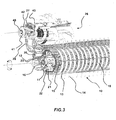
- Figure 2 represents the same pickup device 1, from which the sensing wheels 3, a protective casing 5, feeding baffles 6 and 7 and a protection member 8 have been removed.
- the device according to the present invention comprises a revolving pickup body 10, constituted by a central shaft 11, by side heads 12 integral to said central shaft 11, by at least one transmission wheel 30 and by a plurality of transverse bars 13 bearing teeth 14.
- the transverse bars 13 are parallel to the central shaft 11 and they are housed in specific slots made on the peripheral band of the side heads 12.
- the teeth 14 can be spring-teeth, that is to say they can be connected to the respective transverse bar 13 by means of springs 15 which can be an integral portion of the tooth 14 itself, as in the here-illustrated embodiment.
- the pickup body can further comprise intermediate flanges, that are not shown in the figure, which are connected to the central shaft and are apt to provide an additional support of the transverse bars 13, in the same way as the heads 12.
- the shaft 11 of the pickup body 10 is fastened by means of bearings 16 to a supporting plate 17, which in turn is integral to a side wall 18 of the pickup device 1.
- Bent strips 19 are arranged between the teeth 14 of each transverse bar 13 and are fixed with respect to the pickup device 1. Such bent strips 19 are parallel therebetween and the room between two subsequent strips 19 is covered by the teeth 14.
- Each transverse bar 13 can rotate around its own longitudinal axis thanks to a respective bearing 20.
- Each transverse bar 13 bears a small arm 21 at both ends: an end of said small arm 21 is integral to the transverse bar 13 itself, whereas the other end of the small arm 21 bears a roller 22.
- Said roller 22 is apt to engage a cam-like route (which is not shown) made on the inner surface of the plate 17.
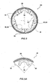
- the transmission wheel 30 is adjacent to the head 12 and it is rigidly joined thereto. As it is shown in figures 5 and 5A , the transmission wheel 30 has the shape of a circular crown and it is divided into sectors 31 that are substantially identical therebetween; the number of such sectors 31 is equal to the number of the transverse bars 13. Each sector 31 has a recess 32 and a projection 33 with complementary shape, so as to allow the mutual interlocking of the sectors 31 to form the transmission wheel 30.
- the intrados of each sector 31 has a recess 34 to house a transverse bar 13 and/or the bearing thereof 20; each sector 31 further has at least two holes 35.
- each sector 31 is fastened to the head 12 by the same mechanical connection members (in this case, bolts 23) which connect the bearings 20 of the transverse bars 13 to the head 12; such bolts 23 pass through the holes 35 of the sectors 31.
- the transmission wheel 30, the bearings 20 and the small arms 21 can be inspected by removing the removable tiles 24 and 25. When the replacement of a bearing 20 is necessary, this can be done by removing the corresponding bolts 23 and by taking out the corresponding sector 31.
- the rotation motion is transmitted by suitable rotation means which, in the present embodiment, comprises a transmission shaft 40 transmitting the motion of the pickup body 10 by means of a driving wheel 27, a transmission chain 28 and a driven transmission wheel 30.
- the rotation motion is further transmitted to the Archimedean screw-like device 26 by means of the driving wheel 41, the chain 42 and the driven wheel 43.
- the driving wheels 27 and 41 are both integral to the transmission shaft 40.
- the teeth 14 pick up the mown material from the ground. Such material is lifted, is made to slide onto the strips 19 and is conveyed to the Archimedean screws 26 and to the chamber for the bale formation in the round baler.
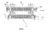
- Figure 6 shows a comparison between an embodiment of a pickup device 101 according to the known art and an embodiment of a pickup device 1 according to the present invention.
- the usable sizes of the pickup bodies indicated with 110 for the known art and with 10 for the present invention, are the same.
- the whole sizes by also considering the sensing wheels 103 for the known art and 3 for the present invention, are different from each other and in particular the pickup device 101 has transversal overall dimensions which are larger than the pickup device 1.
- the motor system 130 of the pickup body 110 is arranged outside the pickup body 110 itself and therefore the thickness of said motor system 130 increases the transversal overall dimensions. Therefore, it should be noted that, when the usable sizes of the pickup body are equal, the device 1 according to the present invention can be realized with transversal overall dimensions which are smaller than the known art.
Landscapes
- Life Sciences & Earth Sciences (AREA)
- Environmental Sciences (AREA)
- Harvesting Machines For Specific Crops (AREA)
- Agricultural Machines (AREA)
- Harvester Elements (AREA)
- Supports For Plants (AREA)
Claims (17)
- Aufnahmevorrichtung (1) für landwirtschaftliche Maschinen, insbesondere Rundballenpressen, die dafür ausgelegt ist, Lagen aus Stroh, Heu, Futterpflanzen und ähnlichen Materialien aufzunehmen, und die aufweist: eine Mittelwelle (11), mindestens zwei Querstege (13), die eine Vielzahl von Zinken (14) tragen, wobei die Querstege (13) dafür ausgelegt sind, mit einem nockenähnlichen Mechanismus zusammenzuwirken, der dafür ausgelegt ist, die Neigung der Vielzahl von Zinken (14) zu variieren, zwei seitliche Köpfe (12), welche mit der Mittelwelle (11) eine Einheit bilden und die mindestens zwei Querstege (13) tragen, die einen Aufnahmekörper (10) bilden, Lager (16, 17), welche die Drehung des Aufnahmekörpers (10) um eine Achse erlauben, die parallel zu den mindestens zwei Querstegen (13) verläuft, mindestens ein Übertragungsrad (30), das eine Einheit mit dem Aufnahmekörper (10) bildet, und ein Drehmittel des mindestens einen Übertragungsrads (30), das dafür ausgelegt ist, die Drehung der Mittelwelle (11) zu verwirklichen,
dadurch gekennzeichnet, dass
das mindestens eine Übertragungsrad (30) direkt an einen der seitlichen Köpfe (13) angrenzt und mittels mechanischer Verbindungselemente (23) an dem Kopf (12) befestigt ist. - Aufnahmevorrichtung (1) nach Anspruch 1, wobei die mindestens zwei Querstreben (13) sich um ihre Längsachse drehen können, die an Lagern (20) befestigt ist.
- Aufnahmevorrichtung (1) nach Anspruch 2, wobei die Enden (20) jeder der mindestens zwei Querstege (13) eine Einheit mit einem kleinen Arm (21) bilden, der eine Walze (22) trägt, die dafür ausgelegt ist, in die nockenartige Route einzugreifen.
- Aufnahmevorrichtung (1) nach einem der vorangehenden Ansprüche, wobei das mindestens eine Übertragungsrad (30) wie eine kreisförmige Krone geformt ist.
- Aufnahmevorrichtung (1) nach einem der vorangehenden Ansprüche, wobei das mindestens eine Übertragungsrad (30) aus zwei oder mehr Sektoren (31) besteht.
- Aufnahmevorrichtung (1) nach Anspruch 5, wobei die Sektoren (31) des mindestens einen Übertragungsrads (30) untereinander im Wesentlichen identisch sind.
- Aufnahmevorrichtung (1) nach Anspruch 5 oder 6, wobei die Sektoren (31) durch Ineinandergreifen aneinander befestigt sind.
- Aufnahmevorrichtung (1) nach einem der Ansprüche 5 bis 7, wobei jeder der Sektoren (31) mittels mechanischer Verbindungselemente (23) am seitlichen Kopf (12) befestigt ist.
- Aufnahmevorrichtung (1) nach einem der vorangehenden Ansprüche, wobei das mindestens eine Übertragungsrad (30) mit Aussparungen (34) für die Unterbringung der mindestens zwei Querstreben (13) und/oder der Lager (20) versehen ist.
- Aufnahmevorrichtung nach Anspruch 9, wenn dieser auf einen der Ansprüche 5 bis 8 bezogen ist, wobei jeder der Sektoren (31) mit mindestens einem dieser Aussparungen (34) versehen ist.
- Aufnahmevorrichtung nach Anspruch 2 oder nach Anspruch 2 und einem der Ansprüche 3 bis 10, wobei die mechanischen Verbindungselemente (23), die das mindestens eine Übertragungsrad (30) und/oder die Sektoren (31) am seitlichen Kopf (12) befestigen, die Gleichen sind, die die Lager (20) der mindestens zwei Querstreben (13) am seitlichen Kopf (12) befestigen.
- Aufnahmevorrichtung (1) nach einem der Ansprüche 1 oder 8 oder 11, wobei die mechanischen Verbindungselemente (23) Bolzen sind.
- Aufnahmevorrichtung (1) nach einem der vorangehenden Ansprüche, wobei die Zinken (14) Federzinken sind.
- Aufnahmeeinrichtung (1) nach einem der vorangehenden Ansprüche, ferner mindestens zwei einstellbare Sensorräder (3) aufweisend.
- Aufnahmevorrichtung (1) nach einem der vorangehenden Ansprüche, ferner eine oder mehrere Einrichtungen (26) nach Art einer Archimedischen Schraube aufweisend.
- Aufnahmevorrichtung (1) nach einem der vorangehenden Ansprüche, wobei das Drehmittel eine Übertragungswelle (40) umfasst, die dafür ausgelegt ist, die Bewegung mittels eines Antriebsrads (27), einer Übertragungskette (28) und des Übertragungsrads (30) auf den Aufnahmekörper (10) zu übertragen.
- Aufnahmepresse, eine Aufnahmevorrichtung (1) nach einem der vorangehenden Ansprüche aufweisend.
Applications Claiming Priority (1)
| Application Number | Priority Date | Filing Date | Title |
|---|---|---|---|
| IT000611A ITRM20060611A1 (it) | 2006-11-10 | 2006-11-10 | Apparecchio raccoglitore a trasmissione interna per macchine agricole in particolare rotoimballatrici |
Publications (2)
| Publication Number | Publication Date |
|---|---|
| EP1920648A1 EP1920648A1 (de) | 2008-05-14 |
| EP1920648B1 true EP1920648B1 (de) | 2010-01-27 |
Family
ID=38982652
Family Applications (1)
| Application Number | Title | Priority Date | Filing Date |
|---|---|---|---|
| EP07119310A Active EP1920648B1 (de) | 2006-11-10 | 2007-10-25 | Aufnehmer für landwirtschaftliche Maschinen, insbesondere für Rundballenpressen |
Country Status (4)
| Country | Link |
|---|---|
| EP (1) | EP1920648B1 (de) |
| AT (1) | ATE456296T1 (de) |
| DE (1) | DE602007004553D1 (de) |
| IT (1) | ITRM20060611A1 (de) |
Cited By (1)
| Publication number | Priority date | Publication date | Assignee | Title |
|---|---|---|---|---|
| CN112021006A (zh) * | 2020-09-28 | 2020-12-04 | 广西丰港农业科技发展有限责任公司 | 一种捡拾齿伸缩式秸秆捡拾打捆机 |
Families Citing this family (3)
| Publication number | Priority date | Publication date | Assignee | Title |
|---|---|---|---|---|
| DE102009017400B4 (de) | 2009-04-15 | 2020-10-29 | Pöttinger Landtechnik Gmbh | Erntemaschine |
| CN102804981A (zh) * | 2012-07-26 | 2012-12-05 | 淮安市苏通市政机械有限公司 | 前置式秸秆打捆机 |
| CN111687556A (zh) * | 2020-05-26 | 2020-09-22 | 江苏沃得高新农业装备有限公司 | 一种打捆机捡拾器滑道的加工方法 |
Family Cites Families (3)
| Publication number | Priority date | Publication date | Assignee | Title |
|---|---|---|---|---|
| US1815327A (en) * | 1927-09-30 | 1931-07-21 | Int Harvester Co | Pick-up attachment for harvester thrashers |
| DE3315033A1 (de) * | 1983-04-26 | 1984-10-31 | Hermann Lohmann Maschinenfabrik Westkirchen, 4722 Ennigerloh | Aufnahmetrommel fuer gemaehtes erntegut |
| ITRM20040466A1 (it) * | 2004-09-29 | 2004-12-29 | Gallignani Spa | Dispositivo alimentatore per macchine agricole per la formatura di balle. |
-
2006
- 2006-11-10 IT IT000611A patent/ITRM20060611A1/it unknown
-
2007
- 2007-10-25 EP EP07119310A patent/EP1920648B1/de active Active
- 2007-10-25 AT AT07119310T patent/ATE456296T1/de not_active IP Right Cessation
- 2007-10-25 DE DE602007004553T patent/DE602007004553D1/de active Active
Cited By (1)
| Publication number | Priority date | Publication date | Assignee | Title |
|---|---|---|---|---|
| CN112021006A (zh) * | 2020-09-28 | 2020-12-04 | 广西丰港农业科技发展有限责任公司 | 一种捡拾齿伸缩式秸秆捡拾打捆机 |
Also Published As
| Publication number | Publication date |
|---|---|
| DE602007004553D1 (de) | 2010-03-18 |
| EP1920648A1 (de) | 2008-05-14 |
| ITRM20060611A1 (it) | 2008-05-11 |
| ATE456296T1 (de) | 2010-02-15 |
Similar Documents
| Publication | Publication Date | Title |
|---|---|---|
| US4525991A (en) | Baler feeder mechanism | |
| EP1920648B1 (de) | Aufnehmer für landwirtschaftliche Maschinen, insbesondere für Rundballenpressen | |
| EP1733609B1 (de) | Pick-up und Rundballenpresse | |
| US4198804A (en) | Round baler machine | |
| CN210298611U (zh) | 一种捆草机械用的无凸轮盘式捡拾器 | |
| EP0201897B1 (de) | Rundballenpresse | |
| JPH0521530B2 (de) | ||
| AU2017250409B2 (en) | Unit for conveying agricultural products | |
| CA2470278A1 (en) | A feeder roller | |
| CA2255144C (en) | Toothbar and toothbar center support arrangement for baler pickup reel | |
| CN104186120A (zh) | 一种草捆捡拾装置 | |
| US6877303B2 (en) | Stub auger support used in pickup | |
| JPH086431Y2 (ja) | コンバインのフィーダ巻付防止装置 | |
| CN201789783U (zh) | 秸秆捡拾输送装置 | |
| KR101083826B1 (ko) | 베일러 | |
| US20150289448A1 (en) | Pick-up assembly and pick-up method with an overload protection | |
| US20060243143A1 (en) | Cylindrical baling press | |
| CN102334408B (zh) | 过桥输送装置及包含其的秸秆收获机 | |
| CA2277517A1 (en) | Round baler belt support roll constructed for deflecting crop material away from roll clearance gaps in baling chamber side walls | |
| CN219698502U (zh) | 一种捡拾器及打捆机 | |
| CN215122261U (zh) | 一种打捆机缠网割网装置 | |
| US7574955B2 (en) | Two position bale forming roll | |
| EP1639882B1 (de) | Vorrichtung für die Reinigung der Walze einer Rundballenpresse | |
| CN120982308A (zh) | 捡拾装置及打捆机 | |
| US4462203A (en) | Sprocket-shaped member for supporting apron tubes in roll baling machine |
Legal Events
| Date | Code | Title | Description |
|---|---|---|---|
| PUAI | Public reference made under article 153(3) epc to a published international application that has entered the european phase |
Free format text: ORIGINAL CODE: 0009012 |
|
| AK | Designated contracting states |
Kind code of ref document: A1 Designated state(s): AT BE BG CH CY CZ DE DK EE ES FI FR GB GR HU IE IS IT LI LT LU LV MC MT NL PL PT RO SE SI SK TR |
|
| AX | Request for extension of the european patent |
Extension state: AL BA HR MK RS |
|
| 17P | Request for examination filed |
Effective date: 20081111 |
|
| AKX | Designation fees paid |
Designated state(s): AT BE BG CH CY CZ DE DK EE ES FI FR GB GR HU IE IS IT LI LT LU LV MC MT NL PL PT RO SE SI SK TR |
|
| GRAP | Despatch of communication of intention to grant a patent |
Free format text: ORIGINAL CODE: EPIDOSNIGR1 |
|
| GRAS | Grant fee paid |
Free format text: ORIGINAL CODE: EPIDOSNIGR3 |
|
| GRAA | (expected) grant |
Free format text: ORIGINAL CODE: 0009210 |
|
| AK | Designated contracting states |
Kind code of ref document: B1 Designated state(s): AT BE BG CH CY CZ DE DK EE ES FI FR GB GR HU IE IS IT LI LT LU LV MC MT NL PL PT RO SE SI SK TR |
|
| REG | Reference to a national code |
Ref country code: GB Ref legal event code: FG4D |
|
| REG | Reference to a national code |
Ref country code: CH Ref legal event code: EP |
|
| REG | Reference to a national code |
Ref country code: IE Ref legal event code: FG4D |
|
| REF | Corresponds to: |
Ref document number: 602007004553 Country of ref document: DE Date of ref document: 20100318 Kind code of ref document: P |
|
| REG | Reference to a national code |
Ref country code: NL Ref legal event code: VDEP Effective date: 20100127 |
|
| LTIE | Lt: invalidation of european patent or patent extension |
Effective date: 20100127 |
|
| PG25 | Lapsed in a contracting state [announced via postgrant information from national office to epo] |
Ref country code: AT Free format text: LAPSE BECAUSE OF FAILURE TO SUBMIT A TRANSLATION OF THE DESCRIPTION OR TO PAY THE FEE WITHIN THE PRESCRIBED TIME-LIMIT Effective date: 20100127 |
|
| PG25 | Lapsed in a contracting state [announced via postgrant information from national office to epo] |
Ref country code: ES Free format text: LAPSE BECAUSE OF FAILURE TO SUBMIT A TRANSLATION OF THE DESCRIPTION OR TO PAY THE FEE WITHIN THE PRESCRIBED TIME-LIMIT Effective date: 20100508 Ref country code: PT Free format text: LAPSE BECAUSE OF FAILURE TO SUBMIT A TRANSLATION OF THE DESCRIPTION OR TO PAY THE FEE WITHIN THE PRESCRIBED TIME-LIMIT Effective date: 20100527 Ref country code: NL Free format text: LAPSE BECAUSE OF FAILURE TO SUBMIT A TRANSLATION OF THE DESCRIPTION OR TO PAY THE FEE WITHIN THE PRESCRIBED TIME-LIMIT Effective date: 20100127 Ref country code: LT Free format text: LAPSE BECAUSE OF FAILURE TO SUBMIT A TRANSLATION OF THE DESCRIPTION OR TO PAY THE FEE WITHIN THE PRESCRIBED TIME-LIMIT Effective date: 20100127 Ref country code: IS Free format text: LAPSE BECAUSE OF FAILURE TO SUBMIT A TRANSLATION OF THE DESCRIPTION OR TO PAY THE FEE WITHIN THE PRESCRIBED TIME-LIMIT Effective date: 20100527 |
|
| PG25 | Lapsed in a contracting state [announced via postgrant information from national office to epo] |
Ref country code: PL Free format text: LAPSE BECAUSE OF FAILURE TO SUBMIT A TRANSLATION OF THE DESCRIPTION OR TO PAY THE FEE WITHIN THE PRESCRIBED TIME-LIMIT Effective date: 20100127 Ref country code: LV Free format text: LAPSE BECAUSE OF FAILURE TO SUBMIT A TRANSLATION OF THE DESCRIPTION OR TO PAY THE FEE WITHIN THE PRESCRIBED TIME-LIMIT Effective date: 20100127 Ref country code: FI Free format text: LAPSE BECAUSE OF FAILURE TO SUBMIT A TRANSLATION OF THE DESCRIPTION OR TO PAY THE FEE WITHIN THE PRESCRIBED TIME-LIMIT Effective date: 20100127 Ref country code: SI Free format text: LAPSE BECAUSE OF FAILURE TO SUBMIT A TRANSLATION OF THE DESCRIPTION OR TO PAY THE FEE WITHIN THE PRESCRIBED TIME-LIMIT Effective date: 20100127 |
|
| PG25 | Lapsed in a contracting state [announced via postgrant information from national office to epo] |
Ref country code: CY Free format text: LAPSE BECAUSE OF FAILURE TO SUBMIT A TRANSLATION OF THE DESCRIPTION OR TO PAY THE FEE WITHIN THE PRESCRIBED TIME-LIMIT Effective date: 20100127 Ref country code: EE Free format text: LAPSE BECAUSE OF FAILURE TO SUBMIT A TRANSLATION OF THE DESCRIPTION OR TO PAY THE FEE WITHIN THE PRESCRIBED TIME-LIMIT Effective date: 20100127 Ref country code: GR Free format text: LAPSE BECAUSE OF FAILURE TO SUBMIT A TRANSLATION OF THE DESCRIPTION OR TO PAY THE FEE WITHIN THE PRESCRIBED TIME-LIMIT Effective date: 20100428 Ref country code: RO Free format text: LAPSE BECAUSE OF FAILURE TO SUBMIT A TRANSLATION OF THE DESCRIPTION OR TO PAY THE FEE WITHIN THE PRESCRIBED TIME-LIMIT Effective date: 20100127 Ref country code: BE Free format text: LAPSE BECAUSE OF FAILURE TO SUBMIT A TRANSLATION OF THE DESCRIPTION OR TO PAY THE FEE WITHIN THE PRESCRIBED TIME-LIMIT Effective date: 20100127 Ref country code: SE Free format text: LAPSE BECAUSE OF FAILURE TO SUBMIT A TRANSLATION OF THE DESCRIPTION OR TO PAY THE FEE WITHIN THE PRESCRIBED TIME-LIMIT Effective date: 20100127 |
|
| PG25 | Lapsed in a contracting state [announced via postgrant information from national office to epo] |
Ref country code: BG Free format text: LAPSE BECAUSE OF FAILURE TO SUBMIT A TRANSLATION OF THE DESCRIPTION OR TO PAY THE FEE WITHIN THE PRESCRIBED TIME-LIMIT Effective date: 20100427 Ref country code: CZ Free format text: LAPSE BECAUSE OF FAILURE TO SUBMIT A TRANSLATION OF THE DESCRIPTION OR TO PAY THE FEE WITHIN THE PRESCRIBED TIME-LIMIT Effective date: 20100127 Ref country code: SK Free format text: LAPSE BECAUSE OF FAILURE TO SUBMIT A TRANSLATION OF THE DESCRIPTION OR TO PAY THE FEE WITHIN THE PRESCRIBED TIME-LIMIT Effective date: 20100127 |
|
| PLBE | No opposition filed within time limit |
Free format text: ORIGINAL CODE: 0009261 |
|
| STAA | Information on the status of an ep patent application or granted ep patent |
Free format text: STATUS: NO OPPOSITION FILED WITHIN TIME LIMIT |
|
| 26N | No opposition filed |
Effective date: 20101028 |
|
| PG25 | Lapsed in a contracting state [announced via postgrant information from national office to epo] |
Ref country code: DK Free format text: LAPSE BECAUSE OF FAILURE TO SUBMIT A TRANSLATION OF THE DESCRIPTION OR TO PAY THE FEE WITHIN THE PRESCRIBED TIME-LIMIT Effective date: 20100127 |
|
| PG25 | Lapsed in a contracting state [announced via postgrant information from national office to epo] |
Ref country code: MC Free format text: LAPSE BECAUSE OF NON-PAYMENT OF DUE FEES Effective date: 20101031 |
|
| PG25 | Lapsed in a contracting state [announced via postgrant information from national office to epo] |
Ref country code: FR Free format text: LAPSE BECAUSE OF NON-PAYMENT OF DUE FEES Effective date: 20101102 |
|
| REG | Reference to a national code |
Ref country code: FR Ref legal event code: ST Effective date: 20110630 |
|
| PG25 | Lapsed in a contracting state [announced via postgrant information from national office to epo] |
Ref country code: IE Free format text: LAPSE BECAUSE OF NON-PAYMENT OF DUE FEES Effective date: 20101025 |
|
| PG25 | Lapsed in a contracting state [announced via postgrant information from national office to epo] |
Ref country code: MT Free format text: LAPSE BECAUSE OF FAILURE TO SUBMIT A TRANSLATION OF THE DESCRIPTION OR TO PAY THE FEE WITHIN THE PRESCRIBED TIME-LIMIT Effective date: 20100127 |
|
| REG | Reference to a national code |
Ref country code: CH Ref legal event code: PL |
|
| GBPC | Gb: european patent ceased through non-payment of renewal fee |
Effective date: 20111025 |
|
| PG25 | Lapsed in a contracting state [announced via postgrant information from national office to epo] |
Ref country code: CH Free format text: LAPSE BECAUSE OF NON-PAYMENT OF DUE FEES Effective date: 20111031 Ref country code: LI Free format text: LAPSE BECAUSE OF NON-PAYMENT OF DUE FEES Effective date: 20111031 |
|
| PG25 | Lapsed in a contracting state [announced via postgrant information from national office to epo] |
Ref country code: GB Free format text: LAPSE BECAUSE OF NON-PAYMENT OF DUE FEES Effective date: 20111025 |
|
| PG25 | Lapsed in a contracting state [announced via postgrant information from national office to epo] |
Ref country code: LU Free format text: LAPSE BECAUSE OF NON-PAYMENT OF DUE FEES Effective date: 20101025 Ref country code: HU Free format text: LAPSE BECAUSE OF FAILURE TO SUBMIT A TRANSLATION OF THE DESCRIPTION OR TO PAY THE FEE WITHIN THE PRESCRIBED TIME-LIMIT Effective date: 20100728 |
|
| PG25 | Lapsed in a contracting state [announced via postgrant information from national office to epo] |
Ref country code: TR Free format text: LAPSE BECAUSE OF FAILURE TO SUBMIT A TRANSLATION OF THE DESCRIPTION OR TO PAY THE FEE WITHIN THE PRESCRIBED TIME-LIMIT Effective date: 20100127 |
|
| P01 | Opt-out of the competence of the unified patent court (upc) registered |
Effective date: 20230525 |
|
| PGFP | Annual fee paid to national office [announced via postgrant information from national office to epo] |
Ref country code: DE Payment date: 20241021 Year of fee payment: 18 |
|
| PGFP | Annual fee paid to national office [announced via postgrant information from national office to epo] |
Ref country code: IT Payment date: 20241025 Year of fee payment: 18 |