EP1920160B1 - Vakuumpumpe - Google Patents
Vakuumpumpe Download PDFInfo
- Publication number
- EP1920160B1 EP1920160B1 EP06792816A EP06792816A EP1920160B1 EP 1920160 B1 EP1920160 B1 EP 1920160B1 EP 06792816 A EP06792816 A EP 06792816A EP 06792816 A EP06792816 A EP 06792816A EP 1920160 B1 EP1920160 B1 EP 1920160B1
- Authority
- EP
- European Patent Office
- Prior art keywords
- pump
- rotor
- vacuum pump
- measuring transducer
- stator
- Prior art date
- Legal status (The legal status is an assumption and is not a legal conclusion. Google has not performed a legal analysis and makes no representation as to the accuracy of the status listed.)
- Not-in-force
Links
- 230000005540 biological transmission Effects 0.000 claims description 14
- 238000005259 measurement Methods 0.000 description 4
- 238000012546 transfer Methods 0.000 description 3
- 230000001133 acceleration Effects 0.000 description 2
- 230000006378 damage Effects 0.000 description 2
- 238000012544 monitoring process Methods 0.000 description 2
- 230000032683 aging Effects 0.000 description 1
- 230000006835 compression Effects 0.000 description 1
- 238000007906 compression Methods 0.000 description 1
- 238000011156 evaluation Methods 0.000 description 1
- 238000013021 overheating Methods 0.000 description 1
Images
Classifications
-
- F—MECHANICAL ENGINEERING; LIGHTING; HEATING; WEAPONS; BLASTING
- F04—POSITIVE - DISPLACEMENT MACHINES FOR LIQUIDS; PUMPS FOR LIQUIDS OR ELASTIC FLUIDS
- F04D—NON-POSITIVE-DISPLACEMENT PUMPS
- F04D19/00—Axial-flow pumps
- F04D19/02—Multi-stage pumps
- F04D19/04—Multi-stage pumps specially adapted to the production of a high vacuum, e.g. molecular pumps
- F04D19/042—Turbomolecular vacuum pumps
-
- F—MECHANICAL ENGINEERING; LIGHTING; HEATING; WEAPONS; BLASTING
- F04—POSITIVE - DISPLACEMENT MACHINES FOR LIQUIDS; PUMPS FOR LIQUIDS OR ELASTIC FLUIDS
- F04D—NON-POSITIVE-DISPLACEMENT PUMPS
- F04D27/00—Control, e.g. regulation, of pumps, pumping installations or pumping systems specially adapted for elastic fluids
- F04D27/001—Testing thereof; Determination or simulation of flow characteristics; Stall or surge detection, e.g. condition monitoring
Definitions
- the invention relates to a vacuum pump with a pump rotor and a pump stator.
- the pump rotor In vacuum pumps, and especially in high speed turbomolecular pumps, the pump rotor can be heated to a great extent by heat of compression, frictional heat, and possibly other influences. Excessively high rotor temperatures increase the risk of crashes, accelerate material fatigue and change other characteristics of the pump rotor. For this Reason, it is necessary to monitor the rotor temperature and record if necessary.
- the rotor temperature is determined either by a relatively expensive pyrometric measurement.
- the rotor temperature can be determined indirectly by measuring the stator temperature and from this conclusions about the rotor temperature are drawn.
- the indirect measurement is not very accurate and is not suitable for monitoring rapid temperature changes of the pump rotor.
- the object of the invention is in contrast to provide a vacuum pump, can be detected inexpensively and accurately in the physical parameters of the pump rotor.
- the pump rotor has an electrical transducer and a transmitting antenna connected to the transducer.
- a receiving antenna is provided on the pump stator which receives measured values of the transducer from the transmitting antenna which transmits measured values of the transducer.
- An expensive pyrometric measurement or inaccurate indirect measurements of physically variable parameters of the pump rotor can therefore be dispensed with. Since the transducer is located directly on the pump stator, the relevant parameter can be determined very accurately.
- the measured value is sent via the transmitting antenna to the receiving antenna in analogue or digital form, which ensures safe, fast, accurate and error-free transmission.
- the transducer is preferably a temperature sensor, but may also be an acceleration or vibration sensor or a strain sensor, or a combination of a plurality of said sensors.
- an energy transmission coil is provided on the pump stator and on the pump rotor, wherein the pump rotor-side coil is connected via a voltage transformer to the transducer, so that wireless electrical energy is transmitted from the pump stator to the pump rotor for electrical power supply to the transducer can.
- the two energy transfer coils form the primary circuit and the secondary circuit of a transformer.
- the two energy transfer coils may also be parts of the drive motor, i. be through a portion of a motor stator-side stator coil and a motor rotor-side rotor coil.
- the transmitting antenna and the receiving antenna can serve as a power transmission coil.
- the transmitting antenna and the receiving antenna may be arranged axially or radially to each other.
- the transmitting and receiving antenna can be arranged in the region of the axial of the pump rotor.
- the transmitting and receiving antenna can also be arranged outside and away from the axial of the pump rotor.
- one of the two antennas is annular. This is necessary when the two antennas are arranged around a rotor shaft. In order to ensure sufficiently long transmission times, in particular at high speeds of more than 10,000 revolutions per minute, as can occur, for example, in turbomolecular pumps, the two antennas overlap over a large part or the entire circumference.
- both antennas are annular, but interrupted, they can each be used simultaneously as a primary and secondary coil for energy transmission.
- a transponder is arranged on the pump rotor, which transmits a measured transducer measured value only on request via the transmitting antenna to the receiving antenna.
- the measured value transmission interval can be adapted to the respective situation by a corresponding stator-side control.
- the number of measured value transfers is kept as low as possible, which in turn keeps the rotor-side demand for electrical energy as small as possible.
- the units concerned with the rotor power supply can be designed as small as possible.
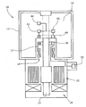
- the figure shows a vacuum pump in a schematic representation.
- the vacuum pump 10 has a pump part, which is essentially formed by a pump stator 12 and a pump rotor 14. Furthermore, the vacuum pump 10 has a drive and bearing part, in which two shaft bearings 16, 18 and a drive motor 20 are arranged.
- a receiving antenna 30 is provided, which is designed to be open and arranged in an annular ring around the rotor shaft 22.
- the stator-side receiving antenna 30 is electrically connected to a control module 32, which the control of the transmitting and receiving operation and the evaluation of the signals received by the receiving antenna 30 is used.
- Rotor side and the receiving antenna 30 axially exactly opposite a corresponding annular transmitting antenna 40 is provided. Furthermore, the pump rotor 14 has a temperature sensor which is connected to a transponder 42, which in turn is connected to the transmitting antenna 40.
- the transducer 44 is a temperature sensor that measures the rotor temperature and sends that value to the transponder 42 continuously or upon request.
- strain sensors, acceleration or vibration sensors or other sensors can be used.
- the receiving antenna 30 is formed as an open circular ring and is used in addition to their antenna characteristics as a secondary coil of a transformer to which the receiving antenna 30 forms the primary coil.
- a corresponding alternating voltage is fed to the receiving antenna 30, which is induced in the transmitting antenna 40.
- the axial distance between the receiving antenna 30 and the transmitting antenna 40 is a few millimeters and possibly even less than 1 mm.
- the transponder 42 in the pump rotor 14 has a transceiver unit, which receives, amplifies and interprets request signals of the control module 32 and forwards measured values of the transducer 44 correspondingly amplified to the transmission antenna 40 upon request.
- a voltage converter 46 is provided which rectifies the AC voltage received, regulates to a constant supply voltage and supplied via supply lines the transducer 44 and the transponder 42 with electrical energy.
- the pump rotor With wireless wireless transmission of measured values provided by pump rotor-side transducers, the pump rotor can be comprehensively, precisely and promptly monitored. This can intervene quickly in case of imminent risk of accident by overheating rotor by a motor control and damage or destruction of the vacuum pump can be avoided. Furthermore, the aging of the pump rotor can be tracked and extrapolated in particular by monitoring and recording of the pump rotor temperature or the life of the vacuum pump can be increased considerably by avoiding high pump rotor temperatures.
Landscapes
- Engineering & Computer Science (AREA)
- Mechanical Engineering (AREA)
- General Engineering & Computer Science (AREA)
- Non-Positive Displacement Air Blowers (AREA)
- Arrangements For Transmission Of Measured Signals (AREA)
- Applications Or Details Of Rotary Compressors (AREA)
Description
- Die Erfindung bezieht sich auf eine Vakuumpumpe mit einem Pumpenrotor und einem Pumpenstator.
- Bei Vakuumpumpen, und insbesondere bei schnelldrehenden Turbomolekularpumpen, kann der Pumpenrotor durch Kompressionswärme, Reibungswärme und gegebenenfalls andere Einflüsse stark erwärmt werden. Durch zu hohe Rotortemperaturen erhöht sich die Crashgefahr, beschleunigt sich die Materialermüdung und ändern sich andere Eigenschaften des Pumpenrotors. Aus diesem Grund ist es erforderlich, die Rotortemperatur zu überwachen und gegebenenfalls aufzuzeichnen.
- Das Dokument
EP 0979947 offenbart die Merkmale des Oberbegriffes von Anspruch 1. - Die Rotortemperatur wird entweder durch eine relativ teure pyrometrische Messung ermittelt. Alternativ kann die Rotortemperatur indirekt ermittelt werden, indem die Statortemperatur gemessen und hieraus Rückschlüsse auf die Rotortemperatur gezogen werden. Die indirekte Messung ist nicht sehr genau und eignet sich nicht für die Überwachung schneller Temperaturänderungen des Pumpenrotors.
- Aufgabe der Erfindung ist es demgegenüber, eine Vakuumpumpe zu schaffen, bei der physikalische Messgrößen des Pumpenrotors preiswert und genau erfasst werden können.
- Diese Aufgabe wird erfindungsgemäß mit den Merkmalen des Patentanspruches 1 gelöst.
- Gemäß der Erfindung weist der Pumpenrotor einen elektrischen Messwandler und eine Sendeantenne auf, die mit dem Messwandler verbunden ist. An dem Pumpenstator ist eine Empfangsantenne vorgesehen, die Messwerte des Messwandlers von der Sendeantenne empfängt, die Messwerte des Messwandlers aussendet. Es wird auf diese Weise eine drahtlose Funkverbindung zur Übertragung von Messwerten zwischen dem Pumpenrotor und dem Pumpenstator geschaffen. Auf eine teure pyrometrische Messung oder ungenaue indirekte Messungen von physikalischen veränderlichen Parametern des Pumpenrotors kann daher verzichtet werden. Da der Messwandler unmittelbar an dem Pumpenstator angeordnet ist, kann der betreffende Parameter sehr genau ermittelt werden. Der Messwert wird über die Sendeantenne an die Empfangsantenne analog oder digital gesendet, wodurch eine sichere, schnelle, genaue und fehlerfreie Übertragung sichergestellt werden kann.
- Der Messwandler ist vorzugsweise ein Temperatursensor, kann jedoch auch ein Beschleunigungs- bzw. Vibrations-Sensor oder ein Dehnungssensor, oder eine Kombination mehrerer der genannten Sensoren sein.
- Gemäß einer bevorzugten Ausgestaltung ist an dem Pumpenstator und an dem Pumpenrotor jeweils eine Energieübertragungs-Spule vorgesehen, wobei die pumpenrotorseitige Spule über einem Spannungswandler mit dem Messwandler verbunden ist, so dass drahtlos elektrische Energie von dem Pumpenstator zu dem Pumpenrotor zur elektrischen Energieversorgung des Messwandlers übertragen werden kann. Die beiden Energieubertragungs-Spulen bilden den Primärkreis und den Sekundärkreis eines Transformators. Durch Einspeisung einer entsprechenden Wechselspannung in die pumpenstatorseitige Energieübertragungs-Spule wird diese auf die pumpenrotorseitige Energieübertragungs-Spule übertragen, so dass in dem Pumpenrotor elektrische Energie zur Versorgung des Messwandlers und gegebenenfalls anderer Aggregate zur Verfügung steht.
- Die beiden Energieubertragungs-Spulen können auch Teile des Antriebsmotors sein, d.h. durch einen Abschnitt einer motorstatorseitigen Statorspule und einer motorrotorseitigen Rotorspule sein. Auch die Sendeantenne und die Empfangsantenne können als Energieübertragungs-Spule dienen.
- Die Sendeantenne und die Empfangsantenne können axial oder radial zueinander angeordnet sein. Die Sende- und Empfangsantenne können im Bereich der Axialen des Pumpenrotors angeordnet sein. Die Sende- und Empfangsantenne können jedoch auch außerhalb und entfernt der Axialen des Pumpenrotors angeordnet sein. Vorzugsweise ist eine der beiden Antennen kreisringförmig ausgebildet. Dies ist dann erforderlich, wenn die beiden Antennen um eine Rotorwelle herum angeordnet sind. Um insbesondere bei hohen Drehzahlen von über 10.000 Umdrehungen pro Minute, wie sie beispielsweise bei Turbomolekularpumpen auftreten können, ausreichend lange Übertragungszeiten sicherzustellen, überdecken sich die beiden Antennen über einen Großteil oder den gesamten Kreisumfang.
- Hierdurch ist eine relativ lange oder gegebenenfalls kontinuierliche Übertragung von Messwerten zwischen der Sendeantenne und der Empfangsantenne möglich. Wenn beide Antennen kreisringförmig, jedoch unterbrochen, ausgebildet sind, können sie jeweils gleichzeitig auch als Primär- und Sekundärspule zur Energieübertragung benutzt werden.
- Gemäß einer bevorzugten Ausgestaltung ist an dem Pumpenrotor ein Transponder angeordnet, der einen Messwandler-Messwert nur auf Anforderung über die Sendeantenne an die Empfangsantenne sendet. Auf diese Weise kann durch eine entsprechende statorseitige Steuerung das Messwertübertragungsintervall an die jeweilige Situation angepasst werden. Hierdurch wird die Anzahl der Messwertübertragungen möglichst gering gehalten, wodurch wiederum der rotorseitige Bedarf an elektrischer Energie möglichst klein gehalten wird. Hierdurch wiederum können die mit der Rotor-Energieversorgung befassten Aggregate kleinstmöglich ausgelegt werden.
- Im Folgenden ist ein Ausführungsbeispiel der Erfindung anhand der Zeichnung näher erläutert.
- Die Figur zeigt eine Vakuumpumpe in schematischer Darstellung.
- In der Figur ist eine als Turbomolekularpumpe ausgebildete Vakuumpumpe 10 dargestellt. Die Vakuumpumpe 10 weist einen Pumpenteil auf, der im wesentlichen von einem Pumpenstator 12 und einem Pumpenrotor 14 gebildet ist. Ferner weist die Vakuumpumpe 10 einen Antriebs- und Lagerungsteil auf, in dem zwei Wellenlager 16, 18 und ein Antriebsmotor 20 angeordnet sind.
- Statorseitig ist eine Empfangsantenne 30 vorgesehen, die offen ausgebildet und kreisringförmig um die Rotorwelle 22 herum angeordnet ist. Die statorseitige Empfangsantenne 30 ist elektrisch mit einem Steuermodul 32 verbunden, das der Steuerung des Sende- und Empfangsbetriebes und der Auswertung der von Empfangsantenne 30 empfangenen Signale dient.
- Rotorseitig und der Empfangsantenne 30 axial genau gegenüberliegend ist eine entsprechende kreisringförmige Sendeantenne 40 vorgesehen. Ferner weist der Pumpenrotor 14 einen Temperatursensor auf, der mit einem Transponder 42 verbunden ist, der seinerseits mit der Sendeantenne 40 verbunden ist.
- Der Messwandler 44 ist ein Temperatursensor, der die Rotortemperatur misst und diesen Wert kontinuierlich oder auf Anforderung an den Transponder 42 sendet. Als Messwandler können alternativ oder ergänzend auch Dehnungssensoren, Beschleunigungs- oder Vibrations-Sensoren oder andere Sensoren verwendet werden.
- Auch die Empfangsantenne 30 ist als offener Kreisring ausgebildet und dient neben ihrer Antenneneigenschaft auch als Sekundärspule eines Transformators, zu dem die Empfangsantenne 30 die Primärspule bildet. Durch die Steuervorrichtung 32 wird eine entsprechende Wechselspannung in die Empfangsantenne 30 eingespeist, die in die Sendeantenne 40 induziert wird. Der axiale Abstand zwischen der Empfangsantenne 30 und der Sendeantenne 40 beträgt wenigen Millimeter und gegebenenfalls sogar weniger als 1 mm.
- Der Transponder 42 in dem Pumpenrotor 14 weist eine Sende-Empfangseinheit auf, die Anforderungssignale des Steuermodules 32 empfängt, verstärkt und interpretiert, sowie Messwerte des Messwandlers 44 auf Anforderung entsprechend verstärkt an die Sendeantenne 40 weiterleitet.
- In dem Pumpenrotor 14 ist ein Spannungswandler 46 vorgesehen, der die empfangene Wechselspannung gleichrichtet, auf eine konstante Versorgungsspannung regelt und über Versorgungsleitungen den Messwandler 44 und den Transponder 42 mit elektrischer Energie versorgt.
- Mit der drahtlosen Funkübertragung von durch pumpenrotorseitige Messwandler zur Verfügung gestellten Messwerte kann der Pumpenrotor umfassend, genau und zeitnah überwacht werden. Hierdurch kann bei drohender Unfallgefahr durch Rotorüberhitzung durch eine Motorsteuerung schnell eingegriffen und eine Beschädigung oder Zerstörung der Vakuumpumpe vermieden werden. Ferner kann insbesondere durch Überwachung und Aufzeichnung der Pumpenrotor-Temperatur die Alterung des Pumpenrotors verfolgt und extrapoliert werden bzw. durch Vermeidung von hohen Pumpenrotor-Temperaturen die Lebensdauer der Vakuumpumpe erheblich erhöht werden.
Claims (6)
- Vakuumpumpe (10) mit einem Pumpenrotor (14) und einem Pumpenstator (12),
dadurch gekennzeichnet,
dass der Pumpenrotor (14) einen elektrischen Messwandler (44) aufweist,
dass an dem Pumpenrotor (14) eine Sendeantenne (40) vorgesehen ist, die mit dem Messwandler (44) verbunden ist, und
dass an dem Pumpenstator (12) eine Empfangsantenne (30) vorgesehen ist, die Messwerte des Messwandlers (44) von der Sendeantenne (40) empfängt. - Vakuumpumpe (10) nach Anspruch 1, dadurch gekennzeichnet, dass an dem Pumpenstator (12) und dem Pumpenrotor (14) jeweils eine Energieübertragungs-Spule vorgesehen ist, wobei die pumpenrotorseitige Spule elektrische Energie für den Messwandler (44) zur Verfügung stellt, so dass drahtlos elektrische Energie von dem Pumpenstator (12) zu dem Pumpenrotor (14) zur elektrischen Versorgung des Messwandlers (44) übertragen werden kann.
- Vakuumpumpe (10) nach Anspruch 1 oder 2, dadurch gekennzeichnet, dass mindestens eine der beiden Antennen (30,40) kreisringförmig ausgebildet ist.
- Vakuumpumpe (10) nach einem der Ansprüche 1 bis 3, dadurch gekennzeichnet, dass an dem Pumpenrotor (14) ein Transponder (42) vorgesehen ist, der mit dem Messwandler (44) und der Sendeantenne (40) verbunden ist und auf Anforderung das Senden eines Messwandler-Messwertes durch die Sendeantenne (40) veranlasst.
- Vakuumpumpe (10) nach einem der Ansprüche 1 bis 4, dadurch gekennzeichnet, dass der Messwandler (44) ein Temperatursensor ist.
- Vakuumpumpe (10) nach einem der Ansprüche 1 bis 5, dadurch gekennzeichnet, dass die Vakuumpumpe (10) eine Turbomolekularpumpe ist.
Applications Claiming Priority (2)
| Application Number | Priority Date | Filing Date | Title |
|---|---|---|---|
| DE102005041500A DE102005041500A1 (de) | 2005-09-01 | 2005-09-01 | Vakuumpumpe |
| PCT/EP2006/065315 WO2007025854A1 (de) | 2005-09-01 | 2006-08-15 | Vakuumpumpe |
Publications (2)
| Publication Number | Publication Date |
|---|---|
| EP1920160A1 EP1920160A1 (de) | 2008-05-14 |
| EP1920160B1 true EP1920160B1 (de) | 2009-01-07 |
Family
ID=37115720
Family Applications (1)
| Application Number | Title | Priority Date | Filing Date |
|---|---|---|---|
| EP06792816A Not-in-force EP1920160B1 (de) | 2005-09-01 | 2006-08-15 | Vakuumpumpe |
Country Status (6)
| Country | Link |
|---|---|
| US (1) | US20100303640A1 (de) |
| EP (1) | EP1920160B1 (de) |
| JP (1) | JP2009507166A (de) |
| CN (1) | CN100585188C (de) |
| DE (2) | DE102005041500A1 (de) |
| WO (1) | WO2007025854A1 (de) |
Families Citing this family (13)
| Publication number | Priority date | Publication date | Assignee | Title |
|---|---|---|---|---|
| DE102007053980A1 (de) * | 2007-11-13 | 2009-05-14 | Pfeiffer Vacuum Gmbh | Vakuumpumpe |
| DE102008019451A1 (de) * | 2008-04-17 | 2009-10-22 | Oerlikon Leybold Vacuum Gmbh | Vakuumpumpe |
| DE102008019472A1 (de) * | 2008-04-17 | 2009-10-22 | Oerlikon Leybold Vacuum Gmbh | Vakuumpumpe |
| KR20130070590A (ko) * | 2010-05-04 | 2013-06-27 | 레미 테크놀러지스 엘엘씨 | 전기 기계 부품 온도 모니터링 |
| FR2964164B1 (fr) * | 2010-09-01 | 2014-05-09 | Snecma | Turbomachine comprenant un element tournant soumis a des conditions extremes |
| US20120075070A1 (en) * | 2010-09-27 | 2012-03-29 | General Electric Company | Real time measurement of rotor surface |
| DE102010049138A1 (de) * | 2010-10-22 | 2012-04-26 | Ksb Aktiengesellschaft | Vorrichtung zur Pumpenüberwachung |
| DE102011112748B3 (de) * | 2011-09-07 | 2012-12-27 | Maschinenfabrik Reinhausen Gmbh | Motorantrieb zur Betätigung eines Stufenschalters |
| US9046431B2 (en) * | 2012-06-28 | 2015-06-02 | Honeywell International Inc. | Single ear stator antenna for wireless torque measurement system |
| CN104005968B (zh) * | 2014-06-05 | 2016-01-20 | 核工业理化工程研究院 | 可测转子表面温度的牵引式分子泵 |
| CN104612984B (zh) * | 2015-01-26 | 2017-02-22 | 核工业理化工程研究院 | 牵引式分子泵的转子端面测温装置 |
| JP2018035684A (ja) * | 2016-08-29 | 2018-03-08 | 株式会社島津製作所 | 真空ポンプ |
| EP3443993A1 (de) * | 2017-08-17 | 2019-02-20 | Berlin Heart GmbH | Pumpe mit einem rotorsensor zur erfassung von physiologischen parametern, strömungs- und bewegungsparametern |
Family Cites Families (21)
| Publication number | Priority date | Publication date | Assignee | Title |
|---|---|---|---|---|
| US3824857A (en) * | 1972-08-07 | 1974-07-23 | Electric Machinery Mfg Co | Temperature measuring system for rotating machines |
| US4723445A (en) * | 1986-05-19 | 1988-02-09 | Neotech Industries, Inc. | Vehicle wheel and tire pressure monitor |
| US5252962A (en) * | 1990-08-03 | 1993-10-12 | Bio Medic Data Systems | System monitoring programmable implantable transponder |
| US5160925C1 (en) * | 1991-04-17 | 2001-03-06 | Halliburton Co | Short hop communication link for downhole mwd system |
| DE4309018A1 (de) * | 1993-03-20 | 1994-09-22 | Balzers Pfeiffer Gmbh | Temperatur-Meßanordnung |
| US5844130A (en) * | 1996-04-03 | 1998-12-01 | Ssi Technologies | Apparatus for maintaining a constant radial distance between a transmitting circuit and an antenna coil |
| JP2000064986A (ja) * | 1998-08-12 | 2000-03-03 | Seiko Seiki Co Ltd | ターボ分子ポンプ |
| DK1135202T3 (da) * | 1998-12-03 | 2003-10-27 | Psi Global Ltd | Kompressor eller vakuumpumpe, som anvender fluid filtre med en skjult maskinlæsbar identifikation |
| DE19857453B4 (de) * | 1998-12-12 | 2008-03-20 | Pfeiffer Vacuum Gmbh | Temperaturüberwachung an Rotoren von Vakuumpumpen |
| US6369712B2 (en) * | 1999-05-17 | 2002-04-09 | The Goodyear Tire & Rubber Company | Response adjustable temperature sensor for transponder |
| DE10018513A1 (de) * | 2000-04-14 | 2001-10-18 | Knorr Bremse Systeme | Überwachungseinrichtung für Bremsscheiben und Überwachungsverfahren zur Überwachung der Temperatur von Bremsscheiben |
| JP3632561B2 (ja) * | 2000-05-12 | 2005-03-23 | 株式会社デンソー | 空気圧検出装置及びタイヤ状態監視システム |
| JP2002039088A (ja) * | 2000-07-26 | 2002-02-06 | Seiko Instruments Inc | 回転体装置 |
| DE10114969A1 (de) * | 2001-03-27 | 2002-10-10 | Leybold Vakuum Gmbh | Turbomolekularpumpe |
| JP2003269367A (ja) * | 2002-03-13 | 2003-09-25 | Boc Edwards Technologies Ltd | 真空ポンプ |
| DE20206267U1 (de) * | 2002-04-20 | 2003-08-28 | Leybold Vakuum Gmbh | Vakuumpumpe |
| US6739840B2 (en) * | 2002-05-22 | 2004-05-25 | Applied Materials Inc | Speed control of variable speed pump |
| JP4082345B2 (ja) * | 2003-12-12 | 2008-04-30 | トヨタ自動車株式会社 | 車輪状態検出装置、車輪及び車体 |
| US20060078435A1 (en) * | 2004-08-19 | 2006-04-13 | Metropolitan Industries | Pump monitoring system |
| US7336153B2 (en) * | 2005-06-30 | 2008-02-26 | Hewlett-Packard Development Company, L.P. | Wireless temperature monitoring for an electronics system |
| EP1949053A2 (de) * | 2005-10-07 | 2008-07-30 | Chemimage Corporation | System und verfahren für einen chemischen abbildungsgefahrenassessor mit einer sonde |
-
2005
- 2005-09-01 DE DE102005041500A patent/DE102005041500A1/de not_active Withdrawn
-
2006
- 2006-08-15 WO PCT/EP2006/065315 patent/WO2007025854A1/de active Application Filing
- 2006-08-15 EP EP06792816A patent/EP1920160B1/de not_active Not-in-force
- 2006-08-15 DE DE502006002609T patent/DE502006002609D1/de active Active
- 2006-08-15 US US11/991,222 patent/US20100303640A1/en not_active Abandoned
- 2006-08-15 CN CN200680031638A patent/CN100585188C/zh not_active Expired - Fee Related
- 2006-08-15 JP JP2008528456A patent/JP2009507166A/ja active Pending
Also Published As
| Publication number | Publication date |
|---|---|
| CN100585188C (zh) | 2010-01-27 |
| WO2007025854A1 (de) | 2007-03-08 |
| DE502006002609D1 (de) | 2009-02-26 |
| CN101253332A (zh) | 2008-08-27 |
| JP2009507166A (ja) | 2009-02-19 |
| DE102005041500A1 (de) | 2007-03-08 |
| EP1920160A1 (de) | 2008-05-14 |
| US20100303640A1 (en) | 2010-12-02 |
Similar Documents
| Publication | Publication Date | Title |
|---|---|---|
| EP1920160B1 (de) | Vakuumpumpe | |
| EP1148266B1 (de) | Überwachungseinrichtung für Bremsscheiben und Verfahren zur Überwachung der Temperatur von Bremsscheiben | |
| EP2046620B1 (de) | Vorrichtung zur überwachung mindestens einer betriebsgrösse eines radsatzlagers | |
| EP3500370B1 (de) | Überwachungs- und steuerungsvorrichtung zur automatisierten optimierung der vermahlungslinie eines walzensystems und entsprechendes verfahren | |
| EP2246680B1 (de) | Elektrowerkzeug mit einer berührungslosen Drehmomentmesseinrichtung und Verfahren zum Messen des Drehmomentes bei einem Elektrowerkzeug | |
| WO2018041704A1 (de) | Wälzkörper zur verwendung in einem wälzlager | |
| WO2010112139A1 (de) | Elektromaschine | |
| EP0901881A2 (de) | Werkzeug oder Werkzeughalter | |
| DE102017223390A1 (de) | Gleitlageranordnung für eine schwere Welle, insbesondere einer Windkraftanlage, sowie Steuersystem und Verfahren zur Betriebssteuerung derselben | |
| EP2113758B1 (de) | Drehmomentsensor mit Telemetriesystem | |
| EP2751823B1 (de) | Stufenschalter mit schneckengetriebe | |
| US9958357B2 (en) | Detecting irregularities in a rotation of roller bodies in a roller bearing | |
| EP2843359A1 (de) | Kupplung mit einem antriebseitigen Kupplungsteil und mit einem abtriebseitigen Kupplungsteil | |
| EP2456594B1 (de) | Elektromechanisches fügemodul mit kraftaufnehmer | |
| EP3158773B1 (de) | Messvorrichtung und verfahren zum telemetrischen übertragen von messdaten von einer messeinheit an einem bewegten system zu einer basisstation | |
| DE202015009412U1 (de) | Werkzeug mit einer Vorrichtung zum Erfassen von Indikatoren für eine vorbeugende Instandhaltung | |
| DE102015216576A1 (de) | Radlageranordnung für eine Fahrzeugachse | |
| EP3728880B1 (de) | Vorrichtung und ein verfahren zur ermittlung einer zustandsgrösse | |
| EP3003611B1 (de) | Werkzeugspannsystem | |
| EP3042097B1 (de) | Bremse mit anordnung zur verschleisserkennung | |
| EP3404810A1 (de) | Verfahren zum überwachen des betriebes einer elektrischen rotierenden maschine | |
| DE19923143A1 (de) | Anordnung zur Online-Überwachung von versagenstoleranten Hochleistungsrotoren | |
| EP2060793B1 (de) | Vakuumpumpe | |
| DE102012015357A1 (de) | Nichtschaltbare Kupplung mit Drehmomentüberwachung | |
| WO2007087783A1 (de) | Vorrichtung zum überwachen von maschinenelementen |
Legal Events
| Date | Code | Title | Description |
|---|---|---|---|
| PUAI | Public reference made under article 153(3) epc to a published international application that has entered the european phase |
Free format text: ORIGINAL CODE: 0009012 |
|
| 17P | Request for examination filed |
Effective date: 20080215 |
|
| AK | Designated contracting states |
Kind code of ref document: A1 Designated state(s): CH DE FR GB IT LI |
|
| GRAP | Despatch of communication of intention to grant a patent |
Free format text: ORIGINAL CODE: EPIDOSNIGR1 |
|
| RBV | Designated contracting states (corrected) |
Designated state(s): CH DE FR GB IT LI |
|
| GRAS | Grant fee paid |
Free format text: ORIGINAL CODE: EPIDOSNIGR3 |
|
| GRAA | (expected) grant |
Free format text: ORIGINAL CODE: 0009210 |
|
| AK | Designated contracting states |
Kind code of ref document: B1 Designated state(s): CH DE FR GB IT LI |
|
| REG | Reference to a national code |
Ref country code: GB Ref legal event code: FG4D Free format text: NOT ENGLISH |
|
| REG | Reference to a national code |
Ref country code: CH Ref legal event code: EP |
|
| REG | Reference to a national code |
Ref country code: CH Ref legal event code: NV Representative=s name: ISLER & PEDRAZZINI AG |
|
| REF | Corresponds to: |
Ref document number: 502006002609 Country of ref document: DE Date of ref document: 20090226 Kind code of ref document: P |
|
| PLBE | No opposition filed within time limit |
Free format text: ORIGINAL CODE: 0009261 |
|
| STAA | Information on the status of an ep patent application or granted ep patent |
Free format text: STATUS: NO OPPOSITION FILED WITHIN TIME LIMIT |
|
| 26N | No opposition filed |
Effective date: 20091008 |
|
| PGFP | Annual fee paid to national office [announced via postgrant information from national office to epo] |
Ref country code: IT Payment date: 20090831 Year of fee payment: 4 |
|
| REG | Reference to a national code |
Ref country code: CH Ref legal event code: PL |
|
| GBPC | Gb: european patent ceased through non-payment of renewal fee |
Effective date: 20100815 |
|
| PG25 | Lapsed in a contracting state [announced via postgrant information from national office to epo] |
Ref country code: CH Free format text: LAPSE BECAUSE OF NON-PAYMENT OF DUE FEES Effective date: 20100831 Ref country code: LI Free format text: LAPSE BECAUSE OF NON-PAYMENT OF DUE FEES Effective date: 20100831 |
|
| REG | Reference to a national code |
Ref country code: FR Ref legal event code: ST Effective date: 20110502 |
|
| PG25 | Lapsed in a contracting state [announced via postgrant information from national office to epo] |
Ref country code: IT Free format text: LAPSE BECAUSE OF NON-PAYMENT OF DUE FEES Effective date: 20100815 |
|
| PG25 | Lapsed in a contracting state [announced via postgrant information from national office to epo] |
Ref country code: FR Free format text: LAPSE BECAUSE OF NON-PAYMENT OF DUE FEES Effective date: 20100831 |
|
| PG25 | Lapsed in a contracting state [announced via postgrant information from national office to epo] |
Ref country code: GB Free format text: LAPSE BECAUSE OF NON-PAYMENT OF DUE FEES Effective date: 20100815 |
|
| PGFP | Annual fee paid to national office [announced via postgrant information from national office to epo] |
Ref country code: FR Payment date: 20090914 Year of fee payment: 4 |
|
| REG | Reference to a national code |
Ref country code: DE Ref legal event code: R082 Ref document number: 502006002609 Country of ref document: DE Representative=s name: DOMPATENT VON KREISLER SELTING WERNER - PARTNE, DE Ref country code: DE Ref legal event code: R081 Ref document number: 502006002609 Country of ref document: DE Owner name: LEYBOLD GMBH, DE Free format text: FORMER OWNER: OERLIKON LEYBOLD VACUUM GMBH, 50968 KOELN, DE |
|
| PGFP | Annual fee paid to national office [announced via postgrant information from national office to epo] |
Ref country code: DE Payment date: 20220803 Year of fee payment: 17 |
|
| P01 | Opt-out of the competence of the unified patent court (upc) registered |
Effective date: 20230421 |
|
| REG | Reference to a national code |
Ref country code: DE Ref legal event code: R119 Ref document number: 502006002609 Country of ref document: DE |