EP1919783B1 - Récipient pour aliments - Google Patents
Récipient pour aliments Download PDFInfo
- Publication number
- EP1919783B1 EP1919783B1 EP06765165A EP06765165A EP1919783B1 EP 1919783 B1 EP1919783 B1 EP 1919783B1 EP 06765165 A EP06765165 A EP 06765165A EP 06765165 A EP06765165 A EP 06765165A EP 1919783 B1 EP1919783 B1 EP 1919783B1
- Authority
- EP
- European Patent Office
- Prior art keywords
- container
- hinge
- hinge part
- blank
- end walls
- Prior art date
- Legal status (The legal status is an assumption and is not a legal conclusion. Google has not performed a legal analysis and makes no representation as to the accuracy of the status listed.)
- Active
Links
- 235000013305 food Nutrition 0.000 title claims abstract description 30
- 238000003860 storage Methods 0.000 claims abstract description 6
- 238000000034 method Methods 0.000 claims description 9
- 238000004026 adhesive bonding Methods 0.000 claims description 5
- 230000015572 biosynthetic process Effects 0.000 claims description 3
- 239000000463 material Substances 0.000 abstract description 5
- 239000011087 paperboard Substances 0.000 abstract description 4
- 239000011111 cardboard Substances 0.000 abstract description 3
- 239000000123 paper Substances 0.000 abstract description 3
- 238000010276 construction Methods 0.000 description 11
- 238000011161 development Methods 0.000 description 3
- 230000018109 developmental process Effects 0.000 description 3
- 230000004048 modification Effects 0.000 description 3
- 238000012986 modification Methods 0.000 description 3
- 238000005304 joining Methods 0.000 description 2
- QNRATNLHPGXHMA-XZHTYLCXSA-N (r)-(6-ethoxyquinolin-4-yl)-[(2s,4s,5r)-5-ethyl-1-azabicyclo[2.2.2]octan-2-yl]methanol;hydrochloride Chemical compound Cl.C([C@H]([C@H](C1)CC)C2)CN1[C@@H]2[C@H](O)C1=CC=NC2=CC=C(OCC)C=C21 QNRATNLHPGXHMA-XZHTYLCXSA-N 0.000 description 1
- 239000011248 coating agent Substances 0.000 description 1
- 238000000576 coating method Methods 0.000 description 1
- 230000003247 decreasing effect Effects 0.000 description 1
- 239000003292 glue Substances 0.000 description 1
- 238000003780 insertion Methods 0.000 description 1
- 230000037431 insertion Effects 0.000 description 1
- 239000007788 liquid Substances 0.000 description 1
- 238000004519 manufacturing process Methods 0.000 description 1
- 235000016709 nutrition Nutrition 0.000 description 1
- 230000002093 peripheral effect Effects 0.000 description 1
- 238000007789 sealing Methods 0.000 description 1
- 238000012163 sequencing technique Methods 0.000 description 1
- 210000002105 tongue Anatomy 0.000 description 1
- 238000003466 welding Methods 0.000 description 1
Images


Classifications
-
- B—PERFORMING OPERATIONS; TRANSPORTING
- B65—CONVEYING; PACKING; STORING; HANDLING THIN OR FILAMENTARY MATERIAL
- B65D—CONTAINERS FOR STORAGE OR TRANSPORT OF ARTICLES OR MATERIALS, e.g. BAGS, BARRELS, BOTTLES, BOXES, CANS, CARTONS, CRATES, DRUMS, JARS, TANKS, HOPPERS, FORWARDING CONTAINERS; ACCESSORIES, CLOSURES, OR FITTINGS THEREFOR; PACKAGING ELEMENTS; PACKAGES
- B65D5/00—Rigid or semi-rigid containers of polygonal cross-section, e.g. boxes, cartons or trays, formed by folding or erecting one or more blanks made of paper
- B65D5/36—Rigid or semi-rigid containers of polygonal cross-section, e.g. boxes, cartons or trays, formed by folding or erecting one or more blanks made of paper specially constructed to allow collapsing and re-erecting without disengagement of side or bottom connections
- B65D5/3607—Rigid or semi-rigid containers of polygonal cross-section, e.g. boxes, cartons or trays, formed by folding or erecting one or more blanks made of paper specially constructed to allow collapsing and re-erecting without disengagement of side or bottom connections formed by folding or erecting a single blank
Definitions
- This invention relates to a container for receiving a food product and in particular the invention is concerned with containers that can be formed by folding a shaped blank of paper, paperboard, cardboard or a similar material.
- a first aspect of the present invention provides a partially assembled container as defined in the appended claim 1.
- This novel container construction provides a partially formed container that has a number of advantages over known constructions such as, for example, those disclosed in GB 2398557 and GB 2321236 .
- it can be moved quickly and easily between a flat configuration to an erect configuration without the need for tabs or tongues to be inserted in pre-cut slots or additional gluing.
- the container "pops up" from the flat configuration to the erect configuration when the sides of the flat container are pulled apart.
- the partially formed container makes very efficient use of the blank material, thereby decreasing costs. Further, the partially formed container can be transported in the flat condition, and then erected easily by the food producer.
- first hinge part is hingedly connected to said one side wall
- second hinge part is rigidly connected to said one end wall.
- the first and second hinge parts lie in substantially the same plane when the container is in a substantially flat condition, and the first hinge part and said one end wall sandwich the second hinge part when the container is in a substantially erect condition.
- the hinge means additionally comprises a third hinge part hingedly connected to the second hinge part and rigidly connected to the said end wall.
- the third hinge part is hingedly connected to the second hinge part and rigidly connected to the said end wall such that the said end wall is sandwiched by the second and third hinge parts.
- the third hinge part is hingedly connected to the second hinge part and rigidly connected to the said end wall such that the said third hinge part is sandwiched by the end wall and the second hinge part.
- the third hinge part is hingedly connected to the second hinge part and rigidly connected to the said end wall, and the first hinge part is securely fastened to one of said triangular side walls when the container is in its substantially erect position provision.
- the provision of the third hinge part complicates the construction of the container slightly, but its provision is advantageous because it improves the integrity of the seal between the second hinge part and the said end wall to improve the shelf life of the food product contained in the finished container.
- the third hinge part and the surface of the end wall to which it is connected may substantially congruent so that the third hinge part of the hinge means and the said end wall provide a basal surface for the container with double thickness.
- This double thickness basal surface helps to prevent or delay leakage for the contents of the food product from the container.
- the hinge means are preferably integral with the said side wall. This feature simplifies the blank from which the partially formed container is constructed, and it helps to improve the integrity of the finished container.
- the partially assembled container according to the first and second preferable alternatives is particularly suited to a relatively automated process where the container is opened by machinery provided for that purpose such that a food product can then be inserted manually or by further machinery, and this development is realised by adopting a two stage construction process in which:
- the partially fastened container described in step (1) is suitable for transportation and storage prior to use.
- the partially fastened container can be folded quickly and easily by apparatus provided for that purpose and then the container can be secured in its erect condition ready for receipt of a food product by fastening the first and second hinge parts as described in step (iii).
- the configuration of the partially formed container allows steps (ii) and (iii) to be accomplished at high production speeds on known forms of folding and fastening apparatus, or apparatus of that type with simple and inexpensive modifications. These benefits are achieved because the partially fastened container lies flat, making it easier for the machinery to pick and denest it.
- the third hinge part is secured to the inner face of the end wall, such that the end wall and the first hinge part sandwich the second and third hinge parts.
- the sandwich pack provides four blank external faces and this simplifies printing onto those external surfaces with advertising, nutritional information or other matter.
- a container to be formed from a blank with very minimal scoring of the joints to provide a good shelf life performance, and also enable the partially assembled container to be made up easily into a flat configuration for transportation and storage and opened equally easily into an erect configuration for insertion of a food product.
- the preferred three part hinge arrangement provides an excellent seal and extended shelf life for the food product, but a two part hinge arrangement would also be possible and might be used where the shelf life of the food product is not a crucial factor.
- the present invention also provides a blank for forming a container for receiving a food product, the blank having triangular side walls and substantially rectangular end walls to enable the formation a generally triangular prism-shaped container with an opening for receiving the food product, the blank further comprising hinge means, the hinge means comprising a first hinge part hingedly connected to a second hinge part and arranged between one of said side walls and one of said end walls to enable a partially assembled container formed from the blank to be moved between a substantially flat position for storage and transportation and a substantially erect position for receiving a food product.
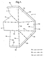
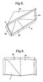
- the container blank or skillet shown in Figure 1 may consist of paper, paperboard, cardboard or a similar material.
- a pair of congruent isosceles-shaped side walls 2a and 2b are alternately arranged with and hingedly connected to generally rectangular end walls 3a and 3b.
- the end walls may be rectangular, but they are preferably trapezoidal so that in the fully assembled container they taper inwardly towards an apex to allow a number of assembled containers to be stacked together.
- the end walls have opposed major and minor edges, designated 4a and 4b respectively. Both of the major edges 4a of the end walls 3a are flanked by the congruent edges of the side walls 2a and 2b. Side wall 3b has one of its major edges 4a integrally formed with a congruent edge of side wall 2b.
- a hinge arrangement integrally formed with side wall 2a has three parts: generally rhombic flap or tab 5; a triangular central part or panel 6; and a three sided part or panel 7. These three parts are integrally formed and connected by fold lines. Panel 7 is integrally formed with side wall 2a.
- the flap 5 is hingedly connected to the minor edge 4a of end wall 3a and this hinge point forms the apex of the finished triangular prism-shaped container.
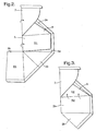
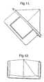
- the hinge arrangement 5,6,7 is folded to overlie the side and end walls 2a, 3a.
- End wall 3b is then brought into abutment with the exposed surfaces of the flap 5 by folding the side wall 2b about its central fold line as shown in Figure 3 .
- the abutting surfaces of the flap 5 and the end wall 3b, both designated as S1 in Figure 2 are glued together to form a permanent join.
- These surfaces S1 are substantially (but not completely) congruent to form a double thickness wall.
- This double thickness wall can be used as the base on the finished container to provide addition resistance against the egress of the food product housed within the container.
- the blank is further folded about the join between the tab 5 and the central panel 6 to bring part of the end wall 3b into abutment with the exposed surface of the central panel 6.
- the abutting surfaces of the first element 6 and the end wall 3b are glued together to form a permanent join and thereby sandwich part of the end wall 3b between the flap 5 and the central panel 6.
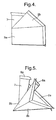
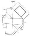
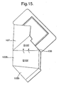
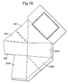
- the resultant partially formed container is shown in Figure 4 , and this configuration represents the partially formed container in its flat configuration.
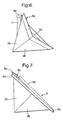
- the configuration of the container means that when it is opened by, say, pulling the side walls 2a and 2b in opposite directions, the container naturally opens out into an erect configuration ready for receiving a food product, such as a sandwich.
- a food product such as a sandwich.
- the movement of the container between the flat configuration shown in Figure 4 and the erect configuration shown in Figure 7 is depicted, as far as it is possible to do so, in Figures 5 and 6 .
- the panel 7 and the end wall 3b sandwich the central panel 6, and the container can be fixed in a fully formed configuration by permanently joining the abutting parts of these panels 6,7.
- part of the panel 7 will abut the part of the end wall 3b and the container can be fixed in a fully formed condition by joining these abutting surfaces.
- a catch or detent mechanism can be provided so that the partially assembled container can be mechanically fastened in an erect condition without the use of glue or other permanent fastening.
- the oral flanges 8a and 8e overlap in the erect configuration and these may also be glued or otherwise fastened together. Alternatively one of these flanges could be omitted from the blank.
- the preferred embodiment of the invention which is depicted in Figures 1 to 9 and described above, has a hinge arrangement made up from three parts.
- a two piece hinge arrangement made up from the panel 7 and the central panel 6 would function in the same manner.
- the use of the flap 5 is advantageous because it improves the integrity of the seal between the hinge arrangement and the end wall 3b, and it also provides a double thickness basal surface in the finished container, but if the shelf life of the food product does not need to be maximised then the flap 5 could be omitted to reduce the amount of material used in the blank.
- lid 10 is provided in place of the oral flap 8d adjacent side wall 2a.
- the lid is used to close the opening 9 in the finished container after the food product has been inserted.
- the lid 10 has an opening 11 which is covered by a transparent film 12 to enable the contents of the assembled container to be viewed after the peripheral end of the lid is sealed to the oral flange 8.
- the blank and container configuration allow the lid to be provided without a fold lines passing through the lid.
- the fold line between the triangular central part or panel (106, 206) and the three sided part or panel (107, 207) in the third and fourth embodiments is a hill fold. This enables the hinge arrangement to be located internally in the erect container, and this modification could be applied to the first and second embodiments.
- the construction of the third and fourth embodiments of the container involve the same steps, but the containers of these developments are particularly suited to a "pick and place" arrangement where the container is stored and shipped in a flat pack form, and then the construction finished at the site of the food producer by opening the container and securing the hinge arrangement.
- This second stage in the construction process of opening the container from a substantially flat condition and securing the hinge parts in secure abutment is well suited to automation.
- the hinge parts can be secured by an appropriate means such as gluing, heat sealing or RF welding.
- a food product such as a sandwich can then be placed in the erected container by hand or by apparatus designed for that purpose, and the opening to the container closed and seal with a lid or suitable covering.
- the hinge parts and the end wall provide a quadruple layer of paperboard, and this can be used as the base of the container to stop or slow down the egress of any moisture or liquid that might be contained in the sandwich. Also the construction of this development allows the hinge parts to lie within the container leaving four blank panels on which marketing information can be placed.
- the hinge parts also lie within the container leaving four blank panels on which marketing information can be placed.
- references to sections of the blank being glued should be understood to encompass any form of fastening including RF welded by application of a suitable coating to the surfaces that are being joined.
Abstract
Claims (18)
- Récipient partiellement assemblé destiné à recevoir un produit alimentaire et formé à partir d'une préforme pliée et partiellement attachée (1), le récipient ayant des parois latérales triangulaires (2a, 2b) et des parois axiales sensiblement rectangulaires (3a, 3b) pour permettre la formation d'un récipient en forme de prisme généralement triangulaire avec une ouverture pour recevoir le produit alimentaire, dans lequel un moyen de charnière comprenant une première partie de charnière (7) raccordée en charnière à une deuxième partie de charnière (6) est disposé entre l'une desdites parois latérales (2a) et l'une desdites parois axiales (3b), caractérisé en ce que le récipient partiellement assemblé est formé en fixant l'une desdites première et deuxième parties de charnière (6, 7) sur ladite paroi latérale (2a) ou ladite paroi axiale (3b) et peut être déplacé entre une position sensiblement plate, à laquelle les première et deuxième parties de charnière (6, 7) se trouvent sensiblement dans le même plan, pour le stockage et le transport et une position sensiblement déployée, à laquelle les première et deuxième parties de charnière (6, 7) sont superposées pour recevoir un produit alimentaire.
- Récipient partiellement assemblé selon la revendication 1, dans lequel la première partie de charnière (7) est raccordée en charnière à ladite paroi latérale (2a), et la deuxième partie de charnière (6) est raccordée rigidement à ladite paroi axiale (3b).
- Récipient partiellement assemblé selon la revendication 2, dans lequel la première partie de charnière (7) et ladite paroi axiale (3b) prennent en sandwich la deuxième partie de charnière (6) lorsque le récipient est dans un état sensiblement déployé.
- Récipient partiellement assemblé selon la revendication 1, 2 ou 3, dans lequel le moyen de charnière comprend en outre une troisième partie de charnière (5) raccordée en charnière à la deuxième partie de charnière (6) et raccordée rigidement à ladite paroi axiale (3b) de sorte que ladite paroi axiale (3b) soit prise en sandwich entre les deuxième et troisième parties de charnière (5, 6).
- Récipient partiellement assemblé selon la revendication 1, 2 ou 3, dans lequel le moyen de charnière comprend en outre une troisième partie de charnière (5) raccordée en charnière à la deuxième partie de charnière (6) et raccordée rigidement à ladite paroi axiale (3b) de sorte que ladite troisième partie de charnière (5) soit prise en sandwich entre ladite paroi axiale (3b) et la deuxième partie de charnière (6).
- Récipient partiellement assemblé selon la revendication 1, dans lequel le moyen de charnière comprend en outre une troisième partie de charnière (5) raccordée en charnière à la deuxième partie de charnière (6) et raccordée rigidement à ladite paroi axiale (3b), et la première paroi de charnière (7) est fermement attachée à l'une desdites parois latérales triangulaires (2a, 2b) lorsque le conteneur est dans sa position sensiblement déployée.
- Récipient partiellement assemblé selon l'une quelconque des revendications 4 à 6, dans lequel la troisième partie de charnière (5) et la surface de la paroi axiale (3b) à laquelle elle est raccordée sont sensiblement congruentes.
- Récipient partiellement assemblé selon l'une quelconque des revendications précédentes, dans lequel le moyen de charnière est solidaire de ladite paroi latérale (2a).
- Récipient partiellement assemblé selon l'une quelconque des revendications précédentes, dans lequel un couvercle formé solidairement (10) est disposé pour recouvrir l'ouverture du récipient lorsqu'il se trouve dans son état déployé.
- Préforme (1) pour former un récipient destiné à recevoir un produit alimentaire, la préforme (1) ayant des parois latérales triangulaires (2a, 2b) et des parois axiales sensiblement rectangulaires (3a, 3b) pour permettre la formation d'un récipient en forme de prisme généralement triangulaire avec une ouverture pour recevoir le produit alimentaire, la préforme (1) comprenant en outre un moyen de charnière, le moyen de charnière comprenant une première partie de charnière (7) raccordée en charnière à une deuxième partie de charnière (6) et agencé entre l'une desdites parois latérales (2a) et l'une desdites parois axiales (3b), caractérisée en ce que la préforme (1) permet à un récipient partiellement assemblé d'être formé en pliant la préforme (1) dans une position sensiblement plate suivant laquelle les première et deuxième parties de charnière (6, 7) se trouvent sensiblement dans le même plan et en fixant l'une desdites première et deuxième parties de charnière (6, 7) à ladite paroi latérale (2a) ou à ladite paroi axiale (3b), et d'être déplacé entre une position sensiblement plate pour le stockage et le transport et une position sensiblement déployée, à laquelle les première et deuxième parties de charnière (6, 7) sont superposées pour recevoir un produit alimentaire.
- Préforme selon la revendication 10, dans laquelle la première partie de charnière (7) est raccordée en charnière à ladite paroi latérale (2a).
- Préforme selon la revendication 10 ou 11, dans laquelle le moyen de charnière comprend en outre une troisième partie de charnière (5) raccordée en charnière à la deuxième partie de charnière (6).
- Préforme selon la revendication 12, dans laquelle la troisième partie de charnière (5) et ladite paroi axiale (3b) sont sensiblement congruentes.
- Préforme selon la revendication 13, dans laquelle le moyen de charnière est solidaire de ladite paroi latérale (2a).
- Préforme selon l'une quelconque des revendications 10 à 14, dans laquelle un couvercle formé solidairement (10) est disposé pour recouvrir l'ouverture du récipient lorsqu'il se trouve dans son état déployé.
- Procédé de formation d'un récipient à partir d'une préforme (1) selon la revendication 10 ou 11, le procédé comprenant les étapes suivantes :1) plier le moyen de charnière pour qu'il soit superposé sur au moins l'une desdites parois latérales (2a) ;2) mettre l'une desdites parois axiales (3b) en aboutement contre l'autre desdites parois axiales (3a) en pliant l'autre desdites parois axiales (2b) autour d'une ligne de pli centrale de celle-ci ;3) plier la préforme autour du raccordement entre l'autre desdites parois axiales (3a) et l'une desdites parois latérales (2a) pour mettre une partie de l'une desdites parois axiales (3b) en aboutement contre la surface exposée de la deuxième partie de charnière (6) ;4) coller les surfaces d'aboutement de ladite deuxième partie de charnière (6) et de l'une desdites parois axiales (3b) l'une sur l'autre pour former une jointure permanente ;5) tirer les parois latérales (3a, 3b) dans des directions opposées de sorte que le récipient s'ouvre naturellement dans un état déployé.
- Procédé de formation d'un récipient à partir d'une préforme (1) selon les revendications 12 à 14, le procédé comprenant les étapes suivantes :1) plier le moyen de charnière pour qu'il soit superposé sur l'une desdites parois latérales (2a) et l'autre desdites parois axiales (3a) ;2) mettre l'une desdites parois axiales (3b) en aboutement contre les surfaces exposées de la troisième partie de charnière (5) en pliant l'autre desdites parois axiales (2b) autour d'une ligne de pli centrale de celle-ci ;3) coller les surfaces d'aboutement de ladite troisième partie de charnière (5) et de l'une desdites parois axiales (3b) l'une sur l'autre pour former une jointure permanente ;4) plier la préforme (1) autour du raccordement entre la troisième partie de charnière (5) et la deuxième partie de charnière (6) pour mettre une partie de l'une desdites parois axiales (3b) en aboutement contre la surface exposée de la deuxième partie de charnière (6) ;5) coller les surfaces d'aboutement de la deuxième partie de charnière (6) et de l'une desdites parois axiales (3b) l'une sur l'autre pour former une jointure permanente et de ce fait prendre en sandwich une partie de l'une desdites parois axiales (3b) entre la troisième partie de charnière (5) et la deuxième partie de charnière (6) ;6) tirer les parois latérales (3a, 3b) dans des directions opposées de sorte que le récipient s'ouvre naturellement dans un état dépoyé.
- Procédé de formation d'un récipient à partir d'une préforme (1) selon les revendications 12 à 14, le procédé comprenant les étapes suivantes :1) attacher la troisième partie de charnière (5) sur la surface intérieure de l'une desdites parois axiales (3b) et plier le récipient partiellement attaché dans une configuration sensiblement plate ;2) stocker le récipient partiellement attaché et le transporter chez un producteur d'aliments ;3) ouvrir le récipient partiellement attaché ;4) déployer le récipient en mettant les première et deuxième parties de charnière (6, 7) en aboutement l'une contre l'autre et en attachant le moyen de charnière dans la configuration d'aboutement prêt pour la réception d'un produit alimentaire.
Applications Claiming Priority (3)
| Application Number | Priority Date | Filing Date | Title |
|---|---|---|---|
| GBGB0515677.3A GB0515677D0 (en) | 2005-07-29 | 2005-07-29 | A container for food |
| GBGB0604490.3A GB0604490D0 (en) | 2005-07-29 | 2006-03-06 | Container for food |
| PCT/GB2006/002850 WO2007012880A1 (fr) | 2005-07-29 | 2006-07-28 | Récipient pour aliments |
Publications (3)
| Publication Number | Publication Date |
|---|---|
| EP1919783A1 EP1919783A1 (fr) | 2008-05-14 |
| EP1919783B1 true EP1919783B1 (fr) | 2011-03-09 |
| EP1919783B2 EP1919783B2 (fr) | 2015-12-02 |
Family
ID=37055974
Family Applications (1)
| Application Number | Title | Priority Date | Filing Date |
|---|---|---|---|
| EP06765165.3A Active EP1919783B2 (fr) | 2005-07-29 | 2006-07-28 | Récipient pour aliments |
Country Status (4)
| Country | Link |
|---|---|
| EP (1) | EP1919783B2 (fr) |
| AU (1) | AU2006273776B2 (fr) |
| CA (1) | CA2617330C (fr) |
| WO (1) | WO2007012880A1 (fr) |
Families Citing this family (9)
| Publication number | Priority date | Publication date | Assignee | Title |
|---|---|---|---|---|
| GB2444113B (en) * | 2006-11-23 | 2011-07-27 | Colpac Ltd | Re-sealable container for food |
| GB2447127B (en) * | 2007-02-28 | 2009-06-17 | St Neots Packaging Ltd | Container for snack food |
| GB0703862D0 (en) * | 2007-02-28 | 2007-04-11 | St Neots Packaging Ltd | Container for snack food |
| GB2457943A (en) * | 2008-02-29 | 2009-09-02 | Colpac Ltd | Film coated blank for forming foodstuff container |
| GB2476795A (en) * | 2010-01-06 | 2011-07-13 | Colpac Ltd | Sealed sandwich container |
| GB201205243D0 (en) | 2012-03-26 | 2012-05-09 | Kraft Foods R & D Inc | Packaging and method of opening |
| GB2511559B (en) | 2013-03-07 | 2018-11-14 | Mondelez Uk R&D Ltd | Improved Packaging and Method of Forming Packaging |
| GB2511560B (en) | 2013-03-07 | 2018-11-14 | Mondelez Uk R&D Ltd | Improved Packaging and Method of Forming Packaging |
| GB2546772A (en) * | 2016-01-28 | 2017-08-02 | Keco Ltd | Blank for a carton, and carton formed therefrom |
Family Cites Families (6)
| Publication number | Priority date | Publication date | Assignee | Title |
|---|---|---|---|---|
| US2349589A (en) † | 1942-03-25 | 1944-05-23 | Armour & Co | Carton |
| US3653576A (en) * | 1969-01-13 | 1972-04-04 | Sikob Ab | Folding container having triangular cross section |
| US5522538A (en) † | 1995-01-09 | 1996-06-04 | Westvaco Corporation | Carton and blank with locking top |
| GB9700704D0 (en) * | 1997-01-15 | 1997-03-05 | Colpac Limited | Packaging |
| DE29903316U1 (de) * | 1999-02-25 | 1999-05-12 | Friedrich Freund Gmbh Kartonag | Pentaedrische Verpackung aus kartonartigem Werkstoff und Zuschnitt dafür |
| GB2398557B (en) * | 2003-02-18 | 2006-04-05 | David Rokov | Folded containers |
-
2006
- 2006-07-28 AU AU2006273776A patent/AU2006273776B2/en active Active
- 2006-07-28 EP EP06765165.3A patent/EP1919783B2/fr active Active
- 2006-07-28 WO PCT/GB2006/002850 patent/WO2007012880A1/fr active Application Filing
- 2006-07-28 CA CA2617330A patent/CA2617330C/fr active Active
Also Published As
| Publication number | Publication date |
|---|---|
| AU2006273776A1 (en) | 2007-02-01 |
| CA2617330C (fr) | 2013-12-17 |
| AU2006273776B2 (en) | 2012-11-22 |
| WO2007012880A1 (fr) | 2007-02-01 |
| EP1919783A1 (fr) | 2008-05-14 |
| EP1919783B2 (fr) | 2015-12-02 |
| CA2617330A1 (fr) | 2007-02-01 |
Similar Documents
| Publication | Publication Date | Title |
|---|---|---|
| US7950569B2 (en) | Container for food | |
| EP1919783B1 (fr) | Récipient pour aliments | |
| US20050051461A1 (en) | Folding carton | |
| CA2455236C (fr) | Recipient d'expedition transformable en un recipient de distribution ou d'affichage multidirections | |
| US8740053B2 (en) | Display ready container assembly | |
| US6499655B1 (en) | Compartmented container | |
| US20070051785A1 (en) | Collapsible rigid container | |
| US4477015A (en) | Two-piece, self-locking container | |
| US6557749B1 (en) | Sheet material container erectable from precursor with auto-forming end closure | |
| US4801080A (en) | Ice cream carton | |
| US4154388A (en) | Box construction | |
| GB2321236A (en) | Cartons | |
| WO2008062181A2 (fr) | Emballage refermable pour aliment | |
| JP2021522119A (ja) | 出荷箱 | |
| NZ506739A (en) | Container collapsible to lay flat condition, with extension of wall being connected to adjacent wall by section having vertical and diagonal fold lines | |
| JPH11321846A (ja) | 簡易組立二重側壁容器 | |
| JP3133668U (ja) | 組立式収納箱 | |
| GB2264697A (en) | Containers | |
| JPH1149139A (ja) | 紙 箱 | |
| JPH08169436A (ja) | ボトムロック式紙箱 | |
| JP4334763B2 (ja) | 追加カバーを備えた顆粒状材料用カートン | |
| JPS6129619Y2 (fr) | ||
| JP2008297006A (ja) | 変形包装箱 | |
| EP1216925B1 (fr) | Conteneur et flan pour former sa base | |
| JPS62501409A (ja) | パッケ−ジ・ブランク |
Legal Events
| Date | Code | Title | Description |
|---|---|---|---|
| PUAI | Public reference made under article 153(3) epc to a published international application that has entered the european phase |
Free format text: ORIGINAL CODE: 0009012 |
|
| 17P | Request for examination filed |
Effective date: 20080228 |
|
| AK | Designated contracting states |
Kind code of ref document: A1 Designated state(s): AT BE BG CH CY CZ DE DK EE ES FI FR GB GR HU IE IS IT LI LT LU LV MC NL PL PT RO SE SI SK TR |
|
| 17Q | First examination report despatched |
Effective date: 20090203 |
|
| GRAP | Despatch of communication of intention to grant a patent |
Free format text: ORIGINAL CODE: EPIDOSNIGR1 |
|
| RIN1 | Information on inventor provided before grant (corrected) |
Inventor name: GOLDMAN, NEIL Inventor name: WRIGHT, PHILIP Inventor name: MILLS, FRANK |
|
| GRAS | Grant fee paid |
Free format text: ORIGINAL CODE: EPIDOSNIGR3 |
|
| GRAA | (expected) grant |
Free format text: ORIGINAL CODE: 0009210 |
|
| AK | Designated contracting states |
Kind code of ref document: B1 Designated state(s): AT BE BG CH CY CZ DE DK EE ES FI FR GB GR HU IE IS IT LI LT LU LV MC NL PL PT RO SE SI SK TR |
|
| REG | Reference to a national code |
Ref country code: GB Ref legal event code: FG4D |
|
| REG | Reference to a national code |
Ref country code: CH Ref legal event code: EP |
|
| REG | Reference to a national code |
Ref country code: IE Ref legal event code: FG4D |
|
| REG | Reference to a national code |
Ref country code: CH Ref legal event code: NV Representative=s name: KIRKER & CIE S.A. |
|
| REF | Corresponds to: |
Ref document number: 602006020592 Country of ref document: DE Date of ref document: 20110421 Kind code of ref document: P |
|
| REG | Reference to a national code |
Ref country code: DE Ref legal event code: R096 Ref document number: 602006020592 Country of ref document: DE Effective date: 20110421 |
|
| REG | Reference to a national code |
Ref country code: NL Ref legal event code: T3 |
|
| PG25 | Lapsed in a contracting state [announced via postgrant information from national office to epo] |
Ref country code: LT Free format text: LAPSE BECAUSE OF FAILURE TO SUBMIT A TRANSLATION OF THE DESCRIPTION OR TO PAY THE FEE WITHIN THE PRESCRIBED TIME-LIMIT Effective date: 20110309 Ref country code: ES Free format text: LAPSE BECAUSE OF FAILURE TO SUBMIT A TRANSLATION OF THE DESCRIPTION OR TO PAY THE FEE WITHIN THE PRESCRIBED TIME-LIMIT Effective date: 20110620 Ref country code: LV Free format text: LAPSE BECAUSE OF FAILURE TO SUBMIT A TRANSLATION OF THE DESCRIPTION OR TO PAY THE FEE WITHIN THE PRESCRIBED TIME-LIMIT Effective date: 20110309 Ref country code: SE Free format text: LAPSE BECAUSE OF FAILURE TO SUBMIT A TRANSLATION OF THE DESCRIPTION OR TO PAY THE FEE WITHIN THE PRESCRIBED TIME-LIMIT Effective date: 20110309 Ref country code: GR Free format text: LAPSE BECAUSE OF FAILURE TO SUBMIT A TRANSLATION OF THE DESCRIPTION OR TO PAY THE FEE WITHIN THE PRESCRIBED TIME-LIMIT Effective date: 20110610 |
|
| LTIE | Lt: invalidation of european patent or patent extension |
Effective date: 20110309 |
|
| PG25 | Lapsed in a contracting state [announced via postgrant information from national office to epo] |
Ref country code: CY Free format text: LAPSE BECAUSE OF FAILURE TO SUBMIT A TRANSLATION OF THE DESCRIPTION OR TO PAY THE FEE WITHIN THE PRESCRIBED TIME-LIMIT Effective date: 20110309 Ref country code: SI Free format text: LAPSE BECAUSE OF FAILURE TO SUBMIT A TRANSLATION OF THE DESCRIPTION OR TO PAY THE FEE WITHIN THE PRESCRIBED TIME-LIMIT Effective date: 20110309 Ref country code: FI Free format text: LAPSE BECAUSE OF FAILURE TO SUBMIT A TRANSLATION OF THE DESCRIPTION OR TO PAY THE FEE WITHIN THE PRESCRIBED TIME-LIMIT Effective date: 20110309 Ref country code: BG Free format text: LAPSE BECAUSE OF FAILURE TO SUBMIT A TRANSLATION OF THE DESCRIPTION OR TO PAY THE FEE WITHIN THE PRESCRIBED TIME-LIMIT Effective date: 20110609 Ref country code: AT Free format text: LAPSE BECAUSE OF FAILURE TO SUBMIT A TRANSLATION OF THE DESCRIPTION OR TO PAY THE FEE WITHIN THE PRESCRIBED TIME-LIMIT Effective date: 20110309 |
|
| PG25 | Lapsed in a contracting state [announced via postgrant information from national office to epo] |
Ref country code: BE Free format text: LAPSE BECAUSE OF FAILURE TO SUBMIT A TRANSLATION OF THE DESCRIPTION OR TO PAY THE FEE WITHIN THE PRESCRIBED TIME-LIMIT Effective date: 20110309 |
|
| PG25 | Lapsed in a contracting state [announced via postgrant information from national office to epo] |
Ref country code: PT Free format text: LAPSE BECAUSE OF FAILURE TO SUBMIT A TRANSLATION OF THE DESCRIPTION OR TO PAY THE FEE WITHIN THE PRESCRIBED TIME-LIMIT Effective date: 20110711 Ref country code: EE Free format text: LAPSE BECAUSE OF FAILURE TO SUBMIT A TRANSLATION OF THE DESCRIPTION OR TO PAY THE FEE WITHIN THE PRESCRIBED TIME-LIMIT Effective date: 20110309 |
|
| PG25 | Lapsed in a contracting state [announced via postgrant information from national office to epo] |
Ref country code: IS Free format text: LAPSE BECAUSE OF FAILURE TO SUBMIT A TRANSLATION OF THE DESCRIPTION OR TO PAY THE FEE WITHIN THE PRESCRIBED TIME-LIMIT Effective date: 20110709 Ref country code: RO Free format text: LAPSE BECAUSE OF FAILURE TO SUBMIT A TRANSLATION OF THE DESCRIPTION OR TO PAY THE FEE WITHIN THE PRESCRIBED TIME-LIMIT Effective date: 20110309 Ref country code: CZ Free format text: LAPSE BECAUSE OF FAILURE TO SUBMIT A TRANSLATION OF THE DESCRIPTION OR TO PAY THE FEE WITHIN THE PRESCRIBED TIME-LIMIT Effective date: 20110309 Ref country code: SK Free format text: LAPSE BECAUSE OF FAILURE TO SUBMIT A TRANSLATION OF THE DESCRIPTION OR TO PAY THE FEE WITHIN THE PRESCRIBED TIME-LIMIT Effective date: 20110309 |
|
| PLBI | Opposition filed |
Free format text: ORIGINAL CODE: 0009260 |
|
| PLAX | Notice of opposition and request to file observation + time limit sent |
Free format text: ORIGINAL CODE: EPIDOSNOBS2 |
|
| 26 | Opposition filed |
Opponent name: PARAGON LABELS LIMITED Effective date: 20111209 Opponent name: ST NEOTS PACKAGING LIMITED Effective date: 20111208 |
|
| PG25 | Lapsed in a contracting state [announced via postgrant information from national office to epo] |
Ref country code: PL Free format text: LAPSE BECAUSE OF FAILURE TO SUBMIT A TRANSLATION OF THE DESCRIPTION OR TO PAY THE FEE WITHIN THE PRESCRIBED TIME-LIMIT Effective date: 20110309 Ref country code: MC Free format text: LAPSE BECAUSE OF NON-PAYMENT OF DUE FEES Effective date: 20110731 |
|
| REG | Reference to a national code |
Ref country code: DE Ref legal event code: R026 Ref document number: 602006020592 Country of ref document: DE Effective date: 20111208 |
|
| PLAF | Information modified related to communication of a notice of opposition and request to file observations + time limit |
Free format text: ORIGINAL CODE: EPIDOSCOBS2 |
|
| PG25 | Lapsed in a contracting state [announced via postgrant information from national office to epo] |
Ref country code: IT Free format text: LAPSE BECAUSE OF FAILURE TO SUBMIT A TRANSLATION OF THE DESCRIPTION OR TO PAY THE FEE WITHIN THE PRESCRIBED TIME-LIMIT Effective date: 20110309 |
|
| PLBB | Reply of patent proprietor to notice(s) of opposition received |
Free format text: ORIGINAL CODE: EPIDOSNOBS3 |
|
| PLAP | Information related to despatch of examination report in opposition + time limit deleted |
Free format text: ORIGINAL CODE: EPIDOSDORE2 |
|
| PLAY | Examination report in opposition despatched + time limit |
Free format text: ORIGINAL CODE: EPIDOSNORE2 |
|
| PG25 | Lapsed in a contracting state [announced via postgrant information from national office to epo] |
Ref country code: LU Free format text: LAPSE BECAUSE OF NON-PAYMENT OF DUE FEES Effective date: 20110728 |
|
| PG25 | Lapsed in a contracting state [announced via postgrant information from national office to epo] |
Ref country code: TR Free format text: LAPSE BECAUSE OF FAILURE TO SUBMIT A TRANSLATION OF THE DESCRIPTION OR TO PAY THE FEE WITHIN THE PRESCRIBED TIME-LIMIT Effective date: 20110309 |
|
| PG25 | Lapsed in a contracting state [announced via postgrant information from national office to epo] |
Ref country code: HU Free format text: LAPSE BECAUSE OF FAILURE TO SUBMIT A TRANSLATION OF THE DESCRIPTION OR TO PAY THE FEE WITHIN THE PRESCRIBED TIME-LIMIT Effective date: 20110309 |
|
| PLAB | Opposition data, opponent's data or that of the opponent's representative modified |
Free format text: ORIGINAL CODE: 0009299OPPO |
|
| PLAB | Opposition data, opponent's data or that of the opponent's representative modified |
Free format text: ORIGINAL CODE: 0009299OPPO |
|
| R26 | Opposition filed (corrected) |
Opponent name: COVERIS FLEXIBLES UK LIMITED Effective date: 20111209 |
|
| R26 | Opposition filed (corrected) |
Opponent name: COVERIS FLEXIBLES (ST NEOTS) UK LIMITED Effective date: 20111208 |
|
| REG | Reference to a national code |
Ref country code: FR Ref legal event code: PLFP Year of fee payment: 10 |
|
| PUAH | Patent maintained in amended form |
Free format text: ORIGINAL CODE: 0009272 |
|
| STAA | Information on the status of an ep patent application or granted ep patent |
Free format text: STATUS: PATENT MAINTAINED AS AMENDED |
|
| 27A | Patent maintained in amended form |
Effective date: 20151202 |
|
| AK | Designated contracting states |
Kind code of ref document: B2 Designated state(s): AT BE BG CH CY CZ DE DK EE ES FI FR GB GR HU IE IS IT LI LT LU LV MC NL PL PT RO SE SI SK TR |
|
| REG | Reference to a national code |
Ref country code: DE Ref legal event code: R102 Ref document number: 602006020592 Country of ref document: DE |
|
| REG | Reference to a national code |
Ref country code: CH Ref legal event code: AELC |
|
| REG | Reference to a national code |
Ref country code: NL Ref legal event code: FP |
|
| REG | Reference to a national code |
Ref country code: FR Ref legal event code: PLFP Year of fee payment: 11 |
|
| REG | Reference to a national code |
Ref country code: FR Ref legal event code: PLFP Year of fee payment: 12 |
|
| REG | Reference to a national code |
Ref country code: FR Ref legal event code: PLFP Year of fee payment: 13 |
|
| PGFP | Annual fee paid to national office [announced via postgrant information from national office to epo] |
Ref country code: NL Payment date: 20230626 Year of fee payment: 18 Ref country code: IE Payment date: 20230623 Year of fee payment: 18 Ref country code: FR Payment date: 20230622 Year of fee payment: 18 |
|
| PGFP | Annual fee paid to national office [announced via postgrant information from national office to epo] |
Ref country code: GB Payment date: 20230615 Year of fee payment: 18 Ref country code: CH Payment date: 20230801 Year of fee payment: 18 |
|
| PGFP | Annual fee paid to national office [announced via postgrant information from national office to epo] |
Ref country code: DE Payment date: 20230613 Year of fee payment: 18 |