EP1919083B1 - Bedienvorrichtung - Google Patents
Bedienvorrichtung Download PDFInfo
- Publication number
- EP1919083B1 EP1919083B1 EP07119498.9A EP07119498A EP1919083B1 EP 1919083 B1 EP1919083 B1 EP 1919083B1 EP 07119498 A EP07119498 A EP 07119498A EP 1919083 B1 EP1919083 B1 EP 1919083B1
- Authority
- EP
- European Patent Office
- Prior art keywords
- sum vector
- permanent magnet
- operating device
- magnitude
- hall sensors
- Prior art date
- Legal status (The legal status is an assumption and is not a legal conclusion. Google has not performed a legal analysis and makes no representation as to the accuracy of the status listed.)
- Active
Links
Images
Classifications
-
- H—ELECTRICITY
- H03—ELECTRONIC CIRCUITRY
- H03K—PULSE TECHNIQUE
- H03K17/00—Electronic switching or gating, i.e. not by contact-making and –breaking
- H03K17/94—Electronic switching or gating, i.e. not by contact-making and –breaking characterised by the way in which the control signals are generated
- H03K17/965—Switches controlled by moving an element forming part of the switch
- H03K17/97—Switches controlled by moving an element forming part of the switch using a magnetic movable element
- H03K17/972—Switches controlled by moving an element forming part of the switch using a magnetic movable element having a plurality of control members, e.g. keyboard
-
- G—PHYSICS
- G06—COMPUTING OR CALCULATING; COUNTING
- G06F—ELECTRIC DIGITAL DATA PROCESSING
- G06F3/00—Input arrangements for transferring data to be processed into a form capable of being handled by the computer; Output arrangements for transferring data from processing unit to output unit, e.g. interface arrangements
- G06F3/01—Input arrangements or combined input and output arrangements for interaction between user and computer
- G06F3/03—Arrangements for converting the position or the displacement of a member into a coded form
- G06F3/033—Pointing devices displaced or positioned by the user, e.g. mice, trackballs, pens or joysticks; Accessories therefor
- G06F3/0362—Pointing devices displaced or positioned by the user, e.g. mice, trackballs, pens or joysticks; Accessories therefor with detection of one-dimensional [1D] translations or rotations of an operating part of the device, e.g. scroll wheels, sliders, knobs, rollers or belts
-
- H—ELECTRICITY
- H03—ELECTRONIC CIRCUITRY
- H03K—PULSE TECHNIQUE
- H03K2217/00—Indexing scheme related to electronic switching or gating, i.e. not by contact-making or -breaking covered by H03K17/00
- H03K2217/94—Indexing scheme related to electronic switching or gating, i.e. not by contact-making or -breaking covered by H03K17/00 characterised by the way in which the control signal is generated
- H03K2217/94057—Rotary switches
- H03K2217/94068—Rotary switches with magnetic detection
-
- H—ELECTRICITY
- H03—ELECTRONIC CIRCUITRY
- H03K—PULSE TECHNIQUE
- H03K2217/00—Indexing scheme related to electronic switching or gating, i.e. not by contact-making or -breaking covered by H03K17/00
- H03K2217/94—Indexing scheme related to electronic switching or gating, i.e. not by contact-making or -breaking covered by H03K17/00 characterised by the way in which the control signal is generated
- H03K2217/965—Switches controlled by moving an element forming part of the switch
- H03K2217/9653—Switches controlled by moving an element forming part of the switch with illumination
Definitions
- the invention relates to an operating device with a rotatable about a rotation axis handle, by means of which an annular permanent magnet assembly is rotatably driven about the axis of rotation having a first plane perpendicular to the axis of rotation, wherein a plurality of Hall sensors are fixed in a second plane parallel to the first plane , by which signals can be generated, which can be fed to an evaluation unit for determining the rotational position of the handle, wherein the at least three Hall sensors are arranged at the same radial distance from the axis of rotation and at an angular distance from one another in the region of the magnetic field of the permanent magnet ring.
- Such an arrangement is in the form of a Zündanlassschalters of the DE 199 38 888 A1 known.
- the prior art also includes an angle sensor with a magnetic disk according to EP 1 493 988 A2 ,
- each permanent magnet ring is formed radially circumferentially with a plurality of magnetic poles that form circle segments.
- Each permanent magnet ring is associated with a Hall sensor, wherein the Hall sensors generate digital signals.
- the object of the invention is therefore to provide an operating device of the type mentioned, which has a simple structure with few components and requires a small space.
- the evaluation unit determines reference vectors from the voltages detected by each Hall sensor and a resulting sum vector from the reference vectors, according to the angular position of which a position signal can be generated.
- the at least three Hall sensors are arranged at an equal angular distance from each other. However, this does not have to be because the angular position of the Hall sensors is taken into account in the calculation of the sum vector.
- the handle is tube-like with a continuous cylinder space formed and in the cylinder chamber a display and / or actuator unit is arranged. This creates an additional usable space in the middle of the operating device.
- This display and / or operating unit can be used for example for functional or search lighting or as a button.
- the assembly work is particularly reduced by the fact that the display and / or operating unit is fixedly mounted on the circuit board.
- the position signal determines the position assumed by the handle.
- the amount of the sum vector can be determined and the permanent magnet ring from a normal position in which the sum of the sum vector is a lower normal sum vector amount, in a distance between the permanent magnet ring and Hall sensors reducing switching position in which the sum of the sum vector is an increased switching sum vector amount movable wherein a switching signal is generated when a certain amount of the sum vector is exceeded, and wherein the determined amount of the sum vector is between the normal sum vector amount and the switching sum vector amount.
- the operating device can thus work as a turn / -Drücksteller.
- For the uniqueness of the switching signal triggering of the specific amount of the sum vector may have a hysteresis.
- the permanent magnet ring In order for the permanent magnet ring to remain securely in its normal position during normal rotary actuation of the handle, the permanent magnet ring can be moved out of its normal position into its switching position counter to a spring force.
- the handle and the permanent magnet ring are preferably firmly connected.
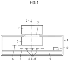
- the illustrated operating device has a handle 1, which is rotatably mounted about a rotation axis 2 and manually rotatable about the rotation axis 2.
- the handle 1 Via a coaxial connector 3, the handle 1 is rotatably connected to a arranged within a housing 4 permanent magnet ring 5, which has a rotation axis 2 to the radially extending first plane 6.
- the Hall sensors 8, 8 ', and 8 "have the same distance from the axis of rotation 2 and the same angular distance from each other.
- the permanent magnet ring 5 has a diametrical magnetization in whose magnetic field the Hall sensors 8, 8 'and 8 "are located.
- Hall voltages are generated in the Hall sensors 8, 8 'and 8 ", which vary according to the respective angular positions of the Hall sensors 8, 8' and 8" to the permanent magnet 5.
- Hall voltages are fed as Hall voltage signals via printed conductors, not shown, of the printed circuit board 9 to a transmitter 10, which is likewise arranged on the printed circuit board 9.
- each Hall sensor 8, 8 'and 8 From the transmitter 10 are from the individual Hall voltage signals each Hall sensor 8, 8 'and 8 "reference vectors 11, 11' and 11" determined and from the reference vectors 11, 11 'and 11 "a sum vector 12 is formed.
- This operating device is an absolute encoder. This means that it can correctly assign the absolute position value directly after switching on.
- Such an operating device may e.g. be used as a turntable for various electrical or electronic devices in which a rotational movement of the handle to be converted into an electrical signal.
- such operating devices are used, for example, in climate control devices for setting the desired internal temperature or an air distribution in the vehicle.
- a use of the operating device is also possible either as Absolutwertgerber or incremental encoder or as a mixture of both.
- it is also conceivable to use it as a steering angle position generator, wheel position transmitter or as a universal human-machine interaction input element (MMI input element).
- the unit of handle 1 and permanent magnet ring 5 is movable from a raised normal position to a lowered switching position. This is done against the force of a compression spring 13 which is supported at one end to the circuit board 9 and applied to the other end of the permanent magnet ring 5.
- a compression spring 13 which is supported at one end to the circuit board 9 and applied to the other end of the permanent magnet ring 5.
- Figure 4 in addition to the normal position of the permanent magnet 5 shown by the solid line and the first plane 6 with a broken line and the bottom of the permanent magnet 5 and its first plane 6 'is shown in the switching position.
- the flux density detected by the Hall sensors 8, 8 'and 8 "increases due to the evaluation electronics 10 and the magnitude of the sum vector due to the signals of the Hall sensors 8, 8' and 8" 12 determined, which increases relative to the normal position in the switching position. If a certain amount of the sum vector 12 is exceeded, the evaluation electronics 10 generates a switching signal.
- the operating device can be used as a turn / push button.
Landscapes
- Engineering & Computer Science (AREA)
- General Engineering & Computer Science (AREA)
- Theoretical Computer Science (AREA)
- Human Computer Interaction (AREA)
- Physics & Mathematics (AREA)
- General Physics & Mathematics (AREA)
- Transmission And Conversion Of Sensor Element Output (AREA)
- Measurement Of Length, Angles, Or The Like Using Electric Or Magnetic Means (AREA)
Description
- Die Erfindung bezieht sich auf eine Bedienvorrichtung mit einer um eine Drehachse drehbaren Handhabe, mittels der eine ringförmige Dauermagnetanordnung um die Drehachse drehbar antreibbar ist, die eine erste zur Drehachse senkrechte Ebene aufweist, wobei mehrere Hallsensoren in einer zur ersten Ebene parallelen zweiten Ebene fest angeordnet sind, durch die Signale erzeugbar sind, die einer Auswerteeinheit zur Ermittlung der Drehposition der Handhabe zuleitbar sind, wobei die wenigstens drei Hallsensoren mit gleichem radialen Abstand zur Drehachse und in einem Winkelabstand zueinander im Bereich des Magnetfeldes des Dauermagnetrings angeordnet sind. Eine derartige Anordnung ist in Form eines Zündanlassschalters aus der
DE 199 38 888 A1 bekannt. Zum Stand der Technik gehört auch ein Winkelsensor mit einer Magnetscheibe gemäßEP 1 493 988 A2 . - Bei einer weiteren Bedienvorrichtung ist es bekannt mindestens zwei Dauermagnetringe zu verwenden, wobei der eine Dauermagnetring den anderen Dauermagnetring umschließt. Jeder Dauermagnetring ist radial umlaufend mit einer Vielzahl Magnetpolen ausgebildet, die Kreissegmente bilden.
- Jedem Dauermagnetring ist ein Hallsensor zugeordnet, wobei die Hallsensoren digitale Signale erzeugen.
- Ein solcher Aufbau ist aufwendig.
- Aufgabe der Erfindung ist es daher eine Bedienvorrichtung der eingangs genannten Art zu schaffen, die einen einfachen Aufbau mit wenigen Bauteilen aufweist und einen geringen Bauraum benötigt.
- Diese Aufgabe wird erfindungsgemäß durch eine Bedienvorrichtung mit den Merkmalen des Anspruchs 1 gelöst.
- Von der Auswerteeinheit werden aus den von jedem Hallsensor erfassten Spannungen Bezugsvektoren und aus den Bezugsvektoren ein resultierender Summenvektor ermittelt, entsprechend dessen Winkelposition ein Positionssignal erzeugbar ist.
- Dabei wird neben der Lösung der Aufgabe weiterhin eine hohe Lebensdauer erreicht, da mechanische Beanspruchungen der Bauteile durch eine galvanische Trennung vermieden werden.
- Vorzugsweise sind die wenigstens drei Hallsensoren in einem gleichen Winkelabstand zueinander angeordnet. Dies muss aber nicht sein, da die Winkelposition der Hallsensoren bei der Berechnung des Summenvektors berücksichtigt wird.
- Eine Vereinfachung der Leitungsverbindungen der Hallsensoren wird dadurch erreicht, dass die Hallsensoren auf einer Leiterplatte angeordnet sind, wobei auf der Leiterplatte auch eine Auswerteelektronik angeordnet sein kann, so dass sich ein kompakter Aufbau ergibt. Erfindungsgemäß ist die Handhabe rohrartig mit einem durchgehenden Zylinderraum ausgebildet und in dem Zylinderraum ist eine Anzeige- und/oder Betätigungseinheit angeordnet. So entsteht ein zusätzlich nutzbarer Platz in der Mitte der Bedienvorrichtung.
- Diese Anzeige- und/oder Betätigungseinheit kann beispielsweise für Funktions- oder Suchbeleuchtung oder als Taster genutzt werden.
- Der Montageaufwand wird besonders dadurch reduziert, dass die Anzeige- und/oder Betätigungseinheit auf der Leiterplatte fest angeordnet ist.
- Das Positionssignal bestimmt dabei die von der Handhabe eingenommene Position.
- Ist von der Auswerteeinheit ein Ausfall eines der Hallsensoren erfassbar und ein dem ausgefallenen Hallsensor zugeordneter fester insbesondere mittlerer Spannungswert zur Ermittlung des resultierenden Summenvektors verwendbar, so wird auf diese Weise eine drastische Verfälschung des Summenvektors vermieden. Das ermittelte Positionssignal ist dann zwar nicht ganz korrekt, würde sich aber sehr stark dem richtigen Wert annähern. Damit kann ein totaler Ausfall des Systems verhindert werden.
- Auch durch Verwendung von einer höheren Anzahl als von drei Hallsensoren wie z. B. von 4, 5, 6 oder mehr Hallsensoren kann durch eine höhere Redundanz die Größe eines Fehlers verringert werden. Die Genauigkeit der berechneten Winkelposition erhöht sich mit der Anzahl der Hallsensoren.
- Von der Auswerteeinheit kann der Betrag des Summenvektors ermittelbar und der Dauermagnetring aus einer Normalposition, in der der Betrag des Summenvektors ein niedrigerer Normalsummenvektorbetrag ist, in eine den Abstand zwischen Dauermagnetring und Hallsensoren verringernde Schaltposition, in der der Betrag des Summenvektors ein erhöhter Schaltsummenvektorbetrag ist, bewegbar sein, wobei bei Überschreitung eines bestimmten Betrages des Summenvektors ein Schaltsignal erzeugbar ist und wobei der bestimmte Betrag des Summenvektors zwischen dem Normalsummenvektorbetrag und dem Schaltsummenvektorbetrag liegt.
- Da der Betrag des Summenvektors auch in hohem Maß gleichmäßig von der magnetischen Flussdichte beeinflusst wird, die bei sich verringerndem Abstand des Dauermagnetrings zu den Hallsensoren zunimmt, ist dies zur Erzeugung des Schaltsignals nutzbar und eine zusätzliche Tastfunktion der Bedienvorrichtung realisierbar. Die Bedienvorrichtung kann somit als Dreh/-Drücksteller arbeiten.
- Zur Eindeutigkeit der Schaltsignalauslösung kann der bestimmte Betrag des Summenvektors eine Hysterese aufweisen.
- Damit bei normaler Drehbetätigung der Handhabe der Dauermagnetring sicher in seiner Normalposition verbleibt, kann der Dauermagnetring entgegen einer Federkraft aus seiner Normalposition in seine Schaltposition bewegbar sein.
- Die Handhabe und der Dauermagnetring sind vorzugsweise fest miteinander verbunden.
- Ein Ausführungsbeispiel der Erfindung ist in der Zeichnung dargestellt und wird im Folgenden näher beschrieben. Es zeigen:
- Figur 1
- eine Prinzipdarstellung eines ersten Ausführungsbeispiels einer Bedienvorrichtung
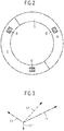
- Figur 2
- eine Draufsicht auf einen Dauermagnetring der Bedienvorrichtung nach
Figur 1 und - Figur 3
- eine Vektordarstellung der von den Hallsensoren der Bedienvorrichtung erfassten Spannungen
- Figur 4
- eine Prinzipdarstellung eines zweiten Ausführungsbeispiels einer Bedienvorrichtung.
- Die dargestellte Bedienvorrichtung weist eine Handhabe 1 auf, die um eine Drehachse 2 drehbar gelagert und manuell um die Drehachse 2 drehbar ist.
- Über ein koaxiales Verbindungsstück 3 ist die Handhabe 1 drehfest mit einem innerhalb eines Gehäuses 4 angeordneten Dauermagnetring 5 verbunden, der eine zur Drehachse 2 sich radial erstreckende erste Ebene 6 aufweist.
- In einem Abstand den Dauermagnetring 5 axial gegenüberliegend sind in einer sich radial zur Drehachse 2 erstreckenden zweiten Ebene 7 drei Hallsensoren 8, 8' und 8" auf einer Leiterplatte 9 fest angeordnet.
- Die Hallsensoren 8, 8', und 8" weisen gleichen Abstand zur Drehachse 2 und gleichen Winkelabstand zueinander auf.
- Der Dauermagnetring 5 besitzt eine diametrale Magnetisierung, in deren Magnetfeld sich die Hallsensoren 8, 8' und 8" befinden.
- Durch das Magnetfeld des Dauermagnetrings 5 werden in den Hallsensoren 8, 8' und 8" sog. Hallspannungen erzeugt, die entsprechend der jeweiligen Winkelpositionen der Hallsensoren 8, 8' und 8" zum Dauermagnet 5 variieren.
- Diese Hallspannungen werden als Hallspannungssignale über nicht dargestellte Leiterbahnen der Leiterplatte 9 einer Auswerteelektronik 10 zugeführt, die ebenfalls auf der Leiterplatte 9 angeordnet ist.
- Von der Auswerteelektronik 10 werden aus den einzelnen Hallspannungssignalen jedes Hallsensors 8, 8' und 8" Bezugsvektoren 11, 11' und 11" ermittelt und aus den Bezugsvektoren 11, 11' und 11" ein Summenvektor 12 gebildet.
- Die Richtung dieses Summenvektors gibt die Winkelposition der Handhabe 1 an.
- Diese Bedienungsvorrichtung ist ein Absolutwertgeber. Dies bedeutet, dass er direkt nach einem Einschalten den absoluten Positionswert richtig zuweisen kann.
- Sollten an allen drei Hallsensoren 8, 8' und 8" Störungen durch z. B. Temperaturdrift, Änderungen am Magnetfeld, Spannungsoffset oder elektromagnetische Störungen auftreten, so ändern sich die Beträge der Bezugsvektoren 11, 11' und 11" proportional. Der Winkel des Summenvektors 12 wird also von den Störungen nicht beeinflusst und ein fester Bezugspunkt wie z. B. die Drehachse 2 ist nicht erforderlich.
- Eine derartige Bedienvorrichtung kann z.B. als Drehsteller für verschiedene elektrische oder elektronische Geräte benutzt werden, bei denen eine Drehbewegung der Handhabe in ein elektrisches Signal umgewandelt werden soll. Im Zusammenhang mit elektrischen Kraftfahrzeugkomponenten werden derartige Bedienvorrichtungen beispielsweise bei Klimabediengeräten zur Einstellung der gewünschten Innentemperatur oder einer Luftverteilung im Fahrzeug eingesetzt. Ein Einsatz der Bedieneinrichtung ist auch wahlweise als Absolutwertgerber oder Inkrementalgeber oder auch als Mischung von beidem möglich. Bei einem Einsatz in einem Kraftfahrzeug ist auch eine Anwendung als Lenkwinkelpositionsgeber, Radpositionsgeber oder als universelles Mensch-Maschine-Interaktions-Eingebeelement (MMI-Eingabeelement) denkbar.
- Das in Figur 4 dargestellte Ausführungsbeispiel der Bedienvorrichtung entspricht weitgehend dem in den
Figuren 1 und2 dargestellten Ausführungsbeispiel, wobei gleiche Teile mit gleichen Bezugszeichen versehen sind. - Im Unterschied zu dem Ausführungsbeispiel der
Figuren 1 und2 ist die Einheit aus Handhabe 1 und Dauermagnetring 5 aus einer angehobenen Normalposition in eine abgesenkte Schaltposition bewegbar. Dies erfolgt entgegen der Kraft einer Druckfeder 13, die mit ihrem einen Ende an der Leiterplatte 9 abgestützt ist und mit ihrem anderen Ende den Dauermagnetring 5 beaufschlagt. In Figur 4 ist neben der mit durchgezogener Linie dargestellten Normalposition des Dauermagneten 5 und dessen erster Ebene 6 mit unterbrochener Linie auch die Unterseite des Dauermagneten 5 und dessen erste Ebene 6' in der Schaltposition dargestellt. - In der Normalposition ist entsprechend dem Ausführungsbeispiel der
Figuren 1 bis 3 die Winkelposition der Handhabe 1 erfassbar. - Erfolgt durch Drücken der Handhabe 1 ein Absenken in die Schaltposition, nimmt die von den Hallsensoren 8, 8' und 8" erfasste Flussdichte zu. Durch die Auswerteelektronik 10 wird aufgrund der Signale der Hallsensoren 8, 8' und 8" auch der Betrag des Summenvektors 12 ermittelt, der sich gegenüber der Normmalposition in der Schaltposition erhöht. Wird dabei ein bestimmter Betrag des Summenvektors 12 überschritten, erzeugt die Auswerteelektronik 10 ein Schaltsignal. Damit ist die Bedienvorrichtung als Dreh-/Drücksteller verwendbar.
Claims (7)
- Bedienvorrichtung mit einer um eine Drehachse (2) drehbaren Handhabe (1), mittels der eine ringförmige Dauermagnetanordnung um die Drehachse (2) drehbar antreibbar ist, die eine erste zur Drehachse (2) senkrechte Ebene (6) aufweist, wobei wenigstens drei Hallsensoren (8, 8', 8") in einer zur ersten Ebene (6) parallelen zweiten Ebene (7) fest angeordnet sind, durch die Signale erzeugbar sind, die einer Auswerteeinheit (10) zur Ermittlung der Drehposition der Handhabe (1) zugeleitet werden, wobei die wenigstens drei Hallsensoren (8, 8', 8") mit gleichem radialen Abstand zur Drehachse (2) und in einem Winkelabstand zueinander im Bereich des Magnetfeldes der ringförmigen Dauermagnetanordnung angeordnet sind, wobei die Dauermagnetanordnung ein diametral magnetisierter Dauermagnetring (5) ist und die Auswerteeinheit (10) ausgebildet ist aus den von jedem Hallsensor (8, 8', 8") erfassten Spannungen Bezugsvektoren (11, 11', 11") und aus den Bezugsvektoren (11, 11', 11") einen resultierenden Summenvektor (12) zu ermitteln, entsprechend dessen Winkelposition ein Positionssignal erzeugbar ist, welches Positionssignal die von der Handhabe (1) eingenommene Position bestimmt, wobei die Handhabe (1) rohrartig mit einem durchgehenden Zylinderraum ausgebildet ist und in dem Zylinderraum eine Anzeige- und/oder Betätigungseinheit angeordnet ist, wobei die Hallsensoren (8, 8', 8") auf einer Leiterplatte (9) angeordnet sind und wobei die Anzeige- und/oder Betätigungseinheit auf der Leiterplatte (9) fest angeordnet ist.
- Bedienvorrichtung nach Anspruch 1, dadurch gekennzeichnet, dass auf der Leiterplatte (9) eine Auswerteelektronik (10) angeordnet ist.
- Bedienvorrichtung nach einem der vorhergehenden Ansprüche, dadurch gekennzeichnet, dass von der Auswerteeinheit (10) ein Ausfall eines der Hallsensoren (8, 8', 8") erfassbar und ein dem ausgefallenen Hallsensor (8, 8', 8") zugeordneter fester insbesondere mittlerer Spannungswert zur Ermittlung des resultierenden Summenvektors (12) verwendbar ist.
- Bedienvorrichtung nach einem der vorhergehenden Ansprüche, dadurch gekennzeichnet, dass von der Auswerteeinheit (10) der Betrag des Summenvektors (12) ermittelbar und der Dauermagnetring (5) aus einer Normalposition, in der der Betrag des Summenvektors (12) ein niedrigerer Normalsummenvektorbetrag ist, in eine den Abstand zwischen Dauermagnetring (5) und Hallsensoren (8, 8', 8") verringernde Schaltposition, in der der Betrag des Summenvektors (12) ein erhöhter Schaltsummenvektorbetrag ist, bewegbar ist, wobei bei Überschreitung eines bestimmten Betrages des Summenvektors (12) ein Schaltsignal erzeugbar ist und wobei der bestimmte Betrag des Summenvektors (12) zwischen dem Normalsummenvektorbetrag und dem Schaltsummenvektorbetrag liegt.
- Bedienvorrichtung nach Anspruch 4, dadurch gekennzeichnet, dass der bestimmte Betrag des Summenvektors (12) eine Hysterese aufweist.
- Bedienvorrichtung nach einem der Ansprüche 4 oder 5, dadurch gekennzeichnet, dass der Dauermagnetring (5) entgegen einer Federkraft aus seiner Normalposition in seine Schaltposition bewegbar ist.
- Bedienvorrichtung nach einem der Ansprüche 4 bis 6, dadurch gekennzeichnet, dass die Handhabe (1) und der Dauermagnetring (5) fest miteinander verbunden sind.
Applications Claiming Priority (2)
| Application Number | Priority Date | Filing Date | Title |
|---|---|---|---|
| DE102006051920 | 2006-10-31 | ||
| DE102007021903A DE102007021903A1 (de) | 2006-10-31 | 2007-05-10 | Bedienvorrichtung |
Publications (3)
| Publication Number | Publication Date |
|---|---|
| EP1919083A2 EP1919083A2 (de) | 2008-05-07 |
| EP1919083A3 EP1919083A3 (de) | 2010-04-14 |
| EP1919083B1 true EP1919083B1 (de) | 2018-06-20 |
Family
ID=39079645
Family Applications (1)
| Application Number | Title | Priority Date | Filing Date |
|---|---|---|---|
| EP07119498.9A Active EP1919083B1 (de) | 2006-10-31 | 2007-10-29 | Bedienvorrichtung |
Country Status (2)
| Country | Link |
|---|---|
| EP (1) | EP1919083B1 (de) |
| DE (1) | DE102007021903A1 (de) |
Cited By (1)
| Publication number | Priority date | Publication date | Assignee | Title |
|---|---|---|---|---|
| DE102021208399A1 (de) | 2021-08-03 | 2023-02-09 | BSH Hausgeräte GmbH | Bedienvorrichtung und Verfahren zum Bereitstellen von wenigstens einem Steuersignal für ein Haushaltsgerät |
Families Citing this family (5)
| Publication number | Priority date | Publication date | Assignee | Title |
|---|---|---|---|---|
| DE102008023651A1 (de) * | 2008-05-15 | 2009-11-19 | Endress + Hauser Conducta Gesellschaft für Mess- und Regeltechnik mbH + Co. KG | Mess-/Schaltgerät mit einer Eingabevorrichtung |
| US20130113465A1 (en) * | 2011-11-04 | 2013-05-09 | Delphi Technologies, Inc. | Multiple function control knob assembly |
| ES2537605B1 (es) * | 2015-03-03 | 2016-01-25 | Seat, S.A. | Dispositivo actuador para unidad de control y procedimiento de control de un dispositivo actuador para unidad de control |
| FR3063382B1 (fr) * | 2017-02-24 | 2019-04-26 | Dav | Dispositif d'indexage de rotor de module de commande |
| DE102017203167B4 (de) * | 2017-02-27 | 2018-10-11 | Audi Ag | Anzeigeeinrichtung |
Citations (1)
| Publication number | Priority date | Publication date | Assignee | Title |
|---|---|---|---|---|
| EP1493988A2 (de) * | 2003-06-30 | 2005-01-05 | Alps Electric Co., Ltd. | Magnetoresistiver Winkelsensor |
Family Cites Families (4)
| Publication number | Priority date | Publication date | Assignee | Title |
|---|---|---|---|---|
| DE19938888C2 (de) * | 1999-08-17 | 2002-01-17 | Siemens Ag | Zündanlaßschalter |
| JP2004226124A (ja) * | 2003-01-20 | 2004-08-12 | Kayaba Ind Co Ltd | 角度センサの回転角度検出装置 |
| DE10349937B4 (de) * | 2003-10-24 | 2016-03-17 | Windhorst Beteiligungsgesellschaft Mbh | Einrichtung zur berührungslosen Erfassung von Schaltstellungen in Kraftfahrzeugschließsystemen |
| DE102004001909A1 (de) * | 2004-01-14 | 2005-08-04 | Daimlerchrysler Ag | Verfahren und Vorrichtung zur Verarbeitung von Sensordaten |
-
2007
- 2007-05-10 DE DE102007021903A patent/DE102007021903A1/de not_active Withdrawn
- 2007-10-29 EP EP07119498.9A patent/EP1919083B1/de active Active
Patent Citations (1)
| Publication number | Priority date | Publication date | Assignee | Title |
|---|---|---|---|---|
| EP1493988A2 (de) * | 2003-06-30 | 2005-01-05 | Alps Electric Co., Ltd. | Magnetoresistiver Winkelsensor |
Cited By (2)
| Publication number | Priority date | Publication date | Assignee | Title |
|---|---|---|---|---|
| DE102021208399A1 (de) | 2021-08-03 | 2023-02-09 | BSH Hausgeräte GmbH | Bedienvorrichtung und Verfahren zum Bereitstellen von wenigstens einem Steuersignal für ein Haushaltsgerät |
| WO2023011838A1 (de) | 2021-08-03 | 2023-02-09 | BSH Hausgeräte GmbH | Bedienvorrichtung und verfahren zum bereitstellen von wenigstens einem steuersignal für ein haushaltsgerät |
Also Published As
| Publication number | Publication date |
|---|---|
| DE102007021903A1 (de) | 2008-05-08 |
| EP1919083A3 (de) | 2010-04-14 |
| EP1919083A2 (de) | 2008-05-07 |
Similar Documents
| Publication | Publication Date | Title |
|---|---|---|
| EP0893668B1 (de) | Winkelsensor | |
| EP2737380B1 (de) | Bedienvorrichtung | |
| EP1238251A1 (de) | Vorrichtung zur messung des winkels und/oder der winkelgeschwindigkeit eines drehbaren körpers und/oder des auf ihn wirkenden drehmoments | |
| WO2007122055A1 (de) | Magnetischer drehwinkelgeber | |
| DE102013218768A1 (de) | Induktive Positionsmesseinrichtung | |
| DE102008023651A1 (de) | Mess-/Schaltgerät mit einer Eingabevorrichtung | |
| DE102008008835A1 (de) | Vorrichtung zum Ermitteln eines Drehmoments | |
| EP2449346A2 (de) | Winkelsensor | |
| EP1919083A2 (de) | Bedienvorrichtung | |
| EP2773923B1 (de) | Winkelsensor auf wirbelstrombasis | |
| EP1979209A1 (de) | Stelleinrichtung, insbesondere für eine kraftfahrzeug-feststellbremse | |
| DE10017061A1 (de) | Anordnung und Verfahren zur Drehwinkelerfassung | |
| EP4163597A1 (de) | Lenksystem für ein kraftfahrzeug | |
| DE102012016287B4 (de) | Verfahren und Wellenlagebestimmungsvorrichtung zum Bestimmen einer Drehposition einer Welle | |
| DE102019124972A1 (de) | Sensoranordnung zur Erfassung eines Lenkmomentes sowie einer absoluten Winkelposition und Sensorvorrichtung mit dieser Sensoranordnung | |
| DE10248060A1 (de) | Magnetfeld-Sensoranordnung für einen Winkelsensor und Verfahren zum Betrieb einer derartigen Sensoranordnung | |
| DE10360042A1 (de) | Verfahren und Meßsystem zur Bestimmung einer absoluten Winkellage | |
| DE19932726C2 (de) | Vorrichtung zum Abfühlen der Relativposition zweier Teile | |
| WO1998027436A1 (de) | Wirbelstrommesswerk | |
| WO2008034890A2 (de) | Vorrichtung zur erfassung einer kraft und/oder eines drehmoments | |
| DE102017222402B4 (de) | Drehwinkelmesseinrichtung | |
| DE102020133576A1 (de) | Lenkanordnung und Fahrzeug sowie Verfahren zum Bestimmen eines Lenkmomentes einer Lenkung | |
| DE10008539C2 (de) | Messvorrichtung zur berührungslosen Erfassung eines Drehwinkels oder eines Drehmoments | |
| DE102013225935A1 (de) | Sensor zum Erfassen einer Winkelstellung eines Messobjektes | |
| WO1999010711A1 (de) | Drehwinkelgeber |
Legal Events
| Date | Code | Title | Description |
|---|---|---|---|
| PUAI | Public reference made under article 153(3) epc to a published international application that has entered the european phase |
Free format text: ORIGINAL CODE: 0009012 |
|
| AK | Designated contracting states |
Kind code of ref document: A2 Designated state(s): AT BE BG CH CY CZ DE DK EE ES FI FR GB GR HU IE IS IT LI LT LU LV MC MT NL PL PT RO SE SI SK TR |
|
| AX | Request for extension of the european patent |
Extension state: AL BA HR MK RS |
|
| RAP1 | Party data changed (applicant data changed or rights of an application transferred) |
Owner name: CONTINENTAL AUTOMOTIVE GMBH |
|
| RIN1 | Information on inventor provided before grant (corrected) |
Inventor name: WERNER, JOSEF Inventor name: BEILKER, DIRK Inventor name: DRAZEK, ALICE |
|
| PUAL | Search report despatched |
Free format text: ORIGINAL CODE: 0009013 |
|
| AK | Designated contracting states |
Kind code of ref document: A3 Designated state(s): AT BE BG CH CY CZ DE DK EE ES FI FR GB GR HU IE IS IT LI LT LU LV MC MT NL PL PT RO SE SI SK TR |
|
| AX | Request for extension of the european patent |
Extension state: AL BA HR MK RS |
|
| 17P | Request for examination filed |
Effective date: 20101014 |
|
| AKX | Designation fees paid |
Designated state(s): AT BE BG CH CY CZ DE DK EE ES FI FR GB GR HU IE IS IT LI LT LU LV MC MT NL PL PT RO SE SI SK TR |
|
| 17Q | First examination report despatched |
Effective date: 20151005 |
|
| GRAP | Despatch of communication of intention to grant a patent |
Free format text: ORIGINAL CODE: EPIDOSNIGR1 |
|
| RIC1 | Information provided on ipc code assigned before grant |
Ipc: H03K 17/972 20060101AFI20171006BHEP Ipc: G06F 3/0362 20130101ALI20171006BHEP |
|
| INTG | Intention to grant announced |
Effective date: 20171107 |
|
| GRAJ | Information related to disapproval of communication of intention to grant by the applicant or resumption of examination proceedings by the epo deleted |
Free format text: ORIGINAL CODE: EPIDOSDIGR1 |
|
| INTC | Intention to grant announced (deleted) | ||
| GRAP | Despatch of communication of intention to grant a patent |
Free format text: ORIGINAL CODE: EPIDOSNIGR1 |
|
| INTG | Intention to grant announced |
Effective date: 20180125 |
|
| GRAS | Grant fee paid |
Free format text: ORIGINAL CODE: EPIDOSNIGR3 |
|
| GRAA | (expected) grant |
Free format text: ORIGINAL CODE: 0009210 |
|
| AK | Designated contracting states |
Kind code of ref document: B1 Designated state(s): AT BE BG CH CY CZ DE DK EE ES FI FR GB GR HU IE IS IT LI LT LU LV MC MT NL PL PT RO SE SI SK TR |
|
| REG | Reference to a national code |
Ref country code: GB Ref legal event code: FG4D Free format text: NOT ENGLISH |
|
| REG | Reference to a national code |
Ref country code: IE Ref legal event code: FG4D Free format text: LANGUAGE OF EP DOCUMENT: GERMAN |
|
| REG | Reference to a national code |
Ref country code: AT Ref legal event code: REF Ref document number: 1011285 Country of ref document: AT Kind code of ref document: T Effective date: 20180715 |
|
| REG | Reference to a national code |
Ref country code: DE Ref legal event code: R096 Ref document number: 502007016238 Country of ref document: DE |
|
| REG | Reference to a national code |
Ref country code: FR Ref legal event code: PLFP Year of fee payment: 12 |
|
| REG | Reference to a national code |
Ref country code: NL Ref legal event code: MP Effective date: 20180620 |
|
| PG25 | Lapsed in a contracting state [announced via postgrant information from national office to epo] |
Ref country code: SE Free format text: LAPSE BECAUSE OF FAILURE TO SUBMIT A TRANSLATION OF THE DESCRIPTION OR TO PAY THE FEE WITHIN THE PRESCRIBED TIME-LIMIT Effective date: 20180620 Ref country code: FI Free format text: LAPSE BECAUSE OF FAILURE TO SUBMIT A TRANSLATION OF THE DESCRIPTION OR TO PAY THE FEE WITHIN THE PRESCRIBED TIME-LIMIT Effective date: 20180620 Ref country code: BG Free format text: LAPSE BECAUSE OF FAILURE TO SUBMIT A TRANSLATION OF THE DESCRIPTION OR TO PAY THE FEE WITHIN THE PRESCRIBED TIME-LIMIT Effective date: 20180920 Ref country code: LT Free format text: LAPSE BECAUSE OF FAILURE TO SUBMIT A TRANSLATION OF THE DESCRIPTION OR TO PAY THE FEE WITHIN THE PRESCRIBED TIME-LIMIT Effective date: 20180620 |
|
| REG | Reference to a national code |
Ref country code: LT Ref legal event code: MG4D |
|
| PG25 | Lapsed in a contracting state [announced via postgrant information from national office to epo] |
Ref country code: GR Free format text: LAPSE BECAUSE OF FAILURE TO SUBMIT A TRANSLATION OF THE DESCRIPTION OR TO PAY THE FEE WITHIN THE PRESCRIBED TIME-LIMIT Effective date: 20180921 Ref country code: LV Free format text: LAPSE BECAUSE OF FAILURE TO SUBMIT A TRANSLATION OF THE DESCRIPTION OR TO PAY THE FEE WITHIN THE PRESCRIBED TIME-LIMIT Effective date: 20180620 |
|
| REG | Reference to a national code |
Ref country code: CH Ref legal event code: PK Free format text: BERICHTIGUNGEN |
|
| PG25 | Lapsed in a contracting state [announced via postgrant information from national office to epo] |
Ref country code: NL Free format text: LAPSE BECAUSE OF FAILURE TO SUBMIT A TRANSLATION OF THE DESCRIPTION OR TO PAY THE FEE WITHIN THE PRESCRIBED TIME-LIMIT Effective date: 20180620 |
|
| RIC2 | Information provided on ipc code assigned after grant |
Ipc: H03K 17/972 20060101AFI20171006BHEP Ipc: G06F 3/0362 20130101ALI20171006BHEP |
|
| PG25 | Lapsed in a contracting state [announced via postgrant information from national office to epo] |
Ref country code: RO Free format text: LAPSE BECAUSE OF FAILURE TO SUBMIT A TRANSLATION OF THE DESCRIPTION OR TO PAY THE FEE WITHIN THE PRESCRIBED TIME-LIMIT Effective date: 20180620 Ref country code: CZ Free format text: LAPSE BECAUSE OF FAILURE TO SUBMIT A TRANSLATION OF THE DESCRIPTION OR TO PAY THE FEE WITHIN THE PRESCRIBED TIME-LIMIT Effective date: 20180620 Ref country code: EE Free format text: LAPSE BECAUSE OF FAILURE TO SUBMIT A TRANSLATION OF THE DESCRIPTION OR TO PAY THE FEE WITHIN THE PRESCRIBED TIME-LIMIT Effective date: 20180620 Ref country code: IS Free format text: LAPSE BECAUSE OF FAILURE TO SUBMIT A TRANSLATION OF THE DESCRIPTION OR TO PAY THE FEE WITHIN THE PRESCRIBED TIME-LIMIT Effective date: 20181020 Ref country code: PL Free format text: LAPSE BECAUSE OF FAILURE TO SUBMIT A TRANSLATION OF THE DESCRIPTION OR TO PAY THE FEE WITHIN THE PRESCRIBED TIME-LIMIT Effective date: 20180620 Ref country code: SK Free format text: LAPSE BECAUSE OF FAILURE TO SUBMIT A TRANSLATION OF THE DESCRIPTION OR TO PAY THE FEE WITHIN THE PRESCRIBED TIME-LIMIT Effective date: 20180620 |
|
| REG | Reference to a national code |
Ref country code: CH Ref legal event code: PK Free format text: BERICHTIGUNGEN |
|
| RIC2 | Information provided on ipc code assigned after grant |
Ipc: H03K 17/972 20060101AFI20171006BHEP Ipc: G06F 3/0362 20130101ALI20171006BHEP |
|
| PG25 | Lapsed in a contracting state [announced via postgrant information from national office to epo] |
Ref country code: ES Free format text: LAPSE BECAUSE OF FAILURE TO SUBMIT A TRANSLATION OF THE DESCRIPTION OR TO PAY THE FEE WITHIN THE PRESCRIBED TIME-LIMIT Effective date: 20180620 Ref country code: IT Free format text: LAPSE BECAUSE OF FAILURE TO SUBMIT A TRANSLATION OF THE DESCRIPTION OR TO PAY THE FEE WITHIN THE PRESCRIBED TIME-LIMIT Effective date: 20180620 |
|
| REG | Reference to a national code |
Ref country code: DE Ref legal event code: R097 Ref document number: 502007016238 Country of ref document: DE |
|
| PLBE | No opposition filed within time limit |
Free format text: ORIGINAL CODE: 0009261 |
|
| STAA | Information on the status of an ep patent application or granted ep patent |
Free format text: STATUS: NO OPPOSITION FILED WITHIN TIME LIMIT |
|
| 26N | No opposition filed |
Effective date: 20190321 |
|
| PG25 | Lapsed in a contracting state [announced via postgrant information from national office to epo] |
Ref country code: DK Free format text: LAPSE BECAUSE OF FAILURE TO SUBMIT A TRANSLATION OF THE DESCRIPTION OR TO PAY THE FEE WITHIN THE PRESCRIBED TIME-LIMIT Effective date: 20180620 |
|
| REG | Reference to a national code |
Ref country code: CH Ref legal event code: PL |
|
| REG | Reference to a national code |
Ref country code: BE Ref legal event code: MM Effective date: 20181031 |
|
| PG25 | Lapsed in a contracting state [announced via postgrant information from national office to epo] |
Ref country code: MC Free format text: LAPSE BECAUSE OF FAILURE TO SUBMIT A TRANSLATION OF THE DESCRIPTION OR TO PAY THE FEE WITHIN THE PRESCRIBED TIME-LIMIT Effective date: 20180620 Ref country code: LU Free format text: LAPSE BECAUSE OF NON-PAYMENT OF DUE FEES Effective date: 20181029 |
|
| REG | Reference to a national code |
Ref country code: IE Ref legal event code: MM4A |
|
| PG25 | Lapsed in a contracting state [announced via postgrant information from national office to epo] |
Ref country code: CH Free format text: LAPSE BECAUSE OF NON-PAYMENT OF DUE FEES Effective date: 20181031 Ref country code: LI Free format text: LAPSE BECAUSE OF NON-PAYMENT OF DUE FEES Effective date: 20181031 Ref country code: BE Free format text: LAPSE BECAUSE OF NON-PAYMENT OF DUE FEES Effective date: 20181031 Ref country code: SI Free format text: LAPSE BECAUSE OF FAILURE TO SUBMIT A TRANSLATION OF THE DESCRIPTION OR TO PAY THE FEE WITHIN THE PRESCRIBED TIME-LIMIT Effective date: 20180620 |
|
| PG25 | Lapsed in a contracting state [announced via postgrant information from national office to epo] |
Ref country code: IE Free format text: LAPSE BECAUSE OF NON-PAYMENT OF DUE FEES Effective date: 20181029 |
|
| REG | Reference to a national code |
Ref country code: AT Ref legal event code: MM01 Ref document number: 1011285 Country of ref document: AT Kind code of ref document: T Effective date: 20181029 |
|
| PG25 | Lapsed in a contracting state [announced via postgrant information from national office to epo] |
Ref country code: AT Free format text: LAPSE BECAUSE OF NON-PAYMENT OF DUE FEES Effective date: 20181029 Ref country code: MT Free format text: LAPSE BECAUSE OF FAILURE TO SUBMIT A TRANSLATION OF THE DESCRIPTION OR TO PAY THE FEE WITHIN THE PRESCRIBED TIME-LIMIT Effective date: 20180620 |
|
| PG25 | Lapsed in a contracting state [announced via postgrant information from national office to epo] |
Ref country code: TR Free format text: LAPSE BECAUSE OF FAILURE TO SUBMIT A TRANSLATION OF THE DESCRIPTION OR TO PAY THE FEE WITHIN THE PRESCRIBED TIME-LIMIT Effective date: 20180620 |
|
| REG | Reference to a national code |
Ref country code: DE Ref legal event code: R084 Ref document number: 502007016238 Country of ref document: DE |
|
| PG25 | Lapsed in a contracting state [announced via postgrant information from national office to epo] |
Ref country code: PT Free format text: LAPSE BECAUSE OF FAILURE TO SUBMIT A TRANSLATION OF THE DESCRIPTION OR TO PAY THE FEE WITHIN THE PRESCRIBED TIME-LIMIT Effective date: 20180620 |
|
| PG25 | Lapsed in a contracting state [announced via postgrant information from national office to epo] |
Ref country code: CY Free format text: LAPSE BECAUSE OF FAILURE TO SUBMIT A TRANSLATION OF THE DESCRIPTION OR TO PAY THE FEE WITHIN THE PRESCRIBED TIME-LIMIT Effective date: 20180620 Ref country code: HU Free format text: LAPSE BECAUSE OF FAILURE TO SUBMIT A TRANSLATION OF THE DESCRIPTION OR TO PAY THE FEE WITHIN THE PRESCRIBED TIME-LIMIT; INVALID AB INITIO Effective date: 20071029 |
|
| REG | Reference to a national code |
Ref country code: DE Ref legal event code: R081 Ref document number: 502007016238 Country of ref document: DE Owner name: CONTINENTAL AUTOMOTIVE TECHNOLOGIES GMBH, DE Free format text: FORMER OWNER: CONTINENTAL AUTOMOTIVE GMBH, 30165 HANNOVER, DE Ref country code: DE Ref legal event code: R081 Ref document number: 502007016238 Country of ref document: DE Owner name: AUMOVIO GERMANY GMBH, DE Free format text: FORMER OWNER: CONTINENTAL AUTOMOTIVE GMBH, 30165 HANNOVER, DE |
|
| REG | Reference to a national code |
Ref country code: GB Ref legal event code: 732E Free format text: REGISTERED BETWEEN 20230223 AND 20230301 |
|
| P01 | Opt-out of the competence of the unified patent court (upc) registered |
Effective date: 20230522 |
|
| REG | Reference to a national code |
Ref country code: DE Ref legal event code: R081 Ref document number: 502007016238 Country of ref document: DE Owner name: CONTINENTAL AUTOMOTIVE TECHNOLOGIES GMBH, DE Free format text: FORMER OWNER: CONTINENTAL AUTOMOTIVE TECHNOLOGIES GMBH, 30165 HANNOVER, DE Ref country code: DE Ref legal event code: R081 Ref document number: 502007016238 Country of ref document: DE Owner name: AUMOVIO GERMANY GMBH, DE Free format text: FORMER OWNER: CONTINENTAL AUTOMOTIVE TECHNOLOGIES GMBH, 30165 HANNOVER, DE |
|
| PGFP | Annual fee paid to national office [announced via postgrant information from national office to epo] |
Ref country code: DE Payment date: 20241031 Year of fee payment: 18 |
|
| PGFP | Annual fee paid to national office [announced via postgrant information from national office to epo] |
Ref country code: GB Payment date: 20241022 Year of fee payment: 18 |
|
| PGFP | Annual fee paid to national office [announced via postgrant information from national office to epo] |
Ref country code: FR Payment date: 20241021 Year of fee payment: 18 |
|
| REG | Reference to a national code |
Ref country code: DE Ref legal event code: R081 Ref document number: 502007016238 Country of ref document: DE Owner name: AUMOVIO GERMANY GMBH, DE Free format text: FORMER OWNER: CONTINENTAL AUTOMOTIVE TECHNOLOGIES GMBH, 30175 HANNOVER, DE |