EP1919003A2 - Method for determining mixture composition of fluorescent materials and method for manufacturing light-emitting device - Google Patents
Method for determining mixture composition of fluorescent materials and method for manufacturing light-emitting device Download PDFInfo
- Publication number
- EP1919003A2 EP1919003A2 EP07021187A EP07021187A EP1919003A2 EP 1919003 A2 EP1919003 A2 EP 1919003A2 EP 07021187 A EP07021187 A EP 07021187A EP 07021187 A EP07021187 A EP 07021187A EP 1919003 A2 EP1919003 A2 EP 1919003A2
- Authority
- EP
- European Patent Office
- Prior art keywords
- light
- function
- fluorescent materials
- mixture composition
- calculating
- Prior art date
- Legal status (The legal status is an assumption and is not a legal conclusion. Google has not performed a legal analysis and makes no representation as to the accuracy of the status listed.)
- Withdrawn
Links
- 239000000203 mixture Substances 0.000 title claims abstract description 76
- 239000000463 material Substances 0.000 title claims abstract description 42
- 238000000034 method Methods 0.000 title claims abstract description 37
- 238000004519 manufacturing process Methods 0.000 title claims description 7
- 238000001228 spectrum Methods 0.000 claims abstract description 19
- 239000003086 colorant Substances 0.000 claims description 25
- 238000009877 rendering Methods 0.000 claims description 14
- 239000004065 semiconductor Substances 0.000 claims description 4
- 239000012780 transparent material Substances 0.000 claims description 4
- 238000010586 diagram Methods 0.000 description 4
- 238000005286 illumination Methods 0.000 description 2
- 229920002050 silicone resin Polymers 0.000 description 1
Images


Classifications
-
- H—ELECTRICITY
- H10—SEMICONDUCTOR DEVICES; ELECTRIC SOLID-STATE DEVICES NOT OTHERWISE PROVIDED FOR
- H10H—INORGANIC LIGHT-EMITTING SEMICONDUCTOR DEVICES HAVING POTENTIAL BARRIERS
- H10H20/00—Individual inorganic light-emitting semiconductor devices having potential barriers, e.g. light-emitting diodes [LED]
- H10H20/80—Constructional details
- H10H20/85—Packages
- H10H20/851—Wavelength conversion means
-
- H—ELECTRICITY
- H10—SEMICONDUCTOR DEVICES; ELECTRIC SOLID-STATE DEVICES NOT OTHERWISE PROVIDED FOR
- H10H—INORGANIC LIGHT-EMITTING SEMICONDUCTOR DEVICES HAVING POTENTIAL BARRIERS
- H10H20/00—Individual inorganic light-emitting semiconductor devices having potential barriers, e.g. light-emitting diodes [LED]
- H10H20/01—Manufacture or treatment
- H10H20/036—Manufacture or treatment of packages
- H10H20/0361—Manufacture or treatment of packages of wavelength conversion means
-
- H—ELECTRICITY
- H10—SEMICONDUCTOR DEVICES; ELECTRIC SOLID-STATE DEVICES NOT OTHERWISE PROVIDED FOR
- H10H—INORGANIC LIGHT-EMITTING SEMICONDUCTOR DEVICES HAVING POTENTIAL BARRIERS
- H10H20/00—Individual inorganic light-emitting semiconductor devices having potential barriers, e.g. light-emitting diodes [LED]
- H10H20/80—Constructional details
- H10H20/85—Packages
- H10H20/851—Wavelength conversion means
- H10H20/8511—Wavelength conversion means characterised by their material, e.g. binder
- H10H20/8512—Wavelength conversion materials
- H10H20/8513—Wavelength conversion materials having two or more wavelength conversion materials
Definitions
- the present invention relates to a method for determining a mixture composition of fluorescent materials and a method for manufacturing a light-emitting device including fluorescent materials.
- a light-emitting device including a light-emitting chip, such as a light-emitting diode, has been developed.
- the Light-emitting chip used in the field of illumination emit blue light or ultraviolet light.
- a light emitter capable of converting the wavelength of light emitted from the light-emitting chip has been developed to achieve light desired by users (objective light).
- Such the light emitter includes a plurality of fluorescent materials being excited by light emitted from the light-emitting chip.
- a method for determining a mixture composition of a plurality of fluorescent materials includes steps of calculating a first function, calculating a second function and determining a secondary mixture composition of the plurality of fluorescent materials.
- the first function is calculated by comparing an objective spectrum of an objective light with a reference spectrum of a reference light.
- the second function is calculated by comparing a primary spectrum of the plurality of fluorescent materials mixed at a primary mixture with the reference spectrum composition.
- the secondary mixture composition is determined on the basis of the result of comparison between the first function and the second function.
- a method for manufacturing a light-emitting device including a light-emitting chip made of a semiconductor material includes steps of determining a secondary mixture composition of a plurality of fluorescent materials, preparing a light emitter, mounting the light-emitting chip on a base and placing the light emitter on or above the light-emitting chip.
- the secondary mixture composition is determined on the basis of a first function and a second function.
- the first function denotes the relative relationship between a reference light and an objective light.
- the second function denotes the relative relationship between the reference light and a light emitted from the plurality of fluorescent materials mixed at a primary mixture composition.
- the light emitter includes the plurality of fluorescent materials mixed on the basis of the secondary mixture composition.
- a light-emitting device 1 obtained by a manufacturing method according to the present embodiment has a light-emitting chip 11 and a light emitter 12.
- the light-emitting chip 11 is a light-emitting diode made of a semiconductor material.
- the light emitter 12 includes a plurality of fluorescent materials being excited by a light emitted from the light-emitting chip 11.
- the light-emitting device 1 further has a transparent material layer 13 in which the light-emitting chip 11 is encapsulated.
- the manufacturing method includes Steps A to C.
- Step A a secondary mixture composition of the fluorescent materials is determined.
- Step B the light emitter 12 is prepared on the basis of the secondary mixture composition.
- the plurality of fluorescence materials is mixed on the basis of the secondary mixture composition.
- the plurality of fluorescence materials mixed on the basis of the secondary mixture composition is putted in a transparent material.
- the transparent material is silicone resin.
- Step C the light-emitting device 1 having the light emitter 12 is manufactured.
- the light-emitting chip 11 is mounted on a base.
- the light emitter 12 is placed on or above the light-emitting chip 11.
- Step A the secondary mixture composition of the fluorescent materials is determined on the basis of a first function and a second function.
- the first function is determined on the basis of the relationship between a reference light and an objective light.
- the second function is determined on the basis of the relationship between the reference light and a light emitted from the fluorescent materials mixed at a primary mixture composition.
- reference light functions as a reference with respect to the objective light and the light emitted from the fluorescent materials.
- objective light is a design target light. In other words, the objective light corresponds to light desired by a user.
- Step A illustrated in Fig. 4 includes the following Steps A1 to A4:
- the first function denotes the relationship between the reference light and the objective light.
- the first function is expressed as a function based on a plurality of test colors and calculated values of light intensities.
- the first function is obtained by the following Steps 11 to 13.
- a first plurality of light intensities Sr(T) is calculated.
- the first plurality of light intensities Sr(T) corresponds to a plurality of test colors T1 to Tn (2 ⁇ n), in the reference light.
- the first plurality of light intensities Sr(T) comprises Sr(T1), Sr(T2), ..., Sr(Tn-1) and Sr(Tn).
- the first plurality of light intensities Sr(T) is calculated by a method of specifying color rendering properties.
- a second plurality of light intensities Sb(T) is calculated.
- the second plurality of light intensities corresponds to the test colors T1 to Tn (2 ⁇ n), in the objective light.
- the second plurality of light intensities Sb(T) comprises Sb(T1), Sb(T2), ..., Sb(Tn-1) and Sb(Tn).
- the second plurality of light intensities Sb(T) is calculated by the method of specifying color rendering properties.
- a first plurality of relative values S1(T) is calculated.
- the first plurality of relative values S1(T) denotes relativity of the calculated values of the second plurality of light intensities Sb(T) with respect to the calculated values of the first plurality of light intensities Sr(T).
- the first relative values S1(T) comprises S1 (T1), S1 (T2), ..., S1 (Tn-1) and S1 (Tn).
- the first function is defined by the first plurality of relative values S1(T).
- the second function denotes the relationship between the reference light and the light emitted from the fluorescent materials mixed at the primary mixture composition.
- the second function is expressed as a function based on a plurality of test colors and calculated values of light intensities.
- the second function is obtained by the following Steps 21 to 23.
- the first plurality of light intensities Sr(T) is calculated.
- the first plurality of light intensities corresponds to the test colors T1 to Tn (2 ⁇ n), in the reference light.
- the first plurality of light intensities Sr(T) comprises Sr(T1), Sr(T2), ..., Sr(Tn-1) and Sr(Tn).
- a third plurality of light intensities Sf(T) is calculated.
- the third plurality of light intensities Sf(T) corresponds to the test colors T1 to Tn (2 ⁇ n), in the light emitted from the fluorescent materials mixed at the primary mixture composition.
- the third plurality of light intensities Sf(T) comprises Sf(T1), Sf(T2), ..., Sf(Tn-1) and Sf(Tn).
- the third plurality of light intensities Sf(T) is calculated by the method of specifying color rendering properties.
- a second plurality of relative values S2(T) is calculated.
- the second plurality of relative values S2(T) denotes relativity of the calculated values of the third plurality of light intensities with respect to the calculated values of the first plurality of light intensities.
- the second plurality of relative values S2(T) comprises S2(T1), S2(T2), ... , S2 (Tn-1) and S2(Tn).
- the second function is defined by the second plurality of relative values S2(T).
- Steps A3 and A4 the secondary mixture composition of the fluorescent materials is determined on the basis of the result of comparison between the first function S1(T) and the second function S2(T).
- the reference light is the CIE standard illuminant D65 defined by ISO/CIE 10526.
- the CIE standard illuminant D65 has a color temperature of 6504 degree Kelvin.
- Another example of reference light is CIE standard illuminant A defined by ISO/CIE 10526.
- the CIE standard illuminant A has a color temperature of 2856 degree Kelvin.
- Another example of reference light is light having a color temperature of 2800 degree Kelvin, which corresponds to the color temperature of incandescent light.
- the test colors are the fourteen CIE-Munsell samples (R1, R2, ..., R13, R14). In the present embodiment, the test colors also include the CIE 1974 general color rendering index Ra.
- the general color rendering index Ra denotes an average value of test colors R1 to R14.
- the objective spectrum of the objective light is illustrated in Fig. 7.
- Step A1 includes the following Steps 11 to 13.
- a first plurality of light intensities Sr(R) is calculated.
- the first plurality of light intensities Sr(R) corresponds to a plurality of test colors, in the reference light (D65).
- the plurality of test colors comprises CIE-Munsell samples (R1, R2, ..., R13, R14) and general color rendering index Ra.
- the first plurality of light intensities Sr(R) comprises Sr(R1), Sr(R2), ..., Sr(R13), Sr(R14) and Sr(Ra).
- the first plurality of light intensities Sr(R) is calculated by a method of specifying color rendering properties defined by Japanese Industrial Standards (JIS) Z 8726.
- JIS Japanese Industrial Standards
- step 12 calculated is a second plurality of light intensities Sb(R) corresponding to the plurality of test colors, in the objective light.
- the plurality of test colors comprises CIE-Munsell samples (R1, R2, ..., R13, R14) and general color rendering index Ra.
- the second plurality of light intensities Sb(R) comprises Sb(R1), Sb(R2), ..., Sb(R13), Sb(R14) and Sb(Ra).
- the second plurality of light intensities Sb(R) is calculated by the method of specifying color rendering properties defined by JIS Z 8726.
- a first plurality of relative values S1(R) is calculated.
- the first plurality of relative values denotes relativity of the second plurality of light intensities Sb(R) with respect to the first plurality of light intensities Sr(R).
- the first plurality of relative values S1(R) comprises S1(R1), S1(R2), ..., S1(R13), S1(R14) and S1(Ra).
- the first function is defined by the first plurality of relative values S1(R).
- Fig. 9 illustrates the first function S1(R).
- Step A2 includes the following Steps 21 to 23.
- the first plurality of light intensities Sr(R) is calculated.
- the first plurality of light intensities corresponds to the plurality of test colors, in the reference light (D65).
- the plurality of test colors comprises CIE-Munsell samples (R1, R2, ..., R13, R14) and general color rendering index Ra.
- the first plurality of light intensities Sr(R) comprises Sr(R1), Sr(R2), ..., Sr(R13), Sr(R14) and Sr (Ra) .
- the first plurality of light intensities Sr(R) is calculated by the method of specifying color rendering properties defined by JIS Z 8726.
- a third plurality of light intensities Sf(R) is calculated.
- the third plurality of light intensities corresponds to the plurality of test colors, in the light emitted from the fluorescent materials mixed at the primary mixture composition.
- the plurality of test colors comprises CIE-Munsell samples (R1, R2, ..., R13, R14) and general color rendering index Ra.
- the third plurality of light intensities Sf(R) comprises Sf (R1), Sf(R2), ..., Sf (R13), Sf (R14) and Sf(Ra).
- a second plurality of relative values S2(R) is calculated.
- the second plurality of relative values S2(R) denotes relativity of the third plurality of light intensities Sf(R) with respect to the first plurality of light intensities Sr(R).
- the second plurality of relative values S2(R) comprises S2(R1), S2(R2), ..., S2(R13), S2(R14) and S2(Ra).
- the second function is defined by the second plurality of relative values S2(R).
- Fig. 11 illustrates the second function S2(R).
- Step A4 the first function and the second function are compared with each other.
- Step A4 the secondary mixture composition of the fluorescent materials is determined on the basis of the result of comparison between the first function and the second function (S1(R)-S2(R)). The secondary mixture composition of the fluorescent materials is determined such that the second function S2(R) approximates the first function S1(R).
Landscapes
- Led Device Packages (AREA)
- Electroluminescent Light Sources (AREA)
Abstract
Description
- The present application claims priority of
Japanese Patent Application No. 2006-293990, filed on October 30, 2006 - The present invention relates to a method for determining a mixture composition of fluorescent materials and a method for manufacturing a light-emitting device including fluorescent materials.
- Recently, in the field of, for example, illumination, a light-emitting device including a light-emitting chip, such as a light-emitting diode, has been developed. In general, The Light-emitting chip used in the field of illumination emit blue light or ultraviolet light. A light emitter capable of converting the wavelength of light emitted from the light-emitting chip has been developed to achieve light desired by users (objective light). Such the light emitter includes a plurality of fluorescent materials being excited by light emitted from the light-emitting chip.
- According to an aspect of the present invention, a method for determining a mixture composition of a plurality of fluorescent materials includes steps of calculating a first function, calculating a second function and determining a secondary mixture composition of the plurality of fluorescent materials. The first function is calculated by comparing an objective spectrum of an objective light with a reference spectrum of a reference light. The second function is calculated by comparing a primary spectrum of the plurality of fluorescent materials mixed at a primary mixture with the reference spectrum composition. The secondary mixture composition is determined on the basis of the result of comparison between the first function and the second function.
- According to another aspect of the present invention, a method for manufacturing a light-emitting device including a light-emitting chip made of a semiconductor material includes steps of determining a secondary mixture composition of a plurality of fluorescent materials, preparing a light emitter, mounting the light-emitting chip on a base and placing the light emitter on or above the light-emitting chip. The secondary mixture composition is determined on the basis of a first function and a second function. The first function denotes the relative relationship between a reference light and an objective light. The second function denotes the relative relationship between the reference light and a light emitted from the plurality of fluorescent materials mixed at a primary mixture composition. The light emitter includes the plurality of fluorescent materials mixed on the basis of the secondary mixture composition.
-
- Fig. 1 is a perspective view of a light-emitting device manufactured by a method according to an embodiment of the present invention;
- Fig. 2 is a plan view of the light-emitting device illustrated in Fig. 1;
- Fig. 3 is a sectional view of the light-emitting device illustrated in Fig. 1;
- Fig. 4 is a diagram illustrating a method for manufacturing the light-emitting device according to the embodiment;
- Fig. 5 is a diagram illustrating a method for determining a second mixture composition of fluorescent materials according to the embodiment;
- Fig. 6 illustrates a spectrum of reference light;
- Fig. 7 illustrates a spectrum of objective light;
- Fig. 8 is a diagram illustrating a process of calculating a first function;
- Fig. 9 is a graph of the first function;
- Fig. 10 is a diagram illustrating a process of calculating a second function;
- Fig. 11 is a graph of the second function; and
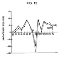
- Fig. 12 is a graph in which the first function and the second function are compared with each other.
- An embodiment of the present invention will be described below with reference to the drawings. As illustrated in Figs. 1 to 3, a light-emitting device 1 obtained by a manufacturing method according to the present embodiment has a light-emitting
chip 11 and alight emitter 12. The light-emittingchip 11 is a light-emitting diode made of a semiconductor material. Thelight emitter 12 includes a plurality of fluorescent materials being excited by a light emitted from the light-emittingchip 11. The light-emitting device 1 further has atransparent material layer 13 in which the light-emittingchip 11 is encapsulated. - Referring to Fig. 4, the manufacturing method according to the present embodiment includes Steps A to C. In Step A, a secondary mixture composition of the fluorescent materials is determined. In Step B, the
light emitter 12 is prepared on the basis of the secondary mixture composition. The plurality of fluorescence materials is mixed on the basis of the secondary mixture composition. The plurality of fluorescence materials mixed on the basis of the secondary mixture composition is putted in a transparent material. The transparent material is silicone resin. In Step C, the light-emitting device 1 having thelight emitter 12 is manufactured. The light-emittingchip 11 is mounted on a base. Thelight emitter 12 is placed on or above the light-emittingchip 11. - In Step A, the secondary mixture composition of the fluorescent materials is determined on the basis of a first function and a second function. The first function is determined on the basis of the relationship between a reference light and an objective light. The second function is determined on the basis of the relationship between the reference light and a light emitted from the fluorescent materials mixed at a primary mixture composition. In the present embodiment, "reference light" functions as a reference with respect to the objective light and the light emitted from the fluorescent materials. In addition, "objective light" is a design target light. In other words, the objective light corresponds to light desired by a user. As illustrated in Fig. 5, Step A illustrated in Fig. 4 includes the following Steps A1 to A4:
- Step A1: calculating the first function;
- Step A2: calculating the second function;
- Step A3: comparing the first function and the second function with each other; and
- Step A4: determining the secondary mixture composition of the fluorescent materials.
- The first function denotes the relationship between the reference light and the objective light. The first function is expressed as a function based on a plurality of test colors and calculated values of light intensities. The first function is obtained by the
following Steps 11 to 13. Instep 11, a first plurality of light intensities Sr(T) is calculated. The first plurality of light intensities Sr(T) corresponds to a plurality of test colors T1 to Tn (2 ≤ n), in the reference light. The first plurality of light intensities Sr(T) comprises Sr(T1), Sr(T2), ..., Sr(Tn-1) and Sr(Tn). The first plurality of light intensities Sr(T) is calculated by a method of specifying color rendering properties. - In
step 12, a second plurality of light intensities Sb(T) is calculated. The second plurality of light intensities corresponds to the test colors T1 to Tn (2 ≤ n), in the objective light. The second plurality of light intensities Sb(T) comprises Sb(T1), Sb(T2), ..., Sb(Tn-1) and Sb(Tn). The second plurality of light intensities Sb(T) is calculated by the method of specifying color rendering properties. - In
step 13, a first plurality of relative values S1(T) is calculated. The first plurality of relative values S1(T) denotes relativity of the calculated values of the second plurality of light intensities Sb(T) with respect to the calculated values of the first plurality of light intensities Sr(T). The first relative values S1(T) comprises S1 (T1), S1 (T2), ..., S1 (Tn-1) and S1 (Tn). The first function is defined by the first plurality of relative values S1(T). - The second function denotes the relationship between the reference light and the light emitted from the fluorescent materials mixed at the primary mixture composition. The second function is expressed as a function based on a plurality of test colors and calculated values of light intensities. The second function is obtained by the following
Steps 21 to 23. Instep 21, the first plurality of light intensities Sr(T) is calculated. The first plurality of light intensities corresponds to the test colors T1 to Tn (2 ≤ n), in the reference light. The first plurality of light intensities Sr(T) comprises Sr(T1), Sr(T2), ..., Sr(Tn-1) and Sr(Tn). - In
step 22, a third plurality of light intensities Sf(T) is calculated. The third plurality of light intensities Sf(T) corresponds to the test colors T1 to Tn (2 ≤ n), in the light emitted from the fluorescent materials mixed at the primary mixture composition. The third plurality of light intensities Sf(T) comprises Sf(T1), Sf(T2), ..., Sf(Tn-1) and Sf(Tn). The third plurality of light intensities Sf(T) is calculated by the method of specifying color rendering properties. - In
step 23, a second plurality of relative values S2(T) is calculated. The second plurality of relative values S2(T) denotes relativity of the calculated values of the third plurality of light intensities with respect to the calculated values of the first plurality of light intensities. The second plurality of relative values S2(T) comprises S2(T1), S2(T2), ... , S2 (Tn-1) and S2(Tn). The second function is defined by the second plurality of relative values S2(T). - In Steps A3 and A4, the secondary mixture composition of the fluorescent materials is determined on the basis of the result of comparison between the first function S1(T) and the second function S2(T).
- Examples of Steps A1 to A4 illustrated in Fig. 5 will now be described with reference to Figs. 6 to 12. Referring to Fig. 6, the reference light is the CIE standard illuminant D65 defined by ISO/CIE 10526. The CIE standard illuminant D65 has a color temperature of 6504 degree Kelvin. Another example of reference light is CIE standard illuminant A defined by ISO/CIE 10526. The CIE standard illuminant A has a color temperature of 2856 degree Kelvin. Another example of reference light is light having a color temperature of 2800 degree Kelvin, which corresponds to the color temperature of incandescent light. The test colors are the fourteen CIE-Munsell samples (R1, R2, ..., R13, R14). In the present embodiment, the test colors also include the CIE 1974 general color rendering index Ra. The general color rendering index Ra denotes an average value of test colors R1 to R14. The objective spectrum of the objective light is illustrated in Fig. 7.
- As illustrated in Fig. 8, Step A1 includes the following
Steps 11 to 13. InStep 11, a first plurality of light intensities Sr(R) is calculated. The first plurality of light intensities Sr(R) corresponds to a plurality of test colors, in the reference light (D65). The plurality of test colors comprises CIE-Munsell samples (R1, R2, ..., R13, R14) and general color rendering index Ra. The first plurality of light intensities Sr(R) comprises Sr(R1), Sr(R2), ..., Sr(R13), Sr(R14) and Sr(Ra). The first plurality of light intensities Sr(R) is calculated by a method of specifying color rendering properties defined by Japanese Industrial Standards (JIS) Z 8726. - In
step 12, calculated is a second plurality of light intensities Sb(R) corresponding to the plurality of test colors, in the objective light. The plurality of test colors comprises CIE-Munsell samples (R1, R2, ..., R13, R14) and general color rendering index Ra. The second plurality of light intensities Sb(R) comprises Sb(R1), Sb(R2), ..., Sb(R13), Sb(R14) and Sb(Ra). The second plurality of light intensities Sb(R) is calculated by the method of specifying color rendering properties defined by JIS Z 8726. - In
step 13, a first plurality of relative values S1(R) is calculated. The first plurality of relative values denotes relativity of the second plurality of light intensities Sb(R) with respect to the first plurality of light intensities Sr(R). The first plurality of relative values S1(R) comprises S1(R1), S1(R2), ..., S1(R13), S1(R14) and S1(Ra). The first function is defined by the first plurality of relative values S1(R). Fig. 9 illustrates the first function S1(R). - As illustrated in Fig. 10, Step A2 includes the following
Steps 21 to 23. InStep 21, the first plurality of light intensities Sr(R) is calculated. The first plurality of light intensities corresponds to the plurality of test colors, in the reference light (D65). The plurality of test colors comprises CIE-Munsell samples (R1, R2, ..., R13, R14) and general color rendering index Ra. The first plurality of light intensities Sr(R) comprises Sr(R1), Sr(R2), ..., Sr(R13), Sr(R14) and Sr (Ra) . The first plurality of light intensities Sr(R) is calculated by the method of specifying color rendering properties defined by JIS Z 8726. - In
Step 22, a third plurality of light intensities Sf(R) is calculated. The third plurality of light intensities corresponds to the plurality of test colors, in the light emitted from the fluorescent materials mixed at the primary mixture composition. The plurality of test colors comprises CIE-Munsell samples (R1, R2, ..., R13, R14) and general color rendering index Ra. The third plurality of light intensities Sf(R) comprises Sf (R1), Sf(R2), ..., Sf (R13), Sf (R14) and Sf(Ra). - In
Step 23, a second plurality of relative values S2(R) is calculated. The second plurality of relative values S2(R) denotes relativity of the third plurality of light intensities Sf(R) with respect to the first plurality of light intensities Sr(R). The second plurality of relative values S2(R) comprises S2(R1), S2(R2), ..., S2(R13), S2(R14) and S2(Ra). The second function is defined by the second plurality of relative values S2(R). Fig. 11 illustrates the second function S2(R). - As illustrated in Fig. 12, in Step A3, the first function and the second function are compared with each other. In Step A4, the secondary mixture composition of the fluorescent materials is determined on the basis of the result of comparison between the first function and the second function (S1(R)-S2(R)). The secondary mixture composition of the fluorescent materials is determined such that the second function S2(R) approximates the first function S1(R).
Claims (16)
- A method for determining a mixture composition of a plurality of fluorescent materials being excited by light emitted from a light-emitting chip made of a semiconductor material, the method comprising:calculating a first function by comparing an objective spectrum of an objective light with a reference spectrum of a reference light;calculating a second function by comparing a primary spectrum of the plurality of fluorescent materials mixed at a primary mixture composition with the reference spectrum; anddetermining a secondary mixture composition of the plurality of fluorescent materials on the basis of the result of comparison between the first function and the second function.
- The method according to claim 1, wherein the calculating the first function comprises:calculating a first plurality of light intensities corresponding to a plurality of test colors, in the reference light; andcalculating a second plurality of light intensities corresponding to the plurality of test colors, in the objective light.
- The method according to claim 2, wherein the calculating the first function further comprises calculating a first plurality of relative values of the second plurality of light intensities with respect to the first plurality of light intensities.
- The method according to claim 3, wherein the calculating the second function comprises calculating a third plurality of light intensities corresponding to the plurality of test colors, in a light emitted from the plurality of fluorescent materials mixed at the primary mixture composition.
- The method according to claim 4, wherein the calculating the second function further comprises calculating a second plurality of relative values of the third plurality of light intensities with respect to the first plurality of light intensities.
- The method according to claim 2, wherein the plurality of test colors includes CIE test colors.
- The method according to claim 6, wherein the plurality of test colors includes the CIE test colors R1 to R8.
- The method according to claim 2, wherein the plurality of test colors includes a general color rendering index.
- The method according to claim 2, wherein the first plurality of light intensities and the second plurality of light intensities are calculated by a method of specifying color rendering properties defined by JIS Z 8726.
- The method according to claim 1, wherein the reference light has a color temperature of 2800 K.
- The method according to claim 1, wherein the reference light is the CIE standard illuminant D65.
- A method for manufacturing a light-emitting device including a light-emitting chip made of a semiconductor material, the method comprising:determining a secondary mixture composition of a plurality of fluorescent materials on the basis of a first function and a second function, the first function denoting a relative relationship between a reference light and an objective light, the second function denoting a relative relationship between the reference light and a light emitted from the plurality of fluorescent materials mixed at a primary mixture composition;preparing a light emitter including the plurality of fluorescent materials on the basis of the secondary mixture composition;mounting the light-emitting chip on a base; andplacing the light emitter on or above the light-emitting chip.
- The method according to claim 12, wherein the first function is calculated by comparing an objective spectrum of the objective light with a reference spectrum of the reference light.
- The method according to claim 13, wherein the second function is calculated by comparing a primary spectrum of the plurality of fluorescent materials mixed at a primary mixture composition with the reference spectrum.
- The method according to claim 12, wherein the preparing the light emitter includes mixing the plurality of fluorescent materials on the basis of the secondary mixture composition.
- The method according to claim 15, wherein the preparing the light emitter further includes putting the plurality of fluorescent materials mixed on the basis of the secondary mixture composition in a transparent materials.
Applications Claiming Priority (1)
| Application Number | Priority Date | Filing Date | Title |
|---|---|---|---|
| JP2006293990A JP2008112811A (en) | 2006-10-30 | 2006-10-30 | Method for manufacturing light emitting device |
Publications (2)
| Publication Number | Publication Date |
|---|---|
| EP1919003A2 true EP1919003A2 (en) | 2008-05-07 |
| EP1919003A3 EP1919003A3 (en) | 2014-03-19 |
Family
ID=38988393
Family Applications (1)
| Application Number | Title | Priority Date | Filing Date |
|---|---|---|---|
| EP07021187.5A Withdrawn EP1919003A3 (en) | 2006-10-30 | 2007-10-30 | Method for determining mixture composition of fluorescent materials and method for manufacturing light-emitting device |
Country Status (3)
| Country | Link |
|---|---|
| US (1) | US7728970B2 (en) |
| EP (1) | EP1919003A3 (en) |
| JP (1) | JP2008112811A (en) |
Families Citing this family (12)
| Publication number | Priority date | Publication date | Assignee | Title |
|---|---|---|---|---|
| JP2011040495A (en) * | 2009-08-07 | 2011-02-24 | Koito Mfg Co Ltd | Light emitting module |
| KR101650375B1 (en) * | 2009-11-17 | 2016-08-24 | 주식회사 탑 엔지니어링 | Light Emitting Diode Repair Method and Apparatus using Quantum Dot Coating |
| JP2013048130A (en) * | 2011-08-29 | 2013-03-07 | Panasonic Corp | Resin coating device and resin coating method |
| EP2753150A4 (en) | 2011-09-02 | 2016-05-18 | Citizen Electronics | LIGHTING METHOD, AND LUMINESCENT DEVICE |
| WO2013031943A1 (en) | 2011-09-02 | 2013-03-07 | 三菱化学株式会社 | Lighting method and light-emitting device |
| JP2014093419A (en) * | 2012-11-02 | 2014-05-19 | Panasonic Corp | Manufacturing method of light-emitting device and light-emitting device |
| CN104885571B (en) | 2013-03-04 | 2017-06-09 | 西铁城电子株式会社 | Light-emitting device, design method of light-emitting device, driving method of light-emitting device, lighting method, and manufacturing method of light-emitting device |
| CN105849920B (en) | 2013-12-27 | 2020-11-06 | 西铁城电子株式会社 | Light emitting device and method for designing light emitting device |
| JP6356018B2 (en) * | 2014-09-03 | 2018-07-11 | シチズン電子株式会社 | LIGHT EMITTING DEVICE AND LIGHT EMITTING DEVICE MANUFACTURING METHOD |
| JP6356005B2 (en) * | 2013-12-27 | 2018-07-11 | シチズン電子株式会社 | LIGHT EMITTING DEVICE AND LIGHT EMITTING DEVICE DESIGN METHOD |
| JP6666064B2 (en) * | 2014-09-03 | 2020-03-13 | シチズン電子株式会社 | Light emitting device including semiconductor light emitting element and lighting method |
| CN111554790B (en) * | 2013-12-27 | 2023-09-15 | 西铁城电子株式会社 | Design method of lighting device |
Family Cites Families (3)
| Publication number | Priority date | Publication date | Assignee | Title |
|---|---|---|---|---|
| US6686691B1 (en) * | 1999-09-27 | 2004-02-03 | Lumileds Lighting, U.S., Llc | Tri-color, white light LED lamps |
| JP4543253B2 (en) * | 2004-10-28 | 2010-09-15 | Dowaエレクトロニクス株式会社 | Phosphor mixture and light emitting device |
| JP4104013B2 (en) * | 2005-03-18 | 2008-06-18 | 株式会社フジクラ | LIGHT EMITTING DEVICE AND LIGHTING DEVICE |
-
2006
- 2006-10-30 JP JP2006293990A patent/JP2008112811A/en active Pending
-
2007
- 2007-10-30 EP EP07021187.5A patent/EP1919003A3/en not_active Withdrawn
- 2007-10-30 US US11/928,822 patent/US7728970B2/en not_active Expired - Fee Related
Non-Patent Citations (1)
| Title |
|---|
| "Method of specifying colour rendering properties of light sources - English translation", JAPANESE INDUSTIRAL STANDARD, JAPANESE STANDARD ASSOCIATION, vol. JIS Z 8726:1990, 1 January 1990 (1990-01-01), pages 1 - 18, XP009500818 * |
Also Published As
| Publication number | Publication date |
|---|---|
| JP2008112811A (en) | 2008-05-15 |
| US7728970B2 (en) | 2010-06-01 |
| US20080106734A1 (en) | 2008-05-08 |
| EP1919003A3 (en) | 2014-03-19 |
Similar Documents
| Publication | Publication Date | Title |
|---|---|---|
| EP1919003A2 (en) | Method for determining mixture composition of fluorescent materials and method for manufacturing light-emitting device | |
| JP4989936B2 (en) | Lighting device | |
| EP3382755B1 (en) | White light emitting module | |
| US8192047B2 (en) | High color rendering index white LED light system using multi-wavelength pump sources and mixed phosphors | |
| US9871173B2 (en) | Light emitting devices having closely-spaced broad-spectrum and narrow-spectrum luminescent materials and related methods | |
| US6858456B2 (en) | Method for manufacturing a light emitting device | |
| US7462983B2 (en) | White light emitting device | |
| US10208943B2 (en) | Lamps for enhanced optical brightening and color preference | |
| US9070843B2 (en) | Semiconductor light-emitting device, exhibit-irradiating illumination device, meat-irradiating illumination device, vegetable-irradiating illumination device, fresh fish-irradiating illumination device, general-purpose illumination device, and semiconductor light-emitting system | |
| EP2672532A1 (en) | Led module and illumination device | |
| US8436526B2 (en) | Multiwavelength solid-state lamps with an enhanced number of rendered colors | |
| CN103717705A (en) | Gallium-substituted yttrium aluminum garnet phosphor and light-emitting devices incorporating it | |
| US9370072B2 (en) | Solid-state sources of light for preferential colour rendition | |
| CN107643613B (en) | Method for determining chromaticity level of light emitting device | |
| JP6520553B2 (en) | Light emitting device | |
| US9985009B2 (en) | Manufacturing method of LED light emitting device | |
| US8222652B2 (en) | Method for controlling color accuracy in a light-emitting semiconductor-based device and process for producing a light-emitting semiconductor-based device with controlled color accuracy | |
| RU2651794C2 (en) | Dimable light emitting arrangement | |
| US8876312B2 (en) | Lighting device and apparatus with spectral converter within a casing | |
| JP6354607B2 (en) | Light emitting device | |
| EP1994570A1 (en) | Light-emitting diode module | |
| JP2017522412A (en) | Phosphor composition and lighting fixture comprising the same | |
| JP2020198345A (en) | Light-emitting device manufacturing method | |
| JP2006324653A (en) | Light emitting device, liquid crystal display device and lighting device | |
| EP4073838A1 (en) | Leds and multi-color phosphors |
Legal Events
| Date | Code | Title | Description |
|---|---|---|---|
| PUAI | Public reference made under article 153(3) epc to a published international application that has entered the european phase |
Free format text: ORIGINAL CODE: 0009012 |
|
| AK | Designated contracting states |
Kind code of ref document: A2 Designated state(s): AT BE BG CH CY CZ DE DK EE ES FI FR GB GR HU IE IS IT LI LT LU LV MC MT NL PL PT RO SE SI SK TR |
|
| AX | Request for extension of the european patent |
Extension state: AL BA HR MK RS |
|
| PUAL | Search report despatched |
Free format text: ORIGINAL CODE: 0009013 |
|
| AK | Designated contracting states |
Kind code of ref document: A3 Designated state(s): AT BE BG CH CY CZ DE DK EE ES FI FR GB GR HU IE IS IT LI LT LU LV MC MT NL PL PT RO SE SI SK TR |
|
| AX | Request for extension of the european patent |
Extension state: AL BA HR MK RS |
|
| RIC1 | Information provided on ipc code assigned before grant |
Ipc: H01L 33/00 20100101AFI20140207BHEP Ipc: H01L 33/50 20100101ALI20140207BHEP |
|
| 17P | Request for examination filed |
Effective date: 20140826 |
|
| RBV | Designated contracting states (corrected) |
Designated state(s): AT BE BG CH CY CZ DE DK EE ES FI FR GB GR HU IE IS IT LI LT LU LV MC MT NL PL PT RO SE SI SK TR |
|
| AKX | Designation fees paid |
Designated state(s): DE FR GB |
|
| 17Q | First examination report despatched |
Effective date: 20171027 |
|
| STAA | Information on the status of an ep patent application or granted ep patent |
Free format text: STATUS: THE APPLICATION HAS BEEN WITHDRAWN |
|
| 18W | Application withdrawn |
Effective date: 20180222 |