EP1915071B1 - Scharnier für eine bettgestellanordnung - Google Patents
Scharnier für eine bettgestellanordnung Download PDFInfo
- Publication number
- EP1915071B1 EP1915071B1 EP06764995A EP06764995A EP1915071B1 EP 1915071 B1 EP1915071 B1 EP 1915071B1 EP 06764995 A EP06764995 A EP 06764995A EP 06764995 A EP06764995 A EP 06764995A EP 1915071 B1 EP1915071 B1 EP 1915071B1
- Authority
- EP
- European Patent Office
- Prior art keywords
- hinge
- assembly
- frame
- frame assembly
- electrically conductive
- Prior art date
- Legal status (The legal status is an assumption and is not a legal conclusion. Google has not performed a legal analysis and makes no representation as to the accuracy of the status listed.)
- Active
Links
Images


Classifications
-
- A—HUMAN NECESSITIES
- A61—MEDICAL OR VETERINARY SCIENCE; HYGIENE
- A61G—TRANSPORT, PERSONAL CONVEYANCES, OR ACCOMMODATION SPECIALLY ADAPTED FOR PATIENTS OR DISABLED PERSONS; OPERATING TABLES OR CHAIRS; CHAIRS FOR DENTISTRY; FUNERAL DEVICES
- A61G7/00—Beds specially adapted for nursing; Devices for lifting patients or disabled persons
- A61G7/002—Beds specially adapted for nursing; Devices for lifting patients or disabled persons having adjustable mattress frame
- A61G7/015—Beds specially adapted for nursing; Devices for lifting patients or disabled persons having adjustable mattress frame divided into different adjustable sections, e.g. for Gatch position
-
- A—HUMAN NECESSITIES
- A61—MEDICAL OR VETERINARY SCIENCE; HYGIENE
- A61G—TRANSPORT, PERSONAL CONVEYANCES, OR ACCOMMODATION SPECIALLY ADAPTED FOR PATIENTS OR DISABLED PERSONS; OPERATING TABLES OR CHAIRS; CHAIRS FOR DENTISTRY; FUNERAL DEVICES
- A61G7/00—Beds specially adapted for nursing; Devices for lifting patients or disabled persons
- A61G7/05—Parts, details or accessories of beds
- A61G7/0507—Side-rails
- A61G7/0512—Side-rails characterised by customised length
- A61G7/0513—Side-rails characterised by customised length covering particular sections of the bed, e.g. one or more partial side-rail sections along the bed
-
- E—FIXED CONSTRUCTIONS
- E05—LOCKS; KEYS; WINDOW OR DOOR FITTINGS; SAFES
- E05D—HINGES OR SUSPENSION DEVICES FOR DOORS, WINDOWS OR WINGS
- E05D11/00—Additional features or accessories of hinges
- E05D11/10—Devices for preventing movement between relatively-movable hinge parts
- E05D11/1028—Devices for preventing movement between relatively-movable hinge parts for maintaining the hinge in two or more positions, e.g. intermediate or fully open
Definitions
- the present invention relates to a bed frame assembly and in particular to a hinge structure for a configurable bed frame.
- Configurable bed frame assemblies have been known for many years. These are provided with a bed frame formed of various portions which can be pivoted relative to one another to configure the bed from a flat configuration to different raised configurations. Typically, the portions include a back rest, a thigh rest and a leg rest. Some beds are also provided with a seat rest between the back rest and the thigh rest. The various portions can be moved or pivoted to raise a patient into a sitting position, to raise a patient's legs only to assist in vascular flow and so on.
- Such configurable beds have also for many years been controlled electrically, being provided with a plurality of electrically operated actuators which allow for the bed configuration to be changed by pressing one or more buttons on a key pad. Electrical systems are increasingly being incorporated into such beds to provide other functions and facilities.
- the various portions of the bed are typically connected by hinges, either directly to one another or through connecting elements such as supports integral with a bed sub-frame.
- the hinges are typically provided by bolts and nuts passing through two or more circular apertures in adjacent frame elements or brackets to be coupled pivotally together.
- These hinges can cause a number of problems in maintaining the bed, particularly in a hospital or care home environment.
- the hinges tend to form protrusions beyond the pivoted frame elements, which must be covered in order to protect patients and users and also to prevent the accumulation of dirt at the site of the hinges.
- tarpaulins or other covers is commonplace in the industry.
- DE3516081 discloses a bed where the hinges do not protrude beyond the pivoted frame elements. However the dirt can accumulate between the hinge parts.
- the present invention seeks to provide an improved bed assembly and hinge structure of a bed assembly.
- substantially flat surface is intended to refer to a surface which does not present a substantial protrusion from the frame struts which could trap dirt or which requires physical separation from a user such as by a cover or tarpaulin.
- the hinge has an outer perimeter which presents a substantially flat surface without any connections with all of outer surfaces of the frame struts to which it connects.
- the hinge connecting members are able to fit within tubular frame struts.
- the connecting members are able to fit over an outer surface of the frame struts.
- the first and second hinge parts have internal hinge couplings.
- no hinge coupling element needs to be provided outside of the flush outer perimeter of the hinge assembly.
- the hinge assembly is electrically conductive such that a conductive path is provided through the assembly from one of the connecting members to the other. This enables the hinge to provide the electrical coupling between adjacent frame struts without the need for separate electrical wires.
- the hinge assembly includes an electrically conductive hinge bush provided between the first and second hinge parts.
- the bush is preferably an interference fit with one of the hinge parts and abuts the other hinge part.
- the bush assists in providing a reliable electrical path between the first and second hinge parts and it has been found that this is more than sufficient and permanent.
- the hinge assembly will be provided with an electrically conductive spring element therewithin.
- the spring element in one embodiment is a coil spring located around the bush and abutting internal walls of the first and second hinge parts. In another embodiment, the spring element is located between the bush and one of the hinge parts, for example a Belleville spring or similar.
- first and second connecting members are provided with a fastening element, in the preferred embodiment an aperture able to receive an electrically conductive rivet or other electrically conductive fastener which would fasten together the hinge connectors to their respective frame strut, thereby providing an even more secure mechanical and electrical coupling.
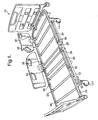
- bed assembly 10 which includes a wheeled base 12 provided with four castors 14 of conventional type. Coupled to the base 12 is a bed platform 20 which can be raised and lowered relative to the base 12 and tilted by means of one or more electrical actuators (not shown), also of conventional type.
- the platform 20 is provided with a frame 22 formed, in this embodiment, of four frame sections 24, 26, 28 and 30 which are coupled to one another by means of hinged joints 32, 34 and 36.
- Each frame section 24-30 is provided with an upper frame member having substantially vertical inner side walls 38 and a plurality of depending transverse struts 40 to form a recessed support surface for supporting a plurality of mattress support panels, described in the applicant's co-pending British patent application numbers 0514926.5 and 0523184.0 .
- the hinges 32, 34 and 36 are provided in the upper frame members 24-30 and enable the frame members to pivot relative to one another about the hinges 32-36.
- the frame 22 is typically made of metal or a metal alloy.
- the frame struts are, in this embodiment, tubular but could be substantially solid if preferred.
- the frame sections 24-30 are formed from struts which are of rounded rectangular form in transverse cross-section.
- any other cross-section could be used but it is preferred that the outer form is smooth and has rounded corners.
- a circular outer profile is a suitable alternative.
- the hinges 32-36 have an outer form which complements the outer form of the frame struts and present substantially flat inner and outer surfaces to the frame 20. There are no features of the hinges which protrude laterally beyond the frame sections to require special provision such as covering to protect a patient or care staff.
- Each hinge which is made substantially entirely of metal, is formed of first and second metal or metal alloy hinge halves 50, 52 which are externally substantially identical to each other although this is not strictly necessary.
- Each hinge half 50, 52 includes a connector element 54, 56 of a rounded rectangular outer form which is of a size to fit tightly within the inner cavity of the tubular frame struts 24-30.
- a connector element 54, 56 of a rounded rectangular outer form which is of a size to fit tightly within the inner cavity of the tubular frame struts 24-30.
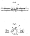
- Each connecting element 54, 56 is also provided with a circular aperture 60 which in use receives a metal rivet 55, 57 (shown in Figure 3 ) or other suitable fastener which passes through a corresponding aligned hole in the associated frame strut.
- a metal rivet 55, 57 shown in Figure 3
- Such rivet or other fastener can fix the two elements together and guarantee a good electrical coupling, although this feature is not always necessary.
- a rivet is preferred because of improved assembly and because it can provide a smooth rounded outer surface, which is not possible with a bolt or the like.
- the connecting elements 54, 56 are integral with their respective hinge body members 62, 64, which members provide a shoulder 66, 68 at the junction with their respective connecting element 54, 56 of a height substantially identical to the thickness of the tubular strut such that the outer surface of the body members 62, 64 provides a substantially smooth transition from the outer surfaces of the frame struts to the outer surface of the hinge 32-36, as can be seen in Figure 3 .
- the hinge half 50 includes an inner tubular section 70 which provides a shoulder 72 which itself is at the base of a tubular recess 74.
- the hinge half 52 includes an inner annular wall 76 circumscribing an annular boss 78, which boss is provided with a round aperture 80 therein. Coupling the wall 76 to the outer wall 82 of the hinge half 52 are a plurality of radially spaced strengthening ribs 82. Similar ribs may be provided in the hinge half 50 between the walls 70 and 74 and the outer wall of that hinge half.
- the space between the wall 76 and the boss 78 of the hinge half 52 presents an annular base wall 84.
- a hinge bush 86 made of metal or metal alloy in this embodiment, includes an annular base 88 and an upstanding annular wall 90 which is provided with a plurality of radially spaced longitudinally extending ribs 92.
- the annular base 88 of the hinge bush 86 fits into the recess formed by the wall 76 and boss 78 of the hinge half 52 and when assembled touches in rotatable manner the base wall 84, as best seen in Figure 3 .
- the upstanding annular wall 90 is an interference fit into the annular wall 70 of the hinge half 50 and in practice rotates with that hinge half.
- the assembly includes a washer 94 which, when fitted, sits on the shoulder 72 and which provides an upper stop to the position o the upstanding wall 90 of the bush 86.
- a screw fixing in this example a button head screw 96 fits through the aperture 98 of the washer 94 and, in the preferred embodiment, engages with threads of threaded aperture 80 in the boss 78 of the hinge half 52.
- the screw 96 has an internally threaded bore (not shown) which is then fixed to a bolt fitted into the boss 78 from the underside of the hinge half 52 when viewed in the orientation of Figure 2 .
- the washer 94 acts to urge the bush 86 against the base wall 84 of the hinge half 52, for which the upstanding wall 90 is designed to be suitably high, thereby ensuring a consistent and reliable contact and thus in practice a reliable electrical connection between the two hinge halves 50, 52.
- all the components of the hinges 32-36 are preferably of conductive material, a plurality of conductive paths is typically present, thereby ensuring a good electrical connection during all the positions of the hinge.
- an electrically conductive sprung element within the hinge assembly.
- a coil spring which would fit around the upstanding wall 90 of the bushing and within the annular wall 70, of such dimensions that it is compressed against the inner surface of annular wall 76 of the hinge half 52 and against the inner surface of a similar wall (not shown) in the hinge half 50, in a manner which would be immediately apparent to a person skilled in the art.
- a Belleville spring or washer could be placed between the base wall 84 of the hinge half 52 and the annular base 88 of the bush 86.
- First and second cover panels 100, 102 fit over the recesses provided by the walls 74 and of the boss 78 (on the underside of the hinge half 52 when viewed in the orientation of Figure 2 ) to provide a smooth outer surface to the hinge assembly.
- These cover panels could be of any suitable material and their coupling to the hinge body will be apparent to the skilled person, there being a variety of fixing methods known in the art.
- FIG 4 there is shown a front view of the hinge of Figure 2 in assembled form.
- the hinge cover 100 is provided with a plurality of angle markings 104. These note the angle between the two hinge halves 50, 52 and in practice between two frame struts coupled together by the hinge 32-36, as shown in Figure 5 . Such markings are useful during the assembly of the bed frame.
- hinge assemblies are shown as fitting into the bed frame sections, it is envisaged that this coupling could be reversed.
- the connecting members of the hinge halves could fit over the ends of respective frame struts, which struts could be provided with ends of reduced outer dimensions to provide shoulders similar to the shoulders 66, 68 shown in Figure 2 .
- the hinge assembly and its various components could be made of a material other than metal or metal alloy as long it can conduct electricity from one frame strut to another.
Landscapes
- Health & Medical Sciences (AREA)
- Nursing (AREA)
- Life Sciences & Earth Sciences (AREA)
- Animal Behavior & Ethology (AREA)
- General Health & Medical Sciences (AREA)
- Public Health (AREA)
- Veterinary Medicine (AREA)
- Pivots And Pivotal Connections (AREA)
- Invalid Beds And Related Equipment (AREA)
Claims (12)
- Gestellanordnung (22) für ein konfigurierbares Bett (10), die eine Anzahl von bewegbaren Gestellteilen (24, 26, 28, 30), die aus einer oder mehreren Gestellstreben gebildet sind, und eine Gelenkanordnung (32, 34, 36) umfasst, die erste und zweite Gelenkteile (50, 52) einschließt, die jeweils mit einem integralen Verbindungsglied (54, 56) versehen sind, wobei jedes Verbindungsglied fähig ist, an jeweilige Gestellstreben (24-30) zu passen, das Gelenk einen Außenumfang aufweist, der eine im Wesentlichen flache Oberfläche mit einer oder mehr Außenflächen der Gestellstreben, mit denen es verbunden ist, präsentiert, dadurch gekennzeichnet, dass die Gelenkanordnung (32, 34, 36) mit einer oder mehr Winkelmarkierungen (104) versehen ist, die zum Anzeigen des Schwenkwinkelsder Gelenkanordnung betreibbar sind.
- Gestellanordnung (22) gemäß Anspruch 1, dadurch gekennzeichnet, dass die Gestellstreben (24-30) rohrförmig sind und die Gelenkverbindungsglieder (54, 56) fähig sind, in die rohrförmigen Gestellstreben zu passen.
- Gestellanordnung (22) gemäß Anspruch 1 oder 2, dadurch gekennzeichnet, dass die ersten und zweiten Gelenkteile (50, 52) interne Gelenkverbindungen (76, 82) aufweisen.
- Gestellanordnung (22) gemäß Anspruch 1, 2 oder 3, dadurch gekennzeichnet, dass die Gelenkanordnung (32, 34, 36) elektrisch leitfähig ist, so dass ein leitender Weg von einem der Verbindungsglieder (54, 56) zu dem anderen vorgesehen ist.
- Gestellanordnung (22) gemäß Anspruch 4, dadurch gekennzeichnet, dass die Gelenkanordnung (32, 34, 36) eine elektrisch leitende Gelenkbuchse (86) einschließt, die zwischen den ersten und zweiten Gelenkteilen (50, 52) vorgesehen ist.
- Gestellanordnung (22) gemäß Anspruch 5, dadurch gekennzeichnet, dass die Buchse (86) eine Übermaßpassung mit einem der Gelenkteile (50) ist und an dem anderen Gelenkteil (52) anlegt.
- Gestellanordnung (22) gemäß Anspruch 4, 5 oder 6, die ein elektrisch leitendes Federelement darin einschließt.
- Gestellanordnung (22) gemäß Anspruch 7, dadurch gekennzeichnet, dass das Federelement eine Wickelfeder oder eine Tellerfeder ist.
- Gestellanordnung (22) gemäß einem der vorhergehenden Ansprüche, dadurch gekennzeichnet, dass die ersten und zweiten Verbindungsglieder mit einem Befestigungselement (58) versehen sind.
- Gestellanordnung (22) gemäß Anspruch 9, dadurch gekennzeichnet, dass das Befestigungselement eine Öffnung (60) ist, die fähig ist, eine elektrisch leitende Niete (55, 57) oder ein anderes elektrisch leitendes Befestigungselement aufzunehmen.
- Gestellanordnung (22) gemäß einem der vorhergehenden Ansprüche, dadurch gekennzeichnet, dass die Gelenkanordnung (32, 34, 36) erste und zweite Gelenkteile (50, 52) einschließt, die jeweils mit einem integralen Verbindungsglied (54, 56) versehen sind, wobei die Anordnung elektrisch leitend ist, so dass ein leitender Weg durch die Anordnung von einem Verbindungsglied zu dem anderen vorgesehen ist.
- Bett (10), das eine Gestellanordnung gemäß einem der vorhergehenden Ansprüche einschließt.
Applications Claiming Priority (3)
| Application Number | Priority Date | Filing Date | Title |
|---|---|---|---|
| GBGB0514926.5A GB0514926D0 (en) | 2005-07-20 | 2005-07-20 | Bed assembly |
| GBGB0523169.1A GB0523169D0 (en) | 2005-07-20 | 2005-11-14 | Bed frame assembly |
| PCT/GB2006/002653 WO2007010234A1 (en) | 2005-07-20 | 2006-07-17 | A hinge for bed frame assembly |
Publications (2)
| Publication Number | Publication Date |
|---|---|
| EP1915071A1 EP1915071A1 (de) | 2008-04-30 |
| EP1915071B1 true EP1915071B1 (de) | 2009-12-16 |
Family
ID=36942627
Family Applications (1)
| Application Number | Title | Priority Date | Filing Date |
|---|---|---|---|
| EP06764995A Active EP1915071B1 (de) | 2005-07-20 | 2006-07-17 | Scharnier für eine bettgestellanordnung |
Country Status (4)
| Country | Link |
|---|---|
| EP (1) | EP1915071B1 (de) |
| AU (1) | AU2006271419B2 (de) |
| CA (1) | CA2615957C (de) |
| WO (1) | WO2007010234A1 (de) |
Families Citing this family (5)
| Publication number | Priority date | Publication date | Assignee | Title |
|---|---|---|---|---|
| NL2001550C2 (nl) | 2008-05-06 | 2009-11-12 | Cornelis Franciscus De La Haye | Verstelbare spiraalmatrasdrager met afknelbeveiliging. |
| IT1394937B1 (it) | 2009-01-12 | 2012-07-27 | Mondo Spa | Procedimento per realizzare materiale di riempimento per manti erbosi sintetici, corrispondente materiale e relativo manto erboso sintetico |
| NL2017214B1 (en) | 2016-07-22 | 2018-01-31 | Synbra Tech B V | Artificial turf suitable for sports fields |
| NL2018864B1 (en) | 2017-05-08 | 2018-11-14 | Synbra Tech B V | Artificial turf suitable for sports fields |
| IT202100021329A1 (it) | 2021-08-05 | 2023-02-05 | Adalberto Principi | Processo per la realizzazione di materiale riempitivo per manti erbosi sintetici, relativa struttura e composizione |
Family Cites Families (7)
| Publication number | Priority date | Publication date | Assignee | Title |
|---|---|---|---|---|
| US3355695A (en) * | 1965-05-25 | 1967-11-28 | Joseph E Overesch | Hinge for carrying electric circuits |
| DE3516081A1 (de) * | 1985-05-04 | 1986-11-06 | Wilh. Berg GmbH & Co KG, 5990 Altena | Verfahren zur herstellung der matratzenrahmen von krankenbetten |
| US4805265A (en) * | 1986-09-25 | 1989-02-21 | Siemens Aktiengesellschaft | Hinge for fastening swivelably arranged electrotechnical appliances |
| IT233164Y1 (it) * | 1994-07-01 | 2000-01-26 | Gilpet S N C Di Luigi Giacalon | Brandina o cuccia pieghegole e/o smontabile. |
| BR9916131A (pt) * | 1998-12-11 | 2001-11-06 | Hill Rom Co Inc | Montagens de cama, de apoio de paciente para uma cama articulada e de manìpulo de empurrar articulado para camas de hospital, e, cama de hospital |
| DE19912335C2 (de) * | 1999-03-19 | 2001-02-08 | Bosch Gmbh Robert | Scharnier |
| EP1408190B1 (de) * | 2002-10-09 | 2006-07-12 | Steinbach & Vollmann GmbH & Co. KG | Türbandanordnung |
-
2006
- 2006-07-17 EP EP06764995A patent/EP1915071B1/de active Active
- 2006-07-17 CA CA2615957A patent/CA2615957C/en active Active
- 2006-07-17 AU AU2006271419A patent/AU2006271419B2/en not_active Ceased
- 2006-07-17 WO PCT/GB2006/002653 patent/WO2007010234A1/en not_active Ceased
Also Published As
| Publication number | Publication date |
|---|---|
| CA2615957A1 (en) | 2007-01-25 |
| AU2006271419B2 (en) | 2011-10-20 |
| CA2615957C (en) | 2014-08-26 |
| EP1915071A1 (de) | 2008-04-30 |
| AU2006271419A1 (en) | 2007-01-25 |
| WO2007010234A1 (en) | 2007-01-25 |
Similar Documents
| Publication | Publication Date | Title |
|---|---|---|
| US8397324B2 (en) | Hinge for bed frame assembly | |
| EP1765120B1 (de) | T-förmige seitenschienen für ein bettgestell | |
| EP1915071B1 (de) | Scharnier für eine bettgestellanordnung | |
| KR100799188B1 (ko) | 절첩식 의자 일체형 테이블 | |
| JP7788670B2 (ja) | 手すり装置及びベース | |
| CN106235712B (zh) | 用于可转变沙发的多级沙发铰链 | |
| AU2006271509B2 (en) | Bed assembly | |
| US6258128B1 (en) | Artificial leg having bearing with stopper | |
| JP6355238B2 (ja) | 椅子 | |
| JP6111446B2 (ja) | 昇降椅子 | |
| KR100802143B1 (ko) | 무릎 관절용 의지 | |
| KR200167511Y1 (ko) | 테이블 지지장치 | |
| WO2007054683A2 (en) | Actuator support system | |
| JP6479932B2 (ja) | 寝台装置 | |
| JP6239705B1 (ja) | 寝台装置 | |
| KR200327989Y1 (ko) | 의자 팔걸이 | |
| JP2023137269A (ja) | 組立式ベッド | |
| JPH0777583B2 (ja) | 移動用補助脚機構を備えたベッド | |
| HK1088649B (en) | Oil-less rivet system for a reclining chair mechanism and a pivoting linkage | |
| WO2002071996A1 (fr) | Siege a roulettes comportant des poignees de manutention |
Legal Events
| Date | Code | Title | Description |
|---|---|---|---|
| PUAI | Public reference made under article 153(3) epc to a published international application that has entered the european phase |
Free format text: ORIGINAL CODE: 0009012 |
|
| 17P | Request for examination filed |
Effective date: 20080116 |
|
| AK | Designated contracting states |
Kind code of ref document: A1 Designated state(s): AT BE BG CH CY CZ DE DK EE ES FI FR GB GR HU IE IS IT LI LT LU LV MC NL PL PT RO SE SI SK TR |
|
| 17Q | First examination report despatched |
Effective date: 20080523 |
|
| GRAP | Despatch of communication of intention to grant a patent |
Free format text: ORIGINAL CODE: EPIDOSNIGR1 |
|
| DAX | Request for extension of the european patent (deleted) | ||
| RIN1 | Information on inventor provided before grant (corrected) |
Inventor name: HOLLYOAK, STEPHEN Inventor name: HAYES, STEPHEN |
|
| GRAS | Grant fee paid |
Free format text: ORIGINAL CODE: EPIDOSNIGR3 |
|
| GRAA | (expected) grant |
Free format text: ORIGINAL CODE: 0009210 |
|
| AK | Designated contracting states |
Kind code of ref document: B1 Designated state(s): AT BE BG CH CY CZ DE DK EE ES FI FR GB GR HU IE IS IT LI LT LU LV MC NL PL PT RO SE SI SK TR |
|
| REG | Reference to a national code |
Ref country code: GB Ref legal event code: FG4D |
|
| REG | Reference to a national code |
Ref country code: CH Ref legal event code: EP |
|
| REG | Reference to a national code |
Ref country code: IE Ref legal event code: FG4D |
|
| REF | Corresponds to: |
Ref document number: 602006011175 Country of ref document: DE Date of ref document: 20100128 Kind code of ref document: P |
|
| REG | Reference to a national code |
Ref country code: NL Ref legal event code: VDEP Effective date: 20091216 |
|
| PG25 | Lapsed in a contracting state [announced via postgrant information from national office to epo] |
Ref country code: LT Free format text: LAPSE BECAUSE OF FAILURE TO SUBMIT A TRANSLATION OF THE DESCRIPTION OR TO PAY THE FEE WITHIN THE PRESCRIBED TIME-LIMIT Effective date: 20091216 Ref country code: FI Free format text: LAPSE BECAUSE OF FAILURE TO SUBMIT A TRANSLATION OF THE DESCRIPTION OR TO PAY THE FEE WITHIN THE PRESCRIBED TIME-LIMIT Effective date: 20091216 Ref country code: SE Free format text: LAPSE BECAUSE OF FAILURE TO SUBMIT A TRANSLATION OF THE DESCRIPTION OR TO PAY THE FEE WITHIN THE PRESCRIBED TIME-LIMIT Effective date: 20091216 |
|
| REG | Reference to a national code |
Ref country code: DK Ref legal event code: T3 |
|
| LTIE | Lt: invalidation of european patent or patent extension |
Effective date: 20091216 |
|
| PG25 | Lapsed in a contracting state [announced via postgrant information from national office to epo] |
Ref country code: SI Free format text: LAPSE BECAUSE OF FAILURE TO SUBMIT A TRANSLATION OF THE DESCRIPTION OR TO PAY THE FEE WITHIN THE PRESCRIBED TIME-LIMIT Effective date: 20091216 Ref country code: PL Free format text: LAPSE BECAUSE OF FAILURE TO SUBMIT A TRANSLATION OF THE DESCRIPTION OR TO PAY THE FEE WITHIN THE PRESCRIBED TIME-LIMIT Effective date: 20091216 Ref country code: LV Free format text: LAPSE BECAUSE OF FAILURE TO SUBMIT A TRANSLATION OF THE DESCRIPTION OR TO PAY THE FEE WITHIN THE PRESCRIBED TIME-LIMIT Effective date: 20091216 |
|
| PG25 | Lapsed in a contracting state [announced via postgrant information from national office to epo] |
Ref country code: AT Free format text: LAPSE BECAUSE OF FAILURE TO SUBMIT A TRANSLATION OF THE DESCRIPTION OR TO PAY THE FEE WITHIN THE PRESCRIBED TIME-LIMIT Effective date: 20091216 |
|
| PG25 | Lapsed in a contracting state [announced via postgrant information from national office to epo] |
Ref country code: RO Free format text: LAPSE BECAUSE OF FAILURE TO SUBMIT A TRANSLATION OF THE DESCRIPTION OR TO PAY THE FEE WITHIN THE PRESCRIBED TIME-LIMIT Effective date: 20091216 Ref country code: ES Free format text: LAPSE BECAUSE OF FAILURE TO SUBMIT A TRANSLATION OF THE DESCRIPTION OR TO PAY THE FEE WITHIN THE PRESCRIBED TIME-LIMIT Effective date: 20100327 Ref country code: IS Free format text: LAPSE BECAUSE OF FAILURE TO SUBMIT A TRANSLATION OF THE DESCRIPTION OR TO PAY THE FEE WITHIN THE PRESCRIBED TIME-LIMIT Effective date: 20100416 Ref country code: EE Free format text: LAPSE BECAUSE OF FAILURE TO SUBMIT A TRANSLATION OF THE DESCRIPTION OR TO PAY THE FEE WITHIN THE PRESCRIBED TIME-LIMIT Effective date: 20091216 Ref country code: PT Free format text: LAPSE BECAUSE OF FAILURE TO SUBMIT A TRANSLATION OF THE DESCRIPTION OR TO PAY THE FEE WITHIN THE PRESCRIBED TIME-LIMIT Effective date: 20100416 Ref country code: BG Free format text: LAPSE BECAUSE OF FAILURE TO SUBMIT A TRANSLATION OF THE DESCRIPTION OR TO PAY THE FEE WITHIN THE PRESCRIBED TIME-LIMIT Effective date: 20100316 Ref country code: NL Free format text: LAPSE BECAUSE OF FAILURE TO SUBMIT A TRANSLATION OF THE DESCRIPTION OR TO PAY THE FEE WITHIN THE PRESCRIBED TIME-LIMIT Effective date: 20091216 |
|
| PG25 | Lapsed in a contracting state [announced via postgrant information from national office to epo] |
Ref country code: CZ Free format text: LAPSE BECAUSE OF FAILURE TO SUBMIT A TRANSLATION OF THE DESCRIPTION OR TO PAY THE FEE WITHIN THE PRESCRIBED TIME-LIMIT Effective date: 20091216 Ref country code: SK Free format text: LAPSE BECAUSE OF FAILURE TO SUBMIT A TRANSLATION OF THE DESCRIPTION OR TO PAY THE FEE WITHIN THE PRESCRIBED TIME-LIMIT Effective date: 20091216 Ref country code: BE Free format text: LAPSE BECAUSE OF FAILURE TO SUBMIT A TRANSLATION OF THE DESCRIPTION OR TO PAY THE FEE WITHIN THE PRESCRIBED TIME-LIMIT Effective date: 20091216 |
|
| PLBE | No opposition filed within time limit |
Free format text: ORIGINAL CODE: 0009261 |
|
| STAA | Information on the status of an ep patent application or granted ep patent |
Free format text: STATUS: NO OPPOSITION FILED WITHIN TIME LIMIT |
|
| PG25 | Lapsed in a contracting state [announced via postgrant information from national office to epo] |
Ref country code: GR Free format text: LAPSE BECAUSE OF FAILURE TO SUBMIT A TRANSLATION OF THE DESCRIPTION OR TO PAY THE FEE WITHIN THE PRESCRIBED TIME-LIMIT Effective date: 20100317 Ref country code: CY Free format text: LAPSE BECAUSE OF FAILURE TO SUBMIT A TRANSLATION OF THE DESCRIPTION OR TO PAY THE FEE WITHIN THE PRESCRIBED TIME-LIMIT Effective date: 20091216 |
|
| 26N | No opposition filed |
Effective date: 20100917 |
|
| PG25 | Lapsed in a contracting state [announced via postgrant information from national office to epo] |
Ref country code: MC Free format text: LAPSE BECAUSE OF NON-PAYMENT OF DUE FEES Effective date: 20100731 |
|
| REG | Reference to a national code |
Ref country code: CH Ref legal event code: PL |
|
| PG25 | Lapsed in a contracting state [announced via postgrant information from national office to epo] |
Ref country code: IT Free format text: LAPSE BECAUSE OF FAILURE TO SUBMIT A TRANSLATION OF THE DESCRIPTION OR TO PAY THE FEE WITHIN THE PRESCRIBED TIME-LIMIT Effective date: 20091216 |
|
| PG25 | Lapsed in a contracting state [announced via postgrant information from national office to epo] |
Ref country code: LI Free format text: LAPSE BECAUSE OF NON-PAYMENT OF DUE FEES Effective date: 20100731 Ref country code: CH Free format text: LAPSE BECAUSE OF NON-PAYMENT OF DUE FEES Effective date: 20100731 |
|
| PG25 | Lapsed in a contracting state [announced via postgrant information from national office to epo] |
Ref country code: IE Free format text: LAPSE BECAUSE OF NON-PAYMENT OF DUE FEES Effective date: 20100717 |
|
| PG25 | Lapsed in a contracting state [announced via postgrant information from national office to epo] |
Ref country code: HU Free format text: LAPSE BECAUSE OF FAILURE TO SUBMIT A TRANSLATION OF THE DESCRIPTION OR TO PAY THE FEE WITHIN THE PRESCRIBED TIME-LIMIT Effective date: 20100617 Ref country code: LU Free format text: LAPSE BECAUSE OF NON-PAYMENT OF DUE FEES Effective date: 20100717 |
|
| PG25 | Lapsed in a contracting state [announced via postgrant information from national office to epo] |
Ref country code: TR Free format text: LAPSE BECAUSE OF FAILURE TO SUBMIT A TRANSLATION OF THE DESCRIPTION OR TO PAY THE FEE WITHIN THE PRESCRIBED TIME-LIMIT Effective date: 20091216 |
|
| REG | Reference to a national code |
Ref country code: FR Ref legal event code: PLFP Year of fee payment: 11 |
|
| REG | Reference to a national code |
Ref country code: FR Ref legal event code: PLFP Year of fee payment: 12 |
|
| REG | Reference to a national code |
Ref country code: DE Ref legal event code: R082 Ref document number: 602006011175 Country of ref document: DE Representative=s name: ZACCO LEGAL RECHTSANWALTSGESELLSCHAFT MBH, DE Ref country code: DE Ref legal event code: R082 Ref document number: 602006011175 Country of ref document: DE Representative=s name: ZACCO DR. PETERS UND PARTNER, DE Ref country code: DE Ref legal event code: R082 Ref document number: 602006011175 Country of ref document: DE Representative=s name: ZACCO PATENTANWALTS- UND RECHTSANWALTSGESELLSC, DE |
|
| REG | Reference to a national code |
Ref country code: FR Ref legal event code: PLFP Year of fee payment: 13 |
|
| REG | Reference to a national code |
Ref country code: DE Ref legal event code: R082 Ref document number: 602006011175 Country of ref document: DE Representative=s name: ZACCO LEGAL RECHTSANWALTSGESELLSCHAFT MBH, DE Ref country code: DE |
|
| P01 | Opt-out of the competence of the unified patent court (upc) registered |
Effective date: 20230603 |
|
| PGFP | Annual fee paid to national office [announced via postgrant information from national office to epo] |
Ref country code: DE Payment date: 20240719 Year of fee payment: 19 |
|
| PGFP | Annual fee paid to national office [announced via postgrant information from national office to epo] |
Ref country code: DK Payment date: 20240726 Year of fee payment: 19 |
|
| PGFP | Annual fee paid to national office [announced via postgrant information from national office to epo] |
Ref country code: GB Payment date: 20240723 Year of fee payment: 19 |
|
| PGFP | Annual fee paid to national office [announced via postgrant information from national office to epo] |
Ref country code: FR Payment date: 20240729 Year of fee payment: 19 |
|
| REG | Reference to a national code |
Ref country code: DE Ref legal event code: R082 Ref document number: 602006011175 Country of ref document: DE |
|
| REG | Reference to a national code |
Ref country code: DE Ref legal event code: R119 Ref document number: 602006011175 Country of ref document: DE |
|
| REG | Reference to a national code |
Ref country code: DK Ref legal event code: EBP Effective date: 20250731 |
|
| GBPC | Gb: european patent ceased through non-payment of renewal fee |
Effective date: 20250717 |