EP1914983A2 - Lens apparatus, image capture apparatus, and method for correcting image quality - Google Patents
Lens apparatus, image capture apparatus, and method for correcting image quality Download PDFInfo
- Publication number
- EP1914983A2 EP1914983A2 EP07254098A EP07254098A EP1914983A2 EP 1914983 A2 EP1914983 A2 EP 1914983A2 EP 07254098 A EP07254098 A EP 07254098A EP 07254098 A EP07254098 A EP 07254098A EP 1914983 A2 EP1914983 A2 EP 1914983A2
- Authority
- EP
- European Patent Office
- Prior art keywords
- lens
- image
- correction information
- image capture
- edges
- Prior art date
- Legal status (The legal status is an assumption and is not a legal conclusion. Google has not performed a legal analysis and makes no representation as to the accuracy of the status listed.)
- Withdrawn
Links
Images




Classifications
-
- H—ELECTRICITY
- H04—ELECTRIC COMMUNICATION TECHNIQUE
- H04N—PICTORIAL COMMUNICATION, e.g. TELEVISION
- H04N23/00—Cameras or camera modules comprising electronic image sensors; Control thereof
- H04N23/60—Control of cameras or camera modules
-
- H—ELECTRICITY
- H04—ELECTRIC COMMUNICATION TECHNIQUE
- H04N—PICTORIAL COMMUNICATION, e.g. TELEVISION
- H04N25/00—Circuitry of solid-state image sensors [SSIS]; Control thereof
- H04N25/60—Noise processing, e.g. detecting, correcting, reducing or removing noise
- H04N25/61—Noise processing, e.g. detecting, correcting, reducing or removing noise the noise originating only from the lens unit, e.g. flare, shading, vignetting or "cos4"
Definitions
- the present invention relates to a lens apparatus for detachable mounting on an image capture apparatus, an image capture apparatus and a method for correcting image degradation.
- optical lenses may cause a phenomenon called aberration, which causes an unfavorable colored portion, an out of focus, and an image distortion when an image is formed.
- aberration a phenomenon called aberration
- a lateral chromatic aberration chromatic aberration of magnification
- the lateral chromatic aberration is caused such that, when an image is formed, rays of red (R), green (G), and blue (B) passed through a lens have focal positions varied in the direction perpendicular to an optical axis depending on wavelengths.
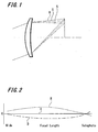
- FIG. 1 illustrates an appearance of an image formation, in which rays of R, G, and B passed through a lens have focal positions varied in the direction perpendicular to an optical axis.
- a degree of displacement varies depending on characteristics of a lens and a zoom position, focus position and iris condition of an image capture apparatus using such lens.
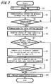
- FIG. 2 shows an example representing a relationship between an amount of displacement of focal positions and the zoom setting.
- the vertical axis represents an amount of displacement in focal positions and the horizontal axis represents a zoom position (from wide to telescopic views).
- the focal position of G is used as a standard. Displacements of R and B are relatively represented with reference to G.
- a video camera used for shooting television programs may require a decrease in lateral chromatic aberration because it appears as a varied registration error.
- a lens material such as fluorite which shows stable optical performance without a difference in focal lengths over the broad range of wavelengths may be used for reducing the lateral chromatic aberration, for example.
- the reduction of aberration can also be expected by the use of a combination of lenses made of materials with different refractive indexes.
- fluorite is expensive. If fluorite is used, production costs may increase as a result. Similarly, in the case of combining a plurality of lenses, production costs may increase all the same.
- a technique has been devised to correct the lateral chromatic aberration by carrying out image signal processing on digital image data captured by an image capture apparatus.
- FIGS. 3A and 3B are graphical representations respectively showing an example of a light intensity ratio of the center to the periphery of the lens under each state of normal or wide angle of view.
- the light intensities (%) are plotted on the vertical axis and the locations from the center to the corner are plotted on the horizontal axis.
- two curves are represented. A lower curve is one obtained when the iris position is set to full-aperture and an upper curve is one obtained when the iris is narrowed.
- FIG. 3A is a graphical representation of a light intensity ratio of the center to the corner of the screen when the zoom is set to a wide angle.
- FIG. 3B is a graphical representation of a light intensity ratio of the center to corner of the screen when the zoom is set to normal.
- the common phenomenon in both FIGS. 3A and 3B is that the larger the iris opens the more the light intensity of the periphery (corners) of the screen drops compared with that of the center thereof.
- the reduction of the light intensity also varies with the state of the zoom position.
- the light falloff at edges can be prevented by enlarging the diameter of the lens.
- the light falloff at edges may be corrected by carrying out image signal processing on digital data obtained by shooting.
- JP 2000-3437 A discloses the correction of a decrease in image quality attributed to the aberration of a lens with respect to digital image data obtained by a digital camera.
- Video cameras in particular, used for shooting television programs and so on typically use interchangeable lenses.
- an image capture apparatus such as a video camera using an interchangeable lens, may need to prepare correction data for each model of the lens if the lateral chromatic aberration is corrected and the light falloff at edges is corrected.
- the correction should be carried out in real time.
- a technique for the real-time correction has not been devised for a video camera using such interchangeable lens.
- an image capture apparatus including a lens, such as an interchangeable lens, detachably mounted thereto.
- Embodiments of the invention provide an image capture apparatus suitably applied to a video camera or the like, a lens apparatus to be mounted on such an image capture apparatus, and a method for correcting image quality.
- an image capture apparatus on which a lens apparatus is detachably mounted.
- the lens apparatus stores correction information for lateral chromatic aberration and correction information for light falloff at edges, which are characteristic information about the aberration of the lens.
- the image capture apparatus communicates with the lens apparatus when the image capture apparatus is powered on, when the lens apparatus is attached to the image capture apparatus for the first time, or when the lens apparatus is replaced.
- the image capture apparatus receives the correction information for lateral chromatic aberration and the correction information for light falloff at edges stored in the lens apparatus. Subsequently, the received correction information is used to correct both the lateral chromatic aberration and the correct light falloff at edges, which are attributed to the lens.
- the image capture apparatus and the lens apparatus are configured as described above, when the image capture apparatus is powered on, when the lens apparatus is attached to the image capture apparatus for the first time, or when the lens apparatus is replaced, correction information for lateral chromatic aberration and correction information for light falloff at edges can be transmitted to the image capture apparatus. Thus, at the time of correction, the required information is read out in the image capture apparatus in each case and a real-time correction can be then carried out.
- an image capture apparatus on which a lens apparatus is detachably mounted.
- the lens apparatus stores correction information for lateral chromatic aberration and correction information for light falloff at edges, which are characteristic information about aberration of the lens.
- the image capture apparatus communicates with the lens apparatus to read out the correction information for lateral chromatic aberration and the correction information for light falloff at edges which are stored in the lens apparatus at timing of once a field (indicating vertical scanning of a video signal, e.g., 1/60 sec). Then, the read-out correction information is used to carry out the correction of lateral chromatic aberration and the correction of light falloff at edges, which are attributed to the lens.
- the correction information for lateral chromatic aberration and the correction information for light falloff at edges are transmitted from the lens apparatus in each case at timing of once a field. Therefore, the read-out correction information about the lens is used in real-time correction.
- an image capture apparatus on which a lens, such as an interchangeable lens, is detachably mounted carries out the real-time correction of image degradation attributed to the lens.
- the lens unit 1 shown in FIG. 4 includes a lens group 10, a lens drive mechanism 11, a lens drive unit 12, an iris 13, an iris drive unit 14, a position detector 15, a lens control unit 16, and a lens memory 17. That is, the lens group 10 includes an image-capture lens, a focus lens for focusing a subject image on an imaging area, and a zoom lens for changing a focal length by changing the distance between the lenses (each of the lenses not shown in the figure).
- the lens drive mechanism 11 shifts the position of each lens of the lens group 10 in the optical axis direction.
- the lens drive unit 12 controls the movement of the lens drive mechanism 11.
- the iris 13 adjusts the light intensity of light incident on the lens group 10.
- the iris drive unit 14 actuates the iris 13.
- the position detector 15 detects the position of each lens of the lens group 10.
- the lens control unit 16 controls the actuation of each lens.
- the lens memory 17 stores the position of each lens detected by the position detector 15, and so on.
- optical correction data such as correction data for lateral chromatic aberration and correction data for light falloff at edges, can be stored in the lens memory 17 for each kind of lens, while the information can be read out by the camera unit 2 as necessary to carry out optical correction.
- Optical correction data is unique to each lens and the details of which will be described later.
- Iris-position information, focus-position information, and zoom-position information which are the information necessary for the correction of the lateral chromatic aberration and the light falloff at edges can be detected by the position detector 15 at any time and stored as detected signals in the lens memory 17, respectively.
- the lens control unit 16 includes a lens CPU and so on and generates control signals in response to commands from a control unit of the camera unit 2 as described later, followed by supplying the control signals to the lens drive unit 12 and the iris drive unit 14. In addition, the lens control unit 16 responds to requests of transferring various kinds of information (e.g., information about zoom position, focus position, and iris position) and then transfers information corresponding to the requests to the camera unit 2 through the communication line 30.
- the lens drive unit 12 is a drive circuit for driving the lens drive mechanism 11.
- the lens drive unit 12 is controlled upon receiving a control signal input from the lens control unit 16.
- the iris drive unit 14 is a drive circuit for providing an iris drive mechanism (not shown) with a control signal, where the iris drive mechanism is provided for opening and closing the iris.
- the iris drive unit 14 is also driven under the control of the lens control unit 16.
- the camera unit 2 includes the lens mount 20, an image capture device 21, a signal processor 22, a control unit 23, a memory 24, and so on.
- the lens mount 20 is a junction of the camera unit 2 with the lens unit 1.
- the image capture device 21 is provided for generating a captured image signal by photoelectrical conversion of the captured image light of the subject incident through the lens group 10 of the lens unit 1.
- the signal processor 22 is provided for carrying out the image signal processing on the captured image signal output from the image capture device 21.
- the control unit 23 is provided for controlling each part of the camera unit 2.
- the memory 24 is provided for storing the captured image signal subjected to the image processing in the signal processor 22, and so on.
- Subject light incident through the lens group 10 of the lens unit 1 forms an image in a light-receiving surface (not shown) of the image capture device 21 and then photo-electrically converted into a captured image signal.
- the captured image signal output from the image capture device 21 is subjected to the removal of a reset noise and the adjustment of a signal level in an analog signal processor (not shown).
- the captured image signal is converted into a digital signal in an analog/digital converter (not shown).
- the captured image signal which has been converted into the digital signal in the analog/digital converter, is then supplied to the signal processor 22. After that, the signal processor 22 carries out the image signal processing on the captured image signal.
- the signal processor 22 carries out knee correction that compresses a predetermined level or more of the image signal, ⁇ correction for correcting the level of the image signal based on a predetermined ⁇ curve, white-clip processing for adjusting the signal level of an image signal within a predetermined range and so on.
- knee correction that compresses a predetermined level or more of the image signal
- ⁇ correction for correcting the level of the image signal based on a predetermined ⁇ curve
- white-clip processing for adjusting the signal level of an image signal within a predetermined range and so on.
- the correction of lateral chromatic aberration and the collection of light falloff at edges may also be carried out.
- the signal processor 22 of the camera unit 2 carries out the correction of lateral chromatic aberration and the correction of light falloff at edges on the basis of optical correction data stored in the lens memory 17 of the lens unit 1.
- the optical correction data stored in the lens memory 17 is arranged so as to be read into the memory 24 of the camera unit 2 when the correction is carried out in the signal processor 22.
- the reading of the data may be carried out as a part of the initialization process when the video camera 100 is powered on, the lens unit 1 is attached on the camera unit 2 for the first time, or the lens unit 1 is replaced. Alternatively, the reading may be carried out after inquiring the data of the lens unit side every time the correction is carried out. In any case, the camera unit 2 acquires the optical correction data retained in the lens unit by the communication through the communication line 30.
- the optical correction data can be represented by a general polynomial of degree n.
- n the number of coefficients thereof is four ("n + 1").
- the lateral chromatic aberration is represented by an amount of displacement (i.e., the shift of R or B with reference to G)
- the optical correction data is calculated for each of R-G and R-B.
- the correction equation is expressed by 3-degree polynomials.
- the correction equation may be expressed a polygonal of degree n, for example one of degree 4, 5, or more.
- FIG. 5A illustrates an example of the correction data structure of lateral chromatic aberration.
- Members of the structure include eight different coefficients (A to D and A' to D') of the correction data for lateral chromatic aberration.
- FIG. 5B illustrates an example of the correction data structure of light falloff at edges.
- Members of the structure include four different coefficients (A to D) of the correction data of light falloff at edges.
- Each of the degree of the lateral chromatic aberration and the degree of the light falloff at edges varies with an iris position, a focus position, and a zoom position.
- a data array is provided as a three-dimensional array of [iris position], [focus position], and [zoom position].
- each position of the iris, each position of the focus, and each position of the zoom are applied to the structural members in the array.
- the iris position has two types of "full-aperture” and "F4"; the focus position has four types of “INF (infinity)", “3 m”, “1.5 m”, and “0.8 m”, and the zoom position has ten types of "Wide”, “1.4 x”, “1.8 x”, “2.5 x”, “3.6 x”, “4.6 x”, “6.2 x”, “8.4 x”, “9.8 x", and “Tele”.
- each value may be assigned in order to the members of the structure represented by IRIS [0] to [xx], FOCUS [0] to [yy], ZOOM [0] to [zz], and so on.
- FIG. 6 shows an example of the configuration of the three-dimensional array.
- FIG. 6 is an example of the configuration of the correction data for lateral chromatic aberration, where a three-dimensional array of [iris position], [focus position], and [zoom position] is represented in matrix.
- FIG. 6 represents optical correction data at the whole zoom positions (ZOOM [0] to [xx]) when the iris position is Full-aperture (IRIS [0]) and the focus position is Infinity (FOCUS [0]).
- FIG. 6 also represents optical correction data when the iris position is Full-aperture (IRIS [0]), the focus position is 1.4 x (FOCUS [1]), and the zoom position is Wide (ZOOM [0]).
- the optical correction data is prepared as a table of the three-dimensional array to allow every combination of the iris position, the focus position, and the zoom position to be specified in the array. For example, if the correction data when the iris position is F4, the focus position is 1.5 m, and the zoom position is 2.5 x is acquired, the intended optical correction data can be obtained by specifying [2nd iris (IRIS [1])], [3rd Focus (FOCUS [2]), and [4th Zoom (ZOOM [3])].
- FIG. 7 illustrates an example of the process when the lens unit 1 is attached to the camera unit 2 for the first time. Whether the lens unit 1 is the first lens to be attached may be determined such that the camera unit 2 confirms the lens name of the lens unit 1 when the lens unit 1 is attached to the camera unit 2.
- Step S1 when the video camera 100 is powered on (Step S1), the process of communication connection between the lens unit 1 and the camera unit 2 is carried out (Step S2). The details of such a process of communication connection between the lens unit 1 and the camera unit 2 will be described later.
- Step S3 whether the communication is established at the process of communication connection between the lens unit 1 and the camera unit 2 is determined (Step S3). During the period of no communication established, the process of communication connection at Step S2 is carried out.
- the communication for data initialization is carried out between the lens unit 1 and the camera unit 2 (Step S4).
- the lens unit 1 may transmit the characteristic information of the lens, such as the lens name and manufacturer name, to the camera unit 2. Alternatively, data requiring initialization may be transmitted and received between the lens unit 1 and the camera unit 2.
- the camera unit 2 obtains the status of the lens retaining the optical correction data from the lens unit 1 (Step S5) and then determines whether the lens unit 1 is the lens retaining the optical correction data (Step S6). If it is determined that the lens unit 1 is the lens not retaining the optical correction data, then the process proceeds to Step S10 and a normal communication process is carried out. The details of the process of determining whether the lens unit 1 is the lens retaining the optical correction data will be described later. If it is determined that the lens unit 1 is the lens retaining the optical correction data, then the control unit 23 of the camera unit 2 transmits a command that requests the acquisition of the optical correction data to the lens unit 1 (Step S7).
- Step S8 optical correction data stored in the lens memory 17 is transmitted to the camera unit side.
- Step S9 it is determined whether the initialization process is completed. The initialization process is continued until the completion of the initialization process is determined. If it is determined that the initialization process is completed, then the normal communication process is carried out (Step S10).
- the flowchart of FIG. 7 represents an exemplified process for obtaining the optical correction data when power is on.
- the same process will be conducted.
- the data received and transmitted between the camera unit 2 and the lens unit 1 contains command (1 byte), function (1 byte), function data (0 to 15 bytes, variable in length), and checksum (1 byte).
- Four bits at the top of 1 byte of the command represents the main class of the command.
- the bits "0000” corresponds to a camera command
- "1111” corresponds to a lens-maker user command
- "0001 to 1110" corresponds to reservation.
- four bits at the end of 1 byte of the command represents the data length of function data described later.
- the function is a code that indicates data actually exchanged between the lens unit 1 and the camera unit 2, such as the request and response of F number and the request and response of serial number, and represented by "01" or the like.
- the checksum is provided for inspecting whether an error occurs in data transmitted between the lens unit 1 and the camera unit 2.
- the checksum is provided with a value that gives a total value of 0 (zero) from the command to the checksum.
- the total of data row sent from the receiving side is calculated. There is no error or lack of data in the received data row when the total is 0 (zero).
- the determination of whether the lens unit 1 is a lens that retains optical correction data can be carried out by obtaining and securing a flag on the side of the camera unit 2.
- the flag indicates whether the lens unit 1 is a lens that retains optical correction data.
- the camera unit 2 transmits a command with the frame construction as shown in FIG. 8 to the lens unit 1 for making an inquiry about the flag. If there is no response from the lens unit 1, then it is determined that the lens does not retain the optical correction data.
- Step S5 the acquisition of a lens status of retaining the optical correction data at the camera unit 2 from the lens unit 1
- Step S6 the details of the process of the determination
- FIG. 9 shows an exchange of data between the camera unit 2 and the lens unit 1 and an exemplified construction of the data to be transmitted and received.
- the correction data for lateral chromatic aberration and light falloff at edges are used as the optical correction data.
- a coefficient for the correction of lateral chromatic aberration or light falloff at edges varies with the iris position, the focus position, and the zoom position. The number of sections of these positions varies with the kind of the lens.
- the camera unit 2 reads an optical correction data table stored in the lens memory 17 of the lens unit 1, there is a need of obtaining the number of kinds of the iris position, the focus position, and zoom position (i.e., the number of partitions), respectively. In addition, it may be necessary to obtain on what kind of numerical value the partitions are bordered.
- the value on the boundary between partitions is expressed by an actual value, that is, F number at a position represented by "full-aperture” or "F4" when, for example, there are two different kinds of iris position, "full-aperture” and "F4".
- the focus position is represented by a focal distance
- the zoom position is represented by the magnification of the zoom setting.
- FIG. 9 illustrates a process example when the lens unit 1 retains the table for the correction data for lateral chromatic aberration as shown in FIG. 6.
- the camera unit 2 inquires of the lens unit 1 about the number of types of the iris position, the focus position, and the zoom position in order and then forms the format of a correction data table based on a response from the lens unit 1.
- the camera unit 2 inquires about "ordinal iris position in a sequence”, “ordinal focus position in a sequence”, and “ordinal zoom position in a sequence” and obtains the responses thereof, thereby acquiring all correction data stored in the lens unit 1.
- the camera unit 2 inquires of the lens unit 1 about the iris position, the focus position, and the zoom position in this order has been descried.
- any of other orders of inquiries may be employed.
- the camera unit 2 transmits a command inquiring about the number of partitions of the iris position to the lens unit 1 (1).
- the command structure at this time is shown on the right side of a sequence diagram.
- "0001" is used as the command, for example. However, actually, it may use any of other numerical values which have not been assigned in reservation codes of "0001 to 1110".
- "AA" is the function used for an acquisition request for the number of partitions of the iris position, so that "AA” is described in the function.
- the function data is set to "0".
- the lens unit 1 Upon receiving the command from the camera unit 2, the lens unit 1 responds to the number of partitions of the iris and the value on the boundary between the partitions (2). As described above, in the lens unit 1, the number of partitions is 2. Since the values on the boundaries between the partitions are 1.6 (the value of "full-aperture") and 4.1 (the value of F4), respectively, the information is described in the function data and transmitted to the camera unit 2. In this example, the number of partitions is described on the first two bytes (strictly the latter one of these two bytes) of the function data. The value of the boundary of the division is described on the third byte or later. Therefore, in the data transmitted from the lens unit 1 to the camera unit 2, the function is the same "AA" as that of the request command.
- the values of the partition boundaries are described on the second, third, and fourth bytes, which correspond to the numbers of partitions of the iris.
- the camera unit 2 requests both the number of partitions and the number of partition boundaries of the focus (3). If “BB” is used as the function when requiring the number of partitions of the focus, “BB” is placed in the function while there is nothing in the function data (i.e., "0") and then transmitted to the lens unit 1. On the other hand, the lens unit 1 responds to the camera unit 2 by describing "BB” in the function, "4" (the number of partitions) on the first two bytes of the function data, and the value of partition boundary on the third byte or later of the function data (4).
- both the number of partitions and the number of partition boundaries of zoom setting are required (5).
- "CC” is used as the function set when requiring the number of partitions of the zoom
- "CC” is placed in the function while there is nothing in the function data (i.e., "0") and then transmitted to the lens unit 1.
- the lens unit 1 responds to the camera unit 2 by describing "CC” in the function, "10” (the number of partitions) on the first two bytes of the function data, and the value of partition boundary on the third byte or later of the function data (6).
- the format of the optical correction data table is formed on the camera unit 2. If the format of the table is formed, then the optical correction data, which is the actual value stored in the table, is acquired.
- DD lateral chromatic aberration
- the lens unit 1 Upon receiving a request command for acquiring the lateral chromatic aberration correction data transmitted from the camera unit 2, then the lens unit 1 reads out the lateral chromatic aberration correction data in a sequence designated in the command from the lens memory 17. The read data is transmitted to the camera unit 2 (8).
- ID which represents the ordinal position of the response in a sequence
- the lateral chromatic aberration correction data may require data in R-B in addition to the data in R-G. Therefore, also in R-B, the acquisition of correction data is carried out by the same procedures as those described above.
- DD is described in the function of the response data and "1" is assigned as a response ID to the first two bytes of the function data.
- sequence positions of the optical correction data are described on the third byte to the fifth byte of the function data.
- a value representing the ordinal iris position in a sequence is placed in the third byte.
- a value representing the ordinal focus position in a sequence is placed in the fourth byte.
- a value representing the ordinal zoom position in a sequence is placed in the fifth byte.
- a coefficient of the actual correction data is described on the sixth byte or later. Two bytes are used for representing one coefficient.
- the correction data is represented by a polynomial cubic equation
- the first coefficient "A” is described on the sixth byte and the seventh byte
- the next coefficient "B” is described on the eighth byte and the ninth byte
- the next coefficient "C” is described on the tenth byte and the eleventh byte
- the last coefficient D is described on twelfth byte and the thirteenth byte.
- the request and response of correction data is carried out the number of times corresponding to the result of the following multiplication:
- the optical correction data table stored in the lens memory 17 of the lens unit 1 is read out by the memory 24 of the camera unit 2.
- the procedures for acquiring the light falloff at edges correction data can also be performed in a manner similar to one described above.
- coefficients based on the iris position, the focus position, and the zoom position are read from the optical correlation data table previously read in its memory 24, followed by carrying out correction using the read coefficient.
- the lateral chromatic aberration correction data and the light falloff at edges correction data are stored in the lens unit 1 in advance. Then, the camera unit 2 reads the correction data tables stored in the lens unit 1 through communication. The camera unit 2 carries out optical correction based on the read correction data. Therefore, the optical correction can be carried out in conformity to the characteristics of the lens in the case where various kinds of interchangeable lens having different optical characteristics are used.
- the optical correction data table is read into the memory 24 of the camera unit 2 from the lens unit 1 when an initialization communication is carried out between the lens unit 1 and the camera unit 2. Therefore, any required correction data can be read from the optical correction data table stored in the memory 24 at the time of performing an optical correction in the camera unit 2. Consequently, in the case of using an interchangeable lens, the correction can be carried out in real time while shooting a moving image.
- the corrections of lateral chromatic aberration and light falloff at edges are designed to be carried out by image signal processing on the camera unit 2. Therefore, there is no need of using an expensive lens and the production costs can be reduced.
- the optical correction data stored in the lens unit 1 is acquired entirely as a data table when the video camera 100 is powered on, when the lens unit 1 is connected to the camera unit 2 for the first time, or when the lens unit 1 is replaced.
- the camera unit 2 may only acquire the required optical correction data from the lens unit 1.
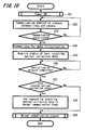
- the acquisition of optical correction data by the camera unit 2 is carried out at timing of once a field. The process example of this case will be described with reference to the flowchart of FIG. 10 and the sequence diagram and the data configuration diagram of FIG. 11.
- timing is not limited to once a field, but may be once for two fields or other periods.
- Step S31 when the video camera 100 is powered on (Step S31), the process of communication connection between the lens unit 1 and the camera unit 2 is carried out (Step S32). Subsequently, whether a communication between the lens unit 1 and the camera unit 2 is established by the process of communication connection is determined (Step S33). While no communication being established, the process of communication connection at Step S32 is carried out. When the establishment of the communication is determined, communication for data initialization is carried out between the lens unit 1 and the camera unit 2 (Step S34).
- Step S35 if the lens unit 1 acquires the status of the lens that retains optical correction data (Step S35), whether the initialization process is completed is determined (Step S36). The initialization process is successively carried out until it is determined that the initialization process is completed. If it is determined that the initialization process is completed, then it is determined whether the lens unit 1 is a lens retaining optical correction data on the basis of the status acquired in Step S35 (Step S37).
- step S39 If it is determined that the lens unit 1 is a lens not retaining any optical correction data, the process proceeds to step S39 to carry out a normal communication process. If it is determined that the lens unit 1 is a lens that uses the optical correction data, then a command for requesting the acquisition of optical correction data is added to the normal communication items (Step S38), followed by carrying out the normal communication process (Step S39).
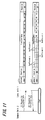
- FIG. 11 illustrates a process example at the time of acquiring the lateral chromatic aberration correction data.
- a command which requires lateral chromatic aberration correction data transmission, is transmitted from the camera unit 2 to the lens unit 1 (1).
- DD which means an acquisition request for lateral chromatic aberration correction data (R-G)
- R-G lateral chromatic aberration correction data
- the lens unit 1 which has received the command from the camera unit 2, makes a determination about the iris position, the focus position, and the zoom position at that time and then reads out the corresponding correction data from the lens memory 17, followed by responding to the camera unit 2 (2).
- "DD" is described in the function of the response data.
- the coefficient of the lateral chromatic aberration correction data is described on the function data. Two bytes are used for representing one coefficient.
- the first coefficient "A” is described on the first byte and the second byte
- the next coefficient "B” is described on the third byte and the fourth byte
- the next coefficient "C” is described on the fifth byte and the sixth byte
- the last coefficient D is described on the seventh byte and the eighth byte.
- the lens memory 17 of the lens unit I is requested to transmit optical correction data and a correction is carried out on the camera unit 2 using a coefficient contained in the response data from the lens memory 17 of the lens 1.
- the optical correction can be carried out in real time while shooting a moving image.
- the aforementioned embodiment stores optical correction data for each kind of lens.
- the optical correction data based on the individual difference of the lens may be stored.
Landscapes
- Engineering & Computer Science (AREA)
- Multimedia (AREA)
- Signal Processing (AREA)
- Studio Devices (AREA)
- Structure And Mechanism Of Cameras (AREA)
- Exposure Control For Cameras (AREA)
Abstract
Description
- The present invention relates to a lens apparatus for detachable mounting on an image capture apparatus, an image capture apparatus and a method for correcting image degradation.
- In general, optical lenses may cause a phenomenon called aberration, which causes an unfavorable colored portion, an out of focus, and an image distortion when an image is formed. For example, one kind of aberration is known as a lateral chromatic aberration (chromatic aberration of magnification) by which a blur occurs on the boundary area of a subject image. The lateral chromatic aberration is caused such that, when an image is formed, rays of red (R), green (G), and blue (B) passed through a lens have focal positions varied in the direction perpendicular to an optical axis depending on wavelengths. FIG. 1 illustrates an appearance of an image formation, in which rays of R, G, and B passed through a lens have focal positions varied in the direction perpendicular to an optical axis. A degree of displacement varies depending on characteristics of a lens and a zoom position, focus position and iris condition of an image capture apparatus using such lens. FIG. 2 shows an example representing a relationship between an amount of displacement of focal positions and the zoom setting.
- In FIG. 2, the vertical axis represents an amount of displacement in focal positions and the horizontal axis represents a zoom position (from wide to telescopic views). In FIG. 2, the focal position of G is used as a standard. Displacements of R and B are relatively represented with reference to G. In particular, a video camera used for shooting television programs may require a decrease in lateral chromatic aberration because it appears as a varied registration error.
- A lens material such as fluorite which shows stable optical performance without a difference in focal lengths over the broad range of wavelengths may be used for reducing the lateral chromatic aberration, for example. On the other hand, the reduction of aberration can also be expected by the use of a combination of lenses made of materials with different refractive indexes. However, fluorite is expensive. If fluorite is used, production costs may increase as a result. Similarly, in the case of combining a plurality of lenses, production costs may increase all the same. Thus, a technique has been devised to correct the lateral chromatic aberration by carrying out image signal processing on digital image data captured by an image capture apparatus.
- In addition to the aberration, a phenomenon of light falloff at edges, which causes an image degradation attributed to characteristics of a lens, has also been known. The "light falloff at edges" is a phenomenon in which an amount of light at the edges of a screen falls compared with the center thereof. Such a phenomenon may be caused by obstructing part of peripheral rays with a lens barrel. The degree of light falloff varies extensively depending on the zoom setting and focus and iris conditions of an image capture apparatus using the lens. FIGS. 3A and 3B are graphical representations respectively showing an example of a light intensity ratio of the center to the periphery of the lens under each state of normal or wide angle of view. In FIGS. 3A and 3B, the light intensities (%) are plotted on the vertical axis and the locations from the center to the corner are plotted on the horizontal axis. In each figure, two curves are represented. A lower curve is one obtained when the iris position is set to full-aperture and an upper curve is one obtained when the iris is narrowed.
- FIG. 3A is a graphical representation of a light intensity ratio of the center to the corner of the screen when the zoom is set to a wide angle. FIG. 3B is a graphical representation of a light intensity ratio of the center to corner of the screen when the zoom is set to normal. The common phenomenon in both FIGS. 3A and 3B is that the larger the iris opens the more the light intensity of the periphery (corners) of the screen drops compared with that of the center thereof. In addition, as shown in FIGS. 3A and 3B, the reduction of the light intensity also varies with the state of the zoom position. The light falloff at edges can be prevented by enlarging the diameter of the lens. Alternatively, similarly to the correction to the lateral chromatic aberration, the light falloff at edges may be corrected by carrying out image signal processing on digital data obtained by shooting.
-
Japanese Unexamined Patent Application Publication No. 2000-3437 JP 2000-3437 A - Video cameras, in particular, used for shooting television programs and so on typically use interchangeable lenses. However, an image capture apparatus, such as a video camera using an interchangeable lens, may need to prepare correction data for each model of the lens if the lateral chromatic aberration is corrected and the light falloff at edges is corrected. In addition, since moving images are captured, the correction should be carried out in real time. However, a technique for the real-time correction has not been devised for a video camera using such interchangeable lens.
- It is desirable to correct an image degradation attributed to aberration of a lens in real time in an image capture apparatus including a lens, such as an interchangeable lens, detachably mounted thereto.
- Various respective aspects and features of the invention are defined in the appended claims. Combinations of features from the dependent claims may be combined with features of the independent claims as appropriate and not merely as explicitly set out in the claims.
- Embodiments of the invention provide an image capture apparatus suitably applied to a video camera or the like, a lens apparatus to be mounted on such an image capture apparatus, and a method for correcting image quality.
- According to an embodiment of the present invention, there is provided an image capture apparatus on which a lens apparatus is detachably mounted. In the case of correcting the aberration of a lens, the lens apparatus stores correction information for lateral chromatic aberration and correction information for light falloff at edges, which are characteristic information about the aberration of the lens. The image capture apparatus communicates with the lens apparatus when the image capture apparatus is powered on, when the lens apparatus is attached to the image capture apparatus for the first time, or when the lens apparatus is replaced. As a result, the image capture apparatus receives the correction information for lateral chromatic aberration and the correction information for light falloff at edges stored in the lens apparatus. Subsequently, the received correction information is used to correct both the lateral chromatic aberration and the correct light falloff at edges, which are attributed to the lens.
- Since the image capture apparatus and the lens apparatus are configured as described above, when the image capture apparatus is powered on, when the lens apparatus is attached to the image capture apparatus for the first time, or when the lens apparatus is replaced, correction information for lateral chromatic aberration and correction information for light falloff at edges can be transmitted to the image capture apparatus. Thus, at the time of correction, the required information is read out in the image capture apparatus in each case and a real-time correction can be then carried out.
- According to another embodiment of the present invention, there is provided an image capture apparatus on which a lens apparatus is detachably mounted. The lens apparatus stores correction information for lateral chromatic aberration and correction information for light falloff at edges, which are characteristic information about aberration of the lens. The image capture apparatus communicates with the lens apparatus to read out the correction information for lateral chromatic aberration and the correction information for light falloff at edges which are stored in the lens apparatus at timing of once a field (indicating vertical scanning of a video signal, e.g., 1/60 sec). Then, the read-out correction information is used to carry out the correction of lateral chromatic aberration and the correction of light falloff at edges, which are attributed to the lens.
- Since the image capture apparatus and the lens apparatus are configured as described above, the correction information for lateral chromatic aberration and the correction information for light falloff at edges are transmitted from the lens apparatus in each case at timing of once a field. Therefore, the read-out correction information about the lens is used in real-time correction.
- According to embodiments of the present invention, an image capture apparatus on which a lens, such as an interchangeable lens, is detachably mounted carries out the real-time correction of image degradation attributed to the lens.
- Embodiments of the invention will now be described with reference to the accompanying drawings, throughout which like parts are referred to by like references, and in which:
- FIG. 1 is a graphical representation indicating an amount of displacement in focal positions of respective colors on lateral chromatic aberration.
- FIG. 2 is a graphical representation of the relationship between a lateral chromatic aberration and a focal length.
- FIGS. 3A and 3B are graphical representations of a light intensity ratio of the center to the periphery of the lens under each state of normal and wide field of view. FIG. 4 is a block diagram illustrating an exemplified inner configuration of a video camera according to an embodiment of the present invention.
- FIGS. 5A and 5B are explanatory diagrams illustrating an exemplified configuration of coefficient data of optical correction data according to an embodiment of the present invention.
- FIG. 6 is an explanatory diagram illustrating an exemplified configuration of optical correction data according to an embodiment of the present invention.
- FIG. 7 is a flowchart illustrating a process example for acquiring optical correction data during an initialization process according to an embodiment of the present invention.
- FIG. 8 is an explanatory diagram illustrating an example of data formant at the time of communication according to an embodiment of the present invention.
- FIG. 9 is an explanatory diagram illustrating a process example for acquiring optical correction data during an initialization process according to an embodiment of the present invention.
- FIG. 10 is a flowchart illustrating a process example for periodically acquiring optical correction data according to another embodiment of the present invention.
- FIG. 11 is an explanatory diagram illustrating a process example for periodically acquiring optical correction data according to another embodiment of the present invention.
- Hereinafter, embodiments of the present invention will be described with reference to FIGS. 4 to 11.
- FIG. 4 shows an exemplified configuration of a video camera as an example of an image capture apparatus according to a first embodiment of the present invention. As shown in FIG. 1, a
video camera 100 includes alens unit 1 and acamera unit 2. Thelens unit 1 is an interchangeable lens and designed to be detachably mounted on thecamera unit 2 through alens mount 20. Thecamera unit 2 provides thelens unit 1 with instructions or the like for changing the zoom setting and the focal position. Such a data communication between thelens unit 1 and thecamera unit 2 can be carried out through acommunication line 30 in a state that thelens unit 1 is being attached on thecamera unit 2. - The
lens unit 1 shown in FIG. 4 includes alens group 10, a lens drive mechanism 11, alens drive unit 12, aniris 13, aniris drive unit 14, aposition detector 15, alens control unit 16, and alens memory 17. That is, thelens group 10 includes an image-capture lens, a focus lens for focusing a subject image on an imaging area, and a zoom lens for changing a focal length by changing the distance between the lenses (each of the lenses not shown in the figure). The lens drive mechanism 11 shifts the position of each lens of thelens group 10 in the optical axis direction. Thelens drive unit 12 controls the movement of the lens drive mechanism 11. Theiris 13 adjusts the light intensity of light incident on thelens group 10. Theiris drive unit 14 actuates theiris 13. Theposition detector 15 detects the position of each lens of thelens group 10. Thelens control unit 16 controls the actuation of each lens. Thelens memory 17 stores the position of each lens detected by theposition detector 15, and so on. In this embodiment, optical correction data, such as correction data for lateral chromatic aberration and correction data for light falloff at edges, can be stored in thelens memory 17 for each kind of lens, while the information can be read out by thecamera unit 2 as necessary to carry out optical correction. Optical correction data is unique to each lens and the details of which will be described later. - Iris-position information, focus-position information, and zoom-position information, which are the information necessary for the correction of the lateral chromatic aberration and the light falloff at edges can be detected by the
position detector 15 at any time and stored as detected signals in thelens memory 17, respectively. - The
lens control unit 16 includes a lens CPU and so on and generates control signals in response to commands from a control unit of thecamera unit 2 as described later, followed by supplying the control signals to thelens drive unit 12 and theiris drive unit 14. In addition, thelens control unit 16 responds to requests of transferring various kinds of information (e.g., information about zoom position, focus position, and iris position) and then transfers information corresponding to the requests to thecamera unit 2 through thecommunication line 30. Thelens drive unit 12 is a drive circuit for driving the lens drive mechanism 11. Thelens drive unit 12 is controlled upon receiving a control signal input from thelens control unit 16. Theiris drive unit 14 is a drive circuit for providing an iris drive mechanism (not shown) with a control signal, where the iris drive mechanism is provided for opening and closing the iris. Theiris drive unit 14 is also driven under the control of thelens control unit 16. - The
camera unit 2 includes thelens mount 20, animage capture device 21, asignal processor 22, acontrol unit 23, amemory 24, and so on. Thelens mount 20 is a junction of thecamera unit 2 with thelens unit 1. Theimage capture device 21 is provided for generating a captured image signal by photoelectrical conversion of the captured image light of the subject incident through thelens group 10 of thelens unit 1. Thesignal processor 22 is provided for carrying out the image signal processing on the captured image signal output from theimage capture device 21. Thecontrol unit 23 is provided for controlling each part of thecamera unit 2. Thememory 24 is provided for storing the captured image signal subjected to the image processing in thesignal processor 22, and so on. - Subject light incident through the
lens group 10 of thelens unit 1 forms an image in a light-receiving surface (not shown) of theimage capture device 21 and then photo-electrically converted into a captured image signal. Subsequently, the captured image signal output from theimage capture device 21 is subjected to the removal of a reset noise and the adjustment of a signal level in an analog signal processor (not shown). The captured image signal is converted into a digital signal in an analog/digital converter (not shown). The captured image signal, which has been converted into the digital signal in the analog/digital converter, is then supplied to thesignal processor 22. After that, thesignal processor 22 carries out the image signal processing on the captured image signal. Thesignal processor 22 carries out knee correction that compresses a predetermined level or more of the image signal, γ correction for correcting the level of the image signal based on a predetermined γ curve, white-clip processing for adjusting the signal level of an image signal within a predetermined range and so on. In addition, the correction of lateral chromatic aberration and the collection of light falloff at edges may also be carried out. - The
signal processor 22 of thecamera unit 2 carries out the correction of lateral chromatic aberration and the correction of light falloff at edges on the basis of optical correction data stored in thelens memory 17 of thelens unit 1. The optical correction data stored in thelens memory 17 is arranged so as to be read into thememory 24 of thecamera unit 2 when the correction is carried out in thesignal processor 22. The reading of the data may be carried out as a part of the initialization process when thevideo camera 100 is powered on, thelens unit 1 is attached on thecamera unit 2 for the first time, or thelens unit 1 is replaced. Alternatively, the reading may be carried out after inquiring the data of the lens unit side every time the correction is carried out. In any case, thecamera unit 2 acquires the optical correction data retained in the lens unit by the communication through thecommunication line 30. - Next, a method of calculating optical correction data and a method of preparing a data table will be described. The optical correction data can be represented by a general polynomial of degree n. For example, in the case of expressing with a polynomial of
degree 3, the number of coefficients thereof is four ("n + 1"). As the lateral chromatic aberration is represented by an amount of displacement (i.e., the shift of R or B with reference to G), the optical correction data is calculated for each of R-G and R-B. In the following equations, four coefficients in the 3-degree polynomial are represented by A to D, respectively:

- The correction equation of the light falloff at edges can also be obtained in the same way:

- Note that in the present embodiment, the correction equation is expressed by 3-degree polynomials. Alternatively, however, the correction equation may be expressed a polygonal of degree n, for example one of
degree - The optical correction data thus obtained may be provided in a table format as illustrated in FIGS. 5A and 5B and then stored in the
lens memory 17 as a structure. FIG. 5A illustrates an example of the correction data structure of lateral chromatic aberration. Members of the structure include eight different coefficients (A to D and A' to D') of the correction data for lateral chromatic aberration. FIG. 5B illustrates an example of the correction data structure of light falloff at edges. Members of the structure include four different coefficients (A to D) of the correction data of light falloff at edges. Each of the degree of the lateral chromatic aberration and the degree of the light falloff at edges varies with an iris position, a focus position, and a zoom position. Thus, it may be required to prepare the optical correction data corresponding to the iris position, focus position, and zoom position, respectively. Therefore, a data array is provided as a three-dimensional array of [iris position], [focus position], and [zoom position]. For representing the three-dimensional array, each position of the iris, each position of the focus, and each position of the zoom are applied to the structural members in the array. - For example, the iris position has two types of "full-aperture" and "F4"; the focus position has four types of "INF (infinity)", "3 m", "1.5 m", and "0.8 m", and the zoom position has ten types of "Wide", "1.4 x", "1.8 x", "2.5 x", "3.6 x", "4.6 x", "6.2 x", "8.4 x", "9.8 x", and "Tele". In this case, each value may be assigned in order to the members of the structure represented by IRIS [0] to [xx], FOCUS [0] to [yy], ZOOM [0] to [zz], and so on. For example, in the case of the iris position, the assignment may be IRIS [0] = Full-aperture, IRIS [1] = F4, but no assignment in any of IRIS [2] to [xx].
- FIG. 6 shows an example of the configuration of the three-dimensional array. In other words, FIG. 6 is an example of the configuration of the correction data for lateral chromatic aberration, where a three-dimensional array of [iris position], [focus position], and [zoom position] is represented in matrix. FIG. 6 represents optical correction data at the whole zoom positions (ZOOM [0] to [xx]) when the iris position is Full-aperture (IRIS [0]) and the focus position is Infinity (FOCUS [0]). FIG. 6 also represents optical correction data when the iris position is Full-aperture (IRIS [0]), the focus position is 1.4 x (FOCUS [1]), and the zoom position is Wide (ZOOM [0]).
- Thus, the optical correction data is prepared as a table of the three-dimensional array to allow every combination of the iris position, the focus position, and the zoom position to be specified in the array. For example, if the correction data when the iris position is F4, the focus position is 1.5 m, and the zoom position is 2.5 x is acquired, the intended optical correction data can be obtained by specifying [2nd iris (IRIS [1])], [3rd Focus (FOCUS [2]), and [4th Zoom (ZOOM [3])].
- Next, referring to the flowchart of FIG. 7, a process example, in which the
camera unit 2 reads out the optical correction data stored in thelens memory 17 of thelens unit 1, will be described. FIG. 7 illustrates an example of the process when thelens unit 1 is attached to thecamera unit 2 for the first time. Whether thelens unit 1 is the first lens to be attached may be determined such that thecamera unit 2 confirms the lens name of thelens unit 1 when thelens unit 1 is attached to thecamera unit 2. - First, when the
video camera 100 is powered on (Step S1), the process of communication connection between thelens unit 1 and thecamera unit 2 is carried out (Step S2). The details of such a process of communication connection between thelens unit 1 and thecamera unit 2 will be described later. Subsequently, whether the communication is established at the process of communication connection between thelens unit 1 and thecamera unit 2 is determined (Step S3). During the period of no communication established, the process of communication connection at Step S2 is carried out. When it is determined that the communication is established, the communication for data initialization is carried out between thelens unit 1 and the camera unit 2 (Step S4). In the communication for data initialization, thelens unit 1 may transmit the characteristic information of the lens, such as the lens name and manufacturer name, to thecamera unit 2. Alternatively, data requiring initialization may be transmitted and received between thelens unit 1 and thecamera unit 2. - Next, the
camera unit 2 obtains the status of the lens retaining the optical correction data from the lens unit 1 (Step S5) and then determines whether thelens unit 1 is the lens retaining the optical correction data (Step S6). If it is determined that thelens unit 1 is the lens not retaining the optical correction data, then the process proceeds to Step S10 and a normal communication process is carried out. The details of the process of determining whether thelens unit 1 is the lens retaining the optical correction data will be described later. If it is determined that thelens unit 1 is the lens retaining the optical correction data, then thecontrol unit 23 of thecamera unit 2 transmits a command that requests the acquisition of the optical correction data to the lens unit 1 (Step S7). When thelens control unit 16 of thelens unit 1 receives the command transmitted from the camera unit side, then optical correction data stored in thelens memory 17 is transmitted to the camera unit side (Step S8). At the time of completing the transmission of the optical correction data, it is determined whether the initialization process is completed (Step S9). The initialization process is continued until the completion of the initialization process is determined. If it is determined that the initialization process is completed, then the normal communication process is carried out (Step S10). - Here, the flowchart of FIG. 7 represents an exemplified process for obtaining the optical correction data when power is on. In this example, in the case of replacing the
lens unit 1 with another one while power being powered on, the same process will be conducted. - Next, the details of the procedures in the respective steps described in the flowchart of FIG. 7 will be described with reference to FIGS. 8 and 9. First, referring now to FIG. 8, an example of the format of the command or response data, which can be received and transmitted between the
camera unit 2 and thelens unit 1, will be described. As shown in FIG. 8, the data received and transmitted between thecamera unit 2 and thelens unit 1 contains command (1 byte), function (1 byte), function data (0 to 15 bytes, variable in length), and checksum (1 byte). Four bits at the top of 1 byte of the command represents the main class of the command. The bits "0000" corresponds to a camera command, "1111" corresponds to a lens-maker user command, and "0001 to 1110" corresponds to reservation. In addition, four bits at the end of 1 byte of the command represents the data length of function data described later. - The function is a code that indicates data actually exchanged between the
lens unit 1 and thecamera unit 2, such as the request and response of F number and the request and response of serial number, and represented by "01" or the like. - The checksum is provided for inspecting whether an error occurs in data transmitted between the
lens unit 1 and thecamera unit 2. The checksum is provided with a value that gives a total value of 0 (zero) from the command to the checksum. The total of data row sent from the receiving side is calculated. There is no error or lack of data in the received data row when the total is 0 (zero). By having provided the checksum, it can be checked whether all data has been transmitted without fail. - Referring again to the flowchart of FIG. 7, the determination of whether the
lens unit 1 is a lens that retains optical correction data, which is carried out in Step S5, can be carried out by obtaining and securing a flag on the side of thecamera unit 2. Here, the flag indicates whether thelens unit 1 is a lens that retains optical correction data. In other words, thecamera unit 2 transmits a command with the frame construction as shown in FIG. 8 to thelens unit 1 for making an inquiry about the flag. If there is no response from thelens unit 1, then it is determined that the lens does not retain the optical correction data. - Next, the acquisition of a lens status of retaining the optical correction data at the
camera unit 2 from the lens unit 1 (Step S5) and the details of the process of the determination (Step S6) as described in FIG. 7 will be described with reference to FIG. 9. - FIG. 9 shows an exchange of data between the
camera unit 2 and thelens unit 1 and an exemplified construction of the data to be transmitted and received. In this embodiment, the correction data for lateral chromatic aberration and light falloff at edges are used as the optical correction data. A coefficient for the correction of lateral chromatic aberration or light falloff at edges varies with the iris position, the focus position, and the zoom position. The number of sections of these positions varies with the kind of the lens. When thecamera unit 2 reads an optical correction data table stored in thelens memory 17 of thelens unit 1, there is a need of obtaining the number of kinds of the iris position, the focus position, and zoom position (i.e., the number of partitions), respectively. In addition, it may be necessary to obtain on what kind of numerical value the partitions are bordered. - The value on the boundary between partitions is expressed by an actual value, that is, F number at a position represented by "full-aperture" or "F4" when, for example, there are two different kinds of iris position, "full-aperture" and "F4". Similarly, the focus position is represented by a focal distance, and the zoom position is represented by the magnification of the zoom setting.
- FIG. 9 illustrates a process example when the
lens unit 1 retains the table for the correction data for lateral chromatic aberration as shown in FIG. 6. According to the table exemplified in FIG. 6, there are two different iris positions, four different focus positions, and ten different zoom positions. First, thecamera unit 2 inquires of thelens unit 1 about the number of types of the iris position, the focus position, and the zoom position in order and then forms the format of a correction data table based on a response from thelens unit 1. Then, after constructing the format of the correction data table, thecamera unit 2 inquires about "ordinal iris position in a sequence", "ordinal focus position in a sequence", and "ordinal zoom position in a sequence" and obtains the responses thereof, thereby acquiring all correction data stored in thelens unit 1. Note that in this embodiment the case in which thecamera unit 2 inquires of thelens unit 1 about the iris position, the focus position, and the zoom position in this order has been descried. However, any of other orders of inquiries may be employed. - An explanation will be given to the sequence shown on the left side in FIG. 9. First, the
camera unit 2 transmits a command inquiring about the number of partitions of the iris position to the lens unit 1 (1). The command structure at this time is shown on the right side of a sequence diagram. "0001" is used as the command, for example. However, actually, it may use any of other numerical values which have not been assigned in reservation codes of "0001 to 1110". In this example, "AA" is the function used for an acquisition request for the number of partitions of the iris position, so that "AA" is described in the function. In addition, the function data is set to "0". - Upon receiving the command from the
camera unit 2, thelens unit 1 responds to the number of partitions of the iris and the value on the boundary between the partitions (2). As described above, in thelens unit 1, the number of partitions is 2. Since the values on the boundaries between the partitions are 1.6 (the value of "full-aperture") and 4.1 (the value of F4), respectively, the information is described in the function data and transmitted to thecamera unit 2. In this example, the number of partitions is described on the first two bytes (strictly the latter one of these two bytes) of the function data. The value of the boundary of the division is described on the third byte or later. Therefore, in the data transmitted from thelens unit 1 to thecamera unit 2, the function is the same "AA" as that of the request command. On the first two bytes of the function data, the values of the partition boundaries are described on the second, third, and fourth bytes, which correspond to the numbers of partitions of the iris. The values of the partition boundaries are assigned sequentially from [0] in such a manner that they are assigned 1.6 = IRIS [0], 4.1 = IRIS [0], and so on in order. - Subsequent to acquiring the number of partitions and the number of partition boundaries of iris, the
camera unit 2 requests both the number of partitions and the number of partition boundaries of the focus (3). If "BB" is used as the function when requiring the number of partitions of the focus, "BB" is placed in the function while there is nothing in the function data (i.e., "0") and then transmitted to thelens unit 1. On the other hand, thelens unit 1 responds to thecamera unit 2 by describing "BB" in the function, "4" (the number of partitions) on the first two bytes of the function data, and the value of partition boundary on the third byte or later of the function data (4). - Subsequent to acquiring both the number of partitions and the number of partition boundaries of the focus, both the number of partitions and the number of partition boundaries of zoom setting are required (5). If "CC" is used as the function set when requiring the number of partitions of the zoom, "CC" is placed in the function while there is nothing in the function data (i.e., "0") and then transmitted to the
lens unit 1. On the other hand, thelens unit 1 responds to thecamera unit 2 by describing "CC" in the function, "10" (the number of partitions) on the first two bytes of the function data, and the value of partition boundary on the third byte or later of the function data (6). - As described above, when the number of partitions and the value of partition boundary of each of the iris position, the focus position, and the zoom position is acquired, the format of the optical correction data table is formed on the
camera unit 2. If the format of the table is formed, then the optical correction data, which is the actual value stored in the table, is acquired. - If "DD" is used as a function when requiring the acquisition of the correction data for lateral chromatic aberration (R-G), "DD" is described in the function. Then, requested sequence of correction data is specified at the first 3 bytes of function data. The designation of the sequence is carried out in such a manner that the "ordinal iris position in a sequence", "ordinal focus position in a sequence", and "ordinal zoom position in a sequence" are described. The
camera unit 2 transmits the request command as described above to the lens unit 1 (7). - Upon receiving a request command for acquiring the lateral chromatic aberration correction data transmitted from the
camera unit 2, then thelens unit 1 reads out the lateral chromatic aberration correction data in a sequence designated in the command from thelens memory 17. The read data is transmitted to the camera unit 2 (8). In the first two bytes of the function data of the response data, ID, which represents the ordinal position of the response in a sequence, is described. Thelens unit 1 in the present embodiment, there are two-different iris positions, four different focus positions, and ten different zoom positions. Therefore, the exchange between the request command and the response thereof is carried out 80 times (2 x 4 x 10 = 80). Thus, numerical values from 1 to 80 are assigned to the response IDs in order. The lateral chromatic aberration correction data may require data in R-B in addition to the data in R-G. Therefore, also in R-B, the acquisition of correction data is carried out by the same procedures as those described above. - "DD" is described in the function of the response data and "1" is assigned as a response ID to the first two bytes of the function data. On the third byte to the fifth byte of the function data, sequence positions of the optical correction data are described. A value representing the ordinal iris position in a sequence is placed in the third byte. A value representing the ordinal focus position in a sequence is placed in the fourth byte. A value representing the ordinal zoom position in a sequence is placed in the fifth byte. A coefficient of the actual correction data is described on the sixth byte or later. Two bytes are used for representing one coefficient. If the correction data is represented by a polynomial cubic equation, then the first coefficient "A" is described on the sixth byte and the seventh byte, the next coefficient "B" is described on the eighth byte and the ninth byte, the next coefficient "C" is described on the tenth byte and the eleventh byte, and the last coefficient D is described on twelfth byte and the thirteenth byte.
- It should be noted that specific numbers of bytes are used to describe the function data, A to D and the like; however, the numbers are not limited thereto, and other numbers of bytes may also be used.
- The request and response of correction data is carried out the number of times corresponding to the result of the following multiplication: The number of partitions of the iris position x the number of partitions of the focus position x the number of partitions of the zoom position (in this embodiment, 80 times (2 x 4 x 10 = 80)). Thus, the optical correction data table stored in the
lens memory 17 of thelens unit 1 is read out by thememory 24 of thecamera unit 2. The procedures for acquiring the light falloff at edges correction data can also be performed in a manner similar to one described above. - Furthermore, if the
camera unit 2 actually performs an optical correction, then coefficients based on the iris position, the focus position, and the zoom position are read from the optical correlation data table previously read in itsmemory 24, followed by carrying out correction using the read coefficient. - As described above, the lateral chromatic aberration correction data and the light falloff at edges correction data are stored in the
lens unit 1 in advance. Then, thecamera unit 2 reads the correction data tables stored in thelens unit 1 through communication. Thecamera unit 2 carries out optical correction based on the read correction data. Therefore, the optical correction can be carried out in conformity to the characteristics of the lens in the case where various kinds of interchangeable lens having different optical characteristics are used. - In addition, the optical correction data table is read into the
memory 24 of thecamera unit 2 from thelens unit 1 when an initialization communication is carried out between thelens unit 1 and thecamera unit 2. Therefore, any required correction data can be read from the optical correction data table stored in thememory 24 at the time of performing an optical correction in thecamera unit 2. Consequently, in the case of using an interchangeable lens, the correction can be carried out in real time while shooting a moving image. - The corrections of lateral chromatic aberration and light falloff at edges are designed to be carried out by image signal processing on the
camera unit 2. Therefore, there is no need of using an expensive lens and the production costs can be reduced. - Furthermore, in the embodiment described above, the optical correction data stored in the
lens unit 1 is acquired entirely as a data table when thevideo camera 100 is powered on, when thelens unit 1 is connected to thecamera unit 2 for the first time, or when thelens unit 1 is replaced. Alternatively, in a normal communication process carried out between thecamera unit 2 and thelens unit 1, thecamera unit 2 may only acquire the required optical correction data from thelens unit 1. In this case, the acquisition of optical correction data by thecamera unit 2 is carried out at timing of once a field. The process example of this case will be described with reference to the flowchart of FIG. 10 and the sequence diagram and the data configuration diagram of FIG. 11. - It should be noted that the above described timing is not limited to once a field, but may be once for two fields or other periods.
- In the flowchart of FIG. 10, first, when the
video camera 100 is powered on (Step S31), the process of communication connection between thelens unit 1 and thecamera unit 2 is carried out (Step S32). Subsequently, whether a communication between thelens unit 1 and thecamera unit 2 is established by the process of communication connection is determined (Step S33). While no communication being established, the process of communication connection at Step S32 is carried out. When the establishment of the communication is determined, communication for data initialization is carried out between thelens unit 1 and the camera unit 2 (Step S34). - Next, in the communication for data initialization at Step S34, if the
lens unit 1 acquires the status of the lens that retains optical correction data (Step S35), whether the initialization process is completed is determined (Step S36). The initialization process is successively carried out until it is determined that the initialization process is completed. If it is determined that the initialization process is completed, then it is determined whether thelens unit 1 is a lens retaining optical correction data on the basis of the status acquired in Step S35 (Step S37). - If it is determined that the
lens unit 1 is a lens not retaining any optical correction data, the process proceeds to step S39 to carry out a normal communication process. If it is determined that thelens unit 1 is a lens that uses the optical correction data, then a command for requesting the acquisition of optical correction data is added to the normal communication items (Step S38), followed by carrying out the normal communication process (Step S39). - Next, at Step S38 of the flowchart of FIG. 10, the command added to the normal communication items and the response transmitted from the
lens unit 1 to thecamera unit 2 will be described in detail with reference to FIG. 11. FIG. 11 illustrates a process example at the time of acquiring the lateral chromatic aberration correction data. First, a command, which requires lateral chromatic aberration correction data transmission, is transmitted from thecamera unit 2 to the lens unit 1 (1). At this time, "DD", which means an acquisition request for lateral chromatic aberration correction data (R-G), is described in the function of the data transmitted to thelens unit 1, so that the function data is set to "0". - The
lens unit 1, which has received the command from thecamera unit 2, makes a determination about the iris position, the focus position, and the zoom position at that time and then reads out the corresponding correction data from thelens memory 17, followed by responding to the camera unit 2 (2). "DD" is described in the function of the response data. The coefficient of the lateral chromatic aberration correction data is described on the function data. Two bytes are used for representing one coefficient. If the correction data is represented by a polynomial cubic equation, then the first coefficient "A" is described on the first byte and the second byte, the next coefficient "B" is described on the third byte and the fourth byte, the next coefficient "C" is described on the fifth byte and the sixth byte, and the last coefficient D is described on the seventh byte and the eighth byte. - It should be noted that specific numbers of bytes are used to describe the function data, A to D and the like; however, the numbers are not limited thereto, and other numbers of bytes may also be used.
- Thus, every time the optical correction is carried out on the
camera unit 2, thelens memory 17 of the lens unit I is requested to transmit optical correction data and a correction is carried out on thecamera unit 2 using a coefficient contained in the response data from thelens memory 17 of thelens 1. Thus, the optical correction can be carried out in real time while shooting a moving image. - Although the aforementioned embodiment has described the example applied to the video camera, not limited thereto. Any of other apparatus or the like having the same functions as those of the video camera may be employed, thereby being applicable to various kinds of the apparatuses.
- Although the aforementioned embodiment stores optical correction data for each kind of lens. Alternatively, the optical correction data based on the individual difference of the lens may be stored.
- Further, in the above described embodiments, description is given to the two kinds of correction, that is, the correction of lateral chromatic aberration and the correction of light falloff at edges. However, it should be appreciated that one of them alone may be corrected. It should be understood by those skilled in the art that various modifications, combinations, sub-combinations and alterations may occur depending on design requirements and other factors insofar as they are within the scope of the appended claims or the equivalents thereof.
- In so far as the embodiments of the invention described above are implemented, at least in part, using software-controlled data processing apparatus, it will be appreciated that a computer program providing such software control and a transmission, storage or other medium by which such a computer program is provided are envisaged as aspects of the present invention.
Claims (11)
- A lens apparatus having a lens, which is detachably mounted on an image capture apparatus, comprising:a lens-information storage unit configured to store correction information for lateral chromatic aberration and/or correction information for light falloff at edges, which are characteristic information about aberration of the lens;a communication unit configured to communicate with the image capture apparatus; anda control unit configured to carry out control of transmitting the correction information for lateral chromatic aberration and/or the correction information for light falloff at edges stored in the lens-information storage unit to the image capture apparatus through the communication unit upon receiving an instruction from the image capture apparatus through the communication unit.
- A lens apparatus according to claim 1, wherein
the correction information for lateral chromatic aberration and/or the correction information for light falloff at edges are stored in the lens-information storage unit as a three-dimensional array including a zoom position, a focus position, and an iris position of the lens. - An image capture apparatus on which a lens apparatus is detachably mounted, comprising:an image capture device configured to generate an image signal obtained by photoelectric conversion of subject light forming an image through a lens of the lens apparatus;an image-signal processor configured to carry out image processing on the image signal photo-electrically converted by the image capture device;a communication unit configured to communicate with the lens apparatus; anda control unit configured to carry out control of receiving correction information for lateral chromatic aberration and/or correction information for light falloff at edges, which are characteristic information about aberration of the lens and stored in the lens apparatus, through the communication unit, whereinthe image-signal processor corrects image degradation caused by the aberration of the lens using the correction information for lateral chromatic aberration and/or the correction information for light falloff at edges, which are received through the communication unit.
- An image capture apparatus according to claim 3, wherein
the correction information for lateral chromatic aberration and/or the correction information for light falloff at edges stored in the lens apparatus are received through an initialization process carried out between the lens apparatus and the image capture apparatus upon turning on the image capture apparatus, upon connecting the lens apparatus to the image capture apparatus for the first time, or upon replacing the lens apparatus. - An image capture apparatus on which a lens apparatus is detachably mounted, comprising:an image capture device configured to generate an image signal obtained by photoelectric conversion of subject light forming an image through a lens of the lens apparatus;an image-signal processor configured to carry out image processing on the image signal photo-electrically converted by the image capture device;a communication unit configured to communicate with the lens apparatus; anda control unit configured to carry out control of obtaining correction information for lateral chromatic aberration and/or correction information for light falloff at edges, which are characteristic information about aberration of the lens and stored in the lens apparatus, at predetermined timing, whereinthe image-signal processor corrects image degradation caused by the aberration of the lens using the correction information for lateral chromatic aberration and/or the correction information for light falloff at edges obtained through the control by the control unit.
- An image capture apparatus according to claim 5, wherein
the predetermined timing is timing of once a field. - An image capture apparatus according to claim 5, wherein
the correction information for lateral chromatic aberration and/or the correction information for light falloff at edges, which are stored in the lens apparatus, are transmitted to the image capture apparatus by periodical communication between the lens apparatus and the image capture apparatus through the communication unit. - An image capture apparatus, comprising:an image capture device configured to generate an image signal obtained by photoelectric conversion of subject light forming an image through a lens;a lens-information storage unit configured to store correction information for lateral chromatic aberration and/or correction information for light falloff at edges, which are characteristic information about aberration of the lens;an image-signal processor configured to carry out image processing on the image signal photo-electrically converted by the image capture device;a communication unit configured to carry out communication with the lens-information storage unit;a control unit configured to carry out control of receiving the correction information for lateral chromatic aberration and/or the correction information for light falloff at edges, which are stored in the lens-information storage unit, through the communication unit, whereinthe image-signal processor corrects image degradation caused by the aberration of the lens using the correction information for lateral chromatic aberration and/or the correction information for light falloff at edges, which are received through the communication unit.
- An image capture apparatus, comprising:an image capture device configured to generate an image signal obtained by photoelectric conversion of subject light forming an image through a lens;a lens-information storage unit configured to store correction information for lateral chromatic aberration and/or correction information for light falloff at edges, which are characteristic information about aberration of the lens;an image-signal processor configured to carry out image processing on the image signal photo-electrically converted by the image capture device;a communication unit configured to carry out communication with the lens-information storage unit; anda control unit configured to carry out control of obtaining the correction information for lateral chromatic aberration and/or the correction information for light falloff at edges, which are stored in the lens-information storage unit, at predetermined timing, whereinthe image-signal processor corrects image degradation caused by the aberration of the lens using the correction information for lateral chromatic aberration and/or the correction information for light falloff at edges obtained through the control of the control unit.
- A method for correcting image degradation caused by aberration of a lens mounted on an image capture apparatus, comprising the steps of:storing correction information for lateral chromatic aberration and/or correction information for light falloff at edges, which are correction information about the aberration of the lens, in a lens apparatus including the lens;receiving the correction information for lateral chromatic aberration and/or the correction information for light falloff at edges upon turning on the image capture apparatus, upon connecting the lens to the image capture apparatus for the first time, or upon replacing the lens; andcorrecting the aberration caused by the lens using the correction information for lateral chromatic aberration and/or the correction information for light falloff at edges received.
- A method for correcting image degradation caused by aberration of a lens mounted on an image capture apparatus, comprising the steps of :storing correction information for lateral chromatic aberration and/or correction information for light falloff at edges, which are characteristic information about the aberration of the lens, in a lens apparatus including the lens;reading the correction information for lateral chromatic aberration and/or the correction information for light falloff at edges, which are stored in the lens apparatus, at predetermined timing; andusing the correction information read out to correct the image degradation caused by the aberration of the lens.
Applications Claiming Priority (1)
| Application Number | Priority Date | Filing Date | Title |
|---|---|---|---|
| JP2006281611A JP5034429B2 (en) | 2006-10-16 | 2006-10-16 | Lens device, imaging device, and aberration correction method |
Publications (2)
| Publication Number | Publication Date |
|---|---|
| EP1914983A2 true EP1914983A2 (en) | 2008-04-23 |
| EP1914983A3 EP1914983A3 (en) | 2010-04-14 |
Family
ID=38800914
Family Applications (1)
| Application Number | Title | Priority Date | Filing Date |
|---|---|---|---|
| EP07254098A Withdrawn EP1914983A3 (en) | 2006-10-16 | 2007-10-16 | Lens apparatus, image capture apparatus, and method for correcting image quality |
Country Status (6)
| Country | Link |
|---|---|
| US (1) | US8508655B2 (en) |
| EP (1) | EP1914983A3 (en) |
| JP (1) | JP5034429B2 (en) |
| KR (1) | KR101411087B1 (en) |
| CN (1) | CN101166235B (en) |
| TW (1) | TWI370323B (en) |
Cited By (2)
| Publication number | Priority date | Publication date | Assignee | Title |
|---|---|---|---|---|
| EP3370412A1 (en) * | 2017-03-03 | 2018-09-05 | Sony Corporation | Interchangeable lens, imaging apparatus, and camera system |
| EP3383033A1 (en) * | 2017-03-10 | 2018-10-03 | Canon Kabushiki Kaisha | Image projection apparatus, control method of the image projection apparatus, and image projection control program |
Families Citing this family (57)
| Publication number | Priority date | Publication date | Assignee | Title |
|---|---|---|---|---|
| JP2010263255A (en) * | 2007-08-29 | 2010-11-18 | Panasonic Corp | Interchangeable lens camera with chromatic aberration correction function |
| JP5480515B2 (en) * | 2008-03-28 | 2014-04-23 | パナソニック株式会社 | Camera system |
| JP5248980B2 (en) | 2008-10-27 | 2013-07-31 | キヤノン株式会社 | Imaging apparatus, control method thereof, and program |
| JP2010109667A (en) * | 2008-10-30 | 2010-05-13 | Panasonic Corp | Camera system |
| JP5195288B2 (en) * | 2008-10-30 | 2013-05-08 | パナソニック株式会社 | Camera body, camera system |
| US8704907B2 (en) | 2008-10-30 | 2014-04-22 | Panasonic Corporation | Camera body and camera system with interchangeable lens for performing image data correction |
| JP5376993B2 (en) * | 2009-02-19 | 2013-12-25 | キヤノン株式会社 | Information processing apparatus, imaging apparatus, and information processing apparatus control method |
| JP5440841B2 (en) * | 2009-07-08 | 2014-03-12 | カシオ計算機株式会社 | Mounting table and display control system |
| CN102474626B (en) * | 2009-07-21 | 2014-08-20 | 佳能株式会社 | Image processing device and image processing method for correcting chromatic aberration |
| JP5230564B2 (en) * | 2009-08-14 | 2013-07-10 | キヤノン株式会社 | Lens apparatus and photographing system |
| US8698953B1 (en) * | 2009-08-28 | 2014-04-15 | Marvell International Ltd. | Field programmable digital image capture device |
| JP5656579B2 (en) | 2009-11-30 | 2015-01-21 | キヤノン株式会社 | Image pickup apparatus capable of correcting deterioration of image quality caused by optical member, control method for image pickup apparatus, and program |
| JP5460281B2 (en) * | 2009-12-14 | 2014-04-02 | キヤノン株式会社 | IMAGING DEVICE, LENS DEVICE, CONTROL METHOD THEREOF, AND PROGRAM |
| EP2354843B1 (en) * | 2010-02-09 | 2020-01-01 | Axis AB | Calibration of a Lense Device |
| US8520059B2 (en) * | 2010-03-24 | 2013-08-27 | Fujifilm Corporation | Stereoscopic image taking apparatus |
| JP2011215395A (en) | 2010-03-31 | 2011-10-27 | Canon Inc | Image pickup apparatus having aberration correcting function and aberration correcting method for image pickup apparatus |
| JP5488143B2 (en) | 2010-04-07 | 2014-05-14 | ソニー株式会社 | Imaging apparatus and imaging signal correction method |
| JP2011239304A (en) * | 2010-05-12 | 2011-11-24 | Canon Inc | Imaging apparatus and its controlling method |
| JP5605030B2 (en) | 2010-07-06 | 2014-10-15 | 株式会社ニコン | Camera body and interchangeable lens |
| JP5573770B2 (en) | 2011-05-13 | 2014-08-20 | 株式会社ニコン | Interchangeable lens and camera body |
| JP5817258B2 (en) * | 2011-06-30 | 2015-11-18 | 株式会社ニコン | Interchangeable lenses and cameras |
| JP2013164497A (en) * | 2012-02-10 | 2013-08-22 | Enplas Corp | Lens array and optical module provided with the same |
| JP6019615B2 (en) * | 2012-02-28 | 2016-11-02 | 株式会社ニコン | Lens barrel and camera system |
| JP6019626B2 (en) * | 2012-03-08 | 2016-11-02 | 株式会社ニコン | Imaging device |
| JP6039204B2 (en) * | 2012-03-21 | 2016-12-07 | キヤノン株式会社 | Imaging device |
| JP5933306B2 (en) * | 2012-03-22 | 2016-06-08 | オリンパス株式会社 | Imaging device |
| JP5948121B2 (en) * | 2012-04-18 | 2016-07-06 | オリンパス株式会社 | Interchangeable lens and interchangeable lens communication method |
| US20140152777A1 (en) * | 2012-12-01 | 2014-06-05 | Csr Techology Inc. | Camera having additional functionality based on connectivity with a host device |
| JP6222967B2 (en) * | 2013-04-09 | 2017-11-01 | キヤノン株式会社 | IMAGING DEVICE, LENS DEVICE, AND IMAGING SYSTEM |
| TWI579800B (en) * | 2013-04-10 | 2017-04-21 | 國立清華大學 | Image processing method applicable to images captured by wide-angle zoomable lens |
| JP6427944B2 (en) * | 2014-05-08 | 2018-11-28 | ソニー株式会社 | Imaging device |
| JP6330474B2 (en) * | 2014-05-19 | 2018-05-30 | 株式会社ソシオネクスト | Image processing apparatus, image processing apparatus control method, and imaging apparatus |
| CN105407265B (en) * | 2014-09-05 | 2018-11-02 | 佳能株式会社 | Interchangeable lens device, image capture apparatus and control method |
| JP6478534B2 (en) * | 2014-09-09 | 2019-03-06 | キヤノン株式会社 | Focus control device, imaging device, interchangeable lens, focus control method, and focus control program |
| JP2016063452A (en) * | 2014-09-19 | 2016-04-25 | パナソニックIpマネジメント株式会社 | Imaging device |
| JP6727905B2 (en) * | 2015-05-14 | 2020-07-22 | キヤノン株式会社 | Attachment optical system, imaging device, and imaging system |
| JP2016027424A (en) * | 2015-09-29 | 2016-02-18 | 株式会社ニコン | Interchangeable lens and camera body |
| JP6617537B2 (en) * | 2015-12-01 | 2019-12-11 | コニカミノルタ株式会社 | Two-dimensional colorimeter, method, program, and display system |
| JP6706819B2 (en) * | 2016-02-15 | 2020-06-10 | パナソニックIpマネジメント株式会社 | Imaging device and interchangeable lens with zoom mechanism |
| CN105872360A (en) * | 2016-03-25 | 2016-08-17 | 乐视控股(北京)有限公司 | Camera control method, camera control device and mobile equipment |
| CN105847675A (en) * | 2016-03-25 | 2016-08-10 | 乐视控股(北京)有限公司 | Camera mode switching method, apparatus and mobile device |
| EP3481050B1 (en) | 2016-06-29 | 2021-03-10 | Sony Corporation | Imaging device, control method, and program |
| JP6275226B2 (en) * | 2016-11-02 | 2018-02-07 | キヤノン株式会社 | Imaging apparatus, lens unit, signal processing apparatus, signal processing method, computer program |
| JP6351690B2 (en) * | 2016-11-02 | 2018-07-04 | キヤノン株式会社 | Signal processing apparatus, signal processing method, computer program, lens unit |
| US10282822B2 (en) | 2016-12-01 | 2019-05-07 | Almalence Inc. | Digital correction of optical system aberrations |
| JP6795961B2 (en) | 2016-12-12 | 2020-12-02 | キヤノン株式会社 | Image processing device, control method of image processing device, and program |
| WO2018179318A1 (en) * | 2017-03-31 | 2018-10-04 | Cbc株式会社 | Program and lens control device |
| JP6677224B2 (en) * | 2017-07-25 | 2020-04-08 | 株式会社ニコン | Interchangeable lens and camera body |
| CN111434103B (en) * | 2017-12-05 | 2021-09-03 | 株式会社富士 | Imaging unit and component mounting machine |
| JP6946245B2 (en) | 2018-09-11 | 2021-10-06 | キヤノン株式会社 | Lens equipment, imaging equipment, processing equipment, and camera equipment |
| US11513426B2 (en) | 2018-09-11 | 2022-11-29 | Canon Kabushiki Kaisha | Lens apparatus, image pickup apparatus, processing apparatus, and camera apparatus |
| JP7011558B2 (en) * | 2018-09-11 | 2022-01-26 | キヤノン株式会社 | Zoom lens equipment, imaging equipment, processing equipment, and camera equipment |
| JP7267723B2 (en) | 2018-12-14 | 2023-05-02 | キヤノン株式会社 | Lens device, imaging device, processing device, and camera device |
| JP7059171B2 (en) | 2018-12-14 | 2022-04-25 | キヤノン株式会社 | Lens equipment, imaging equipment, processing equipment, and camera equipment |
| CN112640424A (en) * | 2020-03-30 | 2021-04-09 | 深圳市大疆创新科技有限公司 | Image processing method and device and movable platform |
| JP7790940B2 (en) * | 2021-12-03 | 2025-12-23 | キヤノン株式会社 | Image capture device, control method and program for controlling the same, and optical device |
| CN114581380B (en) * | 2022-02-16 | 2024-08-20 | 合肥埃科光电科技股份有限公司 | A dispersion correction method and storage medium based on FPGA |
Citations (6)
| Publication number | Priority date | Publication date | Assignee | Title |
|---|---|---|---|---|
| JP2000003437A (en) | 1998-06-16 | 2000-01-07 | Fuji Photo Film Co Ltd | Aberration correcting method, electronic still camera and image processing system |
| US20020041383A1 (en) | 2000-08-16 | 2002-04-11 | Lewis Clarence A. | Distortion free image capture system and method |
| US20050158044A1 (en) | 2004-01-21 | 2005-07-21 | Masataka Ide | Changeable-lens camera, camera system, and focus detection device |
| JP2005217504A (en) * | 2004-01-27 | 2005-08-11 | Fujinon Corp | Imaging system with peripheral illumination correction function |
| WO2005076049A1 (en) * | 2004-02-09 | 2005-08-18 | Tamron Co., Ltd. | Chromatic aberration correction imaging optical system |
| WO2006054607A1 (en) * | 2004-11-16 | 2006-05-26 | Matsushita Electric Industrial Co., Ltd. | Video processing device |
Family Cites Families (18)
| Publication number | Priority date | Publication date | Assignee | Title |
|---|---|---|---|---|
| JPH02284591A (en) * | 1989-04-26 | 1990-11-21 | Canon Inc | Imaging device |
| JP3045763B2 (en) * | 1990-11-22 | 2000-05-29 | 旭光学工業株式会社 | Camera system |
| JP3109843B2 (en) * | 1991-02-12 | 2000-11-20 | キヤノン株式会社 | Focus detection device |
| JPH11164194A (en) * | 1997-11-28 | 1999-06-18 | Konica Corp | Image processing method and image input device |
| JPH11161773A (en) * | 1997-11-28 | 1999-06-18 | Konica Corp | Method for processing picture and device for inputting picture |
| JP3766308B2 (en) * | 2000-10-18 | 2006-04-12 | 富士写真フイルム株式会社 | Camera and image forming system |
| US7780526B2 (en) * | 2002-06-28 | 2010-08-24 | Igt | Universal system mediation within gaming environments |
| JP4010254B2 (en) * | 2003-02-06 | 2007-11-21 | ソニー株式会社 | Image recording / reproducing apparatus, image photographing apparatus, and chromatic aberration correction method |
| JP3845867B2 (en) * | 2003-03-27 | 2006-11-15 | ソニー株式会社 | Imaging apparatus and imaging method |
| JP2004328117A (en) * | 2003-04-22 | 2004-11-18 | Fuji Photo Film Co Ltd | Digital camera and imaging control method |
| JP2005062459A (en) * | 2003-08-12 | 2005-03-10 | Olympus Corp | Lens interchangeable type camera and camera system |
| JP4321252B2 (en) * | 2003-12-16 | 2009-08-26 | コニカミノルタオプト株式会社 | Imaging device |
| JP4504031B2 (en) * | 2004-01-22 | 2010-07-14 | オリンパス株式会社 | Camera system |
| JP2006050019A (en) * | 2004-07-30 | 2006-02-16 | Canon Inc | Control device for the photographing system, |
| JP4449663B2 (en) * | 2004-09-01 | 2010-04-14 | ソニー株式会社 | Imaging device |
| JP4438065B2 (en) * | 2004-11-17 | 2010-03-24 | キヤノン株式会社 | Shooting control system |
| JP4560420B2 (en) * | 2005-02-04 | 2010-10-13 | キヤノン株式会社 | Imaging device |
| US20070211154A1 (en) * | 2006-03-13 | 2007-09-13 | Hesham Mahmoud | Lens vignetting correction algorithm in digital cameras |
-
2006
- 2006-10-16 JP JP2006281611A patent/JP5034429B2/en not_active Expired - Fee Related
-
2007
- 2007-10-01 TW TW096136755A patent/TWI370323B/en not_active IP Right Cessation
- 2007-10-15 US US11/974,690 patent/US8508655B2/en not_active Expired - Fee Related
- 2007-10-16 KR KR1020070104171A patent/KR101411087B1/en not_active Expired - Fee Related
- 2007-10-16 CN CN200710162847XA patent/CN101166235B/en not_active Expired - Fee Related
- 2007-10-16 EP EP07254098A patent/EP1914983A3/en not_active Withdrawn
Patent Citations (8)
| Publication number | Priority date | Publication date | Assignee | Title |
|---|---|---|---|---|
| JP2000003437A (en) | 1998-06-16 | 2000-01-07 | Fuji Photo Film Co Ltd | Aberration correcting method, electronic still camera and image processing system |
| US20020041383A1 (en) | 2000-08-16 | 2002-04-11 | Lewis Clarence A. | Distortion free image capture system and method |
| US20050158044A1 (en) | 2004-01-21 | 2005-07-21 | Masataka Ide | Changeable-lens camera, camera system, and focus detection device |
| JP2005217504A (en) * | 2004-01-27 | 2005-08-11 | Fujinon Corp | Imaging system with peripheral illumination correction function |
| WO2005076049A1 (en) * | 2004-02-09 | 2005-08-18 | Tamron Co., Ltd. | Chromatic aberration correction imaging optical system |
| EP1720050A1 (en) * | 2004-02-09 | 2006-11-08 | Tamron Co., Ltd. | Chromatic aberration correction imaging optical system |
| WO2006054607A1 (en) * | 2004-11-16 | 2006-05-26 | Matsushita Electric Industrial Co., Ltd. | Video processing device |
| US20090147110A1 (en) * | 2004-11-16 | 2009-06-11 | Panasonic Corporation | Video Processing Device |
Cited By (9)
| Publication number | Priority date | Publication date | Assignee | Title |
|---|---|---|---|---|
| EP3370412A1 (en) * | 2017-03-03 | 2018-09-05 | Sony Corporation | Interchangeable lens, imaging apparatus, and camera system |
| CN108540712A (en) * | 2017-03-03 | 2018-09-14 | 索尼公司 | Interchangeable lens, imaging device and camera arrangement |
| US10234747B2 (en) | 2017-03-03 | 2019-03-19 | Sony Corporation | Interchangeable lens, imaging apparatus, and camera system |
| US10678119B2 (en) | 2017-03-03 | 2020-06-09 | Sony Corporation | Interchangeable lens, imaging apparatus, and camera system |
| CN108540712B (en) * | 2017-03-03 | 2021-08-24 | 索尼公司 | Interchangeable Lenses, Imaging Devices and Camera Systems |
| EP3876518A1 (en) * | 2017-03-03 | 2021-09-08 | Sony Group Corporation | Interchangeable lens, imaging apparatus, and camera system |
| US11675253B2 (en) | 2017-03-03 | 2023-06-13 | Sony Corporation | Interchangeable lens, imaging apparatus, and camera system |
| EP3383033A1 (en) * | 2017-03-10 | 2018-10-03 | Canon Kabushiki Kaisha | Image projection apparatus, control method of the image projection apparatus, and image projection control program |
| US10638103B2 (en) | 2017-03-10 | 2020-04-28 | Canon Kabushiki Kaisha | Image projection apparatus, control method of the image projection apparatus, and storage medium |
Also Published As
| Publication number | Publication date |
|---|---|
| US8508655B2 (en) | 2013-08-13 |
| JP2008096907A (en) | 2008-04-24 |
| TWI370323B (en) | 2012-08-11 |
| TW200844638A (en) | 2008-11-16 |
| KR101411087B1 (en) | 2014-06-27 |
| JP5034429B2 (en) | 2012-09-26 |
| US20090009633A1 (en) | 2009-01-08 |
| KR20080034415A (en) | 2008-04-21 |
| EP1914983A3 (en) | 2010-04-14 |
| CN101166235B (en) | 2011-02-09 |
| CN101166235A (en) | 2008-04-23 |
Similar Documents
| Publication | Publication Date | Title |
|---|---|---|
| US8508655B2 (en) | Lens apparatus, image capture apparatus, and method for correcting image quality | |
| CN102714737B (en) | The image capture apparatus of image processing equipment and use image processing equipment | |
| US8259216B2 (en) | Interchangeable lens camera system having autofocusing function | |
| JP6478457B2 (en) | Focus adjustment device and focus adjustment method | |
| US20120081594A1 (en) | Interchangeable lens, camera body and camera system | |
| US8310571B2 (en) | Color shading correction device, color shading correction method, and color shading correction program | |
| US11314040B2 (en) | Lens apparatus, camera system, and lens driving method | |
| US8300121B2 (en) | Image apparatus and image processing method | |
| JP2009244858A (en) | Image capturing apparatus and image processing method | |
| JP4265029B2 (en) | Image capturing device and interchangeable lens | |
| US20110242373A1 (en) | Image processing apparatus, image pickup apparatus, image processing method, and program for performing image restoration | |
| JP2023145486A (en) | Image sensor | |
| JP5829018B2 (en) | Imaging device | |
| JP2002190979A (en) | Electronic camera and recording medium for image processing program | |
| JP2010263255A (en) | Interchangeable lens camera with chromatic aberration correction function | |
| JP6427926B2 (en) | Color reproduction correction method, color reproduction correction apparatus, and imaging apparatus | |
| US20100045825A1 (en) | Image Apparatus and Image Processing Method | |
| JP2003283922A (en) | Electronic camera | |
| JP2020003686A (en) | Focus detection device, imaging device, and interchangeable lens device | |
| JP5597273B2 (en) | Imaging apparatus and image processing method | |
| JP5963542B2 (en) | Image processing apparatus, control method thereof, and program | |
| JP6415054B2 (en) | Imaging apparatus and imaging method | |
| JP2019009631A (en) | Magnification Aberration Control Device, Lens Device, Camera Device, and Imaging Device Having the Same | |
| JP2005184090A (en) | Imaging device | |
| JP7381065B2 (en) | Imaging system and imaging optical system with attitude detection |
Legal Events
| Date | Code | Title | Description |
|---|---|---|---|
| PUAI | Public reference made under article 153(3) epc to a published international application that has entered the european phase |
Free format text: ORIGINAL CODE: 0009012 |
|
| AK | Designated contracting states |
Kind code of ref document: A2 Designated state(s): AT BE BG CH CY CZ DE DK EE ES FI FR GB GR HU IE IS IT LI LT LU LV MC MT NL PL PT RO SE SI SK TR |
|
| AX | Request for extension of the european patent |
Extension state: AL BA HR MK RS |
|
| PUAL | Search report despatched |
Free format text: ORIGINAL CODE: 0009013 |
|
| AK | Designated contracting states |
Kind code of ref document: A3 Designated state(s): AT BE BG CH CY CZ DE DK EE ES FI FR GB GR HU IE IS IT LI LT LU LV MC MT NL PL PT RO SE SI SK TR |
|
| AX | Request for extension of the european patent |
Extension state: AL BA HR MK RS |
|
| RIC1 | Information provided on ipc code assigned before grant |
Ipc: H04N 9/04 20060101ALI20100311BHEP Ipc: H04N 5/232 20060101AFI20080131BHEP |
|
| 17P | Request for examination filed |
Effective date: 20100615 |
|
| 17Q | First examination report despatched |
Effective date: 20100708 |
|
| AKX | Designation fees paid |
Designated state(s): DE FR GB |
|
| STAA | Information on the status of an ep patent application or granted ep patent |
Free format text: STATUS: THE APPLICATION IS DEEMED TO BE WITHDRAWN |
|
| 18D | Application deemed to be withdrawn |
Effective date: 20150221 |