EP1914857A1 - Circuit apparatus and method, in particular for photovoltaic generators - Google Patents
Circuit apparatus and method, in particular for photovoltaic generators Download PDFInfo
- Publication number
- EP1914857A1 EP1914857A1 EP06022110A EP06022110A EP1914857A1 EP 1914857 A1 EP1914857 A1 EP 1914857A1 EP 06022110 A EP06022110 A EP 06022110A EP 06022110 A EP06022110 A EP 06022110A EP 1914857 A1 EP1914857 A1 EP 1914857A1
- Authority
- EP
- European Patent Office
- Prior art keywords
- generator
- inverter
- circuit
- short
- voltage
- Prior art date
- Legal status (The legal status is an assumption and is not a legal conclusion. Google has not performed a legal analysis and makes no representation as to the accuracy of the status listed.)
- Granted
Links
- 238000000034 method Methods 0.000 title claims abstract description 15
- 239000003990 capacitor Substances 0.000 claims abstract description 31
- 230000001681 protective effect Effects 0.000 claims abstract description 5
- 239000004065 semiconductor Substances 0.000 claims description 25
- 238000010248 power generation Methods 0.000 claims 2
- 239000000243 solution Substances 0.000 description 13
- 230000033228 biological regulation Effects 0.000 description 5
- 230000007257 malfunction Effects 0.000 description 4
- 238000011144 upstream manufacturing Methods 0.000 description 4
- 238000009434 installation Methods 0.000 description 3
- 238000000926 separation method Methods 0.000 description 3
- 238000013461 design Methods 0.000 description 2
- 238000011161 development Methods 0.000 description 2
- 230000018109 developmental process Effects 0.000 description 2
- 238000013459 approach Methods 0.000 description 1
- 230000007423 decrease Effects 0.000 description 1
- 230000001419 dependent effect Effects 0.000 description 1
- 230000006866 deterioration Effects 0.000 description 1
- 238000007599 discharging Methods 0.000 description 1
- 230000010354 integration Effects 0.000 description 1
- 238000012432 intermediate storage Methods 0.000 description 1
- 238000002955 isolation Methods 0.000 description 1
- 238000005259 measurement Methods 0.000 description 1
- 230000021715 photosynthesis, light harvesting Effects 0.000 description 1
- 238000012360 testing method Methods 0.000 description 1
- 239000010409 thin film Substances 0.000 description 1
- 230000001960 triggered effect Effects 0.000 description 1
Images


Classifications
-
- H—ELECTRICITY
- H02—GENERATION; CONVERSION OR DISTRIBUTION OF ELECTRIC POWER
- H02H—EMERGENCY PROTECTIVE CIRCUIT ARRANGEMENTS
- H02H7/00—Emergency protective circuit arrangements specially adapted for specific types of electric machines or apparatus or for sectionalised protection of cable or line systems, and effecting automatic switching in the event of an undesired change from normal working conditions
- H02H7/10—Emergency protective circuit arrangements specially adapted for specific types of electric machines or apparatus or for sectionalised protection of cable or line systems, and effecting automatic switching in the event of an undesired change from normal working conditions for converters; for rectifiers
- H02H7/12—Emergency protective circuit arrangements specially adapted for specific types of electric machines or apparatus or for sectionalised protection of cable or line systems, and effecting automatic switching in the event of an undesired change from normal working conditions for converters; for rectifiers for static converters or rectifiers
- H02H7/122—Emergency protective circuit arrangements specially adapted for specific types of electric machines or apparatus or for sectionalised protection of cable or line systems, and effecting automatic switching in the event of an undesired change from normal working conditions for converters; for rectifiers for static converters or rectifiers for inverters, i.e. dc/ac converters
- H02H7/1222—Emergency protective circuit arrangements specially adapted for specific types of electric machines or apparatus or for sectionalised protection of cable or line systems, and effecting automatic switching in the event of an undesired change from normal working conditions for converters; for rectifiers for static converters or rectifiers for inverters, i.e. dc/ac converters responsive to abnormalities in the input circuit, e.g. transients in the DC input
-
- Y—GENERAL TAGGING OF NEW TECHNOLOGICAL DEVELOPMENTS; GENERAL TAGGING OF CROSS-SECTIONAL TECHNOLOGIES SPANNING OVER SEVERAL SECTIONS OF THE IPC; TECHNICAL SUBJECTS COVERED BY FORMER USPC CROSS-REFERENCE ART COLLECTIONS [XRACs] AND DIGESTS
- Y10—TECHNICAL SUBJECTS COVERED BY FORMER USPC
- Y10S—TECHNICAL SUBJECTS COVERED BY FORMER USPC CROSS-REFERENCE ART COLLECTIONS [XRACs] AND DIGESTS
- Y10S323/00—Electricity: power supply or regulation systems
- Y10S323/906—Solar cell systems
Landscapes
- Engineering & Computer Science (AREA)
- Power Engineering (AREA)
- Inverter Devices (AREA)
- Supply And Distribution Of Alternating Current (AREA)
- Photovoltaic Devices (AREA)
- Protection Of Static Devices (AREA)
- Emergency Protection Circuit Devices (AREA)
Abstract
Description
Die Erfindung betrifft einen Wechselrichter, insbesondere für den Einsatz in einer Photovoltaik-Anlage mit einem Gleichspannungseingang für einen Photovoltaik-Generator und einen Wechselspannungs-Ausgang beispielsweise zur Einspeisung in ein Energieversorgungsnetz sowie einem DC/AC-Wandler mit Halbleiterschaltelementen, sowie ein Verfahren zum Schutz vor Überspannung insbesondere einer Photovoltaik-Anlage mit einem erfindungsgemäßen Wechselrichter.The invention relates to an inverter, in particular for use in a photovoltaic system with a DC input for a photovoltaic generator and an AC output, for example, for feeding into a power grid and a DC / AC converter with semiconductor switching elements, and a method for protection against Overvoltage in particular a photovoltaic system with an inverter according to the invention.
Photovoltaik-Anlagen zur Erzeugung elektrischer Energie umfassen einen Solarwechselrichter, der beispielsweise eine Halbleiterbrücke aufweist, die von einem Solargenerator erzeugte Gleichspannung in eine Wechselspannung umwandelt.Photovoltaic systems for generating electrical energy include a solar inverter having, for example, a semiconductor bridge that converts DC voltage generated by a solar generator into an AC voltage.
In den Solarwechselrichtern liegt beim Takten der Brücke die volle Spannung des Solargenerators an den Einzelhalbleitern an. Bei einer im Idealfall unterbrechungsfreien Einspeisung des Solarwechselrichters über den ganzen Tag, könnten die Halbleiter auf eine sogenannte MPP-Spannung (Maximum Power Point) des Solargenerators ausgelegt werden. Die MPP-Spannung ist die Spannung an einem Leistungsmaximum der Generatorkennlinie des Solargenerators. Häufig kommt es jedoch zu Unterbrechungen der Einspeisung durch Netzstörungen oder andere Ursachen. Damit der Solarwechselrichter nach solchen Unterbrechungen wieder anlaufen kann, muss er an der Leerlaufspannung des Generators takten, die dann auch an den Einzelhalbleitern anliegt. Diese Leerlaufspannung kann die MPP-Spannung je nach Generatortyp um 25% und mehr übersteigen. Die Einzelhalbleiter müssen deshalb für diese deutlich höhere Spannung ausgelegt werden. Die Auswahl von Halbleitern einer höheren Spannungsklasse bringt jedoch höhere Durchlassverluste und damit einen geringeren Wirkungsgrad des Wechselrichters mit sich. Umfasst der Wechselrichter auch einen Pufferkondensator, muss auch dieser auf eine höhere Spannung ausgelegt werden. Der Pufferkondensator wird nicht nur größer, sondern auch deutlich teurer.In the solar inverters, when the bridge is triggered, the full voltage of the solar generator is applied to the individual semiconductors. In the ideal case of uninterruptible feed-in of the solar inverter over the entire day, the semiconductors could be designed for a so-called MPP voltage (maximum power point) of the solar generator. The MPP voltage is the voltage at a power maximum of the generator characteristic of the solar generator. Frequently, however, there are interruptions to the supply due to network disturbances or other causes. So that the solar inverter can restart after such interruptions, it must clock at the open circuit voltage of the generator, which then rests on the individual semiconductors. This open circuit voltage may exceed the MPP voltage by 25% or more, depending on the type of generator. The individual semiconductors must therefore be designed for this much higher voltage. The selection of higher-voltage semiconductors, however, results in higher forward losses and hence lower inverter efficiency. If the inverter also includes a buffer capacitor, it must also be designed for a higher voltage. The buffer capacitor not only gets bigger, but also significantly more expensive.
Bestehende Installationsvorschriften lassen häufig nur bestimmte Maximalspannungen zu. Beispielsweise dürfen in den USA nur Solaranlagen installiert werden, an denen eine Spannung von 600V nicht überschritten wird. Da Betriebsstörungen beim Einspeisen nie ausgeschlossen werden können, werden die Generatoren von Solaranlagen in der Regel so dimensioniert, dass ihre Leerlaufspannung den Grenzwert von 600V nicht überschreitet.Existing installation regulations often allow only certain maximum voltages. For example, in the US, only solar systems may be installed on which a voltage of 600V is not exceeded. Since malfunctions when feeding never can be excluded, the generators of solar systems are usually dimensioned so that their open circuit voltage does not exceed the limit of 600V.
Aus der
Aus der
Bei dieser Schaltung wird bei einem Anstieg der Zwischenkreisspannung über einen bestimmten Grenzwert hinaus der Generator durch einen zusätzlichen Leistungsschalter vom Zwischenkreis getrennt, wodurch Zwischenkreis und Generator nur auf den eingestellten Grenzwert ausgelegt werden müssen und Halbleiter mit kleinen Durchlassverlusten verwendet werden können. Da die Trennung nach Unterschreiten eines zweiten, kleineren Spannungsgrenzwerts wieder aufgehoben wird, bleibt der Wechselrichter praktisch getaktet mit dem Generator verbunden und kann aus einer Störung wieder angefahren werden. Dieses Prinzip löst zwar das eingangs beschriebene Problem, dass Einzelhalbleiter für eine deutlich höhere Spannung ausgelegt werden müssen, weil nach einer Netzstörung oder Unterbrechung der Wechselrichter an die Leerlaufspannung des Generators angeschlossen werden muss. Die Schaltung löst jedoch nicht das spezielle Problem, dass, durch Installationsvorschriften bedingt, in einigen Ländern Maximalspannungen eingehalten werden müssen, beispielsweise 600 Volt in den USA. Durch die vorgeschlagene Schaltung liegt am Generator bei jedem Trennvorgang die Leerlaufspannung an.In this circuit, as the DC link voltage increases beyond a certain limit, the generator is disconnected from the DC link by an additional circuit breaker, which requires that the DC link and generator be designed only for the set limit and that semiconductors with small forward losses can be used. Since the separation is canceled after falling below a second, smaller voltage limit, the inverter remains virtually clocked connected to the generator and can be restarted from a fault. Although this principle solves the problem described above that individual semiconductors must be designed for a significantly higher voltage, because after a power failure or interruption of the inverter must be connected to the open circuit voltage of the generator. However, the circuit does not solve the specific problem that, due to installation regulations, maximum voltages must be maintained in some countries, such as 600 volts in the US. The proposed circuit is applied to the generator at each separation process, the open-circuit voltage.
Der Erfindung liegt demzufolge die Aufgabe zugrunde, einen Wechselrichter der gattungsgemäßen Art auf kostengünstige Weise so zu verbessern, dass auch bei hohen Generatorleerlaufspannungen einerseits ein Wiederanlauf nach einer Betriebsstörung problemlos verläuft und andererseits Vorschriften in Ländern wie USA eingehalten werden können.The invention is therefore an object of the invention to improve an inverter of the generic type in a cost effective manner so that even at high generator idle voltages on the one hand, a restart after a malfunction runs smoothly and on the other hand regulations in countries such as USA can be met.
Diese Aufgabe wird durch die kennzeichnenden Merkmale des Anspruches 1 in Verbindung mit seinen Oberbegriffsmerkmalen oder durch die Merkmale des Verfahrensanspruches gelöst. Mit anderen Worten heißt dies, dass Gegenstand der Erfindung ein Wechselrichter ist, insbesondere zum Anschluss an eine Photovoltaik-Anlage mit einem Gleichspannungseingang für einen Photovoltaikgenerator und einen Wechselspannungs-Netzausgang sowie einer aus Halbleiterschaltelementen bestehenden Wechselrichterbrücke mit mindestens einem Pufferkondensator, wobei parallel zum Photovoltaikgenerator mindestens ein Kurzschluss-Schaltelement angeschlossen ist, das derart ansteuerbar ist, dass bei Überschreiten eines Spannungsgrenzwertes dieses so geschaltet wird, dass der Photovoltaikgenerator in einen Kurzschlussbetrieb überführt wird und bei einem Unterschreiten des Spannungsgrenzwertes das Schaltelement wieder eingeschaltet wird, so dass der Photovoltaikgenerator den Kurzschlussbetrieb verlässt.This object is achieved by the characterizing features of
Die Erfindung bezieht sich nicht nur auf den Einsatz eines solchen Wechselrichters für Photovoltaikanlagen, sondern auch für andere Stromgeneratoren, z. B. in Biogasanlagen, Blockheizkraftwerken etc., auch wenn nachfolgend auf Photovoltaik-Anlagen Bezug genommen wird.The invention relates not only to the use of such an inverter for photovoltaic systems, but also for other power generators, for. As in biogas plants, combined heat and power plants, etc., even if hereinafter referred to photovoltaic systems reference.
Weitere vorteilhafte Merkmale betreffend die Ausgestaltung des Wechselrichters sind den Unteransprüchen zu entnehmen.Further advantageous features regarding the design of the inverter can be found in the dependent claims.
Die Erfindung beruht auf dem Gedanken, dass, wenn man die Generatoren auf ihre MPP-Spannung begrenzen könnte, sich mehr Module in Reihe schalten lassen, ohne die kritische Grenze zu verletzen. Dadurch würde die Flexibilität bei der Anlagenplanung steigen und die Anzahl der einzelnen zu regelnden Strings abnehmen.The invention is based on the idea that, if one could limit the generators to their MPP voltage, more modules could be connected in series without violating the critical limit. This would increase plant design flexibility and reduce the number of individual strings to be controlled.
Die erfindungsgemäße Lösung zeichnet sich demzufolge dadurch aus, dass die Spannung sowohl am Photovoltaik-Generator wie auch am Eingang des Wechselrichters auf die maximale Arbeitsspannung des Wechselrichters begrenzt wird und die Leerlaufspannung des Photovoltaik-Generators vom Wechselrichtereingang und damit dessen Halbleiterschaltern fern gehalten wird, wobei der Wechselrichter getaktet mit dem Solargenerator verbunden bleibt, um einen einfachen Anlauf morgens wie auch einen Wiederanlauf nach einer Betriebsstörung zu ermöglichen.The solution according to the invention is therefore characterized by the fact that the voltage is limited to both the photovoltaic generator as well as the input of the inverter to the maximum working voltage of the inverter and the open circuit voltage of the photovoltaic generator from the inverter input and thus the semiconductor switches is kept away, the Inverter clocked remains connected to the solar generator to allow a simple start-up in the morning as well as a restart after a malfunction.
Daher ist parallel zum Photovoltaik-Generator mindestens ein Kurzschluss-Schaltelement angeschlossen, das derart ansteuerbar ist, dass bei Überschreiten eines Spannungsgrenzwertes dieses so geschaltet wird, dass der Photovoltaik-Generator in einen Kurzschlussbetrieb überführt wird und bei einem Unterschreiten des Spannungsgrenzwertes das Schaltelement wieder ausgeschaltet wird, so dass der Photovoltaik-Generator den Kurzschlussbetrieb verlässt. Dadurch ist es nicht nur möglich, das Problem eines Wiederanlaufs zu lösen, sondern auch, dass den Vorschriften in Ländern wie USA Genüge getan wird. Anstelle des beschriebenen Zweipunktreglers können auch andere Regler, wie P-, PI- oder PID-Regler, verwendet werden.Therefore, at least one short-circuit switching element is connected in parallel to the photovoltaic generator, which is controlled such that when a voltage limit is exceeded, this is switched so that the photovoltaic generator is converted into a short-circuit operation and at a below the voltage limit, the switching element is turned off again so that the photovoltaic generator leaves the short-circuit operation. As a result, not only is it possible to solve the problem of a restart, but also that the regulations in countries such as the USA are being met. Instead of the described two-point controller, other controllers, such as P, PI or PID controllers can be used.
Die Erfindung besteht im Wesentlichen darin, dass ein per Steuersignal ein- und ausschaltbarer Schalter, insbesondere ein Leistungsschalter, parallel zum Photovoltaik-Generator angeordnet und so getaktet betrieben wird, dass dadurch die Eingangsspannung des Wechselrichters in einem definierten Spannungsbereich unterhalb der Leerlaufspannung des Generators gehalten werden kann.Essentially, the invention consists in that a switch which can be switched on and off by means of a control signal, in particular a circuit breaker, is arranged parallel to the photovoltaic generator and clocked such that the input voltage of the inverter is kept within a defined voltage range below the open circuit voltage of the generator can.
In einer vorteilhaften Ausgestaltung des erfindungsgemäßen Wechselrichters ist vorgesehen, dass dieser mit einem Pufferkondensator über eine Schutzdiode an den Photovoltaik-Generator angeschlossen ist, so dass der Pufferkondensator bei Ansteuerung des Kurzschluss-Schaltelementes nicht entladen wird. Die Spannung an dem Pufferkondensator wird gemessen. Überschreitet diese Spannung einen vorgegebenen Grenzwert, wird das erfindungsgemäße Schaltelement bzw. der Leistungsschalter eingeschaltet. Bei einer geringfügig kleineren Spannung wird der Leistungsschalter wieder ausgeschaltet. Alternativ kann die Spannungsmessung in eine zweckmäßige Regelschaltung integriert werden, die den Leistungsschalter ansteuert. Am Wechselrichter liegt damit immer Arbeitsspannung an, so dass dieser selbst nach einer Betriebsstörung wieder anlaufen kann.In an advantageous embodiment of the inverter according to the invention it is provided that this is connected to a buffer capacitor via a protective diode to the photovoltaic generator, so that the buffer capacitor is not discharged when driving the short-circuit switching element. The voltage across the buffer capacitor is measured. If this voltage exceeds a predetermined limit value, the switching element or the circuit breaker according to the invention is switched on. At a slightly lower voltage, the circuit breaker is switched off again. Alternatively, the voltage measurement can be integrated in a suitable control circuit that controls the circuit breaker. The inverter always has working voltage so that it can restart even after a malfunction.
Besonders vorteilhaft ist es, wenn das Kurzschluss-Schaltelement ein Halbleiterschalter, insbesondere ein Transistor oder ein ausschaltbarer Thyristor, ist. Auf diese Weise kann eine schnelle Ausregelung der Wechselrichtereingangsspannung ermöglicht werden.It is particularly advantageous if the short-circuit switching element is a semiconductor switch, in particular a transistor or a turn-off thyristor. In this way, a rapid compensation of the inverter input voltage can be made possible.
Eine Einsparung eines zusätzlichen Bauteils bzw. Schaltelementes bringt die bevorzugte Ausgestaltung der Erfindung mit sich, die darin besteht, dass das Kurzschluss-Schaltelement ein Transistor eines Hochsetzstellers des Wechselrichters ist. Dadurch werden zwei Funktionen von einem Schaltungsaufbau übernommen. Dies führt zu einer eleganten Vereinfachung der Schaltung und zu geringeren Verlusten.A saving of an additional component or switching element brings with it the preferred embodiment of the invention, which consists in that the short-circuit switching element is a transistor of a boost converter of the inverter. As a result, two functions are taken over by a circuit structure. This leads to an elegant simplification of the circuit and lower losses.
Besitzt der Solargenerator eine signifikante Kapazität oder ist durch die Integration der Schaltung in einem Hochsetzsteller dessen Eingangskapazität vor dem Leistungsschalter angeordnet, muss bei jedem Einschalten des Leistungsschalters die vorhandene Kapazität entladen werden. Damit die enthaltene Energie nicht bzw. nicht vollständig vom Leistungsschalter in Wärme umgesetzt werden muss, sind verschiedene weitere Ausgestaltungen der Erfindung möglich.If the solar generator has a significant capacity, or if the integration of the circuit in a boost converter has its input capacitance in front of the circuit breaker, the existing capacity must be discharged each time the circuit breaker is switched on. In order that the energy contained does not have to be converted into heat by the circuit breaker, various further embodiments of the invention are possible.
Eine Weiterbildung der Erfindung besteht daher darin, dass in Reihe zum Kurzschluss-Schaltelement ein Lastwiderstand angeordnet ist. Der in Reihe zum Schaltelement angeschlossene Lastwiderstand setzt den Energieinhalt der Kapazität in Wärme um. Optional kann auch ein Kurzschluss-Schaltelement ohne Lastwiderstand mit einem oder mehreren Leistungsschaltern mit Lastwiderstand parallel geschaltet werden, wobei das Kurzschluss-Schaltelement erst eingeschaltet wird, wenn ein Großteil der gespeicherten Energie bereits in Wärme umgesetzt worden ist.A further development of the invention therefore consists in that a load resistor is arranged in series with the short-circuit switching element. The load resistor connected in series with the switching element converts the energy content of the capacitance into heat. Optionally, a can also Short circuit switching element without load resistor to be connected in parallel with one or more circuit breakers with load resistor, wherein the short-circuit switching element is turned on only when a large part of the stored energy has already been converted into heat.
Alternativ kann eine Induktivität zwischen Solargenerator und dem Kurzschluss-Schaltelement eingesetzt werden. Diese nimmt dann beim Einschalten des Kurzschluss-Schaltelements dann zumindest einen Teil der in der Kapazität enthaltenen Energie auf. In einer bevorzugten Weiterbildung der Erfindung ist eine solche Induktivität vorhanden und wird dazu benutzt, um das Kurzschluss-Schaltelement strombegrenzt zu betreiben. Dazu wird letzteres bei einer bestimmten Stromstärke, die deutlich über dem normalen Generatorstrom liegt, ausgeschaltet und mit einer bestimmten Taktfrequenz, bzw. nach Unterschreiten einer vorgegebenen, kleineren Stromstärke wieder eingeschaltet. Ist gleichzeitig im Zwischenkreis eine Pufferkondensator mit vorgeschalteter Diode vorhanden ergibt sich dadurch als besonderer Vorteil, dass der Energieinhalt der Eingangskapazität über das Hochsetzstellerprinzip in die Pufferkondensatoren des Wechselrichters übertragen wird und nicht in Wärme umgesetzt werden muss. Dadurch ergibt sich eine hohe Toleranz der Schaltung gegenüber der Größe der Eingangskapazität. Grundsätzlich ist eine Widerstands-Induktivitäts-Kombination auch möglich.Alternatively, an inductance between the solar generator and the short circuit switching element can be used. This then absorbs at least a portion of the energy contained in the capacity when switching on the short-circuiting switching element. In a preferred embodiment of the invention, such an inductance is present and is used to operate the short circuit switching element current limited. For this purpose, the latter is switched off at a certain current level, which is significantly higher than the normal generator current, and switched on again at a specific clock frequency, or after dropping below a predetermined, smaller current level. If at the same time a buffer capacitor with upstream diode is present in the intermediate circuit, this results in a particular advantage that the energy content of the input capacitance is transmitted via the boost converter principle in the buffer capacitors of the inverter and does not have to be converted into heat. This results in a high tolerance of the circuit over the size of the input capacitance. In principle, a resistance-inductance combination is also possible.
Weitere vorteilhafte Ausgestaltungen der Erfindung nicht nur in Bezug auf den Wechselrichter, sondern auch betreffend das Verfahren, sind in den Unteransprüchen beschrieben.Further advantageous embodiments of the invention not only with regard to the inverter but also with regard to the method are described in the subclaims.
Ein Ausführungsbeispiel wird anhand der Zeichnungen näher erläutert, wobei weitere vorteilhafte Weiterbildungen der Erfindung und Vorteile derselben beschrieben sind.An embodiment will be explained in more detail with reference to the drawings, wherein further advantageous developments of the invention and advantages thereof are described.
Es zeigen:
- Fig. 1
- eine schematische Darstellung einer Photovoltaik-Anlage mit einem Generator und mit einem erfindungsgemäßen Wechselrichter, der an ein Stromversorgungsnetz angeschlossen ist (Stand der Technik),
- Fig.2
- eine schematische Darstellung einer Photovoltaik-Anlage mit einem Generator und mit einem erfindungsgemäßen Wechselrichter mit einem Zwischenkreis und einem DC/AC-Wandler in Form einer Brückenschaltung mit anschließendem Transformator, der an ein Stromversorgungsnetz angeschlossen ist,
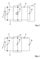
- Fig. 3
- eine Darstellung einer ersten Variante der erfindungsgemäßen Lösung,
- Fig. 4
- eine Darstellung einer zweiten Variante der erfindungsgemäßen Lösung,
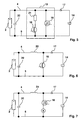
- Fig. 5
- eine Darstellung einer dritten Variante der erfindungsgemäßen Lösung,
- Fig. 6
- eine Darstellung einer vierten Variante der erfindungsgemäßen Lösung,
- Fig. 7
- eine Darstellung einer fünften Variante der erfindungsgemäßen Lösung.
- Fig. 1
- a schematic representation of a photovoltaic system with a generator and with an inverter according to the invention, which is connected to a power supply network (prior art),
- Fig.2
- a schematic representation of a photovoltaic system with a generator and with an inverter according to the invention with an intermediate circuit and a DC / AC converter in the form of a bridge circuit with subsequent transformer, which is connected to a power supply network,
- Fig. 3
- a representation of a first variant of the solution according to the invention,
- Fig. 4
- a representation of a second variant of the solution according to the invention,
- Fig. 5
- a representation of a third variant of the solution according to the invention,
- Fig. 6
- a representation of a fourth variant of the solution according to the invention,
- Fig. 7
- a representation of a fifth variant of the solution according to the invention.
In den Figuren sind gleiche Bauteile mit denselben Bezugszeichen versehen.In the figures, the same components are provided with the same reference numerals.
In Fig. 1 ist eine Photovoltaik-Anlage 1 abgebildet. Diese umfasst einen Generator 2, der als Photovoltaik-Generator ausgeführt ist. Er kann aus mehreren Modulen bestehen. Hier ist jedoch nur eines dargestellt. Der Photovoltaik-Generator 2 ist mit einem Wechselrichter 3 über Anschlussklemmen 4, 5 verbunden. An den Klemmen 4, 5 liegt eine Gleichspannung an. Der Wechselrichter 3, bestehend aus einem Zwischenkreis 11 und einem DC/AC-Wandler 12, ist an ein Stromversorgungsnetz 6, insbesondere an ein Niederspannungs-Netz angeschlossen. Die Anschlüsse 7, 8 dienen als Wechselspannungs-Netzausgang. Über die Anschlüsse 9 und 10 sind der Zwischenkreis 11 und der DC/AC-Wandler 12 miteinander verbunden. Der Photovoltaik-Generator 2 weist eine interne Kapazität, die als Kondensator 20 dargestellt ist, auf. Der DC/AC-Wandler 12 kann beispielsweise auch als DC/DC/AC-Wandler ausgeführt sein.In Fig. 1, a
Fig.2 zeigt eine Photovoltaik-Anlage 1 mit einem erfindungsgemäßen Wechselrichter 3. Der Wechselrichter 3 besteht aus einer erfindungsgemäßen Spannungs-Begrenzungsschaltung 13, die mit dem Photovoltaik-Generator 2 über die Anschlüsse 4 und 5 verbunden ist und dem Zwischenkreis 11 vorgeschaltet ist. Der DC/AC-Wandler 12 ist hier beispielhaft als Vollbrücke mit Halbleiterbauelementen 15 und einem Transformator 16, insbesondere einem 50Hz-60Hz Transformator, zur galvanischen Trennung des Netzes 6. ausgeführt. Prinzipiell sind für den DC/AC-Wandler auch andere für die Netzeinspeisung geeignete Topologien einsetzbar. Der Zwischenkreis dient zur Zwischenspeicherung elektrischer Energie, die durch Ansteuerung der Halbleiterschaltelemente 15 in Wechselstrom gewandelt wird. Der Zwischenkreis kann als Pufferkondensator ausgeführt sein. Es können dabei ein oder mehrere Pufferkondensatoren vorhanden sein.
In manchen Anlagen kann der Pufferkondensator durch eine Zwischenkreis-Drossel ersetzt oder ganz weggelassen werden. Fig. 2 zeigt also einen Wechselrichter 3 innerhalb einer Photovoltaik-Anlage 1 zum Anschluss an einen Photovoltaik-Generator 2 mit einem Gleichspannungseingang (Klemmen 4 und 5) und einen Wechselspannungs-Netzausgang (Klemmen 7 und 8)zur Einspeisung in ein Energieversorgungsnetz 6.2 shows a
In some systems, the buffer capacitor can be replaced by a DC link choke or omitted altogether. 2 thus shows an
Erfindungsgemäß ist dem Photovoltaik-Generator 2 eine Spannungsbegrenzungs-Einrichtung 13 nachgeschaltet, die in der einfachsten Ausführung aus einem Kurzschluss-Schaltelement besteht, das parallel zum Photovoltaik-Generator 2 angeschlossen und derart ansteuerbar ist, dass bei Überschreiten eines Spannungsgrenzwertes dieses so geschaltet wird, dass der Photovoltaik-Generator 2 in einem Kurzschlussbetrieb überführt wird und bei einem Unterschreiten des Spannungsgrenzwertes das Schaltelement wieder ausgeschaltet wird, so dass der Photovoltaik-Generator 2 den Kurzschlussbetrieb verlässt.According to the
Fig. 3 zeigt eine Variante mit einem Pufferkondensator 14 im Zwischenkreis 11. Dieser Pufferkondensator 14 wird über eine Schutzdiode 17 an den Photovoltaik-Generator 2 angeschlossen. Als Kurzschluss-Schaltelement 18 dient ein Transistor, vorzugsweise ein Leistungstransistor. Der Transistor liegt zwischen Schutzdiode 17 und Photovoltaik-Generator 2. Wird der Transistor angesteuert, sinkt die Spannung am Generator 2. Die Spannung am Kondensator 14 ist höher als an den Generatorklemmen, wodurch die Diode 17 sperrt. Dadurch wird der Pufferkondensator 14 bei Ansteuerung des Transistors 18 nicht entladen.FIG. 3 shows a variant with a
In Fig.4 ist der Leistungstransistor durch einen abschaltbaren Thyristor (GTO) ersetzt. Prinzipiell kann auch ein Thyristor mit einer geeigneten Löschschaltung verwendet werden. Ein Thyristor oder GTO zeichnet sich im Gegensatz zum IGBT durch höchste Energiedissipation bei Einhaltung des Grenzlastintegrals aus.In Figure 4, the power transistor is replaced by a turn-off thyristor (GTO). In principle, a thyristor with a suitable erase circuit can be used. In contrast to the IGBT, a thyristor or GTO is characterized by the highest energy dissipation while maintaining the limiting load integral.
Wie die Variante in Fig. 5 zeigt, kann in Reihe zum Kurzschluss-Schaltelement 18 ein Lastwiderstand 21 angeordnet sein. Durch diesen kann bei einem Einschalten des Halbleiterschalters 18 die interne Kapazität 20 des Photovoltaik-Generators 2 entladen werden. Auf diese Weise wird die in der Kapazität 20 enthaltene Energie nicht bzw. nicht vollständig im Leistungsschalter 18 in Wärme umgesetzt. Als Leistungsschalter 18 eignet sich ein Transistor, wie beispielsweise ein IGBT, oder ein ausschaltbarer Thyristor.As the variant in FIG. 5 shows, a
In einer besonderen Ausgestaltung kann wie in Fig.5 gezeigt parallel zum Leistungsschalter 18 und dessen vorgeschaltetem Lastwiderstand 21 ein weiterer Schalter 19 angeordnet sein. Im ersten Schritt wird der Leistungsschalter 18 geschlossen und der Entladevorgang des Kondensators 20 setzt ein. Ist die Spannung über dem Kondensator 20 auf eine niedrige Spannung gesunken, wird der Schalter 19 eingeschaltet. Diese Vorgehensweise hat den Vorteil, dass fast die gesamte in der Kapazität 20 enthaltene Energie im Widerstand 21 in Wärme umgesetzt wird, ohne dass dieser bei andauerndem Kurzschluss ständig Leistung aufnimmt.In a particular embodiment, as shown in Figure 5 parallel to the
Wird Schalter 19 wieder geöffnet, muss auch das Schaltelement 18 wieder ausgeschaltet werden. Der Leistungsschalter 18 kann auch sofort nach Zuschalten des Schalters 19 ausgeschaltet werden. Da Schalter 19 nur wenig Energie dissipieren muss, eignet sich in besonderer Weise, wie in Fig.5 gezeigt, ein MOSFET, insbesondere ein niederohmiger MOSFET.If
Alternativ kann auch zwischen dem Photovoltaik-Generator 2 und dem Kurzschluss-Schaltelement 18 eine Induktivität 22 angeschlossen sein, wie Fig. 6 zeigt. Die Induktivität 22 liegt zwischen Schalter 18 und Generator 2. Beim Einschalten des Schaltelementes 18 nimmt die Induktivität 22 dann zumindest einen Teil der in der Kapazität 20 enthaltenen Energie auf.Alternatively, an
Bei einigen Solarwechselrichtern ist dem DC/AC-Wandler 12 ein Hochsetzsteller vorgeschaltet, um eine Spannungsanpassung zur Wirkungsgradverbesserung zu erreichen. Damit ist eine Induktivität vorhanden, so dass keine zusätzliche Induktivität eingesetzt werden, weil die vorhandene Induktivität für den beschriebenen Zweck eingesetzt werden kann. Wenn keine Induktivität vorhanden ist, dann kann zwischen Generator 2 und dem Schaltelement 18 eine solche ergänzt werden.In some solar inverters, the DC /
Wird eine Hochsetzstellerschaltung eingesetzt, ist auch kein zusätzliches Schaltelement zum Herabsenken der Leerlaufspannung erforderlich, da der Hochsetzsteller dem DC/AC-Wandler 12 vorgeschaltet und dem Photovoltaik-Generator 2 nachgeschaltet ist. Der Hochsetzsteller wird dann entsprechend dem Verfahren aus Anspruch 11 getaktet, damit der Photovoltaik-Generator 2 im Kurzschlussbetrieb betrieben werden kann.If a step-up converter circuit is used, no additional switching element for lowering the open-circuit voltage is required since the step-up converter is connected upstream of the DC /
Wenn eine Induktivität 22 vorhanden ist, dann kann das Schaltelement 18 strombegrenzt betrieben werden, wie Fig. 7 veranschaulichen soll. Dazu wird der Strom durch das Schaltelement 18 bzw. durch die Induktivität 22 gemessen und bei einer bestimmten Stromstärke, die deutlich über dem normalen Generatorstrom liegt, das Schaltelement 18 ausgeschaltet. Mit einer bestimmten Taktfrequenz, bzw. nach Unterschreiten einer vorgegebenen, kleineren Stromstärke in der Induktivität 22, wird das Schaltelement 18 wieder eingeschaltet. Der Vorteil dieser Lösung liegt darin, dass der Energieinhalt der Eingangskapazität 20 über das Hochsetzstellerprinzip in den Pufferkondensator 14 übertragen wird und nicht in Wärme umgesetzt werden muss. Dadurch ergibt sich eine hohe Toleranz der Schaltung gegenüber der Größe der Eingangskapazität.If an
Die gezeigten Schaltungen sind Spannungsbegrenzungs- und Schutzschaltungen für Solarwechselrichter.The circuits shown are voltage limiting and protection circuits for solar inverters.
Bei den Schaltungen wird direkt, wie die Figuren 1, 2, 3, 4 und 5 zeigen, oder über eine Induktivität, wie die Figuren 6 und 7 zeigen, ein Leistungsschalter 18 parallel zum Photovoltaik-Generator 2 angeordnetIn the circuits, as shown in FIGS. 1, 2, 3, 4 and 5, or via an inductance, as shown in FIGS. 6 and 7, a
Der Wechselrichter 3 beinhaltet bei den dargestellten Varianten mindestens einen Pufferkondensator 14 und einen DC/AC-Wandler 12 , wobei der Pufferkondensator 14 vorzugsweise über eine Schutzdiode 17, an den Halbleiterschalter angeschlossen ist. Der Leistungsschalter 18 ist ein Halbleiterschalter, wie ein Transistor oder ein Thyristor, der ausschaltbar oder löschbar ist.The
Vorzugsweise wird die Spannung an dem Pufferkondensator 14 gemessen. Der Leistungsschalter 18 wird praktisch bei großen gemessenen Spannungen ein- und bei kleinen gemessenen Spannungen ausgeschaltet.Preferably, the voltage across the
Der Spannungsgrenzwert der nicht zu überschreitenden Spannung liegt vorzugsweise bei unter 600 Volt, so dass Vorschriften in USA eingehalten werden können.The voltage limit of the not to be exceeded voltage is preferably below 600 volts, so that regulations in the USA can be met.
Die Figuren 2 bis 7 zeigen beispielhafte Ausführungen von Schutz- und Regelschaltungen für Solaranlagen zum Einbau in Solarwechselrichter. Die Erfindung kann aber auch durch andere Schutz- und Regelschaltungen realisiert werden. So können grundsätzlich auch andere abschaltbare Halbleiterschaltelemente oder geeignete mechanische Schalter zum Kurzschließen eingesetzt werden. Ebenfalls kann der Zwischenkreis auch aus einer Drossel statt aus einem Pufferkondensator bestehen.Figures 2 to 7 show exemplary embodiments of protection and control circuits for solar systems for installation in solar inverters. The invention can also be realized by other protection and control circuits. In principle, other turn-off semiconductor switching elements or suitable mechanical switches can be used for short-circuiting. Likewise, the intermediate circuit can also consist of a throttle instead of a buffer capacitor.
Photovoltaik-Anlage
Generator
Wechselrichter
- 4,5
- Anschlussklemmen
generator
inverter
- 4.5
- terminals
Stromversorgungsnetz
- 7, 8
- Anschlussklemmen
- 9,10
- Anschlussklemmen
- 11
- Zwischenkreis
- 12
- DC/AC-Wandler
- 13
- Spannungsbegrenzungs-Schaltung
- 14
- Pufferkondensator
- 15
- Halbleiterschaltelemente
- 16
- Transformator
- 17
- Schutzdiode
- 18,19
- Kurzschluss-Schaltelement
- 20
- Interne Kapazität des Photovoltaik-
Generators 2
- 21
- Lastwiderstand
- 22
- Induktivität
- 7, 8
- terminals
- 9.10
- terminals
- 11
- DC
- 12
- DC / AC converter
- 13
- Voltage limiting circuit
- 14
- buffer capacitor
- 15
- Semiconductor switching elements
- 16
- transformer
- 17
- protection diode
- 18.19
- Short-circuit switching element
- 20
- Internal capacity of
photovoltaic generator 2
- 21
- load resistance
- 22
- inductance
Claims (19)
dadurch gekennzeichnet,
dass parallel zum Generator (2) mindestens ein Kurzschluss-Schaltelement (18) angeschlossen ist, das derart angesteuert wird, dass der Generator (2) entsprechend der Taktung im Kurzschlussbetrieb arbeitet, wodurch ein maximaler Spannungswert weder an den Anschlussklemmen (4;5) des Generators (2) noch zwischen den Anschlussklemmen (9;10) des Wechselrichters überschritten wird.Inverter (3), in particular for use in a photovoltaic system (1) with a DC input (terminals 4, 5) for connection to a generator (2) and an AC output (terminals 7, 8) for supply to a power grid (6) and a DC / AC converter (12) with semiconductor switching elements (15) and a DC link (11),
characterized,
in that at least one short-circuit switching element (18) is connected in parallel with the generator (2) and is operated in such a way that the generator (2) operates in short-circuit operation according to the timing, whereby a maximum voltage value is not applied to the connection terminals (4; 5) of the Generator (2) is still exceeded between the terminals (9; 10) of the inverter.
dadurch gekennzeichnet,
dass der Wechselrichter (3) im Zwischenkreis einen (12) Pufferkondensator (14) aufweist, der über eine Schutzdiode (17) an den Generator (2) angeschlossen ist, so dass der Pufferkondensator (14) bei Ansteuerung des Kurzschluss-Schaltelementes (18) nicht entladen wird.Inverter according to claim 1,
characterized,
in that the inverter (3) in the intermediate circuit has a (12) buffer capacitor (14) which is connected to the generator (2) via a protective diode (17) so that the buffer capacitor (14) is actuated when the short-circuit switching element (18) is actuated. not unloaded.
dadurch gekennzeichnet,
dass das Kurzschluss-Schaltelement (18) ein Halbleiterschalter ist.Inverter according to claim 1 or 2,
characterized,
that the short circuit switching element (18) is a semiconductor switch.
dadurch gekennzeichnet,
dass das Kurzschluss-Schaltelement (18) ein Transistor ist.Inverter according to claim 3,
characterized,
that the short-circuit switching member (18) is a transistor.
dadurch gekennzeichnet,
dass das Kurzschluss-Schaltelement (18) ein abschaltbarer Thyristor (GTO) ist.Inverter according to claim 3,
characterized,
that the short-circuit switching member (18) is a turn-off thyristor (GTO).
dadurch gekennzeichnet,
dass das Kurzschluss-Schaltelement (18) ein mechanischer Schalter ist.Inverter according to claim 1 or 2,
characterized,
that the short-circuit switching member (18) is a mechanical switch.
dadurch gekennzeichnet,
dass das Kurzschluss-Schaltelement (18) ein Schalter eines Hochsetzstellers innerhalb des Wechselrichters (3) ist.Inverter according to one of the preceding claims,
characterized,
that the short-circuit switching member (18) is a switch of a boost converter in the inverter (3).
dadurch gekennzeichnet,
dass in Reihe zum Schaltelement (18) ein Lastwiderstand (21) angeordnet ist.Inverter according to one of the preceding claims,
characterized,
in that a load resistor (21) is arranged in series with the switching element (18).
dadurch gekennzeichnet,
dass zwischen dem Generator (2) und dem Schaltelement (18) eine Induktivität (22) angeschlossen ist.Inverter according to one of the preceding claims,
characterized,
in that an inductance (22) is connected between the generator (2) and the switching element (18).
dadurch gekennzeichnet,
dass das Schaltelement (18) strombegrenzt betrieben wird.Inverter according to one of the preceding claims,
characterized,
that the switching element (18) is operated current limited.
dadurch gekennzeichnet,
dass der Generator (2) ein Photovoltaik-Generator ist.Inverter according to one of the preceding claims,
characterized,
that the generator (2) is a photovoltaic generator.
dadurch gekennzeichnet,
dass die Spannung an den Klemmen (9;10) des DC/AC-Wandlers (12) permanent erfasst wird und dass das Kurzschluss-Schaltelement (18) über eine Regelschaltung so angesteuert wird, dass es bei hohen Spannungen an den Anschlussklemmen (9; 10) ein- und bei niedrigen Spannungen an den Anschlussklemmen (9;10) ausgeschaltet wird.Method for protecting against overvoltage of a power generation plant, in particular a photovoltaic system (1) with an inverter (3) according to one of the preceding claims,
characterized,
in that the voltage at the terminals (9; 10) of the DC / AC converter (12) is permanently detected and that the short-circuiting switching element (18) is controlled via a control circuit in such a way that at high voltages at the connection terminals (9; 10) and switched off at low voltages at the terminals (9; 10).
dadurch gekennzeichnet,
dass die Regelschaltung ein Zweipunkt-Regler ist.Method according to claim 12,
characterized,
that the control circuit is a two-step controller.
dadurch gekennzeichnet,
dass die Regelschaltung ein P-Regler ist.Method according to claim 12,
characterized,
that the control circuit is a P-controller.
dadurch gekennzeichnet,
dass die Regelschaltung ein PI-Regler ist.Method according to claim 12,
characterized,
that the control circuit is a PI controller.
dadurch gekennzeichnet,
dass die Regelschaltung ein PID-Regler ist.Method according to claim 10,
characterized,
that the control circuit is a PID controller.
dadurch gekennzeichnet,
dass der Grenzwert der nicht zu überschreitenden hohen Spannung an den Anschlussklemmen (4;5) oder (9;10) bei 600 Volt liegt.Method according to one of claims 12 to 16,
characterized,
that the limit value of the not-border high voltage at the connection terminals (4; 5) or (9; 10) is 600 volts.
zum Schutz vor Überspannung durch Leerlaufspannung eines Generators (2) nach einem Einschalten der Stromerzeugungsanlage (1).Method according to one of claims 12 to 16,
for protection against overvoltage by open circuit voltage of a generator (2) after switching on the power generation plant (1).
dadurch gekennzeichnet,
dass der Generator (2) ein Photovoltaik-Generator ist.Inverter and method according to one of the preceding claims,
characterized,
that the generator (2) is a photovoltaic generator.
Priority Applications (5)
| Application Number | Priority Date | Filing Date | Title |
|---|---|---|---|
| DE502006004329T DE502006004329D1 (en) | 2006-10-21 | 2006-10-21 | Circuit device and method, in particular for photovoltaic generators |
| ES06022110T ES2327264T3 (en) | 2006-10-21 | 2006-10-21 | ELECTRICAL CIRCUIT DEVICE AND PROCEDURE, IN PARTICULAR FOR PHOTOVOLTAIC GENERATORS. |
| AT06022110T ATE437461T1 (en) | 2006-10-21 | 2006-10-21 | CIRCUIT DEVICE AND METHOD, IN PARTICULAR FOR PHOTOVOLTAIC GENERATORS |
| EP06022110A EP1914857B1 (en) | 2006-10-21 | 2006-10-21 | Circuit apparatus and method, in particular for photovoltaic generators |
| US11/904,404 US7924582B2 (en) | 2006-10-21 | 2007-09-27 | Switching device and method, in particular for photovoltaic generators |
Applications Claiming Priority (1)
| Application Number | Priority Date | Filing Date | Title |
|---|---|---|---|
| EP06022110A EP1914857B1 (en) | 2006-10-21 | 2006-10-21 | Circuit apparatus and method, in particular for photovoltaic generators |
Publications (2)
| Publication Number | Publication Date |
|---|---|
| EP1914857A1 true EP1914857A1 (en) | 2008-04-23 |
| EP1914857B1 EP1914857B1 (en) | 2009-07-22 |
Family
ID=37888009
Family Applications (1)
| Application Number | Title | Priority Date | Filing Date |
|---|---|---|---|
| EP06022110A Active EP1914857B1 (en) | 2006-10-21 | 2006-10-21 | Circuit apparatus and method, in particular for photovoltaic generators |
Country Status (5)
| Country | Link |
|---|---|
| US (1) | US7924582B2 (en) |
| EP (1) | EP1914857B1 (en) |
| AT (1) | ATE437461T1 (en) |
| DE (1) | DE502006004329D1 (en) |
| ES (1) | ES2327264T3 (en) |
Cited By (61)
| Publication number | Priority date | Publication date | Assignee | Title |
|---|---|---|---|---|
| EP2187510A1 (en) * | 2008-11-15 | 2010-05-19 | SMA Solar Technology AG | Inverter start up switch |
| EP2270947A2 (en) | 2009-07-02 | 2011-01-05 | Siemens Aktiengesellschaft | Method and device for energy distribution |
| DE102009032067A1 (en) * | 2009-07-07 | 2011-01-27 | Continental Automotive Gmbh | Device for protecting a DC-DC converter |
| EP2325984A1 (en) * | 2009-11-24 | 2011-05-25 | SMA Solar Technology AG | Start up of a photovoltiac field with high open circuit voltage |
| EP2362520A1 (en) * | 2010-02-26 | 2011-08-31 | Ziehl-Abegg AG | Inverter for photovoltaic systems |
| CN102460882A (en) * | 2009-05-26 | 2012-05-16 | 艾思玛太阳能技术股份公司 | Over-voltage protection for inverters having emv filter on input side |
| DE102011121197A1 (en) * | 2011-12-16 | 2013-06-20 | Sma Solar Technology Ag | Method for starting inverter of photovoltaic system for current production, involves starting converter when characteristic value exceeds threshold value or short circuiting terminal when characteristic value does not exceed threshold value |
| DE102012100864A1 (en) | 2012-02-02 | 2013-08-08 | Wagner & Co. Solartechnik Gmbh | Method for distributing total amount of current of local generator e.g. wind-power plant, involves executing consumption program, feed program and excess program, with which excess current amount is consumed by excess current consumer |
| EP2738929A1 (en) * | 2012-11-28 | 2014-06-04 | ABB Oy | Method for operating an inverter and an inverter |
| US8836162B2 (en) | 2010-02-26 | 2014-09-16 | Ziehl-Abegg Ag | Inverter for photovoltaic systems |
| EP2398123A3 (en) * | 2010-06-15 | 2015-02-25 | Ritter Elektronik GmbH | Method and safety circuit for operating a photovoltaic device |
| CN104597368A (en) * | 2015-01-15 | 2015-05-06 | 电子科技大学 | Current based open-circuit fault detection method for three-phase inverter |
| EP2374190B1 (en) | 2008-12-04 | 2015-10-14 | Solaredge Technologies Ltd. | System and method for protection in power installations |
| US9639106B2 (en) | 2012-03-05 | 2017-05-02 | Solaredge Technologies Ltd. | Direct current link circuit |
| US9831824B2 (en) | 2007-12-05 | 2017-11-28 | SolareEdge Technologies Ltd. | Current sensing on a MOSFET |
| US9853538B2 (en) | 2007-12-04 | 2017-12-26 | Solaredge Technologies Ltd. | Distributed power harvesting systems using DC power sources |
| US9853565B2 (en) | 2012-01-30 | 2017-12-26 | Solaredge Technologies Ltd. | Maximized power in a photovoltaic distributed power system |
| US9853490B2 (en) | 2006-12-06 | 2017-12-26 | Solaredge Technologies Ltd. | Distributed power system using direct current power sources |
| US9866098B2 (en) | 2011-01-12 | 2018-01-09 | Solaredge Technologies Ltd. | Serially connected inverters |
| US9869701B2 (en) | 2009-05-26 | 2018-01-16 | Solaredge Technologies Ltd. | Theft detection and prevention in a power generation system |
| US9876430B2 (en) | 2008-03-24 | 2018-01-23 | Solaredge Technologies Ltd. | Zero voltage switching |
| DE102016118039A1 (en) | 2016-09-23 | 2018-03-29 | Sma Solar Technology Ag | Solar module, photovoltaic system and voltage limiting method |
| US9935458B2 (en) | 2010-12-09 | 2018-04-03 | Solaredge Technologies Ltd. | Disconnection of a string carrying direct current power |
| US9948233B2 (en) | 2006-12-06 | 2018-04-17 | Solaredge Technologies Ltd. | Distributed power harvesting systems using DC power sources |
| US9960731B2 (en) | 2006-12-06 | 2018-05-01 | Solaredge Technologies Ltd. | Pairing of components in a direct current distributed power generation system |
| US9966766B2 (en) | 2006-12-06 | 2018-05-08 | Solaredge Technologies Ltd. | Battery power delivery module |
| US10061957B2 (en) | 2016-03-03 | 2018-08-28 | Solaredge Technologies Ltd. | Methods for mapping power generation installations |
| US10097007B2 (en) | 2006-12-06 | 2018-10-09 | Solaredge Technologies Ltd. | Method for distributed power harvesting using DC power sources |
| US10116217B2 (en) | 2007-08-06 | 2018-10-30 | Solaredge Technologies Ltd. | Digital average input current control in power converter |
| EP3142238B1 (en) | 2014-06-20 | 2019-01-23 | Huawei Technologies Co., Ltd. | Inverter and control device and method thereof, and inverter system |
| EP3435530A1 (en) * | 2017-07-25 | 2019-01-30 | Kostal Industrie Elektrik GmbH | Photovoltaic switcher assembly and method for operating the same |
| US10230310B2 (en) | 2016-04-05 | 2019-03-12 | Solaredge Technologies Ltd | Safety switch for photovoltaic systems |
| US10381977B2 (en) | 2012-01-30 | 2019-08-13 | Solaredge Technologies Ltd | Photovoltaic panel circuitry |
| US10396662B2 (en) | 2011-09-12 | 2019-08-27 | Solaredge Technologies Ltd | Direct current link circuit |
| US10461687B2 (en) | 2008-12-04 | 2019-10-29 | Solaredge Technologies Ltd. | Testing of a photovoltaic panel |
| US10468878B2 (en) | 2008-05-05 | 2019-11-05 | Solaredge Technologies Ltd. | Direct current power combiner |
| US10599113B2 (en) | 2016-03-03 | 2020-03-24 | Solaredge Technologies Ltd. | Apparatus and method for determining an order of power devices in power generation systems |
| US10608553B2 (en) | 2012-01-30 | 2020-03-31 | Solaredge Technologies Ltd. | Maximizing power in a photovoltaic distributed power system |
| US10637393B2 (en) | 2006-12-06 | 2020-04-28 | Solaredge Technologies Ltd. | Distributed power harvesting systems using DC power sources |
| US10651647B2 (en) | 2013-03-15 | 2020-05-12 | Solaredge Technologies Ltd. | Bypass mechanism |
| US10673229B2 (en) | 2010-11-09 | 2020-06-02 | Solaredge Technologies Ltd. | Arc detection and prevention in a power generation system |
| US10673222B2 (en) | 2010-11-09 | 2020-06-02 | Solaredge Technologies Ltd. | Arc detection and prevention in a power generation system |
| US10778025B2 (en) | 2013-03-14 | 2020-09-15 | Solaredge Technologies Ltd. | Method and apparatus for storing and depleting energy |
| US10931228B2 (en) | 2010-11-09 | 2021-02-23 | Solaredge Technologies Ftd. | Arc detection and prevention in a power generation system |
| US10931119B2 (en) | 2012-01-11 | 2021-02-23 | Solaredge Technologies Ltd. | Photovoltaic module |
| US11018623B2 (en) | 2016-04-05 | 2021-05-25 | Solaredge Technologies Ltd. | Safety switch for photovoltaic systems |
| US11081608B2 (en) | 2016-03-03 | 2021-08-03 | Solaredge Technologies Ltd. | Apparatus and method for determining an order of power devices in power generation systems |
| US11177768B2 (en) | 2012-06-04 | 2021-11-16 | Solaredge Technologies Ltd. | Integrated photovoltaic panel circuitry |
| US11177663B2 (en) | 2016-04-05 | 2021-11-16 | Solaredge Technologies Ltd. | Chain of power devices |
| US11264947B2 (en) | 2007-12-05 | 2022-03-01 | Solaredge Technologies Ltd. | Testing of a photovoltaic panel |
| US11296650B2 (en) | 2006-12-06 | 2022-04-05 | Solaredge Technologies Ltd. | System and method for protection during inverter shutdown in distributed power installations |
| US11309832B2 (en) | 2006-12-06 | 2022-04-19 | Solaredge Technologies Ltd. | Distributed power harvesting systems using DC power sources |
| US11569659B2 (en) | 2006-12-06 | 2023-01-31 | Solaredge Technologies Ltd. | Distributed power harvesting systems using DC power sources |
| US11569660B2 (en) | 2006-12-06 | 2023-01-31 | Solaredge Technologies Ltd. | Distributed power harvesting systems using DC power sources |
| US11598652B2 (en) | 2006-12-06 | 2023-03-07 | Solaredge Technologies Ltd. | Monitoring of distributed power harvesting systems using DC power sources |
| US11687112B2 (en) | 2006-12-06 | 2023-06-27 | Solaredge Technologies Ltd. | Distributed power harvesting systems using DC power sources |
| US11728768B2 (en) | 2006-12-06 | 2023-08-15 | Solaredge Technologies Ltd. | Pairing of components in a direct current distributed power generation system |
| US11735910B2 (en) | 2006-12-06 | 2023-08-22 | Solaredge Technologies Ltd. | Distributed power system using direct current power sources |
| US11855231B2 (en) | 2006-12-06 | 2023-12-26 | Solaredge Technologies Ltd. | Distributed power harvesting systems using DC power sources |
| US11881814B2 (en) | 2005-12-05 | 2024-01-23 | Solaredge Technologies Ltd. | Testing of a photovoltaic panel |
| US11888387B2 (en) | 2006-12-06 | 2024-01-30 | Solaredge Technologies Ltd. | Safety mechanisms, wake up and shutdown methods in distributed power installations |
Families Citing this family (29)
| Publication number | Priority date | Publication date | Assignee | Title |
|---|---|---|---|---|
| FR2912848B1 (en) * | 2007-02-20 | 2010-09-17 | Commissariat Energie Atomique | VOLTAGE LIMITER AND PROTECTION OF A PHOTOVOLTAIC MODULE |
| DE102007052301A1 (en) * | 2007-10-31 | 2009-05-07 | Kostal Industrie Elektrik Gmbh | Photovoltaic inverter unit |
| EP2157437B1 (en) * | 2008-08-19 | 2015-08-19 | SMA Solar Technology AG | Method for measuring a current, particularly through an earthing device |
| US8717047B2 (en) | 2008-08-19 | 2014-05-06 | Sma Solar Technology Ag | Method for measuring a current, in particular by means of a grounding apparatus |
| DE102008050543A1 (en) * | 2008-10-06 | 2010-04-15 | Siemens Aktiengesellschaft | Protection circuit for a DC link of an inverter, in particular a solar inverter, against overvoltages |
| DE102009025363B9 (en) * | 2009-06-18 | 2012-06-21 | Adensis Gmbh | Starting source inverter |
| AU2010275466B2 (en) | 2009-07-23 | 2015-11-26 | Enphase Energy, Inc. | Method and apparatus for detection and control of DC arc faults |
| WO2011024374A1 (en) * | 2009-08-24 | 2011-03-03 | 三菱電機株式会社 | Power conditioner for photovoltaic power generation |
| US7990743B2 (en) * | 2009-10-20 | 2011-08-02 | General Electric Company | System and method for decreasing solar collector system losses |
| US7855906B2 (en) | 2009-10-26 | 2010-12-21 | General Electric Company | DC bus voltage control for two stage solar converter |
| US9172312B2 (en) * | 2009-11-25 | 2015-10-27 | American Superconductor Corporation | Reducing photovoltaic array voltage during inverter re-enablement |
| US8050062B2 (en) | 2010-02-24 | 2011-11-01 | General Electric Company | Method and system to allow for high DC source voltage with lower DC link voltage in a two stage power converter |
| EP2363947B8 (en) * | 2010-03-03 | 2012-10-24 | SMA Solar Technology AG | Inverter with onboard network with multiple supplies |
| DE102010019267B4 (en) * | 2010-05-04 | 2012-08-30 | Adensis Gmbh | Photovoltaic system with targeted mismatching to the MPP and associated operating method |
| US8395919B2 (en) | 2010-07-29 | 2013-03-12 | General Electric Company | Photovoltaic inverter system and method of starting same at high open-circuit voltage |
| US8599586B2 (en) | 2010-08-28 | 2013-12-03 | General Electric Company | Power inverter system and method of starting same at high DC voltage |
| DE102010037760B4 (en) * | 2010-09-24 | 2015-05-28 | Ingenieurbüro Fred Tienken | Device and method for voltage isolation of electrical, running in a building or complex of buildings lines of a photovoltaic system, use of the device and system with the device and a photovoltaic system |
| DE102011077160A1 (en) * | 2011-06-07 | 2012-12-13 | Semikron Elektronik Gmbh & Co. Kg | Solar module and method for its operation |
| FR2977677B1 (en) | 2011-07-04 | 2013-08-23 | Commissariat Energie Atomique | DETECTION OF ELECTRIC ARCS IN PHOTOVOLTAIC FACILITIES |
| CN102510207B (en) * | 2011-08-29 | 2014-05-21 | 广州金升阳科技有限公司 | Short-circuit protection method for buffer output of DC/DC (Direct-Current/Direct-Current) power supply converter and buffer output circuit |
| US8897040B2 (en) | 2011-10-24 | 2014-11-25 | General Electric Company | Power converter systems and methods of operating a power converter system |
| DE102013113301A1 (en) | 2012-12-20 | 2014-06-26 | Sma Solar Technology Ag | Step-up converter for adjusting between voltage provided by photovoltaic generator and high voltage of input intermediate circuit of inverter, has discharge path running parallel to transverse branches and provided for discharge circuit |
| JP6213163B2 (en) * | 2013-01-24 | 2017-10-18 | オムロン株式会社 | Power conditioner, solar cell system, and abnormality determination method |
| FR3010260B1 (en) | 2013-08-29 | 2015-10-02 | Commissariat Energie Atomique | DETECTION OF ELECTRIC ARCS IN PHOTOVOLTAIC FACILITIES |
| FR3010261B1 (en) | 2013-08-29 | 2015-10-02 | Commissariat Energie Atomique | DETECTION OF AN ELECTRICAL ARC IN PARALLEL ON THE MAIN TERMINALS OF A PHOTOVOLTAIC INSTALLATION |
| AU2015364718B2 (en) | 2014-12-16 | 2019-11-28 | Marici Holdings The Netherlands B.V. | Energy panel arrangement power dissipation |
| JP2018506946A (en) | 2015-01-28 | 2018-03-08 | エービービー シュヴァイツ アクチェンゲゼルシャフト | Shut down energy panel equipment |
| AU2016219770A1 (en) | 2015-02-22 | 2017-09-07 | Abb Schweiz Ag | Photovoltaic string reverse polarity detection |
| CN110912398B (en) * | 2018-09-18 | 2021-09-28 | 台达电子工业股份有限公司 | Power conversion system with abnormal energy protection and operation method thereof |
Citations (12)
| Publication number | Priority date | Publication date | Assignee | Title |
|---|---|---|---|---|
| DE2630597A1 (en) * | 1975-07-08 | 1977-01-20 | Charbonnages De France | CIRCUIT BREAKER FOR AN ELECTRICAL CABLE |
| DE3725476A1 (en) * | 1987-07-31 | 1989-02-09 | Siemens Ag | Load supply circuit from power source of variable output - has changeover switch coupled to power source for selective coupling of pre-load or auxiliary feed voltage input |
| DE4041672A1 (en) * | 1990-12-22 | 1992-06-25 | Zsw | Monitoring unit for DC circuit for photovoltaic prodn. plants - which with line interference occuring within monitored stretch, current flow through monitored line section is interrupted using two monitoring lines |
| DE4102069A1 (en) * | 1991-01-24 | 1992-07-30 | Patent Treuhand Ges Fuer Elektrische Gluehlampen Mbh | CIRCUIT ARRANGEMENT FOR OPERATING A DISCHARGE LAMP |
| DE4325436A1 (en) * | 1993-07-29 | 1995-02-02 | Inst Luft & Kaeltetechnik Ggmbh | Method for regulating photovoltaic solar systems and circuit arrangements for carrying out the method |
| JPH07241077A (en) * | 1994-02-24 | 1995-09-12 | Sumitomo Electric Ind Ltd | Disconnector for dc power supply |
| JPH11312022A (en) * | 1998-04-28 | 1999-11-09 | Yaskawa Electric Corp | Inverter device for generating photovoltatic power and method for controlling the same device |
| EP1039621A2 (en) * | 1999-03-24 | 2000-09-27 | Sanyo Electric Co., Ltd. | Photovoltaic power generation device |
| JP2004070709A (en) * | 2002-08-07 | 2004-03-04 | Idec Izumi Corp | Power unit for intrinsically safe apparatus |
| JP2004254447A (en) * | 2003-02-20 | 2004-09-09 | Sharp Corp | Inverter and photovoltaic power generation system employing it |
| DE10312921A1 (en) * | 2003-03-22 | 2004-10-14 | Sma Regelsysteme Gmbh | Circuit arrangement, additional module and solar system |
| JP2006238629A (en) * | 2005-02-25 | 2006-09-07 | Mitsubishi Electric Corp | Power conversion apparatus |
Family Cites Families (7)
| Publication number | Priority date | Publication date | Assignee | Title |
|---|---|---|---|---|
| US4691159A (en) * | 1985-08-30 | 1987-09-01 | Hughes Aircraft Company | Partial shunt switching limiter for a spacecraft solar-panel or like power-source array |
| US4761722A (en) | 1987-04-09 | 1988-08-02 | Rca Corporation | Switching regulator with rapid transient response |
| AT406625B (en) * | 1998-11-12 | 2000-07-25 | Fronius Schweissmasch | VOLTAGE SWITCHING DEVICE |
| US6384579B2 (en) | 2000-06-27 | 2002-05-07 | Origin Electric Company, Limited | Capacitor charging method and charging apparatus |
| JP2002252986A (en) * | 2001-02-26 | 2002-09-06 | Canon Inc | Inverter, power supply system and method for reducing leakage current in power supply system |
| JP2005070709A (en) | 2003-08-28 | 2005-03-17 | Seiko Epson Corp | Image forming apparatus |
| JP2005151662A (en) * | 2003-11-13 | 2005-06-09 | Sharp Corp | Inverter device and distributed power supply system |
-
2006
- 2006-10-21 ES ES06022110T patent/ES2327264T3/en active Active
- 2006-10-21 EP EP06022110A patent/EP1914857B1/en active Active
- 2006-10-21 DE DE502006004329T patent/DE502006004329D1/en active Active
- 2006-10-21 AT AT06022110T patent/ATE437461T1/en active
-
2007
- 2007-09-27 US US11/904,404 patent/US7924582B2/en active Active
Patent Citations (12)
| Publication number | Priority date | Publication date | Assignee | Title |
|---|---|---|---|---|
| DE2630597A1 (en) * | 1975-07-08 | 1977-01-20 | Charbonnages De France | CIRCUIT BREAKER FOR AN ELECTRICAL CABLE |
| DE3725476A1 (en) * | 1987-07-31 | 1989-02-09 | Siemens Ag | Load supply circuit from power source of variable output - has changeover switch coupled to power source for selective coupling of pre-load or auxiliary feed voltage input |
| DE4041672A1 (en) * | 1990-12-22 | 1992-06-25 | Zsw | Monitoring unit for DC circuit for photovoltaic prodn. plants - which with line interference occuring within monitored stretch, current flow through monitored line section is interrupted using two monitoring lines |
| DE4102069A1 (en) * | 1991-01-24 | 1992-07-30 | Patent Treuhand Ges Fuer Elektrische Gluehlampen Mbh | CIRCUIT ARRANGEMENT FOR OPERATING A DISCHARGE LAMP |
| DE4325436A1 (en) * | 1993-07-29 | 1995-02-02 | Inst Luft & Kaeltetechnik Ggmbh | Method for regulating photovoltaic solar systems and circuit arrangements for carrying out the method |
| JPH07241077A (en) * | 1994-02-24 | 1995-09-12 | Sumitomo Electric Ind Ltd | Disconnector for dc power supply |
| JPH11312022A (en) * | 1998-04-28 | 1999-11-09 | Yaskawa Electric Corp | Inverter device for generating photovoltatic power and method for controlling the same device |
| EP1039621A2 (en) * | 1999-03-24 | 2000-09-27 | Sanyo Electric Co., Ltd. | Photovoltaic power generation device |
| JP2004070709A (en) * | 2002-08-07 | 2004-03-04 | Idec Izumi Corp | Power unit for intrinsically safe apparatus |
| JP2004254447A (en) * | 2003-02-20 | 2004-09-09 | Sharp Corp | Inverter and photovoltaic power generation system employing it |
| DE10312921A1 (en) * | 2003-03-22 | 2004-10-14 | Sma Regelsysteme Gmbh | Circuit arrangement, additional module and solar system |
| JP2006238629A (en) * | 2005-02-25 | 2006-09-07 | Mitsubishi Electric Corp | Power conversion apparatus |
Cited By (117)
| Publication number | Priority date | Publication date | Assignee | Title |
|---|---|---|---|---|
| US11881814B2 (en) | 2005-12-05 | 2024-01-23 | Solaredge Technologies Ltd. | Testing of a photovoltaic panel |
| US9853490B2 (en) | 2006-12-06 | 2017-12-26 | Solaredge Technologies Ltd. | Distributed power system using direct current power sources |
| US10447150B2 (en) | 2006-12-06 | 2019-10-15 | Solaredge Technologies Ltd. | Distributed power harvesting systems using DC power sources |
| US10673253B2 (en) | 2006-12-06 | 2020-06-02 | Solaredge Technologies Ltd. | Battery power delivery module |
| US11888387B2 (en) | 2006-12-06 | 2024-01-30 | Solaredge Technologies Ltd. | Safety mechanisms, wake up and shutdown methods in distributed power installations |
| US11962243B2 (en) | 2006-12-06 | 2024-04-16 | Solaredge Technologies Ltd. | Method for distributed power harvesting using DC power sources |
| US11855231B2 (en) | 2006-12-06 | 2023-12-26 | Solaredge Technologies Ltd. | Distributed power harvesting systems using DC power sources |
| US11735910B2 (en) | 2006-12-06 | 2023-08-22 | Solaredge Technologies Ltd. | Distributed power system using direct current power sources |
| US11728768B2 (en) | 2006-12-06 | 2023-08-15 | Solaredge Technologies Ltd. | Pairing of components in a direct current distributed power generation system |
| US11031861B2 (en) | 2006-12-06 | 2021-06-08 | Solaredge Technologies Ltd. | System and method for protection during inverter shutdown in distributed power installations |
| US11043820B2 (en) | 2006-12-06 | 2021-06-22 | Solaredge Technologies Ltd. | Battery power delivery module |
| US11687112B2 (en) | 2006-12-06 | 2023-06-27 | Solaredge Technologies Ltd. | Distributed power harvesting systems using DC power sources |
| US11682918B2 (en) | 2006-12-06 | 2023-06-20 | Solaredge Technologies Ltd. | Battery power delivery module |
| US11658482B2 (en) | 2006-12-06 | 2023-05-23 | Solaredge Technologies Ltd. | Distributed power harvesting systems using DC power sources |
| US11598652B2 (en) | 2006-12-06 | 2023-03-07 | Solaredge Technologies Ltd. | Monitoring of distributed power harvesting systems using DC power sources |
| US11594882B2 (en) | 2006-12-06 | 2023-02-28 | Solaredge Technologies Ltd. | Distributed power harvesting systems using DC power sources |
| US10230245B2 (en) | 2006-12-06 | 2019-03-12 | Solaredge Technologies Ltd | Battery power delivery module |
| US11594880B2 (en) | 2006-12-06 | 2023-02-28 | Solaredge Technologies Ltd. | Distributed power harvesting systems using DC power sources |
| US11063440B2 (en) | 2006-12-06 | 2021-07-13 | Solaredge Technologies Ltd. | Method for distributed power harvesting using DC power sources |
| US11594881B2 (en) | 2006-12-06 | 2023-02-28 | Solaredge Technologies Ltd. | Distributed power harvesting systems using DC power sources |
| US11575261B2 (en) | 2006-12-06 | 2023-02-07 | Solaredge Technologies Ltd. | Distributed power harvesting systems using DC power sources |
| US11575260B2 (en) | 2006-12-06 | 2023-02-07 | Solaredge Technologies Ltd. | Distributed power harvesting systems using DC power sources |
| US11569660B2 (en) | 2006-12-06 | 2023-01-31 | Solaredge Technologies Ltd. | Distributed power harvesting systems using DC power sources |
| US10097007B2 (en) | 2006-12-06 | 2018-10-09 | Solaredge Technologies Ltd. | Method for distributed power harvesting using DC power sources |
| US11183922B2 (en) | 2006-12-06 | 2021-11-23 | Solaredge Technologies Ltd. | Distributed power harvesting systems using DC power sources |
| US11476799B2 (en) | 2006-12-06 | 2022-10-18 | Solaredge Technologies Ltd. | Distributed power harvesting systems using DC power sources |
| US10637393B2 (en) | 2006-12-06 | 2020-04-28 | Solaredge Technologies Ltd. | Distributed power harvesting systems using DC power sources |
| US11569659B2 (en) | 2006-12-06 | 2023-01-31 | Solaredge Technologies Ltd. | Distributed power harvesting systems using DC power sources |
| US9966766B2 (en) | 2006-12-06 | 2018-05-08 | Solaredge Technologies Ltd. | Battery power delivery module |
| US11961922B2 (en) | 2006-12-06 | 2024-04-16 | Solaredge Technologies Ltd. | Distributed power harvesting systems using DC power sources |
| US9960667B2 (en) | 2006-12-06 | 2018-05-01 | Solaredge Technologies Ltd. | System and method for protection during inverter shutdown in distributed power installations |
| US11309832B2 (en) | 2006-12-06 | 2022-04-19 | Solaredge Technologies Ltd. | Distributed power harvesting systems using DC power sources |
| US11296650B2 (en) | 2006-12-06 | 2022-04-05 | Solaredge Technologies Ltd. | System and method for protection during inverter shutdown in distributed power installations |
| US9948233B2 (en) | 2006-12-06 | 2018-04-17 | Solaredge Technologies Ltd. | Distributed power harvesting systems using DC power sources |
| US9960731B2 (en) | 2006-12-06 | 2018-05-01 | Solaredge Technologies Ltd. | Pairing of components in a direct current distributed power generation system |
| US10516336B2 (en) | 2007-08-06 | 2019-12-24 | Solaredge Technologies Ltd. | Digital average input current control in power converter |
| US11594968B2 (en) | 2007-08-06 | 2023-02-28 | Solaredge Technologies Ltd. | Digital average input current control in power converter |
| US10116217B2 (en) | 2007-08-06 | 2018-10-30 | Solaredge Technologies Ltd. | Digital average input current control in power converter |
| US9853538B2 (en) | 2007-12-04 | 2017-12-26 | Solaredge Technologies Ltd. | Distributed power harvesting systems using DC power sources |
| US11264947B2 (en) | 2007-12-05 | 2022-03-01 | Solaredge Technologies Ltd. | Testing of a photovoltaic panel |
| US9831824B2 (en) | 2007-12-05 | 2017-11-28 | SolareEdge Technologies Ltd. | Current sensing on a MOSFET |
| US11183923B2 (en) | 2007-12-05 | 2021-11-23 | Solaredge Technologies Ltd. | Parallel connected inverters |
| US10644589B2 (en) | 2007-12-05 | 2020-05-05 | Solaredge Technologies Ltd. | Parallel connected inverters |
| US9979280B2 (en) | 2007-12-05 | 2018-05-22 | Solaredge Technologies Ltd. | Parallel connected inverters |
| US11693080B2 (en) | 2007-12-05 | 2023-07-04 | Solaredge Technologies Ltd. | Parallel connected inverters |
| US11894806B2 (en) | 2007-12-05 | 2024-02-06 | Solaredge Technologies Ltd. | Testing of a photovoltaic panel |
| US11183969B2 (en) | 2007-12-05 | 2021-11-23 | Solaredge Technologies Ltd. | Testing of a photovoltaic panel |
| US9876430B2 (en) | 2008-03-24 | 2018-01-23 | Solaredge Technologies Ltd. | Zero voltage switching |
| US11424616B2 (en) | 2008-05-05 | 2022-08-23 | Solaredge Technologies Ltd. | Direct current power combiner |
| US10468878B2 (en) | 2008-05-05 | 2019-11-05 | Solaredge Technologies Ltd. | Direct current power combiner |
| EP2187510A1 (en) * | 2008-11-15 | 2010-05-19 | SMA Solar Technology AG | Inverter start up switch |
| US8379418B2 (en) | 2008-11-15 | 2013-02-19 | Sma Solar Technology Ag | Power converter start-up circuit |
| US10461687B2 (en) | 2008-12-04 | 2019-10-29 | Solaredge Technologies Ltd. | Testing of a photovoltaic panel |
| EP2374190B1 (en) | 2008-12-04 | 2015-10-14 | Solaredge Technologies Ltd. | System and method for protection in power installations |
| US9869701B2 (en) | 2009-05-26 | 2018-01-16 | Solaredge Technologies Ltd. | Theft detection and prevention in a power generation system |
| US11867729B2 (en) | 2009-05-26 | 2024-01-09 | Solaredge Technologies Ltd. | Theft detection and prevention in a power generation system |
| EP2276136B2 (en) † | 2009-05-26 | 2018-04-04 | SMA Solar Technology AG | Excess voltage protection for inverter with input EMC filter |
| CN102460882B (en) * | 2009-05-26 | 2014-08-27 | 艾思玛太阳能技术股份公司 | Over-voltage protection for inverters having emv filter on input side |
| CN102460882A (en) * | 2009-05-26 | 2012-05-16 | 艾思玛太阳能技术股份公司 | Over-voltage protection for inverters having emv filter on input side |
| US10969412B2 (en) | 2009-05-26 | 2021-04-06 | Solaredge Technologies Ltd. | Theft detection and prevention in a power generation system |
| EP2270947A2 (en) | 2009-07-02 | 2011-01-05 | Siemens Aktiengesellschaft | Method and device for energy distribution |
| DE102009031550A1 (en) | 2009-07-02 | 2011-01-05 | Siemens Aktiengesellschaft | Device for energy distribution and method |
| DE102009032067A1 (en) * | 2009-07-07 | 2011-01-27 | Continental Automotive Gmbh | Device for protecting a DC-DC converter |
| US9331564B2 (en) | 2009-11-24 | 2016-05-03 | Sma Solar Technology Ag | Connecting a photovoltaic array at a high open circuit voltage |
| EP2325984A1 (en) * | 2009-11-24 | 2011-05-25 | SMA Solar Technology AG | Start up of a photovoltiac field with high open circuit voltage |
| WO2011064232A3 (en) * | 2009-11-24 | 2011-12-29 | Sma Solar Technology Ag | Start-up of a photovoltaic array with high open circuit voltage |
| WO2011064232A2 (en) | 2009-11-24 | 2011-06-03 | Sma Solar Technology Ag | Connecting a photovoltaic array at a high open circuit voltage |
| EP2362520A1 (en) * | 2010-02-26 | 2011-08-31 | Ziehl-Abegg AG | Inverter for photovoltaic systems |
| US8836162B2 (en) | 2010-02-26 | 2014-09-16 | Ziehl-Abegg Ag | Inverter for photovoltaic systems |
| EP2398123A3 (en) * | 2010-06-15 | 2015-02-25 | Ritter Elektronik GmbH | Method and safety circuit for operating a photovoltaic device |
| US10931228B2 (en) | 2010-11-09 | 2021-02-23 | Solaredge Technologies Ftd. | Arc detection and prevention in a power generation system |
| US10673229B2 (en) | 2010-11-09 | 2020-06-02 | Solaredge Technologies Ltd. | Arc detection and prevention in a power generation system |
| US11070051B2 (en) | 2010-11-09 | 2021-07-20 | Solaredge Technologies Ltd. | Arc detection and prevention in a power generation system |
| US10673222B2 (en) | 2010-11-09 | 2020-06-02 | Solaredge Technologies Ltd. | Arc detection and prevention in a power generation system |
| US11489330B2 (en) | 2010-11-09 | 2022-11-01 | Solaredge Technologies Ltd. | Arc detection and prevention in a power generation system |
| US11349432B2 (en) | 2010-11-09 | 2022-05-31 | Solaredge Technologies Ltd. | Arc detection and prevention in a power generation system |
| US9935458B2 (en) | 2010-12-09 | 2018-04-03 | Solaredge Technologies Ltd. | Disconnection of a string carrying direct current power |
| US11271394B2 (en) | 2010-12-09 | 2022-03-08 | Solaredge Technologies Ltd. | Disconnection of a string carrying direct current power |
| US11205946B2 (en) | 2011-01-12 | 2021-12-21 | Solaredge Technologies Ltd. | Serially connected inverters |
| US9866098B2 (en) | 2011-01-12 | 2018-01-09 | Solaredge Technologies Ltd. | Serially connected inverters |
| US10666125B2 (en) | 2011-01-12 | 2020-05-26 | Solaredge Technologies Ltd. | Serially connected inverters |
| US10396662B2 (en) | 2011-09-12 | 2019-08-27 | Solaredge Technologies Ltd | Direct current link circuit |
| DE102011121197B4 (en) * | 2011-12-16 | 2013-08-22 | Sma Solar Technology Ag | Procedure for commissioning an inverter and inverter |
| DE102011121197A1 (en) * | 2011-12-16 | 2013-06-20 | Sma Solar Technology Ag | Method for starting inverter of photovoltaic system for current production, involves starting converter when characteristic value exceeds threshold value or short circuiting terminal when characteristic value does not exceed threshold value |
| US10931119B2 (en) | 2012-01-11 | 2021-02-23 | Solaredge Technologies Ltd. | Photovoltaic module |
| US10381977B2 (en) | 2012-01-30 | 2019-08-13 | Solaredge Technologies Ltd | Photovoltaic panel circuitry |
| US11929620B2 (en) | 2012-01-30 | 2024-03-12 | Solaredge Technologies Ltd. | Maximizing power in a photovoltaic distributed power system |
| US9853565B2 (en) | 2012-01-30 | 2017-12-26 | Solaredge Technologies Ltd. | Maximized power in a photovoltaic distributed power system |
| US11620885B2 (en) | 2012-01-30 | 2023-04-04 | Solaredge Technologies Ltd. | Photovoltaic panel circuitry |
| US11183968B2 (en) | 2012-01-30 | 2021-11-23 | Solaredge Technologies Ltd. | Photovoltaic panel circuitry |
| US10992238B2 (en) | 2012-01-30 | 2021-04-27 | Solaredge Technologies Ltd. | Maximizing power in a photovoltaic distributed power system |
| US10608553B2 (en) | 2012-01-30 | 2020-03-31 | Solaredge Technologies Ltd. | Maximizing power in a photovoltaic distributed power system |
| DE102012100864A1 (en) | 2012-02-02 | 2013-08-08 | Wagner & Co. Solartechnik Gmbh | Method for distributing total amount of current of local generator e.g. wind-power plant, involves executing consumption program, feed program and excess program, with which excess current amount is consumed by excess current consumer |
| US10007288B2 (en) | 2012-03-05 | 2018-06-26 | Solaredge Technologies Ltd. | Direct current link circuit |
| US9639106B2 (en) | 2012-03-05 | 2017-05-02 | Solaredge Technologies Ltd. | Direct current link circuit |
| US11177768B2 (en) | 2012-06-04 | 2021-11-16 | Solaredge Technologies Ltd. | Integrated photovoltaic panel circuitry |
| EP2738929A1 (en) * | 2012-11-28 | 2014-06-04 | ABB Oy | Method for operating an inverter and an inverter |
| US9728959B2 (en) | 2012-11-28 | 2017-08-08 | Abb Oy | Method for operating an inverter and an inverter |
| US10778025B2 (en) | 2013-03-14 | 2020-09-15 | Solaredge Technologies Ltd. | Method and apparatus for storing and depleting energy |
| US11424617B2 (en) | 2013-03-15 | 2022-08-23 | Solaredge Technologies Ltd. | Bypass mechanism |
| US10651647B2 (en) | 2013-03-15 | 2020-05-12 | Solaredge Technologies Ltd. | Bypass mechanism |
| EP3142238B1 (en) | 2014-06-20 | 2019-01-23 | Huawei Technologies Co., Ltd. | Inverter and control device and method thereof, and inverter system |
| CN104597368B (en) * | 2015-01-15 | 2017-06-16 | 电子科技大学 | A kind of three-phase inverter open fault detection method based on electric current |
| CN104597368A (en) * | 2015-01-15 | 2015-05-06 | 电子科技大学 | Current based open-circuit fault detection method for three-phase inverter |
| US10599113B2 (en) | 2016-03-03 | 2020-03-24 | Solaredge Technologies Ltd. | Apparatus and method for determining an order of power devices in power generation systems |
| US11081608B2 (en) | 2016-03-03 | 2021-08-03 | Solaredge Technologies Ltd. | Apparatus and method for determining an order of power devices in power generation systems |
| US10540530B2 (en) | 2016-03-03 | 2020-01-21 | Solaredge Technologies Ltd. | Methods for mapping power generation installations |
| US11824131B2 (en) | 2016-03-03 | 2023-11-21 | Solaredge Technologies Ltd. | Apparatus and method for determining an order of power devices in power generation systems |
| US10061957B2 (en) | 2016-03-03 | 2018-08-28 | Solaredge Technologies Ltd. | Methods for mapping power generation installations |
| US11538951B2 (en) | 2016-03-03 | 2022-12-27 | Solaredge Technologies Ltd. | Apparatus and method for determining an order of power devices in power generation systems |
| US10230310B2 (en) | 2016-04-05 | 2019-03-12 | Solaredge Technologies Ltd | Safety switch for photovoltaic systems |
| US11870250B2 (en) | 2016-04-05 | 2024-01-09 | Solaredge Technologies Ltd. | Chain of power devices |
| US11018623B2 (en) | 2016-04-05 | 2021-05-25 | Solaredge Technologies Ltd. | Safety switch for photovoltaic systems |
| US11177663B2 (en) | 2016-04-05 | 2021-11-16 | Solaredge Technologies Ltd. | Chain of power devices |
| US11201476B2 (en) | 2016-04-05 | 2021-12-14 | Solaredge Technologies Ltd. | Photovoltaic power device and wiring |
| DE102016118039A1 (en) | 2016-09-23 | 2018-03-29 | Sma Solar Technology Ag | Solar module, photovoltaic system and voltage limiting method |
| EP3435530A1 (en) * | 2017-07-25 | 2019-01-30 | Kostal Industrie Elektrik GmbH | Photovoltaic switcher assembly and method for operating the same |
Also Published As
| Publication number | Publication date |
|---|---|
| US20080094867A1 (en) | 2008-04-24 |
| DE502006004329D1 (en) | 2009-09-03 |
| ATE437461T1 (en) | 2009-08-15 |
| ES2327264T3 (en) | 2009-10-27 |
| EP1914857B1 (en) | 2009-07-22 |
| US7924582B2 (en) | 2011-04-12 |
Similar Documents
| Publication | Publication Date | Title |
|---|---|---|
| EP1914857B1 (en) | Circuit apparatus and method, in particular for photovoltaic generators | |
| EP2187510B1 (en) | Inverter start up switch | |
| DE10120595B4 (en) | Solar Energy System | |
| EP1318589B1 (en) | Wind energy system and method for operating such a system | |
| EP2148417B1 (en) | Inverter apparatus for a photovoltaic generator with a plurality of inverters being serially coupled at their input side | |
| EP1323222B1 (en) | Island network and method for operation of an island network | |
| DE102006023563B4 (en) | Photovoltaic system | |
| DE60021795T2 (en) | Uninterruptible double power supply system | |
| EP1971018A1 (en) | Switching device for transformerless conversion of a direct voltage into an alternating voltage with two DC/DC converters and a DC/AC converter | |
| DE102009052461A1 (en) | Inverter circuitry | |
| DE102010060398A1 (en) | Method for operating a photovoltaic system for feeding electrical power into a medium-voltage network | |
| EP2355325A2 (en) | Switching device with a boost converter and inverter switch with such a switching device | |
| EP2451065B1 (en) | Inverter circuitry comprising a buck converter | |
| DE112016000220T5 (en) | POWER CONVERSION EQUIPMENT | |
| EP2911284B1 (en) | Switch assemblies and method for picking up electric power from multiple module strands | |
| DE102011000459B4 (en) | Method for supplying reactive current with a converter and converter arrangement and energy supply system | |
| DE102010028149B4 (en) | Redundancy module with self-supply of the active Entkoppelbauelements of a widely variable and low input voltage | |
| DE102013009781A1 (en) | Arrangement of semiconductor actuator e.g. N-channel MOSFET connected to power supply gate control stage, has semiconductor actuator whose output side is connected to input side of power supply unit in series | |
| EP1870996A1 (en) | Circuit for feeding electric energy in a electric utility grid | |
| EP3694105A1 (en) | Switching device for separating a current path | |
| EP2856625B1 (en) | Voltage supply for an inverter | |
| DE112019006840T5 (en) | Control device and solar power generation system | |
| DE102019107112B3 (en) | Switching device, voltage supply system, method for operating a switching device and manufacturing method | |
| DE102007029767B3 (en) | inverter | |
| DE102021119899B4 (en) | METHOD OF OPERATING AN INVERTER AND INVERTERS |
Legal Events
| Date | Code | Title | Description |
|---|---|---|---|
| PUAI | Public reference made under article 153(3) epc to a published international application that has entered the european phase |
Free format text: ORIGINAL CODE: 0009012 |
|
| 17P | Request for examination filed |
Effective date: 20070523 |
|
| AK | Designated contracting states |
Kind code of ref document: A1 Designated state(s): AT BE BG CH CY CZ DE DK EE ES FI FR GB GR HU IE IS IT LI LT LU LV MC NL PL PT RO SE SI SK TR |
|
| AX | Request for extension of the european patent |
Extension state: AL BA HR MK RS |
|
| 17Q | First examination report despatched |
Effective date: 20080403 |
|
| RAP1 | Party data changed (applicant data changed or rights of an application transferred) |
Owner name: SMA SOLAR TECHNOLOGY AG |
|
| AKX | Designation fees paid |
Designated state(s): AT BE BG CH CY CZ DE DK EE ES FI FR GB GR HU IE IS IT LI LT LU LV MC NL PL PT RO SE SI SK TR |
|
| GRAP | Despatch of communication of intention to grant a patent |
Free format text: ORIGINAL CODE: EPIDOSNIGR1 |
|
| GRAS | Grant fee paid |
Free format text: ORIGINAL CODE: EPIDOSNIGR3 |
|
| GRAA | (expected) grant |
Free format text: ORIGINAL CODE: 0009210 |
|
| AK | Designated contracting states |
Kind code of ref document: B1 Designated state(s): AT BE BG CH CY CZ DE DK EE ES FI FR GB GR HU IE IS IT LI LT LU LV MC NL PL PT RO SE SI SK TR |
|
| REG | Reference to a national code |
Ref country code: GB Ref legal event code: FG4D Free format text: NOT ENGLISH |
|
| REG | Reference to a national code |
Ref country code: CH Ref legal event code: EP |
|
| REG | Reference to a national code |
Ref country code: IE Ref legal event code: FG4D |
|
| REF | Corresponds to: |
Ref document number: 502006004329 Country of ref document: DE Date of ref document: 20090903 Kind code of ref document: P |
|
| REG | Reference to a national code |
Ref country code: ES Ref legal event code: FG2A Ref document number: 2327264 Country of ref document: ES Kind code of ref document: T3 |
|
| NLV1 | Nl: lapsed or annulled due to failure to fulfill the requirements of art. 29p and 29m of the patents act | ||
| PG25 | Lapsed in a contracting state [announced via postgrant information from national office to epo] |
Ref country code: FI Free format text: LAPSE BECAUSE OF FAILURE TO SUBMIT A TRANSLATION OF THE DESCRIPTION OR TO PAY THE FEE WITHIN THE PRESCRIBED TIME-LIMIT Effective date: 20090722 Ref country code: IS Free format text: LAPSE BECAUSE OF FAILURE TO SUBMIT A TRANSLATION OF THE DESCRIPTION OR TO PAY THE FEE WITHIN THE PRESCRIBED TIME-LIMIT Effective date: 20091122 Ref country code: SE Free format text: LAPSE BECAUSE OF FAILURE TO SUBMIT A TRANSLATION OF THE DESCRIPTION OR TO PAY THE FEE WITHIN THE PRESCRIBED TIME-LIMIT Effective date: 20090722 Ref country code: LT Free format text: LAPSE BECAUSE OF FAILURE TO SUBMIT A TRANSLATION OF THE DESCRIPTION OR TO PAY THE FEE WITHIN THE PRESCRIBED TIME-LIMIT Effective date: 20090722 |
|
| PG25 | Lapsed in a contracting state [announced via postgrant information from national office to epo] |
Ref country code: LV Free format text: LAPSE BECAUSE OF FAILURE TO SUBMIT A TRANSLATION OF THE DESCRIPTION OR TO PAY THE FEE WITHIN THE PRESCRIBED TIME-LIMIT Effective date: 20090722 Ref country code: PL Free format text: LAPSE BECAUSE OF FAILURE TO SUBMIT A TRANSLATION OF THE DESCRIPTION OR TO PAY THE FEE WITHIN THE PRESCRIBED TIME-LIMIT Effective date: 20090722 Ref country code: NL Free format text: LAPSE BECAUSE OF FAILURE TO SUBMIT A TRANSLATION OF THE DESCRIPTION OR TO PAY THE FEE WITHIN THE PRESCRIBED TIME-LIMIT Effective date: 20090722 Ref country code: SI Free format text: LAPSE BECAUSE OF FAILURE TO SUBMIT A TRANSLATION OF THE DESCRIPTION OR TO PAY THE FEE WITHIN THE PRESCRIBED TIME-LIMIT Effective date: 20090722 |
|
| REG | Reference to a national code |
Ref country code: IE Ref legal event code: FD4D |
|
| PG25 | Lapsed in a contracting state [announced via postgrant information from national office to epo] |
Ref country code: PT Free format text: LAPSE BECAUSE OF FAILURE TO SUBMIT A TRANSLATION OF THE DESCRIPTION OR TO PAY THE FEE WITHIN THE PRESCRIBED TIME-LIMIT Effective date: 20091122 Ref country code: BG Free format text: LAPSE BECAUSE OF FAILURE TO SUBMIT A TRANSLATION OF THE DESCRIPTION OR TO PAY THE FEE WITHIN THE PRESCRIBED TIME-LIMIT Effective date: 20091022 |
|
| BERE | Be: lapsed |
Owner name: SMA SOLAR TECHNOLOGY A.G. Effective date: 20091031 |
|
| PG25 | Lapsed in a contracting state [announced via postgrant information from national office to epo] |
Ref country code: EE Free format text: LAPSE BECAUSE OF FAILURE TO SUBMIT A TRANSLATION OF THE DESCRIPTION OR TO PAY THE FEE WITHIN THE PRESCRIBED TIME-LIMIT Effective date: 20090722 Ref country code: IE Free format text: LAPSE BECAUSE OF FAILURE TO SUBMIT A TRANSLATION OF THE DESCRIPTION OR TO PAY THE FEE WITHIN THE PRESCRIBED TIME-LIMIT Effective date: 20090722 Ref country code: RO Free format text: LAPSE BECAUSE OF FAILURE TO SUBMIT A TRANSLATION OF THE DESCRIPTION OR TO PAY THE FEE WITHIN THE PRESCRIBED TIME-LIMIT Effective date: 20090722 Ref country code: DK Free format text: LAPSE BECAUSE OF FAILURE TO SUBMIT A TRANSLATION OF THE DESCRIPTION OR TO PAY THE FEE WITHIN THE PRESCRIBED TIME-LIMIT Effective date: 20090722 |
|
| PLBE | No opposition filed within time limit |
Free format text: ORIGINAL CODE: 0009261 |
|
| STAA | Information on the status of an ep patent application or granted ep patent |
Free format text: STATUS: NO OPPOSITION FILED WITHIN TIME LIMIT |
|
| PG25 | Lapsed in a contracting state [announced via postgrant information from national office to epo] |
Ref country code: SK Free format text: LAPSE BECAUSE OF FAILURE TO SUBMIT A TRANSLATION OF THE DESCRIPTION OR TO PAY THE FEE WITHIN THE PRESCRIBED TIME-LIMIT Effective date: 20090722 Ref country code: MC Free format text: LAPSE BECAUSE OF NON-PAYMENT OF DUE FEES Effective date: 20091031 |
|
| 26N | No opposition filed |
Effective date: 20100423 |
|
| PG25 | Lapsed in a contracting state [announced via postgrant information from national office to epo] |
Ref country code: BE Free format text: LAPSE BECAUSE OF NON-PAYMENT OF DUE FEES Effective date: 20091031 Ref country code: GR Free format text: LAPSE BECAUSE OF FAILURE TO SUBMIT A TRANSLATION OF THE DESCRIPTION OR TO PAY THE FEE WITHIN THE PRESCRIBED TIME-LIMIT Effective date: 20091023 |
|
| PG25 | Lapsed in a contracting state [announced via postgrant information from national office to epo] |
Ref country code: LU Free format text: LAPSE BECAUSE OF NON-PAYMENT OF DUE FEES Effective date: 20091021 |
|
| GBPC | Gb: european patent ceased through non-payment of renewal fee |
Effective date: 20101021 |
|
| PG25 | Lapsed in a contracting state [announced via postgrant information from national office to epo] |
Ref country code: HU Free format text: LAPSE BECAUSE OF FAILURE TO SUBMIT A TRANSLATION OF THE DESCRIPTION OR TO PAY THE FEE WITHIN THE PRESCRIBED TIME-LIMIT Effective date: 20100123 |
|
| PG25 | Lapsed in a contracting state [announced via postgrant information from national office to epo] |
Ref country code: GB Free format text: LAPSE BECAUSE OF NON-PAYMENT OF DUE FEES Effective date: 20101021 Ref country code: TR Free format text: LAPSE BECAUSE OF FAILURE TO SUBMIT A TRANSLATION OF THE DESCRIPTION OR TO PAY THE FEE WITHIN THE PRESCRIBED TIME-LIMIT Effective date: 20090722 |
|
| PG25 | Lapsed in a contracting state [announced via postgrant information from national office to epo] |
Ref country code: CY Free format text: LAPSE BECAUSE OF FAILURE TO SUBMIT A TRANSLATION OF THE DESCRIPTION OR TO PAY THE FEE WITHIN THE PRESCRIBED TIME-LIMIT Effective date: 20090722 |
|
| REG | Reference to a national code |
Ref country code: DE Ref legal event code: R082 Ref document number: 502006004329 Country of ref document: DE |
|
| REG | Reference to a national code |
Ref country code: FR Ref legal event code: PLFP Year of fee payment: 10 |
|
| PGFP | Annual fee paid to national office [announced via postgrant information from national office to epo] |
Ref country code: AT Payment date: 20151022 Year of fee payment: 10 Ref country code: CZ Payment date: 20151015 Year of fee payment: 10 |
|
| REG | Reference to a national code |
Ref country code: FR Ref legal event code: PLFP Year of fee payment: 11 |
|
| REG | Reference to a national code |
Ref country code: AT Ref legal event code: MM01 Ref document number: 437461 Country of ref document: AT Kind code of ref document: T Effective date: 20161021 |
|
| PG25 | Lapsed in a contracting state [announced via postgrant information from national office to epo] |
Ref country code: CZ Free format text: LAPSE BECAUSE OF NON-PAYMENT OF DUE FEES Effective date: 20161021 |
|
| PG25 | Lapsed in a contracting state [announced via postgrant information from national office to epo] |
Ref country code: AT Free format text: LAPSE BECAUSE OF NON-PAYMENT OF DUE FEES Effective date: 20161021 |
|
| REG | Reference to a national code |
Ref country code: FR Ref legal event code: PLFP Year of fee payment: 12 |
|
| REG | Reference to a national code |
Ref country code: FR Ref legal event code: PLFP Year of fee payment: 13 |
|
| PGFP | Annual fee paid to national office [announced via postgrant information from national office to epo] |
Ref country code: ES Payment date: 20231117 Year of fee payment: 18 |
|
| PGFP | Annual fee paid to national office [announced via postgrant information from national office to epo] |
Ref country code: IT Payment date: 20231031 Year of fee payment: 18 Ref country code: FR Payment date: 20231023 Year of fee payment: 18 Ref country code: DE Payment date: 20231018 Year of fee payment: 18 Ref country code: CH Payment date: 20231102 Year of fee payment: 18 |