EP1318589B1 - Wind energy system and method for operating such a system - Google Patents
Wind energy system and method for operating such a system Download PDFInfo
- Publication number
- EP1318589B1 EP1318589B1 EP20010811203 EP01811203A EP1318589B1 EP 1318589 B1 EP1318589 B1 EP 1318589B1 EP 20010811203 EP20010811203 EP 20010811203 EP 01811203 A EP01811203 A EP 01811203A EP 1318589 B1 EP1318589 B1 EP 1318589B1
- Authority
- EP
- European Patent Office
- Prior art keywords
- wind energy
- energy storage
- busbar
- inverter
- busbar system
- Prior art date
- Legal status (The legal status is an assumption and is not a legal conclusion. Google has not performed a legal analysis and makes no representation as to the accuracy of the status listed.)
- Expired - Lifetime
Links
- 238000000034 method Methods 0.000 title claims description 12
- 238000004146 energy storage Methods 0.000 claims description 40
- 230000005540 biological transmission Effects 0.000 claims description 24
- 230000008878 coupling Effects 0.000 claims description 19
- 238000010168 coupling process Methods 0.000 claims description 19
- 238000005859 coupling reaction Methods 0.000 claims description 19
- 239000004065 semiconductor Substances 0.000 claims description 17
- 230000002950 deficient Effects 0.000 claims description 16
- 230000007547 defect Effects 0.000 claims description 11
- 238000002955 isolation Methods 0.000 claims description 8
- 238000000926 separation method Methods 0.000 description 7
- 230000001681 protective effect Effects 0.000 description 3
- 230000008054 signal transmission Effects 0.000 description 3
- 230000006378 damage Effects 0.000 description 2
- 239000000463 material Substances 0.000 description 2
- 230000008439 repair process Effects 0.000 description 2
- 239000003990 capacitor Substances 0.000 description 1
- 238000010276 construction Methods 0.000 description 1
- 230000001419 dependent effect Effects 0.000 description 1
- 238000011161 development Methods 0.000 description 1
- 230000018109 developmental process Effects 0.000 description 1
- 230000000694 effects Effects 0.000 description 1
- 230000000670 limiting effect Effects 0.000 description 1
- 238000012423 maintenance Methods 0.000 description 1
Images
Classifications
-
- H—ELECTRICITY
- H02—GENERATION; CONVERSION OR DISTRIBUTION OF ELECTRIC POWER
- H02J—CIRCUIT ARRANGEMENTS OR SYSTEMS FOR SUPPLYING OR DISTRIBUTING ELECTRIC POWER; SYSTEMS FOR STORING ELECTRIC ENERGY
- H02J3/00—Circuit arrangements for ac mains or ac distribution networks
- H02J3/36—Arrangements for transfer of electric power between ac networks via a high-tension dc link
-
- F—MECHANICAL ENGINEERING; LIGHTING; HEATING; WEAPONS; BLASTING
- F03—MACHINES OR ENGINES FOR LIQUIDS; WIND, SPRING, OR WEIGHT MOTORS; PRODUCING MECHANICAL POWER OR A REACTIVE PROPULSIVE THRUST, NOT OTHERWISE PROVIDED FOR
- F03D—WIND MOTORS
- F03D9/00—Adaptations of wind motors for special use; Combinations of wind motors with apparatus driven thereby; Wind motors specially adapted for installation in particular locations
- F03D9/20—Wind motors characterised by the driven apparatus
- F03D9/25—Wind motors characterised by the driven apparatus the apparatus being an electrical generator
- F03D9/255—Wind motors characterised by the driven apparatus the apparatus being an electrical generator connected to electrical distribution networks; Arrangements therefor
- F03D9/257—Wind motors characterised by the driven apparatus the apparatus being an electrical generator connected to electrical distribution networks; Arrangements therefor the wind motor being part of a wind farm
-
- H—ELECTRICITY
- H02—GENERATION; CONVERSION OR DISTRIBUTION OF ELECTRIC POWER
- H02J—CIRCUIT ARRANGEMENTS OR SYSTEMS FOR SUPPLYING OR DISTRIBUTING ELECTRIC POWER; SYSTEMS FOR STORING ELECTRIC ENERGY
- H02J3/00—Circuit arrangements for ac mains or ac distribution networks
- H02J3/38—Arrangements for parallely feeding a single network by two or more generators, converters or transformers
- H02J3/381—Dispersed generators
-
- H—ELECTRICITY
- H02—GENERATION; CONVERSION OR DISTRIBUTION OF ELECTRIC POWER
- H02J—CIRCUIT ARRANGEMENTS OR SYSTEMS FOR SUPPLYING OR DISTRIBUTING ELECTRIC POWER; SYSTEMS FOR STORING ELECTRIC ENERGY
- H02J2300/00—Systems for supplying or distributing electric power characterised by decentralized, dispersed, or local generation
- H02J2300/20—The dispersed energy generation being of renewable origin
- H02J2300/28—The renewable source being wind energy
-
- H—ELECTRICITY
- H02—GENERATION; CONVERSION OR DISTRIBUTION OF ELECTRIC POWER
- H02M—APPARATUS FOR CONVERSION BETWEEN AC AND AC, BETWEEN AC AND DC, OR BETWEEN DC AND DC, AND FOR USE WITH MAINS OR SIMILAR POWER SUPPLY SYSTEMS; CONVERSION OF DC OR AC INPUT POWER INTO SURGE OUTPUT POWER; CONTROL OR REGULATION THEREOF
- H02M1/00—Details of apparatus for conversion
- H02M1/32—Means for protecting converters other than automatic disconnection
- H02M1/325—Means for protecting converters other than automatic disconnection with means for allowing continuous operation despite a fault, i.e. fault tolerant converters
-
- H—ELECTRICITY
- H02—GENERATION; CONVERSION OR DISTRIBUTION OF ELECTRIC POWER
- H02M—APPARATUS FOR CONVERSION BETWEEN AC AND AC, BETWEEN AC AND DC, OR BETWEEN DC AND DC, AND FOR USE WITH MAINS OR SIMILAR POWER SUPPLY SYSTEMS; CONVERSION OF DC OR AC INPUT POWER INTO SURGE OUTPUT POWER; CONTROL OR REGULATION THEREOF
- H02M7/00—Conversion of ac power input into dc power output; Conversion of dc power input into ac power output
- H02M7/42—Conversion of dc power input into ac power output without possibility of reversal
- H02M7/44—Conversion of dc power input into ac power output without possibility of reversal by static converters
- H02M7/48—Conversion of dc power input into ac power output without possibility of reversal by static converters using discharge tubes with control electrode or semiconductor devices with control electrode
- H02M7/493—Conversion of dc power input into ac power output without possibility of reversal by static converters using discharge tubes with control electrode or semiconductor devices with control electrode the static converters being arranged for operation in parallel
-
- Y—GENERAL TAGGING OF NEW TECHNOLOGICAL DEVELOPMENTS; GENERAL TAGGING OF CROSS-SECTIONAL TECHNOLOGIES SPANNING OVER SEVERAL SECTIONS OF THE IPC; TECHNICAL SUBJECTS COVERED BY FORMER USPC CROSS-REFERENCE ART COLLECTIONS [XRACs] AND DIGESTS
- Y02—TECHNOLOGIES OR APPLICATIONS FOR MITIGATION OR ADAPTATION AGAINST CLIMATE CHANGE
- Y02E—REDUCTION OF GREENHOUSE GAS [GHG] EMISSIONS, RELATED TO ENERGY GENERATION, TRANSMISSION OR DISTRIBUTION
- Y02E10/00—Energy generation through renewable energy sources
- Y02E10/70—Wind energy
- Y02E10/72—Wind turbines with rotation axis in wind direction
-
- Y—GENERAL TAGGING OF NEW TECHNOLOGICAL DEVELOPMENTS; GENERAL TAGGING OF CROSS-SECTIONAL TECHNOLOGIES SPANNING OVER SEVERAL SECTIONS OF THE IPC; TECHNICAL SUBJECTS COVERED BY FORMER USPC CROSS-REFERENCE ART COLLECTIONS [XRACs] AND DIGESTS
- Y02—TECHNOLOGIES OR APPLICATIONS FOR MITIGATION OR ADAPTATION AGAINST CLIMATE CHANGE
- Y02E—REDUCTION OF GREENHOUSE GAS [GHG] EMISSIONS, RELATED TO ENERGY GENERATION, TRANSMISSION OR DISTRIBUTION
- Y02E10/00—Energy generation through renewable energy sources
- Y02E10/70—Wind energy
- Y02E10/76—Power conversion electric or electronic aspects
Definitions
- the invention relates to the field of wind turbines. It is based on a wind energy system and a method for operating such a system according to the preamble of the independent claims.
- Wind energy systems which are increasingly being used today as alternative energy sources due to dwindling energy resources, are usually built on land or offshore in the sea.
- a wind energy system is in the WO 00/74198 A1 disclosed.
- the wind energy system has at least two wind rotors, each one Rotor is mechanically connected to a generator and drives it.
- Each of the generators is connected to an associated passive rectifier unit.
- All rectifier units also have an energy storage circuit on their DC sides, each energy storage circuit is formed by corresponding inductors. However, these inductors cause by their large and expensive construction additional material costs and require a lot of space.
- Each energy storage circuit is followed by a step-up converter for adjusting the direct current of the corresponding rectifier unit.
- the energy storage circuits of WO 00/74198 A1 with the downstream boost converters are connected in parallel to a busbar and feed electrical energy into a transmission system, the transmission system is commonly designed as a two-phase busbar.
- a DC-DC controller is provided on the input side to adapt the high DC voltage required for a low-loss energy transmission.
- the transmission system is connected to a network coupling device having an input circuit formed by a DC capacitance.
- an inverter of the network coupling device with its DC side is connected to the input circuit, wherein the inverter is coupled at its AC voltage side via a power transformer to a common electrical supply network.
- the problem with such a wind energy system is when one or more rectifier units and / or the inverter of the network coupling device fails and the transmission system and thus all connected energy storage circuits and the input circuit of the network coupling device is shorted.
- a known solution is the active short-circuiting of all energy storage circuits by means of their boost converter, in particular by means of a thyristor of the corresponding boost converter, and the input circuit by means of the inverter. Due to the simultaneous short-circuit, the short-circuit currents distribute evenly across all rectifier units and the inverter. The separation of the electrical AC power supply network to interrupt the short-circuit currents is then carried out by a common mains circuit breaker.
- the rectifier unit If the rectifier unit is defective, it must be disconnected afterwards to to put the wind energy system back into operation. However, in such a separation, in particular from the corresponding energy storage circuit, the leadership of the previously flowing short-circuit current must be able to be controlled until the deceleration of the associated generator to standstill. In the wind energy system after the WO 00/74198 A1 is such separation from the energy storage circuit not provided and therefore not possible. In addition, rapid signal transmission to the boost converters and the inverter must occur in order to trigger the simultaneous active short-circuit mentioned above in the event of a defect of one or more rectifier units and / or the inverter.
- the object of the invention is therefore to provide a wind energy system in which a device connected to a generator of the wind energy rectifier unit can be selectively separated from the wind energy system in case of failure and / or defect, with an uninterrupted continued operation of the remaining components of the wind energy system is possible, and especially simple and robust and can be realized with little circuit complexity. Furthermore, a method is to be specified with which the wind energy system according to the invention can be operated in a particularly simple and efficient manner.
- the wind energy system comprises at least two generators driven by wind rotors, a rectifier unit being provided for each generator is at whose inputs the associated generator is connected. Furthermore, the wind energy system has an energy storage circuit for each rectifier unit, wherein the energy storage circuit is connected to outputs of the associated rectifier unit. Furthermore, a first busbar is provided, to which the energy storage circuits are connected in parallel. A transmission system is connected to the first busbar, wherein a network coupling device is provided with which the transmission system is connected on the input side. Furthermore, the network coupling device is coupled via a power transformer to an electrical AC power supply network. According to the invention, each rectifier unit is designed as an active rectifier unit with controllable power semiconductor components.
- each energy storage circuit has at least one DC voltage capacity and, in at least one connection to the first busbar, at least one first protective switch in the form of a semiconductor switch.
- the active rectifier unit and the energy storage circuit with the DC voltage capacity can advantageously be carried out an adjustment of a variable load-independent DC voltage of the energy storage circuit.
- the voltage of the transmission system which, as mentioned above, is connected to the energy storage circuits via the first busbar, can be increased, so that the electrical power dissipation can be advantageously reduced, in particular in the case of a transmission system extending, for example, over a long distance.
- the wind energy system comes with a minimum number of components, especially because of the use of DC capacities for the energy storage circuits little space and can be realized with a small amount of circuit complexity.
- the wind energy system designed according to the invention due to the simple structure and the few components as very maintenance and repair friendly and is also very robust.
- the inventive method allows a particularly efficient operation of the wind energy system, in addition, a very high availability of the wind energy system can be achieved.
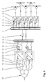
- Fig. 1 an embodiment of a wind energy system according to the invention is shown.
- the wind energy system comprises at least two generators 2 driven by wind rotors 1.
- a rectifier unit 3 is provided for each of these generators 2, to whose inputs, in particular to AC voltage inputs, the associated generator 2 is connected.
- Each rectifier unit 3 has an energy storage circuit 4, which is connected to outputs, in particular to DC voltage outputs of the associated rectifier unit 3.
- Fig. 1 are all energy storage circuits 4 connected in parallel to a first busbar 7, wherein on the first busbar 7 also a transmission system 8 is connected.
- a network coupling device 15 is provided, with which the transmission system 8 is connected on the input side.
- the network coupling device 15 is after Fig. 1 is coupled via a power transformer 16 to an electrical AC power supply not shown for clarity.
- each rectifier unit is designed as an active rectifier unit with controllable power semiconductor components, and each energy storage circuit 4 also has at least one DC voltage capacitor, whereby an adjustment of a variable load-independent DC voltage of the respective energy storage circuit 4 is advantageously carried out by means of the associated active rectifier unit 3.
- This makes it possible to increase the voltage of the transmission system 8.
- a transmission system 8 which extends over a long distance, for example, in an offshore application of the wind energy system
- the electric power loss can be reduced particularly efficiently with such a voltage increase.
- boost converter as known from the prior art, this can be advantageously dispensed with.
- a DC-DC controller with a complex control for a large Voltage increase as also known from the prior art, can also be advantageously saved and only needs to be used optionally for extremely long transmission distances.
- each energy storage circuit 4 has at least one first circuit breaker 5 in the form of a semiconductor switch in at least one connection to the first busbar 7.
- first circuit breaker 5 in the form of a semiconductor switch in at least one connection to the first busbar 7.
- the first circuit breaker 5 is preferably formed as a semiconductor diode. As a result, the circuit and control effort can be reduced accordingly, since the first circuit breaker 5 requires no expensive control.
- each energy storage circuit 4 according Fig. 1 in each connection to the first busbar 7 at least a first separating means 6, wherein the first separating means 6, for example in the form of a mechanical switch, the electrical isolation of the energy storage circuit 4 of the first bus 7 are used.
- the first separating means 6 it is thus advantageously possible to separate the defective rectifier unit 3 galvanically from the wind energy system, in particular from the first busbar 7.
- the first separating means 6 are designed for separating a virtually de-energized state and actuated by hand, so that the circuit and control effort can be kept low.
- the network coupling device 15 is according to Fig. 1 connected via a second busbar 9 with the transmission system 8.
- the network coupling device 15 also has at least one inverter 13 and one input circuit 12 for each inverter 13, wherein at an inverter number of greater than or equal to two, the input circuits 12 are connected in parallel with the second busbar 9.
- each input circuit 12 comprises at least one DC voltage capacity.
- the advantage of the parallel connection with an inverter number of greater than or equal to two is that partial failure of the non-defective inverter 13 can be achieved in the event of a failure. It is also possible by an inverter number of greater than or equal to two, with a suitable transformer circuit of the power transformer 16 to achieve a reduction of the harmonics.
- the DC voltage capacity also has the advantageous effect of dissipating the switching-frequency current harmonics generated by the associated inverter 13 in the shortest path and thus to a great extent keeping away from the transmission system 8.
- each input circuit 12 according to the invention in at least one connection to the second busbar 9 at least a second circuit breaker 11 in the form of a semiconductor switch, wherein the second circuit breaker 11 is advantageously a controllable power semiconductor switch.
- the second circuit breaker 11 is advantageously a controllable power semiconductor switch.
- a detector device For detecting an exceeding of the above-mentioned maximum permissible current value of the current flow, a detector device is installed in order to be able to switch off the second protective switch 11 designed as a controllable power semiconductor switch via a drive device.
- the corresponding detector devices and control devices of the individual second circuit breaker 11 are omitted for the sake of simplicity.
- each input circuit 12 has at least one second separating means 10 in each connection to the second busbar 9, the second separating means 10 serving for the galvanic separation of the input circuit 12 from the second busbar 9.
- the second separating means 10 are designed for separating a virtually de-energized state, actuated by hand and, for example, carried out mechanically, so that the circuit and control effort can be kept low.
- each inverter 13 is connected with its AC voltage side to the power transformer 16, wherein in each connection to the power transformer 16 at least a third separating means 14 is provided.
- the third separating means 14 are used for galvanic isolation of the inverter 13 from the power transformer 16.
- the mains transformer 16 in the start phase of the wind energy system at a pre-charge of the DC voltage capacity of the input circuit 12 by a Vorlade are kept separated from the inverter 13 until the DC voltage capacity is charged.
- the third separating means 14, together with the second separating means 10 can switch the associated inverter 13 de-energized in order to maintain it without it being defective or failing, with the wind energy system advantageously continuing to be operated.
- the third separating means 14 are designed for separating a virtually de-energized state, actuated by hand and, for example mechanically executed, so that the circuit and control effort, as already mentioned in the first and second separating means 6, 10, even in the third separating means 14 low can be held.
- the inventive method for operating the wind energy system is driven by the at least two wind turbines 1 driven generators 2 electrical energy generated for feeding into the electrical AC power supply network.
- the associated first or first circuit breaker 5 is opened. Through this opening of the first or the first circuit breaker 5 in case of failure or failure of the corresponding rectifier unit 3, this is easily and quickly separated from the wind energy system, in particular from the first busbar 7, so that the wind energy system can continue to operate advantageous uninterrupted.
- the defective rectifier unit 3 is galvanically separated from the first busbar 7 by the associated first isolating means 6.
- the defective rectifier unit 3 can advantageously be repaired or replaced without danger.
- the associated second protective switch 11 upon occurrence of a defect on one of the inverters 13, the associated second protective switch 11 is opened. Through this opening of the second or the second circuit breaker 11 in case of failure or failure of the corresponding inverter 13 this is easily and quickly separated from the wind energy system, in particular from the second busbar 9, so that the wind energy system can be advantageously continued uninterrupted. Further, after the opening of the or the associated second circuit breaker 11, the defective inverter 13 is galvanically separated from the second busbar 9 by the associated second separating means 10. By means of the galvanic isolation by the second separating means 10, the defective inverter 13 can advantageously be repaired or replaced without risk. Moreover, the defective inverter 13 is also preferably electrically isolated from the power transformer 16 by the associated third isolation means 14, thereby providing additional security when repairs are made to the defective or serviceable inverter 13 or it is replaced.
- the wind energy system according to the invention is an extremely simple and cost-effective and reliable solution, since in particular components in their Failure and / or defect can be selectively separated from the wind energy system, with an uninterrupted continued operation of the remaining components of the wind energy system is ensured.
- a simple, stable and very efficient operation of the wind energy system according to the invention is made possible by the inventive method, whereby a particularly high availability of the wind energy system can be achieved.
Description
Die Erfindung bezieht sich auf das Gebiet der Windenergieanlagen. Sie geht aus von einem Windenergiesystem und einem Verfahren zum Betrieb eines solchen Systems gemäss dem Oberbegriff der unabhängigen Ansprüche.The invention relates to the field of wind turbines. It is based on a wind energy system and a method for operating such a system according to the preamble of the independent claims.
Windenergiesysteme, wie sie heute aufgrund schwindender Energieressourcen verstärkt als alternative Energielieferanten eingesetzt werden, werden gängigerweise an Land oder vor der Küste im Meer errichtet. Ein derartiges Windenergiesystem ist in der
Problematisch bei einem solchen Windenergiesystem ist es, wenn ein oder mehrere Gleichrichtereinheiten und/oder der Wechselrichter der Netzkopplungseinrichtung ausfallen und das Übertragungssystem und somit alle daran verbundenen Energiespeicherkreise und der Eingangskreis der Netzkopplungseinrichtung kurzgeschlossen wird. Eine bekannte Lösung ist das aktive Kurzschliessen sämtlicher Energiespeicherkreise mittels ihrer Hochsetzsteller, insbesondere mittels eines Thyristors des entsprechenden Hochsetzstellers, und des Eingangskreises mittels des Wechselrichters. Durch den gleichzeitigen Kurzschluss verteilen sich die Kurzschlussströme gleichmässig auf sämtliche Gleichrichtereinheiten und den Wechselrichter. Die Abtrennung des elektrischen Wechselspannungsversorgungsnetzes zur Unterbrechung der Kurzschlussströme erfolgt danach durch einen gängigen Netzleistungsschalter. Bei einer defekten Gleichrichtereinheit muss diese danach abgetrennt werden, um das Windenergiesystem wieder in Betrieb setzen zu können. Jedoch muss bei einer solchen Abtrennung, insbesondere vom entsprechenden Energiespeicherkreis, die Führung des zuvor fliessenden Kurzschlussstromes bis zum erfolgten Abbremsen des zugehörigen Generators in den Stillstand beherrscht werden können. Bei dem Windenergiesystem nach der
Aufgabe der Erfindung ist es deshalb, ein Windenergiesystem anzugeben, bei dem eine an einem Generator des Windenergiesystems angeschlossene Gleichrichtereinheit bei deren Ausfall und/oder Defekt selektiv vom Windenergiesystem abgetrennt werden kann, wobei ein unterbrechungsfreier Weiterbetrieb der restlichen Komponenten des Windenergiesystems möglich ist, und welches besonders einfach und robust aufgebaut ist und mit geringem Schaltungsaufwand realisiert werden kann. Ferner ist ein Verfahren anzugeben, mit dem das erfindungsgemässe Windenergiesystem besonders einfach und effizient betrieben werden kann. Diese Aufgaben werden durch die Merkmale des Anspruchs 1 und 11 gelöst. In den Unteransprüchen sind vorteilhafte Weiterbildungen der Erfindung angegeben.The object of the invention is therefore to provide a wind energy system in which a device connected to a generator of the wind energy rectifier unit can be selectively separated from the wind energy system in case of failure and / or defect, with an uninterrupted continued operation of the remaining components of the wind energy system is possible, and especially simple and robust and can be realized with little circuit complexity. Furthermore, a method is to be specified with which the wind energy system according to the invention can be operated in a particularly simple and efficient manner. These objects are achieved by the features of
Das erfindungsgemässe Windenergiesystem umfasst mindestens zwei mittels Windrotoren angetriebene Generatoren, wobei eine Gleichrichtereinheit für jeden Generator vorgesehen ist, an deren Eingängen der zugehörige Generator angeschlossen ist. Desweiteren weist das Windenergiesystem einen Energiespeicherkreis für jede Gleichrichtereinheit auf, wobei der Energiespeicherkreis an Ausgängen der zugehörigen Gleichrichtereinheit angeschlossen ist. Ferner ist eine erste Verschienung vorgesehen, an welcher die Energiespeicherkreise parallel verbunden sind. Mit der ersten Verschienung ist ein Übertragungssystem verbunden, wobei eine Netzkopplungseinrichtung vorgesehen ist, mit der das Übertragungssystem eingangsseitig verbunden ist. Weiterhin ist die Netzkopplungseinrichtung über einen Netztransformator an ein elektrisches Wechselspannungsversorgungsnetz angekoppelt. Erfindungsgemäss ist jede Gleichrichtereinheit als aktive Gleichrichtereinheit mit ansteuerbaren Leistungshalbleiterbauelementen ausgebildet. Ferner weist jeder Energiespeicherkreis mindestens eine Gleichspannungskapazität und in mindestens einer Verbindung zur ersten Verschienung mindestens einen ersten Schutzschalter in Form eines Halbleiterschalters auf. Mittels der aktiven Gleichrichtereinheit und des Energiespeicherkreises mit der Gleichspannungskapazität kann vorteilhaft eine Einstellung einer variablen lastunabhängigen Gleichspannung des Energiespeicherkreises durchgeführt werden. Dadurch kann die Spannung des Übertragungssystems, welches, wie vorstehend erwähnt, über die erste Verschienung mit den Energiespeicherkreisen verbunden ist, erhöht werden, so dass sich die elektrische Verlustleistung vorteilhaft insbesondere bei einem Übertragungssystem, welches sich beispielsweise über eine lange Distanz erstreckt, reduzieren lässt. Darüber hinaus kann im Falle eines Defektes und/oder Ausfalls einer oder mehrerer Gleichrichtereinheiten ein über dem maximal zulässigen Stromwert liegender Stromfluss von der ersten Verschienung in den jeweiligen Energiespeicherkreis und/oder ein Stromfluss vom Energiespeicherkreis in die erste Verschienung mit dem jeweiligen ersten Schutzschalter in gewünschter Weise unterbrochen werden. Durch diese Unterbrechung erfolgt eine schnelle selektive Abtrennung der entsprechenden Gleichrichtereinheit vom Windenergiesystem, so dass vorteilhaft ein unterbrechungsfreier Weiterbetrieb der restlichen Komponenten des Windenergiesystems ermöglicht werden kann. Der erste Schutzschalter in Form des Halbleiterschalters bleibt dabei vorteilhaft frei von einer Beschädigung oder Zerstörung.The wind energy system according to the invention comprises at least two generators driven by wind rotors, a rectifier unit being provided for each generator is at whose inputs the associated generator is connected. Furthermore, the wind energy system has an energy storage circuit for each rectifier unit, wherein the energy storage circuit is connected to outputs of the associated rectifier unit. Furthermore, a first busbar is provided, to which the energy storage circuits are connected in parallel. A transmission system is connected to the first busbar, wherein a network coupling device is provided with which the transmission system is connected on the input side. Furthermore, the network coupling device is coupled via a power transformer to an electrical AC power supply network. According to the invention, each rectifier unit is designed as an active rectifier unit with controllable power semiconductor components. Furthermore, each energy storage circuit has at least one DC voltage capacity and, in at least one connection to the first busbar, at least one first protective switch in the form of a semiconductor switch. By means of the active rectifier unit and the energy storage circuit with the DC voltage capacity can advantageously be carried out an adjustment of a variable load-independent DC voltage of the energy storage circuit. As a result, the voltage of the transmission system, which, as mentioned above, is connected to the energy storage circuits via the first busbar, can be increased, so that the electrical power dissipation can be advantageously reduced, in particular in the case of a transmission system extending, for example, over a long distance. In addition, in the case of a defect and / or failure of one or more rectifier units lying above the maximum current value current flow from the first busbar into the respective energy storage circuit and / or a current flow from the energy storage circuit in the first busbar with the respective first circuit breaker in the desired manner to be interrupted. By this interruption, a rapid selective separation of the corresponding rectifier unit from the wind energy system, so that advantageously a continuous operation of the remaining components of the wind energy system can be made possible. The first circuit breaker in the form of the semiconductor switch remains advantageous free from damage or destruction.
Weiterhin kommt das Windenergiesystem mit einer minimalen Anzahl an Komponenten aus, benötigt insbesondere wegen des Einsatzes von Gleichspannungskapazitäten für die Energiespeicherkreise wenig Platz und kann mit einem geringen Mass an Schaltungsaufwand realisiert werden. Zudem gestaltet sich das Windenergiesystem nach der Erfindung aufgrund des einfachen Aufbaus und der wenigen Komponenten als sehr wartungs- und reparaturfreundlich und ist zudem sehr robust.Furthermore, the wind energy system comes with a minimum number of components, especially because of the use of DC capacities for the energy storage circuits little space and can be realized with a small amount of circuit complexity. In addition, the wind energy system designed according to the invention due to the simple structure and the few components as very maintenance and repair friendly and is also very robust.
Beim erfindungsgemässen Verfahren zum Betrieb des Windenergiesystems wird durch die mindestens zwei mittels Windrotoren angetriebenen Generatoren elektrische Energie zur Einspeisung in das elektrische Wechselspannungsversorgungsnetz erzeugt. Erfindungsgemäss wird bei Eintreten eines Defektes und oder Ausfalls an einer der Gleichrichtereinheiten der oder die zugehörigen ersten Schutzschalter geöffnet. Dadurch, dass der oder die zugehörigen ersten Schutzschalter bei Defekt beziehungsweise Ausfall einer Gleichrichtereinheit geöffnet werden, wird die entsprechende Gleichrichtereinheit einfach und schnell vom Windenergiesystem abgetrennt, so dass das Windenergiesystem vorteilhaft unterbrechungsfrei weiterbetrieben werden kann. Damit ermöglicht das erfindungsgemässe Verfahren einen besonders effizienten Betrieb des Windenergiesystems, wobei zudem eine sehr hohe Verfügbarkeit des Windenergiesystems erreicht werden kann.In the method according to the invention for operating the wind energy system, electrical energy is generated by the at least two generators driven by wind rotors for feeding into the electrical AC power supply network. According to the invention, upon occurrence of a defect and / or failure on one of the rectifier units, the one or more associated first circuit breakers are opened. Characterized in that the one or more associated first circuit breaker are opened in case of failure or failure of a rectifier unit, the corresponding rectifier unit is easily and quickly disconnected from the wind energy system, so that the wind energy system can be advantageously continued without interruption. Thus, the inventive method allows a particularly efficient operation of the wind energy system, in addition, a very high availability of the wind energy system can be achieved.
Diese und weitere Aufgaben, Vorteile und Merkmale der vorliegenden Erfindung werden aus der nachfolgenden detaillierten Beschreibung von bevorzugten Ausführungsbeispielen der Erfindung in Verbindung mit der Zeichnung offensichtlich.These and other objects, advantages and features of the present invention will become more apparent from the following detailed description of preferred embodiments of the invention taken in conjunction with the accompanying drawings.
Es zeigt:
- Fig. 1
- eine Ausführungsform eines erfindungsgemässen Windenergiesystems.
- Fig. 1
- an embodiment of a wind energy system according to the invention.
Die in der Zeichnung verwendeten Bezugszeichen und deren Bedeutung sind in der Bezugszeichenliste zusammengefasst aufgelistet. Grundsätzlich sind in der Figur gleiche Teile mit gleichen Bezugszeichen versehen. Die beschriebene Ausführungsform steht beispielhaft für den Erfindungsgegenstand und hat keine beschränkende Wirkung.The reference numerals used in the drawings and their meaning are listed in the list of reference numerals. Basically, the same parts in the figure provided with the same reference numerals. The embodiment described is exemplary of the subject invention and has no limiting effect.
In
Erfindungsgemäss ist jede Gleichrichtereinheit als aktive Gleichrichtereinheit mit ansteuerbaren Leistungshalbleiterbauelementen ausgebildet und jeder Energiespeicherkreis 4 weist zudem mindestens eine Gleichspannungskapazität auf, wodurch mittels der zugehörigen aktiven Gleichrichtereinheit 3 vorteilhaft eine Einstellung einer variablen lastunabhängigen Gleichspannung des jeweiligen Energiespeicherkreises 4 durchgeführt werden. Damit ist es möglich, die Spannung des Übertragungssystems 8 zu erhöhen. Insbesondere bei einem Übertragungssystem 8, welches sich beispielsweise bei einer Offshore-Anwendung des Windenergiesystems über eine lange Distanz erstreckt, kann mit einer solchen Spannungserhöhung die elektrische Verlustleistung besonders effizient reduziert werden. Auf einen Hochsetzsteller, wie aus dem Stand der Technik bekannt, kann hierdurch vorteilhaft verzichtet werden. Ein DC-DC-Steller mit einer aufwendigen Ansteuerung für eine grosse Spannungserhöhung, wie ebenfalls aus dem Stand der Technik bekannt, kann ebenfalls vorteilhaft eingespart werden und braucht nur optional bei äusserst langen Übertragungsstrecken eingesetzt zu werden.According to the invention, each rectifier unit is designed as an active rectifier unit with controllable power semiconductor components, and each
Desweiteren weist jeder Energiespeicherkreis 4 erfindungsgemäss in mindestens einer Verbindung zur ersten Verschienung 7 mindestens einen ersten Schutzschalter 5 in Form eines Halbleiterschalters auf. Im Falle eines Defektes und/oder Ausfalls einer oder mehrerer Gleichrichtereinheiten 3 kann ein über dem maximal zulässigen Stromwert liegender Stromfluss von der ersten Verschienung 7 in den jeweiligen Energiespeicherkreis 4 und/oder ein Stromfluss vom Energiespeicherkreis 4 in die erste Verschienung 7 mit dem jeweiligen ersten Schutzschalter 5 in gewünschter Weise schnell unterbrochen werden, wodurch eine selektive Abtrennung der entsprechenden Gleichrichtereinheit 3 vom Windenergiesystem erfolgt. Dadurch ist vorteilhaft ein unterbrechungsfreier Weiterbetrieb der restlichen Komponenten des Windenergiesystems möglich.Furthermore, each
Gemäss
Ferner weist jeder Energiespeicherkreis 4 gemäss
Erfindungsgemäss ist die Netzkopplungseinrichtung 15 gemäss
Darüber hinaus weist jeder Eingangskreis 12 erfindungsgemäss in mindestens einer Verbindung zur zweiten Verschienung 9 mindestens einen zweiten Schutzschalter 11 in Form eines Halbleiterschalters auf, wobei der zweite Schutzschalter 11 vorteilhaft ein ansteuerbarer Leistungshalbleiterschalter ist. Im Falle eines Defektes und/oder Ausfalls einer oder mehrerer Wechselrichter 13 kann ein über dem maximal zulässigen Stromwert liegender Stromfluss von der zweiten Verschienung 9 in den jeweiligen Eingangskreis 12 und/oder ein Stromfluss vom Eingangskreis 12 in die zweite Verschienung 7 mit dem jeweiligen zweiten Schutzschalter 11 schnell unterbrochen werden, wodurch eine selektive Abtrennung des entsprechenden Wechselrichters 13 vom Windenergiesystem erfolgt. Dadurch ist vorteilhaft ein unterbrechungsfreier Weiterbetrieb der restlichen Komponenten des Windenergiesystems ermöglicht. Für die Erkennung eines Überschreitens des vorstehend erwähnten maximal zulässigen Stromwertes des Stromflusses ist eine Detektoreinrichtung installiert, um den als ansteuerbarer Leistungshalbleiterschalter ausgebildeten zweiten Schutzschalter 11 über eine Ansteuereinrichtung auszuschalten zu können. Die entsprechenden Detektoreinrichtungen sowie Ansteuereinrichtungen der einzelnen zweiten Schutzschalter 11 sind der Einfachheit halber weggelassen.In addition, each
Desweiteren weist jeder Eingangskreis 12 erfindungsgemäss in jeder Verbindung zur zweiten Verschienung 9 mindestens ein zweites Trennmittel 10 auf, wobei die zweiten Trennmittel 10 der galvanischen Trennung des Eingangskreises 12 von der zweiten Verschienung 9 dienen. Mit diesen zweiten Trennmitteln 10 ist es vorteilhaft möglich, den defekten Wechselrichter 13 galvanisch vom Windenergiesystem, insbesondere von der zweiten Verschienung 9 abzutrennen. Vorzugsweise sind die zweiten Trennmittel 10 zum Trennen eines nahezu stromlosen Zustandes ausgelegt, von Hand betätigbar und beispielsweise mechanisch ausgeführt, so dass der Schaltungs- und Steuerungsaufwand gering gehalten werden kann.Furthermore, each
Gemäss
Vorzugsweise sind die dritten Trennmittel 14 zum Trennen eines nahezu stromlosen Zustandes ausgelegt, von Hand betätigbar und beispielsweise mechanisch ausgeführt, so dass der Schaltungs- und Steuerungsaufwand, wie schon bei den ersten und zweiten Trennmitteln 6, 10 erwähnt, auch bei den dritten Trennmitteln 14 gering gehalten werden kann.Preferably, the third separating means 14 are designed for separating a virtually de-energized state, actuated by hand and, for example mechanically executed, so that the circuit and control effort, as already mentioned in the first and second separating means 6, 10, even in the third separating means 14 low can be held.
Beim erfindungsgemässen Verfahren zum Betrieb des erfindungsgemässen Windenergiesystems wird durch die mindestens zwei mittels Windrotoren 1 angetriebenen Generatoren 2 elektrische Energie zur Einspeisung in das elektrische Wechselspannungsversorgungsnetz erzeugt. Erfindungsgemäss wird bei Eintreten eines Defektes und/oder Ausfalls an einer der Gleichrichtereinheiten 3 der oder die zugehörigen ersten Schutzschalter 5 geöffnet. Durch diese Öffnung des oder der ersten Schutzschalter 5 bei Defekt beziehungsweise Ausfall der entsprechenden Gleichrichtereinheit 3 wird diese einfach und schnell vom Windenergiesystem, insbesondere von der ersten Verschienung 7 abgetrennt, so dass das Windenergiesystem vorteilhaft unterbrechungsfrei weiterbetrieben werden kann.In the inventive method for operating the wind energy system according to the invention is driven by the at least two
Weiterhin wird gemäss dem erfindungsgemässen Verfahren nach dem Öffnen des oder der zugehörigen ersten Schutzschalter 5 die defekte Gleichrichtereinheit 3 durch das oder die zugehörigen ersten Trennmittel 6 galvanisch von der ersten Verschienung 7 getrennt. Durch diese galvanische Trennung mittels der ersten Trennmittel 6 kann die defekte Gleichrichtereinheit 3 vorteilhaft gefahrlos repariert oder ersetzt werden.Furthermore, according to the method according to the invention, after the opening of the or the associated
Erfindungsgemäss wird bei Eintreten eines Defektes an einem der Wechselrichter 13 der oder die zugehörigen zweiten Schutzschalter 11 geöffnet. Durch diese Öffnung des oder der zweiten Schutzschalter 11 bei Defekt beziehungsweise Ausfall des entsprechenden Wechselrichters 13 wird dieser einfach und schnell vom Windenergiesystem, insbesondere von der zweiten Verschienung 9 abgetrennt, so dass das Windenergiesystem vorteilhaft unterbrechungsfrei weiterbetrieben werden kann. Ferner wird nach dem Öffnen des oder der zugehörigen zweiten Schutzschalter 11 der defekte Wechselrichter 13 durch das oder die zugehörigen zweiten Trennmittel 10 galvanisch von der zweiten Verschienung 9 getrennt. Mittels der galvanischen Trennung durch die zweiten Trennmittel 10 kann der defekte Wechselrichter 13 vorteilhaft gefahrlos repariert oder ersetzt werden. Darüber hinaus wird der defekte Wechselrichter 13 vorzugsweise zudem durch das oder die zugehörigen dritten Trennmittel 14 galvanisch vom Netztransformator 16 getrennt, wodurch eine zusätzliche Sicherheit gegeben wird, wenn am defekten oder wartungsbedürftigen Wechselrichter 13 Reparaturen durchgeführt werden oder dieser ersetzt wird.According to the invention, upon occurrence of a defect on one of the
Insgesamt stellt das erfindungsgemässe Windenergiesystem eine äusserst einfache und kostengünstige sowie betriebssichere Lösung dar, da insbesondere Komponenten bei deren Ausfall und/oder Defekt selektiv vom Windenergiesystem abgetrennt werden können, wobei ein unterbrechungsfreier Weiterbetrieb der restlichen Komponenten des Windenergiesystems gewährleistet ist. Zudem ist durch das erfindungsgemässe Verfahren ein einfacher, stabiler und sehr effizienter Betrieb des erfindungsgemässen Windenergiesystems ermöglicht, wodurch eine besonders hohe Verfügbarkeit des Windenergiesystems erreicht werden kann.Overall, the wind energy system according to the invention is an extremely simple and cost-effective and reliable solution, since in particular components in their Failure and / or defect can be selectively separated from the wind energy system, with an uninterrupted continued operation of the remaining components of the wind energy system is ensured. In addition, a simple, stable and very efficient operation of the wind energy system according to the invention is made possible by the inventive method, whereby a particularly high availability of the wind energy system can be achieved.
- 11
- Windrotorwind rotor
- 22
- Generatorgenerator
- 33
- GleichrichtereinheitRectifier unit
- 44
- EnergiespeicherkreisEnergy storage circuit
- 55
- erster Schutzschalterfirst circuit breaker
- 66
- erstes Trennmittelfirst release agent
- 77
- ersten Verschienungfirst busbar
- 88th
- Übertragungssystemtransmission system
- 99
- zweite Verschienungsecond busbar
- 1010
- zweites Trennmittelsecond release agent
- 1111
- zweiter Schutzschaltersecond circuit breaker
- 1212
- Eingangskreisinput circuit
- 1313
- Wechselrichterinverter
- 1414
- drittes Trennmittelthird release agent
- 1515
- NetzkopplungseinrichtungPower coupling device
- 1616
- Netztransformatorpower transformer
Claims (13)
- Wind energy system comprising
at least two generators (2) which are driven by means of wind rotors (1),
a rectifier unit (3) for each generator (2), to whose inputs the associated generator (2) is connected,
an energy storage circuit (4) for each rectifier unit (3), with the energy storage system (4) being connected to the outputs of the associated rectifier unit (3),
a first busbar system (7), to which the energy storage circuits (4) are connected in parallel, a transmission system (8), which is connected to the first busbar system (7),
a network coupling device (15), to which the transmission system (8) is connected on the input side, with the network coupling device (15) being coupled via a network transformer (16) to an electrical AC voltage supply network, characterized
in that each rectifier unit (3) is in the form of an active rectifier unit (3) with drivable power semiconductor components,
in that each energy storage circuit (4) has at least one DC voltage capacitance,
in that, in at least one connection for the first busbar system (7), each energy storage circuit (4) has at least one first protection switch (5) in the form of a semiconductor switch, and in that, in each connection for the first busbar system (7), each energy storage circuit (4) has at least one first isolating means (6), with the first isolating means (6) being used for DC isolation of the energy storage circuit (4) from the first busbar system (7). - Wind energy system according to claim 1, characterized in that the first protection switch (5) is a semiconductor diode.
- Wind energy system according to one of the preceding claims, characterized in that the network coupling device (15) is connected via a second busbar system (9) to the transmission system (8).
- Wind energy system according to Claim 3, characterized in that the network coupling device (15) has at least one inverter (13), and in each case one input circuit (12) for each inverter (13), and
in that, if the number of inverters is greater than or equal to two, the input circuits (12) are connected in parallel to the second busbar system (9). - Wind energy system according to Claim 4, characterized in that each input circuit (12) has at least one DC voltage capacitance.
- Wind energy system according to Claim 4 or 5, characterized in that, in at least one connection for the second busbar system (9), each input circuit (12) has at least one second protection switch (11) in the form of a semiconductor switch.
- Wind energy system according to Claim 6, characterized in that the second protection switch (11) is a drivable power semiconductor switch.
- Wind energy system according to one of Claims 4 to 7, characterized in that, in each connection for the second busbar system (9), each input circuit (12) has at least one second isolating means (10), with the second isolating means (10) being used for DC-isolation of the input circuit (12) from the second busbar system (9).
- Wind energy system according to one of Claims 4 to 8, characterized in that each inverter (13) is connected by its AC voltage side to the network transformer (16) and at least one third isolating means (14) is provided in each connection for the network transformer (16), with the third isolating means (14) being used for DC-isolation of the inverter (13) from the network transformer (16).
- Method for operating a wind energy system, in which electrical energy for feeding an electrical AC voltage supply network is produced by at least two generators (2) which are driven by means of wind rotors (1), with the wind energy system having a rectifier unit (3) for each generator (2), to whose inputs the associated generator (2) is connected, and an energy storage circuit (4) is provided for each rectifier unit (3) and is connected to its outputs, and a first busbar system (7) being provided, to which the energy storage circuits (4) are connected in parallel, and a transmission system (8) which is connected to the first busbar system (7) being provided, and a network coupling device (15) to which the transmission system (8) is connected on the input side being provided, with the network coupling device (15) being coupled to the electrical AC voltage supply network via a network transformer (16), characterized in that each rectifier device (3) is in the form of an active rectifier unit (3) with drivable power semiconductor components, each energy storage circuit (4) has at least one DC voltage capacitance, and, in at least one connection for the first busbar system (7), each energy storage circuit (4) has at least one first protection switch (5) in the form of a semiconductor switch, and the associated first protection switch or switches (5) being opened when a defect occurs in one of the rectifier units (3), and in that, in each connection for the first busbar system (7), each energy storage circuit (4) has at least one first isolating means (6) and, after opening of the associated first protection switch or switches (5), the defective rectifier unit (3) is DC-isolated from the first busbar system (7) by means of the associated first isolating means (6).
- Method according to Claim 10, characterized in that the network coupling device (15) is connected via a second busbar system (9) to the transmission system (8) and has at least one inverter (13) and in each case one input circuit (12) for each inverter (13), with the input circuits (12) being connected in parallel to the second busbar system (9) if the number of inverters is greater than or equal to 2, and, in at least one connection for the second busbar system (9), each input circuit (12) having at least one second protection switch (11) in the form of a semiconductor switch, and the associated second protection switch or switches (11) being opened when a defect occurs in one of the inverters (13).
- Method according to Claim 11, characterized in that, in each connection for the second busbar system (9), each input circuit (12) has at least one second isolating means (10) and, after opening of the associated second protection switch or switches (11), the defective inverter (13) is DC-isolated from the second busbar system (9) by means of the associated second isolating means (10).
- The method according to Claim 11 or 12, characterized in that each inverter (13) is connected by its AC voltage side to the network transformer (16) and at least one third isolating means (14) is provided in each connection for the network transformer (16), and the defective inverter (13) is DC-isolated from the network transformer (16) by means of the associated third isolating means (14).
Priority Applications (5)
| Application Number | Priority Date | Filing Date | Title |
|---|---|---|---|
| EP20010811203 EP1318589B1 (en) | 2001-12-10 | 2001-12-10 | Wind energy system and method for operating such a system |
| DK01811203T DK1318589T3 (en) | 2001-12-10 | 2001-12-10 | Wind energy system and method for operating such a wind energy system |
| US10/308,036 US7218014B2 (en) | 2001-12-10 | 2002-12-03 | Wind energy system, as well as a method for operating such a wind energy system |
| JP2002354769A JP4348069B2 (en) | 2001-12-10 | 2002-12-06 | Wind energy system and method of operating the wind energy system |
| CNB021560005A CN100380767C (en) | 2001-12-10 | 2002-12-10 | Wind power system and method for operating the same |
Applications Claiming Priority (1)
| Application Number | Priority Date | Filing Date | Title |
|---|---|---|---|
| EP20010811203 EP1318589B1 (en) | 2001-12-10 | 2001-12-10 | Wind energy system and method for operating such a system |
Publications (2)
| Publication Number | Publication Date |
|---|---|
| EP1318589A1 EP1318589A1 (en) | 2003-06-11 |
| EP1318589B1 true EP1318589B1 (en) | 2013-02-13 |
Family
ID=8184300
Family Applications (1)
| Application Number | Title | Priority Date | Filing Date |
|---|---|---|---|
| EP20010811203 Expired - Lifetime EP1318589B1 (en) | 2001-12-10 | 2001-12-10 | Wind energy system and method for operating such a system |
Country Status (5)
| Country | Link |
|---|---|
| US (1) | US7218014B2 (en) |
| EP (1) | EP1318589B1 (en) |
| JP (1) | JP4348069B2 (en) |
| CN (1) | CN100380767C (en) |
| DK (1) | DK1318589T3 (en) |
Families Citing this family (42)
| Publication number | Priority date | Publication date | Assignee | Title |
|---|---|---|---|---|
| MX2007016176A (en) * | 2005-07-01 | 2008-04-15 | Vestas Wind Sys As | A variable rotor speed wind turbine, wind park, method of transmitting electric power and method of servicing or inspecting a variable rotor speed wind turbine. |
| US7816801B2 (en) * | 2006-03-16 | 2010-10-19 | International Components Corporation, Inc. | Speed sensing circuit for a wind turbine generator |
| CN101400890B (en) | 2006-03-17 | 2013-01-02 | 维斯塔斯风力系统有限公司 | Protection system for an electric generator, wind turbine and use hereof |
| DE102006031662A1 (en) * | 2006-07-08 | 2008-01-10 | Semikron Elektronik Gmbh & Co. Kg | Converter circuit arrangement for a high-voltage direct voltage connection |
| FR2904062B1 (en) * | 2006-07-24 | 2010-10-29 | Centre Nat Etd Spatiales | WIND POWER DEVICE FOR GENERATING ELECTRICAL ENERGY |
| FI119086B (en) * | 2006-11-06 | 2008-07-15 | Abb Oy | Method and arrangement for a wind turbine |
| US7576443B2 (en) * | 2006-12-15 | 2009-08-18 | General Electric Company | Method and apparatus for generating electric power |
| WO2009027520A2 (en) * | 2007-08-31 | 2009-03-05 | Vestas Wind Systems A/S | Modular converter system with interchangeable converter modules |
| CN101540580B (en) * | 2008-03-18 | 2012-03-14 | 新能动力(北京)电气科技有限公司 | Electric energy feedback device |
| EP2104216A1 (en) * | 2008-03-20 | 2009-09-23 | Ansaldo Sistemi Industriali S.p.A. | Electric power generating system with a plurality of electric power sources parallely feeding a DC voltage line which supplies power to an AC grid |
| GB0809235D0 (en) * | 2008-05-21 | 2008-06-25 | Poweroasis Ltd | Supervisory system controller for use with a renewable energy powered radio telecommunications site |
| US20090295231A1 (en) * | 2008-05-30 | 2009-12-03 | Gaffney Shawn J | Intelligent Power Collection Network |
| BRPI0919320A2 (en) * | 2008-09-22 | 2015-12-29 | Siemens Industry Inc | systems, devices and methods for managing reactive energy |
| DE102008048841B8 (en) * | 2008-09-25 | 2010-06-10 | Fraunhofer-Gesellschaft zur Förderung der angewandten Forschung e.V. | Isolating circuit for inverter |
| TWM357517U (en) * | 2009-01-14 | 2009-05-21 | Sunyen Co Ltd | Wind-powered electric generator |
| US20110137481A1 (en) * | 2009-12-23 | 2011-06-09 | General Electric Company | System and metehod for providing power grid energy from a battery |
| CN102263414A (en) * | 2010-05-25 | 2011-11-30 | 新能动力(北京)电气科技有限公司 | Electrical energy changer and system |
| BR112012031569A2 (en) * | 2010-06-18 | 2016-11-08 | Alstom Technology Ltd | electronic converter and power for use in high voltage direct current power transmission and reactive power compensation and method of operation of the electronic power converter |
| US8957535B2 (en) * | 2011-01-17 | 2015-02-17 | Vestas Wind Systems A/S | Fault tolerant wind turbine converter |
| CN102496961A (en) * | 2011-12-28 | 2012-06-13 | 中国水利水电科学研究院 | Direct-current-bus-based wind-solar independent power grid system |
| US9048694B2 (en) | 2012-02-01 | 2015-06-02 | Abb Research Ltd | DC connection scheme for windfarm with internal MVDC collection grid |
| US9300132B2 (en) * | 2012-02-02 | 2016-03-29 | Abb Research Ltd | Medium voltage DC collection system |
| US8699251B2 (en) | 2012-04-24 | 2014-04-15 | Hamilton Sundstrand Corporation | Direct current generating, management and distribution system |
| US9960602B2 (en) | 2012-05-02 | 2018-05-01 | The Aerospace Corporation | Maximum power tracking among distributed power sources |
| US9325176B2 (en) * | 2012-05-02 | 2016-04-26 | The Aerospace Corporation | Optimum power tracking for distributed power sources |
| CN104396112B (en) * | 2012-06-19 | 2017-03-29 | 西门子公司 | Connected in the branch road of direct current network node using longitudinal voliage source or disconnect electric power |
| JP5988750B2 (en) * | 2012-07-30 | 2016-09-07 | 株式会社日立製作所 | Power generation system |
| US9525284B2 (en) | 2012-10-01 | 2016-12-20 | Abb Research Ltd | Medium voltage DC collection system with power electronics |
| US8941961B2 (en) | 2013-03-14 | 2015-01-27 | Boulder Wind Power, Inc. | Methods and apparatus for protection in a multi-phase machine |
| JP6072650B2 (en) * | 2013-08-23 | 2017-02-01 | 株式会社日本製鋼所 | Fluid power system |
| CN105814764A (en) * | 2013-12-20 | 2016-07-27 | 西门子公司 | Installation for transmitting electrical power |
| EP2911287A1 (en) * | 2014-02-24 | 2015-08-26 | Danfoss Power Electronics A/S | Apparatus and method for reducing harmonics |
| WO2016042601A1 (en) * | 2014-09-16 | 2016-03-24 | 三菱電機株式会社 | Wind power generation system and dc power feeding system |
| ES2622380T3 (en) * | 2014-10-27 | 2017-07-06 | Abb Schweiz Ag | Electric power generation system |
| US9912151B2 (en) * | 2015-01-23 | 2018-03-06 | General Electric Company | Direct current power system |
| ES2830028T3 (en) * | 2015-04-16 | 2021-06-02 | Vestas Wind Sys As | Wind turbine converter control |
| CN105305470A (en) * | 2015-08-07 | 2016-02-03 | 北京中电博达科技有限公司 | Low-voltage load balance adjustment device for power distribution network, and automatic phase-change switch |
| US10914283B2 (en) | 2016-05-20 | 2021-02-09 | Vestas Wind Systems A/S | Electrical recombination |
| US10641245B2 (en) * | 2017-01-05 | 2020-05-05 | General Electric Company | Hybrid power generation system and an associated method thereof |
| US10439533B2 (en) * | 2017-01-05 | 2019-10-08 | General Electric Company | Power converter for doubly fed induction generator wind turbine systems |
| DE102017106436A1 (en) * | 2017-03-24 | 2018-09-27 | Wobben Properties Gmbh | Wind farm with several wind turbines |
| US11101640B1 (en) | 2020-07-29 | 2021-08-24 | Abb Schweiz | Solid-state protection for direct current networks |
Family Cites Families (5)
| Publication number | Priority date | Publication date | Assignee | Title |
|---|---|---|---|---|
| NL292055A (en) * | 1962-04-27 | 1900-01-01 | ||
| DE19620906C2 (en) * | 1996-05-24 | 2000-02-10 | Siemens Ag | Wind farm |
| MXPA01011954A (en) * | 1999-05-28 | 2002-06-21 | Abb Ab | A wind power plant. |
| US6946750B2 (en) * | 2000-08-14 | 2005-09-20 | Aloys Wobben | Wind power plant having a power generation redundancy system |
| US6631080B2 (en) * | 2001-06-06 | 2003-10-07 | Hybrid Power Generation Systems Llc | Systems and methods for boosting DC link voltage in turbine generators |
-
2001
- 2001-12-10 EP EP20010811203 patent/EP1318589B1/en not_active Expired - Lifetime
- 2001-12-10 DK DK01811203T patent/DK1318589T3/en active
-
2002
- 2002-12-03 US US10/308,036 patent/US7218014B2/en active Active
- 2002-12-06 JP JP2002354769A patent/JP4348069B2/en not_active Expired - Lifetime
- 2002-12-10 CN CNB021560005A patent/CN100380767C/en not_active Expired - Lifetime
Also Published As
| Publication number | Publication date |
|---|---|
| JP4348069B2 (en) | 2009-10-21 |
| CN100380767C (en) | 2008-04-09 |
| EP1318589A1 (en) | 2003-06-11 |
| US7218014B2 (en) | 2007-05-15 |
| DK1318589T3 (en) | 2013-05-21 |
| CN1424797A (en) | 2003-06-18 |
| US20060097519A1 (en) | 2006-05-11 |
| JP2003189695A (en) | 2003-07-04 |
Similar Documents
| Publication | Publication Date | Title |
|---|---|---|
| EP1318589B1 (en) | Wind energy system and method for operating such a system | |
| EP1312153B1 (en) | Wind power plant | |
| EP1914857B1 (en) | Circuit apparatus and method, in particular for photovoltaic generators | |
| EP1805887B1 (en) | Static excitation system for a generator and method for operation of such an energising system | |
| DE102013103753A1 (en) | PHOTOVOLIC POWER GENERATION PLANT AND METHOD FOR OPERATING A PV PLANT | |
| EP2764595B1 (en) | Method for protecting an intermediate circuit capacitor in a power converter circuit | |
| WO2011098374A1 (en) | Switch load shedding device for a disconnect switch | |
| EP3602768B1 (en) | Wind park with multiple wind turbines | |
| EP1782527B1 (en) | Device for feeding auxiliary operating devices for a fuel electric vehicle | |
| WO2016188589A1 (en) | Voltage-regulated power converter module | |
| DE102017106924A1 (en) | An electrical power system for an aircraft having a common AC network and a DC bipolar network | |
| EP0980134B1 (en) | Method of protecting a high power converter and protection device for implementing the method | |
| EP1782526B1 (en) | Device for feeding auxiliary operating devices for a fuel electric vehicle | |
| EP1195877A1 (en) | Inverter system with dc-link connected inverter modules and method of operation | |
| DE102018128121A1 (en) | AC / DC conversion arrangement | |
| EP2845214B1 (en) | Apparatus for switching in a dc voltage mains | |
| DE4435255A1 (en) | Troubleshooting method in converter circuitry | |
| DE102013111869A1 (en) | Photovoltaic system i.e. outdoor system, for producing current, has alternating current-shortcircuit switch arranged before alternating current-separating element in energy flow direction, and diode associated to photovoltaic-sub generators | |
| EP3586418B1 (en) | Highly redundant direct current network | |
| DE19736903A1 (en) | Converter with rectifier, inverter and intermediate circuits | |
| EP2608384A1 (en) | Modular frequency converter with fault recognition | |
| EP2479859B1 (en) | Safety circuit | |
| EP3925046A1 (en) | Electric grid | |
| DE102021119899B4 (en) | METHOD OF OPERATING AN INVERTER AND INVERTERS | |
| EP0924836A2 (en) | Rapid disconnecter in semiconductor technology |
Legal Events
| Date | Code | Title | Description |
|---|---|---|---|
| PUAI | Public reference made under article 153(3) epc to a published international application that has entered the european phase |
Free format text: ORIGINAL CODE: 0009012 |
|
| AK | Designated contracting states |
Designated state(s): AT BE CH CY DE DK ES FI FR GB GR IE IT LI LU MC NL PT SE TR |
|
| AX | Request for extension of the european patent |
Extension state: AL LT LV MK RO SI |
|
| 17P | Request for examination filed |
Effective date: 20031124 |
|
| AKX | Designation fees paid |
Designated state(s): CH DE DK FR GB LI NL |
|
| 17Q | First examination report despatched |
Effective date: 20040301 |
|
| REG | Reference to a national code |
Ref country code: DE Ref legal event code: R079 Ref document number: 50116244 Country of ref document: DE Free format text: PREVIOUS MAIN CLASS: H02J0003380000 Ipc: F03D0009000000 |
|
| RIC1 | Information provided on ipc code assigned before grant |
Ipc: F03D 9/00 20060101AFI20120525BHEP Ipc: H02J 3/38 20060101ALI20120525BHEP Ipc: H02J 3/36 20060101ALI20120525BHEP |
|
| GRAP | Despatch of communication of intention to grant a patent |
Free format text: ORIGINAL CODE: EPIDOSNIGR1 |
|
| GRAJ | Information related to disapproval of communication of intention to grant by the applicant or resumption of examination proceedings by the epo deleted |
Free format text: ORIGINAL CODE: EPIDOSDIGR1 |
|
| GRAC | Information related to communication of intention to grant a patent modified |
Free format text: ORIGINAL CODE: EPIDOSCIGR1 |
|
| GRAC | Information related to communication of intention to grant a patent modified |
Free format text: ORIGINAL CODE: EPIDOSCIGR1 |
|
| GRAP | Despatch of communication of intention to grant a patent |
Free format text: ORIGINAL CODE: EPIDOSNIGR1 |
|
| GRAS | Grant fee paid |
Free format text: ORIGINAL CODE: EPIDOSNIGR3 |
|
| GRAA | (expected) grant |
Free format text: ORIGINAL CODE: 0009210 |
|
| AK | Designated contracting states |
Kind code of ref document: B1 Designated state(s): CH DE DK FR GB LI NL |
|
| REG | Reference to a national code |
Ref country code: GB Ref legal event code: FG4D Free format text: NOT ENGLISH |
|
| REG | Reference to a national code |
Ref country code: DE Ref legal event code: R096 Ref document number: 50116244 Country of ref document: DE Effective date: 20130411 |
|
| REG | Reference to a national code |
Ref country code: DK Ref legal event code: T3 |
|
| REG | Reference to a national code |
Ref country code: NL Ref legal event code: T3 |
|
| PLBI | Opposition filed |
Free format text: ORIGINAL CODE: 0009260 |
|
| PLAB | Opposition data, opponent's data or that of the opponent's representative modified |
Free format text: ORIGINAL CODE: 0009299OPPO |
|
| 26 | Opposition filed |
Opponent name: ENERCON GMBH Effective date: 20131112 |
|
| PLAX | Notice of opposition and request to file observation + time limit sent |
Free format text: ORIGINAL CODE: EPIDOSNOBS2 |
|
| R26 | Opposition filed (corrected) |
Opponent name: ENERCON GMBH Effective date: 20131112 |
|
| REG | Reference to a national code |
Ref country code: DE Ref legal event code: R026 Ref document number: 50116244 Country of ref document: DE Effective date: 20131112 |
|
| PLAF | Information modified related to communication of a notice of opposition and request to file observations + time limit |
Free format text: ORIGINAL CODE: EPIDOSCOBS2 |
|
| PLBB | Reply of patent proprietor to notice(s) of opposition received |
Free format text: ORIGINAL CODE: EPIDOSNOBS3 |
|
| REG | Reference to a national code |
Ref country code: FR Ref legal event code: PLFP Year of fee payment: 15 |
|
| APBM | Appeal reference recorded |
Free format text: ORIGINAL CODE: EPIDOSNREFNO |
|
| APBP | Date of receipt of notice of appeal recorded |
Free format text: ORIGINAL CODE: EPIDOSNNOA2O |
|
| APAH | Appeal reference modified |
Free format text: ORIGINAL CODE: EPIDOSCREFNO |
|
| APBQ | Date of receipt of statement of grounds of appeal recorded |
Free format text: ORIGINAL CODE: EPIDOSNNOA3O |
|
| REG | Reference to a national code |
Ref country code: FR Ref legal event code: PLFP Year of fee payment: 16 |
|
| APAH | Appeal reference modified |
Free format text: ORIGINAL CODE: EPIDOSCREFNO |
|
| REG | Reference to a national code |
Ref country code: FR Ref legal event code: PLFP Year of fee payment: 17 |
|
| APBU | Appeal procedure closed |
Free format text: ORIGINAL CODE: EPIDOSNNOA9O |
|
| REG | Reference to a national code |
Ref country code: DE Ref legal event code: R100 Ref document number: 50116244 Country of ref document: DE |
|
| PLBN | Opposition rejected |
Free format text: ORIGINAL CODE: 0009273 |
|
| PLCK | Communication despatched that opposition was rejected |
Free format text: ORIGINAL CODE: EPIDOSNREJ1 |
|
| STAA | Information on the status of an ep patent application or granted ep patent |
Free format text: STATUS: OPPOSITION REJECTED |
|
| 27O | Opposition rejected |
Effective date: 20200228 |
|
| PGFP | Annual fee paid to national office [announced via postgrant information from national office to epo] |
Ref country code: DE Payment date: 20201211 Year of fee payment: 20 Ref country code: GB Payment date: 20201223 Year of fee payment: 20 Ref country code: FR Payment date: 20201223 Year of fee payment: 20 Ref country code: DK Payment date: 20201223 Year of fee payment: 20 Ref country code: CH Payment date: 20201221 Year of fee payment: 20 |
|
| PGFP | Annual fee paid to national office [announced via postgrant information from national office to epo] |
Ref country code: NL Payment date: 20201221 Year of fee payment: 20 |
|
| REG | Reference to a national code |
Ref country code: DE Ref legal event code: R071 Ref document number: 50116244 Country of ref document: DE |
|
| REG | Reference to a national code |
Ref country code: DK Ref legal event code: EUP Expiry date: 20211210 |
|
| REG | Reference to a national code |
Ref country code: NL Ref legal event code: MK Effective date: 20211209 Ref country code: CH Ref legal event code: PL |
|
| REG | Reference to a national code |
Ref country code: GB Ref legal event code: PE20 Expiry date: 20211209 |
|
| PG25 | Lapsed in a contracting state [announced via postgrant information from national office to epo] |
Ref country code: GB Free format text: LAPSE BECAUSE OF EXPIRATION OF PROTECTION Effective date: 20211209 |