EP1914840A2 - Système de raccordement destiné à la réalisation d'embranchements sur des lignes continues - Google Patents
Système de raccordement destiné à la réalisation d'embranchements sur des lignes continues Download PDFInfo
- Publication number
- EP1914840A2 EP1914840A2 EP07117037A EP07117037A EP1914840A2 EP 1914840 A2 EP1914840 A2 EP 1914840A2 EP 07117037 A EP07117037 A EP 07117037A EP 07117037 A EP07117037 A EP 07117037A EP 1914840 A2 EP1914840 A2 EP 1914840A2
- Authority
- EP
- European Patent Office
- Prior art keywords
- connection
- connection system
- conductors
- cover
- bottom plate
- Prior art date
- Legal status (The legal status is an assumption and is not a legal conclusion. Google has not performed a legal analysis and makes no representation as to the accuracy of the status listed.)
- Granted
Links
- 239000004020 conductor Substances 0.000 claims abstract description 53
- 238000009413 insulation Methods 0.000 claims abstract description 7
- 238000003780 insertion Methods 0.000 claims description 7
- 230000037431 insertion Effects 0.000 claims description 7
- 238000001816 cooling Methods 0.000 claims description 3
- 239000002131 composite material Substances 0.000 claims 1
- 230000001681 protective effect Effects 0.000 claims 1
- 230000000149 penetrating effect Effects 0.000 abstract 1
- 238000005192 partition Methods 0.000 description 5
- 230000006835 compression Effects 0.000 description 4
- 238000007906 compression Methods 0.000 description 4
- 238000013461 design Methods 0.000 description 4
- 238000009434 installation Methods 0.000 description 4
- 239000012858 resilient material Substances 0.000 description 2
- 238000013459 approach Methods 0.000 description 1
- 230000005540 biological transmission Effects 0.000 description 1
- 230000015572 biosynthetic process Effects 0.000 description 1
- 238000004891 communication Methods 0.000 description 1
- 238000010276 construction Methods 0.000 description 1
- 230000000694 effects Effects 0.000 description 1
- 239000002360 explosive Substances 0.000 description 1
- 238000005755 formation reaction Methods 0.000 description 1
- 210000003128 head Anatomy 0.000 description 1
- 230000017525 heat dissipation Effects 0.000 description 1
- 230000003993 interaction Effects 0.000 description 1
- 239000000463 material Substances 0.000 description 1
- 239000002184 metal Substances 0.000 description 1
- 238000000034 method Methods 0.000 description 1
- 230000003287 optical effect Effects 0.000 description 1
Images


Classifications
-
- H—ELECTRICITY
- H01—ELECTRIC ELEMENTS
- H01R—ELECTRICALLY-CONDUCTIVE CONNECTIONS; STRUCTURAL ASSOCIATIONS OF A PLURALITY OF MUTUALLY-INSULATED ELECTRICAL CONNECTING ELEMENTS; COUPLING DEVICES; CURRENT COLLECTORS
- H01R9/00—Structural associations of a plurality of mutually-insulated electrical connecting elements, e.g. terminal strips or terminal blocks; Terminals or binding posts mounted upon a base or in a case; Bases therefor
- H01R9/03—Connectors arranged to contact a plurality of the conductors of a multiconductor cable, e.g. tapping connections
-
- H—ELECTRICITY
- H01—ELECTRIC ELEMENTS
- H01R—ELECTRICALLY-CONDUCTIVE CONNECTIONS; STRUCTURAL ASSOCIATIONS OF A PLURALITY OF MUTUALLY-INSULATED ELECTRICAL CONNECTING ELEMENTS; COUPLING DEVICES; CURRENT COLLECTORS
- H01R12/00—Structural associations of a plurality of mutually-insulated electrical connecting elements, specially adapted for printed circuits, e.g. printed circuit boards [PCB], flat or ribbon cables, or like generally planar structures, e.g. terminal strips, terminal blocks; Coupling devices specially adapted for printed circuits, flat or ribbon cables, or like generally planar structures; Terminals specially adapted for contact with, or insertion into, printed circuits, flat or ribbon cables, or like generally planar structures
- H01R12/50—Fixed connections
- H01R12/59—Fixed connections for flexible printed circuits, flat or ribbon cables or like structures
- H01R12/61—Fixed connections for flexible printed circuits, flat or ribbon cables or like structures connecting to flexible printed circuits, flat or ribbon cables or like structures
- H01R12/613—Fixed connections for flexible printed circuits, flat or ribbon cables or like structures connecting to flexible printed circuits, flat or ribbon cables or like structures by means of interconnecting elements
- H01R12/616—Fixed connections for flexible printed circuits, flat or ribbon cables or like structures connecting to flexible printed circuits, flat or ribbon cables or like structures by means of interconnecting elements having contacts penetrating insulation for making contact with conductors, e.g. needle points
-
- H—ELECTRICITY
- H01—ELECTRIC ELEMENTS
- H01R—ELECTRICALLY-CONDUCTIVE CONNECTIONS; STRUCTURAL ASSOCIATIONS OF A PLURALITY OF MUTUALLY-INSULATED ELECTRICAL CONNECTING ELEMENTS; COUPLING DEVICES; CURRENT COLLECTORS
- H01R12/00—Structural associations of a plurality of mutually-insulated electrical connecting elements, specially adapted for printed circuits, e.g. printed circuit boards [PCB], flat or ribbon cables, or like generally planar structures, e.g. terminal strips, terminal blocks; Coupling devices specially adapted for printed circuits, flat or ribbon cables, or like generally planar structures; Terminals specially adapted for contact with, or insertion into, printed circuits, flat or ribbon cables, or like generally planar structures
- H01R12/50—Fixed connections
- H01R12/59—Fixed connections for flexible printed circuits, flat or ribbon cables or like structures
- H01R12/65—Fixed connections for flexible printed circuits, flat or ribbon cables or like structures characterised by the terminal
- H01R12/67—Fixed connections for flexible printed circuits, flat or ribbon cables or like structures characterised by the terminal insulation penetrating terminals
-
- H—ELECTRICITY
- H01—ELECTRIC ELEMENTS
- H01R—ELECTRICALLY-CONDUCTIVE CONNECTIONS; STRUCTURAL ASSOCIATIONS OF A PLURALITY OF MUTUALLY-INSULATED ELECTRICAL CONNECTING ELEMENTS; COUPLING DEVICES; CURRENT COLLECTORS
- H01R9/00—Structural associations of a plurality of mutually-insulated electrical connecting elements, e.g. terminal strips or terminal blocks; Terminals or binding posts mounted upon a base or in a case; Bases therefor
- H01R9/22—Bases, e.g. strip, block, panel
- H01R9/24—Terminal blocks
- H01R9/2408—Modular blocks
-
- H—ELECTRICITY
- H01—ELECTRIC ELEMENTS
- H01R—ELECTRICALLY-CONDUCTIVE CONNECTIONS; STRUCTURAL ASSOCIATIONS OF A PLURALITY OF MUTUALLY-INSULATED ELECTRICAL CONNECTING ELEMENTS; COUPLING DEVICES; CURRENT COLLECTORS
- H01R9/00—Structural associations of a plurality of mutually-insulated electrical connecting elements, e.g. terminal strips or terminal blocks; Terminals or binding posts mounted upon a base or in a case; Bases therefor
- H01R9/22—Bases, e.g. strip, block, panel
- H01R9/24—Terminal blocks
- H01R9/2416—Means for guiding or retaining wires or cables connected to terminal blocks
-
- H—ELECTRICITY
- H01—ELECTRIC ELEMENTS
- H01R—ELECTRICALLY-CONDUCTIVE CONNECTIONS; STRUCTURAL ASSOCIATIONS OF A PLURALITY OF MUTUALLY-INSULATED ELECTRICAL CONNECTING ELEMENTS; COUPLING DEVICES; CURRENT COLLECTORS
- H01R4/00—Electrically-conductive connections between two or more conductive members in direct contact, i.e. touching one another; Means for effecting or maintaining such contact; Electrically-conductive connections having two or more spaced connecting locations for conductors and using contact members penetrating insulation
- H01R4/24—Connections using contact members penetrating or cutting insulation or cable strands
- H01R4/2416—Connections using contact members penetrating or cutting insulation or cable strands the contact members having insulation-cutting edges, e.g. of tuning fork type
Definitions
- the invention relates to a connection system with a plurality of connection devices for implementing branches on a plurality of continuous electrical conductors.
- a connection device is out of the DE 297 08 222 U1 known.
- This connection device is used to implement branches on a plurality of continuous conductors, without having to cut through the continuous conductor.
- a plurality of groove-like receptacles is formed on a base plate, in which a flat cable or a plurality of electrical conductors can be inserted parallel to each other. Then, a shell is placed to fieren the ladder or the flat cable.
- clamp-like body are snapped in a pivoting movement, which are each provided with an insulation piercing screw, which is connected via a busbar with two spring clips for connecting branching conductor. In this way, two branches can be realized on each conductor, without having to cut through the continuous conductor.
- connection discs on a shaft rotatably mounted on a bottom plate. This configuration has not been proven because the conductors are to be inserted laterally, so that the arrangement is not suitable for mounting on already installed continuous cables.
- the invention therefore relies on the generic state of the art and wants to optimize this with regard to the structural design.
- connection system with the building on a kind of "basic unit” by replacing the lid in a simple way connection devices of different functionality can be realized.
- connection device initially has a structure according to a combination of one or more of claims 2 to 9.
- This measure will u.a. a simple and secure mounting of Flachtentleiter realized in a compact design.
- the functional elements are preferably arranged directly above the actual base connection device, which has a small footprint of the connection devices of the connection system result.
- connection device itself is compared to the prior art significantly further simplified, since it uses for wiring preferably screwless actuated IDC contacts, especially fork contacts.
- the module frame is well suited for absorbing the forces, in particular in the wiring.
- a pre-assembled unit at the manufacturer is created by the connection module, which absorbs in itself the essential wiring forces, without burdening the bottom plate excessively.
- the continuous conductors may include the continuous conductors of a flat cable or other cable - e.g. a round cable - whose cable sheath has been removed in the area of the connection system, whereby the continuous conductors in this sheathed area are inserted into the receptacles of the base plate.
- connection disks For contacting, only the preassembled connection module is to be set up, then the connection disks have to be moved into the contact position and the conductor ends of the branch conductors have to be inserted. In this way, a branch can also be quickly retrofitted to an already installed cable.
- connection disks and thus in particular also the insulation-penetrating contacts arranged thereon are arranged purely displaceably in the operating shafts in order to ensure a clearly defined contacting perpendicular to the extension of the conductors.
- a pivoting movement of the insulation piercing contacts when contacting is advantageously avoided.
- connection disks are assigned actuating devices for moving, in particular shifting, the connection disks in the operating shafts.
- the connection disks are moved as a whole in the module shafts defined, which ensures a large-scale sliding bearing and defined guidance of the IDC contacts when contacting the conductor.
- the actuators are designed as Exzenter Roaden with eccentric discs, as they allow a high power transmission in a confined space.
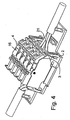
- connection device 1 shows part of a connection device 1 with a base plate 2 and a connection module which can be placed on this base plate or base plate and has a module frame 3, into which a plurality of connection plates 4 can be inserted.
- connection devices each provided with an outer housing with a lid (which will be explained in more detail below) form the higher-level connection system.
- the base frame has a plurality of receiving spaces 6, which are separated from one another by partitions 5 and into which one of the connection disks 4 can be inserted (see FIG. 5).
- the module frame could also, not shown here, be made of a plurality of mutually e.g. consist detent connected single frame, each of which would be designed to receive each one of the connection plates (not shown here).
- connection disks 4 each have - see FIG. 1 as well as FIGS. 6 and 7 - a disc-type base body 7 made of insulating plastic.
- each of the base body 7 are each a insulation piercing first terminal 8 (here a fork contact with overspring 34 - conceivable is also an education as PiercingWallet - and at least one or more hereby connected conductively branching terminals 9 (Fig. 6) for connecting at least one branching conductor (the latter not shown here) arranged.
- the first connection 8 is designed as an insulation-penetrating contact - in this case as a fork contact - (see FIG. 2 b), to which a conductor rail section 10 adjoins, here two of the branch connections 9 are arranged.
- This branch connections 9 can in principle be formed in any connection technique (IDC, screw, spring, etc.). Preference is given to tool-free directly connectable Used spring-loaded contacts 11 (push-in), are arranged for the insertion openings 12 at the top of the base body 7.
- a bus bar 55 of the compression spring contact 11 is adhered to the busbar section 10, wherein the compression spring 56 is disposed on the busbar section 55.
- the further branch connection is formed here as a plug contact 13 in a recess 35 for attaching a connection plug (not shown here). Markers are e.g. can be fixed to the top of the connection discs.
- an actuating device 15 is arranged in each case, with which the connection plates 4 and their base 7 together with the terminals, in particular IDC contacts 8 are displaceable in the base frame, so that the connection Disks 4 are next to the IDC contacts 8 on below the terminal slices arranged conductors 21 are pressed to contact these insulation piercing or to connect.
- these actuators 15 eccentric discs 16. These preferably have an eccentric bearing eye 17.
- slot-like first scenes or slots 18 are further formed in side walls 19 on both sides of the recesses 14, wherein the scenes 18 and the bearing lugs 17 are preferably penetrated by continuous waves 37 (FIG. 1), which in turn preferably through the entire module frame extend and again there pass through openings 36 in the side and intermediate walls of the module frame (see Figs. 1 and 2).
- the slots 18 extend in the direction of actuation or perpendicular to the bottom plate 2, which will be explained in more detail below.
- the shafts 37 could also extend over only one module slot each, but the continuous shaft is more optimal for absorbing power.
- the shafts 37 could also be formed by pins, which are integrally formed on the eccentric discs are (not shown).
- the screwdriver as a preferred operating tool realizes a lever effect for safe wiring.
- the base plate 2 has receptacles 20 (for example five or seven) aligned parallel to one another for the conductors 21 of a cable 22 which has been stripped off in sections, each of which is bounded by two relatively short webs 38 and on two opposite ends of two supports 23 and brackets for the unclipped ends of the cable 22, which also act as strain relief or can be formed.
- These brackets 23 are spaced so far apart that they give the length ofproofzumantelnden area.
- the jacket ends 24 are moved towards each other slightly after stripping, in order to fan out the individual conductors separately from one another into the receptacles 20 (see FIGS. 1 and 6).
- the bottom plate is further provided with fixing means 25 for fixing the module frame to the bottom plate after inserting the conductors.
- These fixing devices 25 are here designed as four snap-in webs which can be latched snapping on the module frame 3, after it has been placed vertically from above onto the bottom plate 2.
- Other types of mounting and fixing are also conceivable (eg, it is conceivable rotatably fix the module frame or the whole preassembled connection module to the bottom plate and then mecanicschwenken on the bottom plate 2 and only one side to lock (see Fig. 5) or it by a screw, a strap or an elastic band or the like.
- On the bottom plate 2 set (not shown)).
- the bottom plate 2 has at least one or more apertures 30 which allow it to be checked that the conductors 21 lie correctly in their receptacles 20. Although here a round cable 22 is shown, a configuration for flat cable is also feasible.
- the cable 22 on which branches are to be installed is stripped in the area between the supports 23. Then, the conductors 21 are fanned out and placed in the receptacles 20 and the cables 22 are placed or clipped in the unshielded area in the formations 23 (Fig. 1).
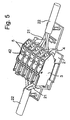
- connection module as a whole, that is to say the module frame 3 with the connecting disks 4 (FIG. 1, FIG. 3) preassembled in it, can be placed on the base plate 2 and fastened to the base plate 2 (FIG 4).
- the connection disks still project upwards out of the module frame 3.
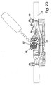
- the eccentric discs 16 are still pivoted with a tool such as a screwdriver 40, which presses the eccentric discs 16 in the recesses 14 and thus the individual connection discs 4 in the module frame 3 down, wherein the below-mentioned IDC contact 8 in the associated Pick inserted conductor 21 contacted (compare Figs. 5, 6 and 7).
- the arrangement is clear and simple and safe to handle, with the eccentric arrangement, which is supported on the module frame, particularly high Bescellens mechanism can be realized.
- the eccentric discs 16 are laterally provided with guide pins 32 which engage in horizontally extending second scenes 33. On the outer circumference, they have an actuating opening 42 in order to be able to pivot with a tool such as a screwdriver 40.
- a tool such as a screwdriver 40.
- As an abutment at the end could also be formed above the eccentric disc 16 is a kind of roof section or a housing web (not shown here).
- a further projection 53 on the eccentric disc 16 is used for engagement in detent holes 54 in the connection disc, to make the loading and the Endscenswolf noticeable and their achievement audible.
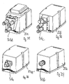
- Fig. 1 it is expedient to arrange the arrangement of Fig. 1 in an over-housing, although it is e.g. can also be used for direct mounting in a control cabinet.
- passage 28 for the cable and openings 28 for outgoing conductors is shown in Fig. 8 ff.
- walls 39 may be formed, which can be separated at predetermined breaking lines 41, to meet a variety of installation situations (Fig. 9).
- a preferably split seal 47 seals the passages or openings for the cable 22.
- the outer housing is universally applicable in a variety of installation situations.
- the outer housing may also be designed to accommodate a plurality of connection systems and modules and, for example, have partitions for this purpose. It is also conceivable to put on a base plate several of the connection modules.
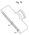
- Fig. 10 shows a closing element 43 for insertion e.g. in the housing of FIG. 8, when it is arranged at the free end of the cable 22, which has a number of chambers 44 corresponding to the number of conductors for inserting the free conductor ends, which are designed such that leakage currents and the like. Safe be avoided.
- a ring shoulder 45 serves for fixing in the holder.
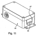
- FIG. 11 An alternative embodiment of a housing 26, which is designed to accommodate a flat cable instead of a round cable (not shown), Fig. 11.
- a flat cable instead of a round cable (not shown)
- Fig. 11 For this purpose, only the seals 47 (preferably fully or partially divided formed) of the outer housing 26 each having a flat opening 48th provided instead of a round opening 49 for the cable 22 (see FIG. 8).
- the receptacles 20 for the conductors 21 are each formed here from two webs 38, which are formed so that in them conductors 21 of different diameters can be used.
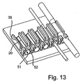
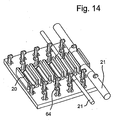
- FIGS. 12 to 15 each show sections of floor panels 2, the remaining areas of which are not shown here for the sake of clarity.
- the webs 38 of the receptacles are each provided with latching hooks 50 for holding or locking the ladder in the recordings.
- latching receptacles 51 are provided in extension of the receptacles, which are formed on a web 52 which is inserted into the base plate or this is attached. This offers the advantage of being able to produce the latching receptacles 51 from a special resilient material, in particular from a different material than the bottom plate.
- FIG. 22 A variant of this embodiment is shown in FIG. 22, in which on both sides of the receptacles 21 separate spring-ring-like latching receptacles 51 are provided which are each formed on one of the webs 52. These are in turn inserted into the bottom plate 2. In this way, the conductors can advantageously be fixed on both sides of the contacting region.
- the locking receptacles 51 can in turn be made of a special resilient material.
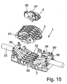
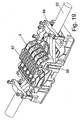
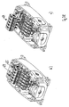
- FIGS. 15 to 22 show a further connection system 1 with the base plate 2 and the connecting module with the module frame which can be placed on this base or base plate 3, in which a plurality of the connection plates 4 can be used.
- the structure of this variant largely corresponds to the structure of the embodiment of FIG. 1 to 8. Analogous elements have the same reference numerals.
- connection disks 4 in turn each have a disk-like basic body 7 made of insulating plastic.
- the insulation-penetrating first terminal 8 is in turn preferably arranged as a forked contact with overspring 34 and at least one or more branching terminals 9 connected thereto for connection of at least one branching conductor.
- the first connection 8 is in turn formed as an insulation-penetrating fork contact (see FIG. 2 b), which is adjoined by the conductor rail section 10, on which two of the branch connections 9 are arranged here.
- the one of the branch connections 9 is in turn here a directly connectable compression spring contact 11 (push-in) used, the busbar 55 is bent directly from the busbar section 10.
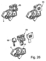
- the further branch connection is also designed here as a plug contact 13 in a recess 35 for attaching a corresponding connection plug 65 (FIGS. 26, 27) to a bushing 66, which according to FIG. 27 also includes electrical / electronic components 67 and / or in turn further Conductor terminals 68 may have.
- the actuators 15 in turn have eccentric discs 16 with the eccentric bearing eye 17.
- the slot-like first scenes or slots 18 are formed in side walls 19 on both sides of the recesses 14, the scenes 18 and the bearing eyes 17 are in turn penetrated by continuous waves 37, which extend through the entire module frame 4 and there again Pass openings 36 in the side and intermediate walls of the module frame (see Figs. 15 and 16).
- the abutment for limit switching is formed here by two housing webs 57 formed above the eccentric disks 16.
- wiring again serves the Base of the recess 14, in which the eccentric disc 16 is arranged, as an abutment to press the terminal plate 4 together with IDC contact 8 on the conductor 21, which is to be contacted.
- the further projection 53 on the eccentric disc 16 also serves again to engage in the detent holes 54 in the connection disc to make the loading and the Endscariaswolf noticeable and their achievement audible.
- the bottom plate is again provided with fixing means 25 to secure the module frame to the bottom plate after inserting the ladder.
- the fixing devices 25 here comprise two snap-on webs 25 which can be latched to the module frame 3 after it has been swung onto the bottom plate on lugs 58 which are realized in a pivot bearing function and which can be inserted into corresponding recesses in the bottom plate 2 (not visible here). This type of installation is particularly easy and safe.
- fixing means are provided here, which are designed as cable clamps 59 with screws 60.
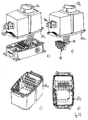
- outer housing with seals 47 for flat or round cables Figs. 24 and 25.
- the outer housing may also be designed to accommodate a plurality of connection systems and modules and, for example, have partitions for this purpose. It is also conceivable here to set up on a correspondingly shaped bottom plate several of the connection modules.
- FIG. 28 illustrates how a plurality of assembled, in particular latched, connection plug 65 can be connected to the plug contacts 13 as a plug strip 69, which in turn are connected to contacts 27 of plug connectors 71 on the cover 27 according to FIG.
- the lid 27a may serve as a mere cover (Figs. 24, 25).
- cover 27c with one or more of the other connectors (or sockets) 71a, 71 b, ... in any number, arrangement and design (eg sensor / actuator, M8, M12, RJ45 with housing, etc. ) (Fig. 29).
- a hinged lid 72 may be formed in order to realize easy access to the electronics (FIG. 30).
- Lid 27 various electrical / electronic components or an entire electronic circuits can be integrated in the lid.
- Lid 27 which accommodates the components of a circuit breaker of any type, a motor protection switch (see FIG. 38) or the like, is particularly suitable here.
- the components of a circuit breaker or a power supply are also integrated into the cover 27, as well as electronics that is required for connection and communication with field devices such as sensors or actuators (eg for connection to a bus system, such as AS-i, preferably an energy and comprising a data bus).
- a bus system such as AS-i, preferably an energy and comprising a data bus.
- distributors for connecting the field devices or, for example, for realizing a star-shaped bus distribution can also be realized with the connection device.
- the cover 271 may be provided according to a variant with cooling fins 73 for heat dissipation to the environment.
- manually operable functional elements such as switches 74 and / or optical displays such as LEDs can be provided on the cover.
- lid 27 with markers and the like. Predictable (not visible here).
Landscapes
- Connections By Means Of Piercing Elements, Nuts, Or Screws (AREA)
- Coupling Device And Connection With Printed Circuit (AREA)
- Connector Housings Or Holding Contact Members (AREA)
- Multi-Conductor Connections (AREA)
Applications Claiming Priority (1)
| Application Number | Priority Date | Filing Date | Title |
|---|---|---|---|
| DE202006015946U DE202006015946U1 (de) | 2006-10-18 | 2006-10-18 | Anschluß-System zur Realisierung von Abzweigungen an durchgehenden Leitern |
Publications (3)
| Publication Number | Publication Date |
|---|---|
| EP1914840A2 true EP1914840A2 (fr) | 2008-04-23 |
| EP1914840A3 EP1914840A3 (fr) | 2009-10-28 |
| EP1914840B1 EP1914840B1 (fr) | 2011-05-11 |
Family
ID=39018048
Family Applications (1)
| Application Number | Title | Priority Date | Filing Date |
|---|---|---|---|
| EP07117037A Active EP1914840B1 (fr) | 2006-10-18 | 2007-09-24 | Système de raccordement destiné à la réalisation d'embranchements sur des lignes continues |
Country Status (4)
| Country | Link |
|---|---|
| US (1) | US7491084B2 (fr) |
| EP (1) | EP1914840B1 (fr) |
| AT (1) | ATE509392T1 (fr) |
| DE (1) | DE202006015946U1 (fr) |
Cited By (4)
| Publication number | Priority date | Publication date | Assignee | Title |
|---|---|---|---|---|
| DE202008015310U1 (de) | 2008-11-19 | 2010-04-08 | Weidmüller Interface GmbH & Co. KG | Baugruppe aus zwei oder mehr Anschlussvorrichtungen zur Realisierung von Abzweigungen an durchgehenden Leitern |
| DE202008015307U1 (de) | 2008-11-19 | 2010-04-08 | Weidmüller Interface GmbH & Co. KG | Anschluss-System zur Realisierung von Abzweigungen an durchgehenden Leitern |
| WO2011138135A1 (fr) * | 2010-05-03 | 2011-11-10 | Siemens Aktiengesellschaft | Ensemble borne pour un appareil électrique |
| DE202010008934U1 (de) | 2010-11-02 | 2012-02-03 | Weidmüller Interface GmbH & Co. KG | Anschluss-System mit Bodenanschluss |
Families Citing this family (11)
| Publication number | Priority date | Publication date | Assignee | Title |
|---|---|---|---|---|
| FR2923659B1 (fr) * | 2007-11-13 | 2009-12-11 | Legrand France | Connecteur a montage facilite pour cable multiconducteur. |
| DE102009042254A1 (de) * | 2009-09-22 | 2011-03-31 | Günther Spelsberg GmbH & Co. KG | Elektrische Anschlussvorrichtung |
| DE202009015913U1 (de) | 2009-11-23 | 2011-05-12 | Weidmüller Interface GmbH & Co. KG | Anschlusssystem zur Realisierung von Abzweigungen an durchgehenden Leitern |
| DE202012105000U1 (de) * | 2012-12-20 | 2014-03-21 | Weidmüller Interface GmbH & Co. KG | Kabelanschluss , insbesondere für einen Anschlussstecker |
| US9396889B1 (en) * | 2015-04-03 | 2016-07-19 | Eaton Corporation | Electrical switching apparatus and secondary disconnect assembly with cradle assembly alignment and positioning features therefor |
| JP6652574B2 (ja) * | 2015-04-09 | 2020-02-26 | フェニックス コンタクト ディベロップメント アンド マニュファクチャリング、インコーポレイテッド | 電子モジュール抽出フィードバックシステム |
| US9419353B1 (en) * | 2016-02-25 | 2016-08-16 | Daoud S. Al-Saqabi | Electrical wire connection strip |
| US10211582B1 (en) * | 2017-08-10 | 2019-02-19 | Te Connectivity Corporation | Bus bar clamp |
| CN109560436B (zh) * | 2017-09-26 | 2024-02-02 | 安波福中央电气(上海)有限公司 | 电连接器 |
| DE102019105693A1 (de) * | 2019-03-06 | 2020-09-10 | HARTING Customised Solutions GmbH & Co. KG | Verteilergehäuse |
| US10971864B1 (en) * | 2019-09-30 | 2021-04-06 | BAKC Capital Group | DIN rail shield |
Citations (3)
| Publication number | Priority date | Publication date | Assignee | Title |
|---|---|---|---|---|
| DE29706750U1 (de) | 1997-04-15 | 1997-05-28 | Ackermann Albert Gmbh Co | Anschlußvorrichtung für elektrische Flachkabel |
| DE29708222U1 (de) | 1997-05-07 | 1998-09-10 | Tehalit Gmbh | Anschlußvorrichtung für Flachkabel |
| DE19903030C1 (de) | 1999-01-26 | 2001-05-03 | Siemens Ag | Vorrichtung zur abisolierfreien Kontaktierung eines Flachkabels |
Family Cites Families (10)
| Publication number | Priority date | Publication date | Assignee | Title |
|---|---|---|---|---|
| US5635001A (en) * | 1994-03-18 | 1997-06-03 | Specialty Adhesive Film Co. | Twill decorative and method of applying |
| US5553136A (en) * | 1994-05-19 | 1996-09-03 | Tii Industries, Inc. | Modular device for telephone network interface apparatus |
| DE29905025U1 (de) * | 1999-03-19 | 1999-06-02 | Weidmueller Interface | Verteiler zum Verbinden von Aktoren und/oder Sensoren |
| ATE397307T1 (de) * | 1999-09-20 | 2008-06-15 | Woertz Ag | Kontaktierungsvorrichtung für ein flachbandkabel |
| KR100469735B1 (ko) * | 2000-07-18 | 2005-02-02 | 삼성전자주식회사 | 부호분할다중접속 이동통신시스템의 호 수용방법 |
| US6631269B1 (en) * | 2002-05-23 | 2003-10-07 | Interdigital Technology Corporation | Signaling connection admission control in a wireless network |
| US6944461B2 (en) * | 2002-06-03 | 2005-09-13 | Lucent Technologies Inc. | Communication system and method for quality-based call admission control and scheduling |
| US7136656B2 (en) * | 2003-03-20 | 2006-11-14 | Interdigital Technology Corporation | Method of fast dynamic channel allocation call admission control for radio link addition in radio resource management |
| DE202005014718U1 (de) * | 2005-09-17 | 2007-02-01 | Weidmüller Interface GmbH & Co. KG | Anschluß-System zur Realisierung von Abzweigungen an durchgehenden Leitern |
| DE202005014719U1 (de) * | 2005-09-17 | 2007-02-01 | Weidmüller Interface GmbH & Co. KG | Anschluß-System zur Realisierung von Abzweigungen an durchgehenden Leitern |
-
2006
- 2006-10-18 DE DE202006015946U patent/DE202006015946U1/de not_active Expired - Lifetime
-
2007
- 2007-09-24 AT AT07117037T patent/ATE509392T1/de active
- 2007-09-24 EP EP07117037A patent/EP1914840B1/fr active Active
- 2007-10-16 US US11/974,830 patent/US7491084B2/en active Active
Patent Citations (3)
| Publication number | Priority date | Publication date | Assignee | Title |
|---|---|---|---|---|
| DE29706750U1 (de) | 1997-04-15 | 1997-05-28 | Ackermann Albert Gmbh Co | Anschlußvorrichtung für elektrische Flachkabel |
| DE29708222U1 (de) | 1997-05-07 | 1998-09-10 | Tehalit Gmbh | Anschlußvorrichtung für Flachkabel |
| DE19903030C1 (de) | 1999-01-26 | 2001-05-03 | Siemens Ag | Vorrichtung zur abisolierfreien Kontaktierung eines Flachkabels |
Cited By (7)
| Publication number | Priority date | Publication date | Assignee | Title |
|---|---|---|---|---|
| DE202008015310U1 (de) | 2008-11-19 | 2010-04-08 | Weidmüller Interface GmbH & Co. KG | Baugruppe aus zwei oder mehr Anschlussvorrichtungen zur Realisierung von Abzweigungen an durchgehenden Leitern |
| DE202008015307U1 (de) | 2008-11-19 | 2010-04-08 | Weidmüller Interface GmbH & Co. KG | Anschluss-System zur Realisierung von Abzweigungen an durchgehenden Leitern |
| WO2010057750A2 (fr) * | 2008-11-19 | 2010-05-27 | Weidmüller Interface GmbH & Co. KG | Agencement composé de deux dispositifs de raccordement ou plus destinés à réaliser des dérivations sur des conducteurs continus |
| WO2010057750A3 (fr) * | 2008-11-19 | 2011-05-12 | Weidmüller Interface GmbH & Co. KG | Agencement composé de deux dispositifs de raccordement ou plus destinés à réaliser des dérivations sur des conducteurs continus |
| US8298019B2 (en) | 2008-11-19 | 2012-10-30 | Weidmueller Interface Gmbh & Co. Kg | Connecting system for implementing branches on continuous conductors |
| WO2011138135A1 (fr) * | 2010-05-03 | 2011-11-10 | Siemens Aktiengesellschaft | Ensemble borne pour un appareil électrique |
| DE202010008934U1 (de) | 2010-11-02 | 2012-02-03 | Weidmüller Interface GmbH & Co. KG | Anschluss-System mit Bodenanschluss |
Also Published As
| Publication number | Publication date |
|---|---|
| EP1914840A3 (fr) | 2009-10-28 |
| ATE509392T1 (de) | 2011-05-15 |
| US7491084B2 (en) | 2009-02-17 |
| DE202006015946U1 (de) | 2008-02-28 |
| US20080096416A1 (en) | 2008-04-24 |
| EP1914840B1 (fr) | 2011-05-11 |
Similar Documents
| Publication | Publication Date | Title |
|---|---|---|
| EP1914840B1 (fr) | Système de raccordement destiné à la réalisation d'embranchements sur des lignes continues | |
| EP1764870B1 (fr) | Système de connexion pour réalisation des branchements des conducteurs continus | |
| EP2005486B1 (fr) | Dispositif de connexion électrique pour conducteurs plats | |
| EP1764871B1 (fr) | Système de connexion pour réalisation des branchements des conducteurs continus | |
| EP0882318B1 (fr) | Connecteur electrique multiple multipolaire et partie de douille associee | |
| EP2351154B1 (fr) | Agencement de bornes en série avec raccordements transversaux et connecteurs d'essai | |
| EP1022809A2 (fr) | Appareil électrique | |
| EP0909122B1 (fr) | Appareil électrique | |
| EP2554030A1 (fr) | Module de raccordement compatible bus | |
| DE19902745B4 (de) | Elektrisches Gerät | |
| EP3275049B2 (fr) | Ensemble de serrage, borne à ressort et interrupteur comprenant cet ensemble de serrage | |
| DE202014100115U1 (de) | Anordnung mit einem Modul und einer Elektronikanordnung | |
| EP0702441B1 (fr) | Appareillage d'installation électrique, notamment pour canalisations de câbles | |
| WO2010057749A1 (fr) | Système de raccordement pour réaliser des branchements sur des conducteurs continus | |
| EP2497169A2 (fr) | Agencement de montage pour appareils électriques | |
| EP1388914B1 (fr) | Système de raccordement | |
| EP0813269B1 (fr) | Connecteur électrique | |
| DE102014109984A1 (de) | Elektronikgeräteanordnung | |
| EP3117487B1 (fr) | Dispositif de protection contre les surtensions comprenant au moins un appareil de protection contre les surtensions | |
| DE102013017157B4 (de) | Vorrichtung zur Montage mindestens eines als Steckmodul ausgebildeten Überspannungsschutzgeräts | |
| DE19816391C2 (de) | Türstation einer Türsprechanlage | |
| DE10146503A1 (de) | Elektrische Installationsverteilung | |
| EP1039606B1 (fr) | Dispositif pour connecter électriquement au moins deux appareils electriques | |
| EP1037474B1 (fr) | Appareil électronique, en particulier un central téléphonique | |
| DE10130299A1 (de) | Elektrische Mehrfachsteckdoseneinheit |
Legal Events
| Date | Code | Title | Description |
|---|---|---|---|
| PUAI | Public reference made under article 153(3) epc to a published international application that has entered the european phase |
Free format text: ORIGINAL CODE: 0009012 |
|
| AK | Designated contracting states |
Kind code of ref document: A2 Designated state(s): AT BE BG CH CY CZ DE DK EE ES FI FR GB GR HU IE IS IT LI LT LU LV MC MT NL PL PT RO SE SI SK TR |
|
| AX | Request for extension of the european patent |
Extension state: AL BA HR MK RS |
|
| PUAL | Search report despatched |
Free format text: ORIGINAL CODE: 0009013 |
|
| AK | Designated contracting states |
Kind code of ref document: A3 Designated state(s): AT BE BG CH CY CZ DE DK EE ES FI FR GB GR HU IE IS IT LI LT LU LV MC MT NL PL PT RO SE SI SK TR |
|
| AX | Request for extension of the european patent |
Extension state: AL BA HR MK RS |
|
| 17P | Request for examination filed |
Effective date: 20100331 |
|
| 17Q | First examination report despatched |
Effective date: 20100429 |
|
| AKX | Designation fees paid |
Designated state(s): AT BE BG CH CY CZ DE DK EE ES FI FR GB GR HU IE IS IT LI LT LU LV MC MT NL PL PT RO SE SI SK TR |
|
| GRAP | Despatch of communication of intention to grant a patent |
Free format text: ORIGINAL CODE: EPIDOSNIGR1 |
|
| GRAS | Grant fee paid |
Free format text: ORIGINAL CODE: EPIDOSNIGR3 |
|
| GRAA | (expected) grant |
Free format text: ORIGINAL CODE: 0009210 |
|
| AK | Designated contracting states |
Kind code of ref document: B1 Designated state(s): AT BE BG CH CY CZ DE DK EE ES FI FR GB GR HU IE IS IT LI LT LU LV MC MT NL PL PT RO SE SI SK TR |
|
| REG | Reference to a national code |
Ref country code: GB Ref legal event code: FG4D Free format text: NOT ENGLISH |
|
| REG | Reference to a national code |
Ref country code: CH Ref legal event code: EP |
|
| REG | Reference to a national code |
Ref country code: IE Ref legal event code: FG4D |
|
| REG | Reference to a national code |
Ref country code: DE Ref legal event code: R096 Ref document number: 502007007164 Country of ref document: DE Effective date: 20110622 |
|
| REG | Reference to a national code |
Ref country code: NL Ref legal event code: VDEP Effective date: 20110511 |
|
| PG25 | Lapsed in a contracting state [announced via postgrant information from national office to epo] |
Ref country code: PT Free format text: LAPSE BECAUSE OF FAILURE TO SUBMIT A TRANSLATION OF THE DESCRIPTION OR TO PAY THE FEE WITHIN THE PRESCRIBED TIME-LIMIT Effective date: 20110912 Ref country code: SE Free format text: LAPSE BECAUSE OF FAILURE TO SUBMIT A TRANSLATION OF THE DESCRIPTION OR TO PAY THE FEE WITHIN THE PRESCRIBED TIME-LIMIT Effective date: 20110511 Ref country code: LT Free format text: LAPSE BECAUSE OF FAILURE TO SUBMIT A TRANSLATION OF THE DESCRIPTION OR TO PAY THE FEE WITHIN THE PRESCRIBED TIME-LIMIT Effective date: 20110511 |
|
| PG25 | Lapsed in a contracting state [announced via postgrant information from national office to epo] |
Ref country code: LV Free format text: LAPSE BECAUSE OF FAILURE TO SUBMIT A TRANSLATION OF THE DESCRIPTION OR TO PAY THE FEE WITHIN THE PRESCRIBED TIME-LIMIT Effective date: 20110511 Ref country code: ES Free format text: LAPSE BECAUSE OF FAILURE TO SUBMIT A TRANSLATION OF THE DESCRIPTION OR TO PAY THE FEE WITHIN THE PRESCRIBED TIME-LIMIT Effective date: 20110822 Ref country code: SI Free format text: LAPSE BECAUSE OF FAILURE TO SUBMIT A TRANSLATION OF THE DESCRIPTION OR TO PAY THE FEE WITHIN THE PRESCRIBED TIME-LIMIT Effective date: 20110511 Ref country code: GR Free format text: LAPSE BECAUSE OF FAILURE TO SUBMIT A TRANSLATION OF THE DESCRIPTION OR TO PAY THE FEE WITHIN THE PRESCRIBED TIME-LIMIT Effective date: 20110812 Ref country code: IS Free format text: LAPSE BECAUSE OF FAILURE TO SUBMIT A TRANSLATION OF THE DESCRIPTION OR TO PAY THE FEE WITHIN THE PRESCRIBED TIME-LIMIT Effective date: 20110911 Ref country code: FI Free format text: LAPSE BECAUSE OF FAILURE TO SUBMIT A TRANSLATION OF THE DESCRIPTION OR TO PAY THE FEE WITHIN THE PRESCRIBED TIME-LIMIT Effective date: 20110511 Ref country code: CY Free format text: LAPSE BECAUSE OF FAILURE TO SUBMIT A TRANSLATION OF THE DESCRIPTION OR TO PAY THE FEE WITHIN THE PRESCRIBED TIME-LIMIT Effective date: 20110511 |
|
| REG | Reference to a national code |
Ref country code: IE Ref legal event code: FD4D |
|
| PG25 | Lapsed in a contracting state [announced via postgrant information from national office to epo] |
Ref country code: NL Free format text: LAPSE BECAUSE OF FAILURE TO SUBMIT A TRANSLATION OF THE DESCRIPTION OR TO PAY THE FEE WITHIN THE PRESCRIBED TIME-LIMIT Effective date: 20110511 |
|
| PG25 | Lapsed in a contracting state [announced via postgrant information from national office to epo] |
Ref country code: EE Free format text: LAPSE BECAUSE OF FAILURE TO SUBMIT A TRANSLATION OF THE DESCRIPTION OR TO PAY THE FEE WITHIN THE PRESCRIBED TIME-LIMIT Effective date: 20110511 Ref country code: CZ Free format text: LAPSE BECAUSE OF FAILURE TO SUBMIT A TRANSLATION OF THE DESCRIPTION OR TO PAY THE FEE WITHIN THE PRESCRIBED TIME-LIMIT Effective date: 20110511 Ref country code: IE Free format text: LAPSE BECAUSE OF FAILURE TO SUBMIT A TRANSLATION OF THE DESCRIPTION OR TO PAY THE FEE WITHIN THE PRESCRIBED TIME-LIMIT Effective date: 20110511 |
|
| PG25 | Lapsed in a contracting state [announced via postgrant information from national office to epo] |
Ref country code: DK Free format text: LAPSE BECAUSE OF FAILURE TO SUBMIT A TRANSLATION OF THE DESCRIPTION OR TO PAY THE FEE WITHIN THE PRESCRIBED TIME-LIMIT Effective date: 20110511 Ref country code: RO Free format text: LAPSE BECAUSE OF FAILURE TO SUBMIT A TRANSLATION OF THE DESCRIPTION OR TO PAY THE FEE WITHIN THE PRESCRIBED TIME-LIMIT Effective date: 20110511 Ref country code: SK Free format text: LAPSE BECAUSE OF FAILURE TO SUBMIT A TRANSLATION OF THE DESCRIPTION OR TO PAY THE FEE WITHIN THE PRESCRIBED TIME-LIMIT Effective date: 20110511 Ref country code: PL Free format text: LAPSE BECAUSE OF FAILURE TO SUBMIT A TRANSLATION OF THE DESCRIPTION OR TO PAY THE FEE WITHIN THE PRESCRIBED TIME-LIMIT Effective date: 20110511 |
|
| PLBE | No opposition filed within time limit |
Free format text: ORIGINAL CODE: 0009261 |
|
| STAA | Information on the status of an ep patent application or granted ep patent |
Free format text: STATUS: NO OPPOSITION FILED WITHIN TIME LIMIT |
|
| BERE | Be: lapsed |
Owner name: WEIDMULLER INTERFACE G.M.B.H. & CO. KG Effective date: 20110930 |
|
| 26N | No opposition filed |
Effective date: 20120214 |
|
| PG25 | Lapsed in a contracting state [announced via postgrant information from national office to epo] |
Ref country code: MC Free format text: LAPSE BECAUSE OF NON-PAYMENT OF DUE FEES Effective date: 20110930 |
|
| REG | Reference to a national code |
Ref country code: CH Ref legal event code: PL |
|
| GBPC | Gb: european patent ceased through non-payment of renewal fee |
Effective date: 20110924 |
|
| REG | Reference to a national code |
Ref country code: DE Ref legal event code: R097 Ref document number: 502007007164 Country of ref document: DE Effective date: 20120214 |
|
| PG25 | Lapsed in a contracting state [announced via postgrant information from national office to epo] |
Ref country code: BE Free format text: LAPSE BECAUSE OF NON-PAYMENT OF DUE FEES Effective date: 20110930 |
|
| PG25 | Lapsed in a contracting state [announced via postgrant information from national office to epo] |
Ref country code: LI Free format text: LAPSE BECAUSE OF NON-PAYMENT OF DUE FEES Effective date: 20110930 Ref country code: CH Free format text: LAPSE BECAUSE OF NON-PAYMENT OF DUE FEES Effective date: 20110930 |
|
| PG25 | Lapsed in a contracting state [announced via postgrant information from national office to epo] |
Ref country code: GB Free format text: LAPSE BECAUSE OF NON-PAYMENT OF DUE FEES Effective date: 20110924 |
|
| PG25 | Lapsed in a contracting state [announced via postgrant information from national office to epo] |
Ref country code: MT Free format text: LAPSE BECAUSE OF FAILURE TO SUBMIT A TRANSLATION OF THE DESCRIPTION OR TO PAY THE FEE WITHIN THE PRESCRIBED TIME-LIMIT Effective date: 20110511 |
|
| PG25 | Lapsed in a contracting state [announced via postgrant information from national office to epo] |
Ref country code: LU Free format text: LAPSE BECAUSE OF NON-PAYMENT OF DUE FEES Effective date: 20110924 |
|
| PG25 | Lapsed in a contracting state [announced via postgrant information from national office to epo] |
Ref country code: BG Free format text: LAPSE BECAUSE OF FAILURE TO SUBMIT A TRANSLATION OF THE DESCRIPTION OR TO PAY THE FEE WITHIN THE PRESCRIBED TIME-LIMIT Effective date: 20110811 |
|
| PG25 | Lapsed in a contracting state [announced via postgrant information from national office to epo] |
Ref country code: TR Free format text: LAPSE BECAUSE OF FAILURE TO SUBMIT A TRANSLATION OF THE DESCRIPTION OR TO PAY THE FEE WITHIN THE PRESCRIBED TIME-LIMIT Effective date: 20110511 |
|
| PG25 | Lapsed in a contracting state [announced via postgrant information from national office to epo] |
Ref country code: HU Free format text: LAPSE BECAUSE OF FAILURE TO SUBMIT A TRANSLATION OF THE DESCRIPTION OR TO PAY THE FEE WITHIN THE PRESCRIBED TIME-LIMIT Effective date: 20110511 |
|
| REG | Reference to a national code |
Ref country code: FR Ref legal event code: PLFP Year of fee payment: 10 |
|
| REG | Reference to a national code |
Ref country code: FR Ref legal event code: PLFP Year of fee payment: 11 |
|
| REG | Reference to a national code |
Ref country code: FR Ref legal event code: PLFP Year of fee payment: 12 |
|
| PGFP | Annual fee paid to national office [announced via postgrant information from national office to epo] |
Ref country code: IT Payment date: 20190925 Year of fee payment: 13 Ref country code: FR Payment date: 20190926 Year of fee payment: 13 |
|
| PGFP | Annual fee paid to national office [announced via postgrant information from national office to epo] |
Ref country code: AT Payment date: 20190919 Year of fee payment: 13 |
|
| REG | Reference to a national code |
Ref country code: AT Ref legal event code: MM01 Ref document number: 509392 Country of ref document: AT Kind code of ref document: T Effective date: 20200924 |
|
| PG25 | Lapsed in a contracting state [announced via postgrant information from national office to epo] |
Ref country code: FR Free format text: LAPSE BECAUSE OF NON-PAYMENT OF DUE FEES Effective date: 20200930 |
|
| PG25 | Lapsed in a contracting state [announced via postgrant information from national office to epo] |
Ref country code: AT Free format text: LAPSE BECAUSE OF NON-PAYMENT OF DUE FEES Effective date: 20200924 |
|
| PG25 | Lapsed in a contracting state [announced via postgrant information from national office to epo] |
Ref country code: IT Free format text: LAPSE BECAUSE OF NON-PAYMENT OF DUE FEES Effective date: 20200924 |
|
| P01 | Opt-out of the competence of the unified patent court (upc) registered |
Effective date: 20230524 |
|
| PGFP | Annual fee paid to national office [announced via postgrant information from national office to epo] |
Ref country code: DE Payment date: 20230920 Year of fee payment: 17 |