EP1914492A2 - High pressure regulation in a transcritical vapor compression cycle - Google Patents
High pressure regulation in a transcritical vapor compression cycle Download PDFInfo
- Publication number
- EP1914492A2 EP1914492A2 EP07024776A EP07024776A EP1914492A2 EP 1914492 A2 EP1914492 A2 EP 1914492A2 EP 07024776 A EP07024776 A EP 07024776A EP 07024776 A EP07024776 A EP 07024776A EP 1914492 A2 EP1914492 A2 EP 1914492A2
- Authority
- EP
- European Patent Office
- Prior art keywords
- flash tank
- charge
- refrigerant
- high pressure
- valve
- Prior art date
- Legal status (The legal status is an assumption and is not a legal conclusion. Google has not performed a legal analysis and makes no representation as to the accuracy of the status listed.)
- Granted
Links
Images


Classifications
-
- F—MECHANICAL ENGINEERING; LIGHTING; HEATING; WEAPONS; BLASTING
- F25—REFRIGERATION OR COOLING; COMBINED HEATING AND REFRIGERATION SYSTEMS; HEAT PUMP SYSTEMS; MANUFACTURE OR STORAGE OF ICE; LIQUEFACTION SOLIDIFICATION OF GASES
- F25B—REFRIGERATION MACHINES, PLANTS OR SYSTEMS; COMBINED HEATING AND REFRIGERATION SYSTEMS; HEAT PUMP SYSTEMS
- F25B9/00—Compression machines, plants or systems, in which the refrigerant is air or other gas of low boiling point
- F25B9/002—Compression machines, plants or systems, in which the refrigerant is air or other gas of low boiling point characterised by the refrigerant
- F25B9/008—Compression machines, plants or systems, in which the refrigerant is air or other gas of low boiling point characterised by the refrigerant the refrigerant being carbon dioxide
-
- F—MECHANICAL ENGINEERING; LIGHTING; HEATING; WEAPONS; BLASTING
- F25—REFRIGERATION OR COOLING; COMBINED HEATING AND REFRIGERATION SYSTEMS; HEAT PUMP SYSTEMS; MANUFACTURE OR STORAGE OF ICE; LIQUEFACTION SOLIDIFICATION OF GASES
- F25B—REFRIGERATION MACHINES, PLANTS OR SYSTEMS; COMBINED HEATING AND REFRIGERATION SYSTEMS; HEAT PUMP SYSTEMS
- F25B1/00—Compression machines, plants or systems with non-reversible cycle
- F25B1/10—Compression machines, plants or systems with non-reversible cycle with multi-stage compression
-
- F—MECHANICAL ENGINEERING; LIGHTING; HEATING; WEAPONS; BLASTING
- F25—REFRIGERATION OR COOLING; COMBINED HEATING AND REFRIGERATION SYSTEMS; HEAT PUMP SYSTEMS; MANUFACTURE OR STORAGE OF ICE; LIQUEFACTION SOLIDIFICATION OF GASES
- F25B—REFRIGERATION MACHINES, PLANTS OR SYSTEMS; COMBINED HEATING AND REFRIGERATION SYSTEMS; HEAT PUMP SYSTEMS
- F25B41/00—Fluid-circulation arrangements
- F25B41/30—Expansion means; Dispositions thereof
- F25B41/39—Dispositions with two or more expansion means arranged in series, i.e. multi-stage expansion, on a refrigerant line leading to the same evaporator
-
- F—MECHANICAL ENGINEERING; LIGHTING; HEATING; WEAPONS; BLASTING
- F25—REFRIGERATION OR COOLING; COMBINED HEATING AND REFRIGERATION SYSTEMS; HEAT PUMP SYSTEMS; MANUFACTURE OR STORAGE OF ICE; LIQUEFACTION SOLIDIFICATION OF GASES
- F25B—REFRIGERATION MACHINES, PLANTS OR SYSTEMS; COMBINED HEATING AND REFRIGERATION SYSTEMS; HEAT PUMP SYSTEMS
- F25B5/00—Compression machines, plants or systems, with several evaporator circuits, e.g. for varying refrigerating capacity
- F25B5/04—Compression machines, plants or systems, with several evaporator circuits, e.g. for varying refrigerating capacity arranged in series
-
- F—MECHANICAL ENGINEERING; LIGHTING; HEATING; WEAPONS; BLASTING
- F25—REFRIGERATION OR COOLING; COMBINED HEATING AND REFRIGERATION SYSTEMS; HEAT PUMP SYSTEMS; MANUFACTURE OR STORAGE OF ICE; LIQUEFACTION SOLIDIFICATION OF GASES
- F25B—REFRIGERATION MACHINES, PLANTS OR SYSTEMS; COMBINED HEATING AND REFRIGERATION SYSTEMS; HEAT PUMP SYSTEMS
- F25B2309/00—Gas cycle refrigeration machines
- F25B2309/06—Compression machines, plants or systems characterised by the refrigerant being carbon dioxide
- F25B2309/061—Compression machines, plants or systems characterised by the refrigerant being carbon dioxide with cycle highest pressure above the supercritical pressure
-
- F—MECHANICAL ENGINEERING; LIGHTING; HEATING; WEAPONS; BLASTING
- F25—REFRIGERATION OR COOLING; COMBINED HEATING AND REFRIGERATION SYSTEMS; HEAT PUMP SYSTEMS; MANUFACTURE OR STORAGE OF ICE; LIQUEFACTION SOLIDIFICATION OF GASES
- F25B—REFRIGERATION MACHINES, PLANTS OR SYSTEMS; COMBINED HEATING AND REFRIGERATION SYSTEMS; HEAT PUMP SYSTEMS
- F25B2400/00—Component parts or details not otherwise provided for in this subclass
- F25B2400/13—Economisers
-
- F—MECHANICAL ENGINEERING; LIGHTING; HEATING; WEAPONS; BLASTING
- F25—REFRIGERATION OR COOLING; COMBINED HEATING AND REFRIGERATION SYSTEMS; HEAT PUMP SYSTEMS; MANUFACTURE OR STORAGE OF ICE; LIQUEFACTION SOLIDIFICATION OF GASES
- F25B—REFRIGERATION MACHINES, PLANTS OR SYSTEMS; COMBINED HEATING AND REFRIGERATION SYSTEMS; HEAT PUMP SYSTEMS
- F25B2400/00—Component parts or details not otherwise provided for in this subclass
- F25B2400/16—Receivers
-
- F—MECHANICAL ENGINEERING; LIGHTING; HEATING; WEAPONS; BLASTING
- F25—REFRIGERATION OR COOLING; COMBINED HEATING AND REFRIGERATION SYSTEMS; HEAT PUMP SYSTEMS; MANUFACTURE OR STORAGE OF ICE; LIQUEFACTION SOLIDIFICATION OF GASES
- F25B—REFRIGERATION MACHINES, PLANTS OR SYSTEMS; COMBINED HEATING AND REFRIGERATION SYSTEMS; HEAT PUMP SYSTEMS
- F25B2400/00—Component parts or details not otherwise provided for in this subclass
- F25B2400/23—Separators
-
- F—MECHANICAL ENGINEERING; LIGHTING; HEATING; WEAPONS; BLASTING
- F25—REFRIGERATION OR COOLING; COMBINED HEATING AND REFRIGERATION SYSTEMS; HEAT PUMP SYSTEMS; MANUFACTURE OR STORAGE OF ICE; LIQUEFACTION SOLIDIFICATION OF GASES
- F25B—REFRIGERATION MACHINES, PLANTS OR SYSTEMS; COMBINED HEATING AND REFRIGERATION SYSTEMS; HEAT PUMP SYSTEMS
- F25B2600/00—Control issues
- F25B2600/05—Refrigerant levels
-
- F—MECHANICAL ENGINEERING; LIGHTING; HEATING; WEAPONS; BLASTING
- F25—REFRIGERATION OR COOLING; COMBINED HEATING AND REFRIGERATION SYSTEMS; HEAT PUMP SYSTEMS; MANUFACTURE OR STORAGE OF ICE; LIQUEFACTION SOLIDIFICATION OF GASES
- F25B—REFRIGERATION MACHINES, PLANTS OR SYSTEMS; COMBINED HEATING AND REFRIGERATION SYSTEMS; HEAT PUMP SYSTEMS
- F25B2600/00—Control issues
- F25B2600/17—Control issues by controlling the pressure of the condenser
-
- F—MECHANICAL ENGINEERING; LIGHTING; HEATING; WEAPONS; BLASTING
- F25—REFRIGERATION OR COOLING; COMBINED HEATING AND REFRIGERATION SYSTEMS; HEAT PUMP SYSTEMS; MANUFACTURE OR STORAGE OF ICE; LIQUEFACTION SOLIDIFICATION OF GASES
- F25B—REFRIGERATION MACHINES, PLANTS OR SYSTEMS; COMBINED HEATING AND REFRIGERATION SYSTEMS; HEAT PUMP SYSTEMS
- F25B2600/00—Control issues
- F25B2600/25—Control of valves
- F25B2600/2509—Economiser valves
-
- F—MECHANICAL ENGINEERING; LIGHTING; HEATING; WEAPONS; BLASTING
- F25—REFRIGERATION OR COOLING; COMBINED HEATING AND REFRIGERATION SYSTEMS; HEAT PUMP SYSTEMS; MANUFACTURE OR STORAGE OF ICE; LIQUEFACTION SOLIDIFICATION OF GASES
- F25B—REFRIGERATION MACHINES, PLANTS OR SYSTEMS; COMBINED HEATING AND REFRIGERATION SYSTEMS; HEAT PUMP SYSTEMS
- F25B2600/00—Control issues
- F25B2600/25—Control of valves
- F25B2600/2513—Expansion valves
-
- F—MECHANICAL ENGINEERING; LIGHTING; HEATING; WEAPONS; BLASTING
- F25—REFRIGERATION OR COOLING; COMBINED HEATING AND REFRIGERATION SYSTEMS; HEAT PUMP SYSTEMS; MANUFACTURE OR STORAGE OF ICE; LIQUEFACTION SOLIDIFICATION OF GASES
- F25B—REFRIGERATION MACHINES, PLANTS OR SYSTEMS; COMBINED HEATING AND REFRIGERATION SYSTEMS; HEAT PUMP SYSTEMS
- F25B31/00—Compressor arrangements
- F25B31/006—Cooling of compressor or motor
- F25B31/008—Cooling of compressor or motor by injecting a liquid
Definitions
- the present invention relates generally to a means for regulating the high pressure component of a transcritical vapor compression system.
- Chlorine containing refrigerants have been phased out in most of the world due to their ozone destroying potential.
- Hydrofluoro carbons HFCs
- Natural refrigerants such as carbon dioxide and propane, have been proposed as replacement fluids. Unfortunately, there are problems with the use of many of these fluids as well.
- Carbon dioxide has a low critical point, which causes most air conditioning systems utilizing carbon dioxide as a refrigerant to run transcritical under most conditions.
- the present invention relates to a means for regulating the high pressure component of a transcritical vapor compression system.
- a vapor compression system consists of a compressor, a gas cooler, an expansion device, and an evaporator.
- Economizer cycles are sometimes employed to increase the efficiency and/or capacity of the system.
- Economizer cycles operate by expanding the refrigerant leaving the heat rejecting heat exchanger to an intermediate pressure and separating the refrigerant flow into two streams. One stream is sent to the heat absorbing heat exchanger, and the other is sent to cool the flow between two compression stages.
- a flash tank is used to perform the separation. This invention regulates the high pressure component of the vapor compression system (pressure in the gas cooler) by controlling the amount of charge in the flash tank.
- carbon dioxide is used as the refrigerant.
- refrigerant discharged from the gas cooler passes through a first expansion device, and its pressure is reduced.
- the refrigerant collects in the flash tank as part liquid and part vapor.
- the vapor refrigerant is used to cool refrigerant exhaust as it exits a first compression device, and the liquid refrigerant is further expanded by a second expansion device before entering the evaporator.
- Expansion valves positioned on the path leading into and out of the flash tank arc used to expand the refrigerant from high pressure to low pressure.
- This invention controls the actuation of the expansion valves to control the flow of charge into and out of the flash tank, regulating the amount of charge stored in the flash tank. By regulating the amount of charge stored in the flash tank, the amount of charge in the gas cooler and the high pressure of the system can be controlled.
- An optimal pressure of the system can be selected by controlling the actuation of the valves. If the pressure in the gas cooler is too low, the expansion valves can be adjusted to release charge from the flash tank into the system to increase the gas cooler pressure, increasing the capacity of the system. If the pressure in the gas cooler is too high, the expansion valves can be adjusted to store charge in the flash tank to decrease the gas cooler pressure, reducing the energy expended by the compressor.
- the present invention provides a method and system for regulating the high pressure component of a transcritical vapor compression system.
- an apparatus for regulating a high pressure of a refrigerant circulating in a transcritical vapor compression system comprising:
- a transcritical vapor compression system comprising:
- the high pressure is regulated by actuating said first expansion valve and said second expansion valve to control said amount of charge in said flash tank.
- the charge is preferably stored in said flash tank to decrease said high pressure of said refrigerant and is released from said flash tank to increase said high pressure of said refrigerant.
- the first and second expansion valves can be controlled to decrease said charge in said flash tank and to increase said high pressure of said refrigerant. Furthermore, the first and second expansion valves can preferably be controlled to increase said charge in said flash tank and to decrease said high pressure of said refrigerant.
- a third valve is positioned to regulate flow of said charge from said flash tank to a or said heat accepting heat exchanger and a fourth valve is positioned to regulate flow of said charge from said flash tank to a or the compression device, said third valve and said fourth valve actuated by a controller monitoring said high pressure.
- the refrigerant is carbon dioxide.
- a method of regulating a high pressure of a refrigerant in a transcritical vapor compression system by regulating an amount of charge in a flash tank comprising the steps of:
- Refrigerant is circulated though the closed circuit cycle 10.
- carbon dioxide is used as the refrigerant. While carbon dioxide is illustrated, other refrigerants may be used. Because carbon dioxide has a low critical point, systems utilizing carbon dioxide as a refrigerant usually require the vapor compression system 10 to run transcritical.
- the system 10 When the system 10 is run transcritical, it is advantageous to regulate the high pressure component of the vapor compression system 10.
- the capacity and/or efficiency of the system 10 can be controlled and optimized.
- Increasing the gas cooler 14 pressure lowers the enthalpy entering the evaporator 18 and increases capacity, but also requires more energy because the compressor 16 must work harder.
- the optimal pressure of the system 10 which changes as the operating conditions change, can be selected.
- the refrigerant exits the compressor 12 at high pressure and enthalpy, shown by point A in Figure 2 .
- the refrigerant flows through the gas cooler 14 at high pressure, it loses heat and enthalpy, exiting the gas cooler 14 with low enthalpy and high pressure, indicated as point B.
- the pressure of the refrigerant drops, shown by point C.
- the refrigerant passes through the evaporator 18 and exits at a high enthalpy and low pressure, represented by point D.
- the refrigerant passes through the compressor 12, it is again at high pressure and enthalpy, completing the cycle.
- FIG 3 illustrates a vapor compression system 10 employing a flash tank 20 in a two stage economized cycle.
- the refrigerant exiting the gas cooler 14 is passed through a first expansion device 16a, reducing its pressure.
- the refrigerant collects in a flash tank 20 as part liquid 24 and part vapor 22.
- the structure of the flash tank 20 is known and forms no part of this invention.
- the flash tank 20 is controlled in an inventive way in the invention of this application.
- the vapor 22 is drawn at the top of the flash tank 20 and is used to cool refrigerant that exits the first compression device 12a.
- the liquid refrigerant 24 collects at the bottom of the flash tank 20 and is again expanded by a second expansion device 16b before entering the evaporator 18.
- the refrigerant After the refrigerant passes through the evaporator 18, it is compressed by the first compression device 12a, the exhaust being cooled by the cool refrigerant vapor discharged 22 from the flash tank 20, The refrigerant is then compressed again by a second compression device 12b before entering the gas cooler 14.
- the specific enthalpy of the system can be reduced, which increases the capacity of the system 10.
- the flash tank 20 has no effect on the high pressure in the gas cooler 14, which would allow for more control over the high pressure of the system 10.
- a line 23 communicates vapor 22 to the suction part of the compression stage 12b. This provides cooling, and is known as economized operation.
- a thermodynamic diagram of both an economized cycle and a noneconomized cycle is illustrated in Figure 4 . Economization allows for greater mass flow through the gas cooler 14, and reduces the specific enthalpy of the refrigerant that enters the evaporator 18, causing the cycle to have greater cooling capacity.
- Figure 5 illustrates a flash tank 20 and expansion valves 26, 28 utilized to regulate the high pressure in a transcritical cycle.
- a first expansion valve 26 regulates the flow of charge into the flash tank 20 and a second expansion valve 28 regulates the flow of charge out of the flash tank 20,
- the flow rate of the charge through the first expansion valve 26 and the second expansion valve 28 is a function of the pressure in the system 10 and the diameter of an orifice in the expansion valves 26, 28.
- the expansion valves 26, 28 are actuated by increasing or decreasing the size of the orifice. By opening or increasing the size of the orifice in the expansion valves 26, 28, the flow rate of charge through the expansion valves 26, 28 can be increased. In contrast, by closing or decreasing the size of the orifice in the expansion valves 26, 28, the flow rate of charge through the expansion valves 26, 28 can be decreased.
- the amount of charge in the flash tank 20, and the gas cooler 14 can be regulated to control the pressure in the gas cooler 14.
- Control 29 monitors the pressure in the cooler 14 and controls expansion valves 26 and 28.
- the control 29 may be the main control for cycle 10.
- Control 29 is programmed to evaluate the state of cycle 10 and determine a desired pressure in cooler 14. Once a desired pressure has been determined, the expansion valves 26 and 28 are controlled to regulate the pressure. The factors that would be used to determine the optimum pressure are within the skill of a worker in the art.
- Control 29 actuates the second expansion valve 28 to close and reduce the volume flow of charge out of the flash tank 20, increasing the amount of charge in the flash tank 20, decreasing both the amount of charge and the pressure in the gas cooler 14. Conversely, if the pressure in the gas cooler 14 pressure is below the optimal pressure, the efficiency of the system 10 could be increased. Control 29 closes the first expansion valve 26 to decrease the volume flow of charge into the flash tank 20, increasing both the amount of charge and the pressure in the gas cooler 14.
- the pressure in the gas cooler 14 is monitored by controller 29. As the pressure in the gas cooler 14 changes, the controller 29 adjusts the actuation of the expansion valves 26, 28 so the optimal pressure can be achieved.
- the amount of charge stored in the flash tank 20 can be varied, which varies the high pressure component in the system 10 to achieve optimal capacity and/or efficiency.
- the enthalpy of the refrigerant at the entry of the evaporator can be modified, controlling the capacity and/or efficiency of the system 10.
- control 29 is to close valve 26 to decrease volume in the flash tank 20 and close valve 28 to increase volume, valve 26 can be opened to increase flow and valve 28 can be opened to decrease volume.
- a third valve 30 and a fourth valve 32 can also be employed to vary the charge level in the flash tank 20 and optimize efficiency and/or capacity of the system 10.
- the fourth valve 32 controls the flow of charge from the flash tank 20 to the compression device 12. By closing the fourth valve 32, the economizer is turned off and the vapor refrigerant 22 exiting the flash tank 20 is blocked from entering the compressor 12. Closing the fourth valve 32 traps the vapor refrigerant 20 in the flash tank 20.
- the third valve 30 acts as a release and opening the third valve 30 allows the flow of charge from the flash tank 20 to the evaporator 18. By opening the third valve 30, the vapor refrigerant 22 from the flash tank 20 is allowed to enter the evaporator 18, creating an escape for the vapor 22.
- valve 32 can be opened to turn on the economizer.
- the economizer can be turned on and off to optimize the efficiency of the system 10.
- the actuation of valves 30, 32 is also controlled by the controller 29 which monitors the pressure in the gas cooler 14.
- the present invention provides a flash tank 20 utilizing expansion valves 26, 28 to control the high pressure in a trans critical vapor compression system 10.
Landscapes
- Engineering & Computer Science (AREA)
- Physics & Mathematics (AREA)
- Mechanical Engineering (AREA)
- Thermal Sciences (AREA)
- General Engineering & Computer Science (AREA)
- Chemical & Material Sciences (AREA)
- Chemical Kinetics & Catalysis (AREA)
- Filling Or Discharging Of Gas Storage Vessels (AREA)
- Separation By Low-Temperature Treatments (AREA)
- Compressors, Vaccum Pumps And Other Relevant Systems (AREA)
Abstract
Description
- The present invention relates generally to a means for regulating the high pressure component of a transcritical vapor compression system.
- Chlorine containing refrigerants have been phased out in most of the world due to their ozone destroying potential. Hydrofluoro carbons (HFCs) have been used as replacement refrigerants, but these refrigerants still have high global warming potential. "Natural" refrigerants, such as carbon dioxide and propane, have been proposed as replacement fluids. Unfortunately, there are problems with the use of many of these fluids as well. Carbon dioxide has a low critical point, which causes most air conditioning systems utilizing carbon dioxide as a refrigerant to run transcritical under most conditions.
- When a vapor compression system is run transcritical, it is advantageous to regulate the high pressure component of the system. By regulating the high pressure of the system, the capacity and/or efficiency of the system can be controlled and optimized. Increasing the high pressure of the system (gas cooler pressure) lowers the specific enthalpy entering the evaporator and increases capacity. However, more energy is expended because the compressor must work harder. It is advantageous to find the optimal high pressure of the system, which changes as operating conditions change. By regulating the high pressure component of the system, the optimal high pressure can be selected.
- Hence, there is a need in the art for a means for regulating the high pressure component of a transcritical vapor compression system.
- The present invention relates to a means for regulating the high pressure component of a transcritical vapor compression system.
- A vapor compression system consists of a compressor, a gas cooler, an expansion device, and an evaporator. Economizer cycles are sometimes employed to increase the efficiency and/or capacity of the system. Economizer cycles operate by expanding the refrigerant leaving the heat rejecting heat exchanger to an intermediate pressure and separating the refrigerant flow into two streams. One stream is sent to the heat absorbing heat exchanger, and the other is sent to cool the flow between two compression stages. In one form of an economizer cycle, a flash tank is used to perform the separation. This invention regulates the high pressure component of the vapor compression system (pressure in the gas cooler) by controlling the amount of charge in the flash tank. In a preferred embodiment of the invention, carbon dioxide is used as the refrigerant.
- In a flash tank, refrigerant discharged from the gas cooler passes through a first expansion device, and its pressure is reduced. The refrigerant collects in the flash tank as part liquid and part vapor. The vapor refrigerant is used to cool refrigerant exhaust as it exits a first compression device, and the liquid refrigerant is further expanded by a second expansion device before entering the evaporator.
- Expansion valves positioned on the path leading into and out of the flash tank arc used to expand the refrigerant from high pressure to low pressure. This invention controls the actuation of the expansion valves to control the flow of charge into and out of the flash tank, regulating the amount of charge stored in the flash tank. By regulating the amount of charge stored in the flash tank, the amount of charge in the gas cooler and the high pressure of the system can be controlled.
- An optimal pressure of the system can be selected by controlling the actuation of the valves. If the pressure in the gas cooler is too low, the expansion valves can be adjusted to release charge from the flash tank into the system to increase the gas cooler pressure, increasing the capacity of the system. If the pressure in the gas cooler is too high, the expansion valves can be adjusted to store charge in the flash tank to decrease the gas cooler pressure, reducing the energy expended by the compressor.
- Accordingly, the present invention provides a method and system for regulating the high pressure component of a transcritical vapor compression system.
- According to a first aspect of the present invention, there is provided an apparatus for regulating a high pressure of a refrigerant circulating in a transcritical vapor compression system comprising:
- a flash tank positioned between a first expansion valve and a second expansion valve, said flash tank storing an amount of charge;
- said first expansion valve regulating flow of said charge into said flash tank and regulating an amount of charge in said flash tank, said first expansion valve actuated by a controller monitoring said high pressure; and
- said second expansion valve regulating flow of said charge out of said flash tank and regulating an amount of charge in said flash tank, said second expansion valve actuated by a controller monitoring said high pressure.
- According to a second aspect of the present invention, there is provided a transcritical vapor compression system comprising:
- a dual compression device having a first compression device and a second compression device and an inter compression stage between said first compression device and said second compression device, said dual compression device compressing a refrigerant to a high pressure;
- a heat rejecting heat exchanger for cooling said refrigerant;
- a dual expansion device having a first expansion valve and a second expansion valve, said dual expansion devide reducing said refrigerant to a low pressure;
- a heat accepting heat exchanger for evaporating said refrigerant; and
- a flash tank for regulating said high pressure of said system positioned between said first expansion valve and said second expansion valve and having a path leading to said inter compression stage, said first expansion valve regulating flow of said charge into said flash tank, said second expansion valve regulating flow of said charge out of said flash tank, said first expansion valve and said second expansion valve being actuated to regulate said high pressure by regulating said amount of charge in said flash tank.
- Preferably, the high pressure is regulated by actuating said first expansion valve and said second expansion valve to control said amount of charge in said flash tank. The charge is preferably stored in said flash tank to decrease said high pressure of said refrigerant and is released from said flash tank to increase said high pressure of said refrigerant.
- In a preferred embodiment, the first and second expansion valves can be controlled to decrease said charge in said flash tank and to increase said high pressure of said refrigerant. Furthermore, the first and second expansion valves can preferably be controlled to increase said charge in said flash tank and to decrease said high pressure of said refrigerant.
- In a further preferred embodiment, a third valve is positioned to regulate flow of said charge from said flash tank to a or said heat accepting heat exchanger and a fourth valve is positioned to regulate flow of said charge from said flash tank to a or the compression device, said third valve and said fourth valve actuated by a controller monitoring said high pressure.
- In a particularly preferred embodiment, the refrigerant is carbon dioxide.
- According to a third aspect of the present invention, there is provided a method of regulating a high pressure of a refrigerant in a transcritical vapor compression system by regulating an amount of charge in a flash tank, the method comprising the steps of:
- compressing a refrigerant in two stages of compression to said high pressure;
- cooling said refrigerant;
- expanding said refrigerant in two stages to a low pressure;
- evaporating said refrigerant; and
- controlling said high pressure by passing the refrigerant through a flash tank positioned between the stages of expansion, an amount of refrigerant in said tank being controlled by a first expansion valve regulating flow of refrigerant into the tank and a second expansion valve regulating flow of refrigerant out of said tank.
- Some preferred embodiments of the present invention will now be described, by way of example only, with reference to the accompanying drawings in which:
-
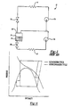
Figure 1 illustrates a schematic diagram of a prior art vapor compression system. -
Figure 2 illustrates a thermodynamic diagram of a transcritical vapor compression system. -
Figure 3 illustrates a schematic diagram of a prior art two stage vapor compression system utilizing a flash tank. -
Figure 4 illustrates a thermodynamic diagram of a two stage economized cycle and a noneconomized cycle of a transcritical vapor compression cycle. -
Figure 5 illustrates a schematic diagram of a flash tank of a two stage vapor compression system in accordance with the invention and utilizing expansion valves to control the high pressure of the system. -
Figure 6 illustrates a schematic diagram of a two stage flash tank of a vapor compression system in accordance with the invention and utilizing additional valves to control the high pressure of the system. -
Figure 1 illustrates a prior artvapor compression system 10. A basicvapor compression system 10 consists of acompressor 12, a heat rejecting heat exchanger (a gas cooler in transcritical cycles) 14, anexpansion device 16, and a heat accepting heat exchanger (an evaporator) 18. - Refrigerant is circulated though the closed
circuit cycle 10. In preferred embodiments of the invention, carbon dioxide is used as the refrigerant. While carbon dioxide is illustrated, other refrigerants may be used. Because carbon dioxide has a low critical point, systems utilizing carbon dioxide as a refrigerant usually require thevapor compression system 10 to run transcritical. - When the
system 10 is run transcritical, it is advantageous to regulate the high pressure component of thevapor compression system 10. By regulating the high pressure of thesystem 10, the capacity and/or efficiency of thesystem 10 can be controlled and optimized. Increasing thegas cooler 14 pressure lowers the enthalpy entering theevaporator 18 and increases capacity, but also requires more energy because thecompressor 16 must work harder. By regulating the high pressure of thesystem 10, the optimal pressure of thesystem 10, which changes as the operating conditions change, can be selected. - In a cycle of a prior art
vapor compression system 10 illustrated inFigure 1 , the refrigerant exits thecompressor 12 at high pressure and enthalpy, shown by point A inFigure 2 . As the refrigerant flows through thegas cooler 14 at high pressure, it loses heat and enthalpy, exiting thegas cooler 14 with low enthalpy and high pressure, indicated as point B. As the refrigerant passes through theexpansion device 16, the pressure of the refrigerant drops, shown by point C. After expansion, the refrigerant passes through theevaporator 18 and exits at a high enthalpy and low pressure, represented by point D. After the refrigerant passes through thecompressor 12, it is again at high pressure and enthalpy, completing the cycle. -
Figure 3 illustrates avapor compression system 10 employing aflash tank 20 in a two stage economized cycle. The refrigerant exiting thegas cooler 14 is passed through afirst expansion device 16a, reducing its pressure. The refrigerant collects in aflash tank 20 aspart liquid 24 andpart vapor 22. The structure of theflash tank 20 is known and forms no part of this invention. Theflash tank 20 is controlled in an inventive way in the invention of this application. Thevapor 22 is drawn at the top of theflash tank 20 and is used to cool refrigerant that exits thefirst compression device 12a. Theliquid refrigerant 24 collects at the bottom of theflash tank 20 and is again expanded by a second expansion device 16b before entering theevaporator 18. After the refrigerant passes through theevaporator 18, it is compressed by thefirst compression device 12a, the exhaust being cooled by the cool refrigerant vapor discharged 22 from theflash tank 20, The refrigerant is then compressed again by asecond compression device 12b before entering thegas cooler 14. By using theflash tank 20, the specific enthalpy of the system can be reduced, which increases the capacity of thesystem 10. However, theflash tank 20 has no effect on the high pressure in thegas cooler 14, which would allow for more control over the high pressure of thesystem 10. - By utilizing multistage compression, the efficiency of the economized
system 10 can be increased where there is a large difference between the high and low pressures in a system. As known, aline 23 communicatesvapor 22 to the suction part of thecompression stage 12b. This provides cooling, and is known as economized operation. A thermodynamic diagram of both an economized cycle and a noneconomized cycle is illustrated inFigure 4 . Economization allows for greater mass flow through thegas cooler 14, and reduces the specific enthalpy of the refrigerant that enters theevaporator 18, causing the cycle to have greater cooling capacity. -
Figure 5 illustrates aflash tank 20 andexpansion valves first expansion valve 26 regulates the flow of charge into theflash tank 20 and asecond expansion valve 28 regulates the flow of charge out of theflash tank 20, - As known, the flow rate of the charge through the
first expansion valve 26 and thesecond expansion valve 28 is a function of the pressure in thesystem 10 and the diameter of an orifice in theexpansion valves expansion valves expansion valves expansion valves expansion valves expansion valves expansion valves flash tank 20, and thegas cooler 14, can be regulated to control the pressure in thegas cooler 14. -
Control 29 monitors the pressure in the cooler 14 and controlsexpansion valves control 29 may be the main control forcycle 10.Control 29 is programmed to evaluate the state ofcycle 10 and determine a desired pressure in cooler 14. Once a desired pressure has been determined, theexpansion valves - If the pressure in the
gas cooler 14 is above the optimal pressure, a large amount of energy is used to compress the refrigerant.Control 29 actuates thesecond expansion valve 28 to close and reduce the volume flow of charge out of theflash tank 20, increasing the amount of charge in theflash tank 20, decreasing both the amount of charge and the pressure in thegas cooler 14. Conversely, if the pressure in thegas cooler 14 pressure is below the optimal pressure, the efficiency of thesystem 10 could be increased.Control 29 closes thefirst expansion valve 26 to decrease the volume flow of charge into theflash tank 20, increasing both the amount of charge and the pressure in thegas cooler 14. - The pressure in the
gas cooler 14 is monitored bycontroller 29. As the pressure in the gas cooler 14 changes, thecontroller 29 adjusts the actuation of theexpansion valves - By selectively controlling the actuation of the
first expansion valve 26 and thesecond expansion valve 28, the amount of charge stored in theflash tank 20 can be varied, which varies the high pressure component in thesystem 10 to achieve optimal capacity and/or efficiency. By regulating the high pressure in thegas cooler 14 before expansion, the enthalpy of the refrigerant at the entry of the evaporator can be modified, controlling the capacity and/or efficiency of thesystem 10. - While the simplest way to visualize the
invention control 29 is to closevalve 26 to decrease volume in theflash tank 20 andclose valve 28 to increase volume,valve 26 can be opened to increase flow andvalve 28 can be opened to decrease volume. - As shown in
Figure 6 , athird valve 30 and afourth valve 32 can also be employed to vary the charge level in theflash tank 20 and optimize efficiency and/or capacity of thesystem 10. Thefourth valve 32 controls the flow of charge from theflash tank 20 to thecompression device 12. By closing thefourth valve 32, the economizer is turned off and thevapor refrigerant 22 exiting theflash tank 20 is blocked from entering thecompressor 12. Closing thefourth valve 32 traps thevapor refrigerant 20 in theflash tank 20. Thethird valve 30 acts as a release and opening thethird valve 30 allows the flow of charge from theflash tank 20 to theevaporator 18. By opening thethird valve 30, the vapor refrigerant 22 from theflash tank 20 is allowed to enter theevaporator 18, creating an escape for thevapor 22. Alternatively, thefourth valve 32 can be opened to turn on the economizer. By controllingvalves system 10. The actuation ofvalves controller 29 which monitors the pressure in thegas cooler 14. - Accordingly, the present invention provides a
flash tank 20 utilizingexpansion valves vapor compression system 10. - The foregoing description is only exemplary of the principles of the invention. Many modifications and variations of the present invention are possible in light of the above teachings. The preferred embodiments of this invention have been disclosed, however, so that one of ordinary skill in the art would recognize that certain modifications would come within the scope of this invention. It is, therefore, to be understood that within the scope of the appended claims, the invention may be practiced otherwise than as specially described. For that reason the following claims should be studied to determine the true scope and content of this invention.
Claims (17)
- A transcritical vapor compression system (10) comprising:a dual compression device having a first compression device (12a) and a second compression device (12b), said dual compression device compressing a refrigerant to a high pressure;a heat rejecting heat exchanger (14) for cooling said refrigerant;a dual expansion device having a first expansion valve (26) and a second expansion valve (28), said dual expansion device reducing said refrigerant to a low pressure;a heat accepting heat exchanger (18) for evaporating said refrigerant; anda flash tank (20) for regulating said high pressure of said system positioned between said first expansion valve (26) and said second expansion valve (28), said first expansion valve (26) regulating flow of said charge into said flash tank (20), and said second expansion valve (28) regulating flow of said charge out of said flash tank (20), said first expansion valve (26) and said second expansion valve (28) being actuated to regulate said high pressure by regulating said amount of charge in said flash tank (20).
- The system as recited in claim 1, wherein said high pressure is regulated by actuating said first expansion valve (26) and said second expansion valve (28) to control said amount of charge in said flash tank (20).
- The system as recited in claim 1 or 2, wherein said charge is stored in said flash tank (20) to decrease said high pressure of said refrigerant and is released from said flash tank (20) to increase said high pressure of said refrigerant.
- The system as recited in any preceding claim, wherein said first and second expansion valves (26, 28) are controlled to decrease said charge in said flash tank (20) and to increase said high pressure of said refrigerant.
- The system as recited in any preceding claim, wherein said first and second expansion valves (26, 28) are controlled to increase said charge in said flash tank (20) and to decrease said high pressure of said refrigerant.
- The system as recited in any preceding claim, wherein said first and second expansion valves (26, 28) are actuated to optimize the capacity and/or efficiency of the system.
- The system as recited in any preceding claim, further comprising a third valve (30) positioned to regulate flow of said charge from said flash tank (20) to the heat accepting heat exchanger (18).
- The system as recited in claim 7, wherein said third valve (30) is actuated to release vapor charge from said flash tank (20) and to allow said vapor to flow to said heat accepting heat exchanger (18).
- The system as recited in claim 7 or 8, wherein said third valve (30) is actuated to optimize the capacity and/or efficiency of the system.
- The system as recited in any preceding claim, further comprising a fourth valve (32) positioned to regulate flow of said charge from said flash tank (20) to the dual compression device.
- The system as recited in claim 10, wherein said fourth valve (32) is actuated to block vapor charge from entering the dual compression device.
- The system as recited in claim 10 or 11, wherein said fourth valve (32) is actuated to optimize the capacity and/or efficiency of the system.
- The system as recited in any preceding claim, comprising a valve positioned to regulate flow of said charge from said flash tank (20), wherein said valve is actuated to release vapor charge from said flash tank (20) and to allow said vapor to flow out of said flash tank (20).
- The system as recited in any preceding claim, wherein said dual compression device comprises an inter compression stage between said first compression device (12a) and said second compression device (12b), and comprising:a first path leading from said flash tank (20) to said inter compression stage; anda valve (32) positioned in said first path for regulating the flow of vapor charge from said flash tank (20) to the inter compression stage of said dual compression device.
- The system as claimed in claim 14, comprising:a second path leading from said first path to said heat accepting heat exchanger (18); anda valve (30) positioned in said second path for regulating the flow of vapor charge from said flash tank (20) to the heat accepting heat exchanger (18).
- The system as recited in any preceding claim wherein said refrigerant is carbon dioxide.
- A method of regulating a high pressure of a refrigerant in a transcritical vapor compression system (10) by regulating an amount of charge in a flash tank (20), the method comprising the steps of:compressing a refrigerant in two stages of compression to said high pressure;cooling said refrigerant;expanding said refrigerant in two stages to a low pressure;evaporating said refrigerant; andcontrolling said high pressure by passing the refi-igerant through a flash tank (20) positioned between the stages of expansion, an amount of charge in said flash tank (20) being controlled by a first expansion valve (26) regulating flow of said charge into said flash tank (20) and a second expansion valve (28) regulating flow of said charge out of said flash tank (20).
Applications Claiming Priority (2)
| Application Number | Priority Date | Filing Date | Title |
|---|---|---|---|
| US09/713,090 US6385980B1 (en) | 2000-11-15 | 2000-11-15 | High pressure regulation in economized vapor compression cycles |
| EP01309594A EP1207359B1 (en) | 2000-11-15 | 2001-11-14 | High pressure regulation in a transcritical vapor compression cycle |
Related Parent Applications (2)
| Application Number | Title | Priority Date | Filing Date |
|---|---|---|---|
| EP01309594.8 Division | 2001-11-14 | ||
| EP01309594A Division EP1207359B1 (en) | 2000-11-15 | 2001-11-14 | High pressure regulation in a transcritical vapor compression cycle |
Publications (3)
| Publication Number | Publication Date |
|---|---|
| EP1914492A2 true EP1914492A2 (en) | 2008-04-23 |
| EP1914492A3 EP1914492A3 (en) | 2008-10-22 |
| EP1914492B1 EP1914492B1 (en) | 2012-06-27 |
Family
ID=24864695
Family Applications (2)
| Application Number | Title | Priority Date | Filing Date |
|---|---|---|---|
| EP07024776A Expired - Lifetime EP1914492B1 (en) | 2000-11-15 | 2001-11-14 | High pressure regulation in a transcritical vapor compression cycle |
| EP01309594A Expired - Lifetime EP1207359B1 (en) | 2000-11-15 | 2001-11-14 | High pressure regulation in a transcritical vapor compression cycle |
Family Applications After (1)
| Application Number | Title | Priority Date | Filing Date |
|---|---|---|---|
| EP01309594A Expired - Lifetime EP1207359B1 (en) | 2000-11-15 | 2001-11-14 | High pressure regulation in a transcritical vapor compression cycle |
Country Status (9)
| Country | Link |
|---|---|
| US (1) | US6385980B1 (en) |
| EP (2) | EP1914492B1 (en) |
| JP (1) | JP4053283B2 (en) |
| CN (1) | CN1190636C (en) |
| AU (1) | AU766121B2 (en) |
| DE (1) | DE60132287T2 (en) |
| DK (1) | DK1207359T3 (en) |
| ES (1) | ES2296714T3 (en) |
| TW (1) | TW589441B (en) |
Cited By (1)
| Publication number | Priority date | Publication date | Assignee | Title |
|---|---|---|---|---|
| US9492823B2 (en) | 2009-10-21 | 2016-11-15 | Biocartis Nv | Manifold for a fluidic cartridge |
Families Citing this family (90)
| Publication number | Priority date | Publication date | Assignee | Title |
|---|---|---|---|---|
| US7065979B2 (en) * | 2002-10-30 | 2006-06-27 | Delaware Capital Formation, Inc. | Refrigeration system |
| JP3940840B2 (en) * | 2002-11-22 | 2007-07-04 | ダイキン工業株式会社 | Air conditioner |
| JP2004308972A (en) * | 2003-04-03 | 2004-11-04 | Mayekawa Mfg Co Ltd | Co2 refrigerating machine |
| US7424807B2 (en) * | 2003-06-11 | 2008-09-16 | Carrier Corporation | Supercritical pressure regulation of economized refrigeration system by use of an interstage accumulator |
| ES2235681T3 (en) * | 2003-07-18 | 2010-08-31 | Star Refrigeration Ltd. | IMPROVED TRANSCRITICAL COOLING CYCLE. |
| US6923011B2 (en) * | 2003-09-02 | 2005-08-02 | Tecumseh Products Company | Multi-stage vapor compression system with intermediate pressure vessel |
| US6959557B2 (en) * | 2003-09-02 | 2005-11-01 | Tecumseh Products Company | Apparatus for the storage and controlled delivery of fluids |
| US6813895B2 (en) * | 2003-09-05 | 2004-11-09 | Carrier Corporation | Supercritical pressure regulation of vapor compression system by regulation of adaptive control |
| US7299649B2 (en) * | 2003-12-09 | 2007-11-27 | Emerson Climate Technologies, Inc. | Vapor injection system |
| US7096679B2 (en) * | 2003-12-23 | 2006-08-29 | Tecumseh Products Company | Transcritical vapor compression system and method of operating including refrigerant storage tank and non-variable expansion device |
| US7131294B2 (en) | 2004-01-13 | 2006-11-07 | Tecumseh Products Company | Method and apparatus for control of carbon dioxide gas cooler pressure by use of a capillary tube |
| JP2005257236A (en) * | 2004-03-15 | 2005-09-22 | Sanyo Electric Co Ltd | Freezing device |
| JP2005257237A (en) | 2004-03-15 | 2005-09-22 | Sanyo Electric Co Ltd | Refrigeration unit |
| KR100642709B1 (en) * | 2004-03-19 | 2006-11-10 | 산요덴키가부시키가이샤 | Refrigerator |
| US6973797B2 (en) * | 2004-05-10 | 2005-12-13 | York International Corporation | Capacity control for economizer refrigeration systems |
| US20080098760A1 (en) * | 2006-10-30 | 2008-05-01 | Electro Industries, Inc. | Heat pump system and controls |
| US7849700B2 (en) * | 2004-05-12 | 2010-12-14 | Electro Industries, Inc. | Heat pump with forced air heating regulated by withdrawal of heat to a radiant heating system |
| US7716943B2 (en) | 2004-05-12 | 2010-05-18 | Electro Industries, Inc. | Heating/cooling system |
| US7802441B2 (en) * | 2004-05-12 | 2010-09-28 | Electro Industries, Inc. | Heat pump with accumulator at boost compressor output |
| US20080196420A1 (en) * | 2004-08-09 | 2008-08-21 | Andreas Gernemann | Flashgas Removal From a Receiver in a Refrigeration Circuit |
| CN100507402C (en) * | 2004-08-09 | 2009-07-01 | 卡里尔公司 | CO2 refrigeration circuit with sub-cooling of the liquid refrigerant against the receiver flash gas and method for operating the same |
| JP2006053390A (en) | 2004-08-12 | 2006-02-23 | Fuji Photo Film Co Ltd | Production line of photosensitive film |
| JP4049769B2 (en) * | 2004-08-12 | 2008-02-20 | 三洋電機株式会社 | Refrigerant cycle equipment |
| US7600390B2 (en) * | 2004-10-21 | 2009-10-13 | Tecumseh Products Company | Method and apparatus for control of carbon dioxide gas cooler pressure by use of a two-stage compressor |
| KR100671301B1 (en) * | 2004-12-22 | 2007-01-19 | 삼성전자주식회사 | Air conditioner |
| RU2375649C2 (en) * | 2005-02-18 | 2009-12-10 | Кэрриер Корпорейшн | Cooling system with fluid/steam receiver |
| JP5090932B2 (en) * | 2005-03-03 | 2012-12-05 | ゲーエーアー リフリジェレイション ジャーマニー ゲゼルシャフト ミット ベシュレンクテル ハフツング | Cooling device for transcritical operation with economizer |
| US8037710B2 (en) | 2005-08-22 | 2011-10-18 | Emerson Climate Technologies, Inc. | Compressor with vapor injection system |
| US7275385B2 (en) * | 2005-08-22 | 2007-10-02 | Emerson Climate Technologies, Inc. | Compressor with vapor injection system |
| US20070151269A1 (en) * | 2005-12-30 | 2007-07-05 | Johnson Controls Technology Company | System and method for level control in a flash tank |
| US20070251256A1 (en) * | 2006-03-20 | 2007-11-01 | Pham Hung M | Flash tank design and control for heat pumps |
| US7891201B1 (en) | 2006-09-29 | 2011-02-22 | Carrier Corporation | Refrigerant vapor compression system with flash tank receiver |
| EP1921399A3 (en) * | 2006-11-13 | 2010-03-10 | Hussmann Corporation | Two stage transcritical refrigeration system |
| CN101548142B (en) * | 2006-11-30 | 2013-04-24 | 开利公司 | Refrigerant charge storage |
| JP4875484B2 (en) * | 2006-12-28 | 2012-02-15 | 三菱重工業株式会社 | Multistage compressor |
| DE102007003989A1 (en) * | 2007-01-26 | 2008-07-31 | Grasso Gmbh Refrigeration Technology | CO2 refrigeration system with oil-immersed screw compressors in two-stage arrangement |
| JP2010525294A (en) | 2007-04-24 | 2010-07-22 | キャリア コーポレイション | Refrigerant vapor compression system with two-line economizer circuit |
| WO2008130357A1 (en) | 2007-04-24 | 2008-10-30 | Carrier Corporation | Refrigerant vapor compression system and method of transcritical operation |
| CN101688725B (en) * | 2007-04-24 | 2013-03-27 | 开利公司 | Transcritical refrigerant vapor compression system with charge management |
| WO2008140454A1 (en) | 2007-05-14 | 2008-11-20 | Carrier Corporation | Refrigerant vapor compression system with flash tank economizer |
| US20100251750A1 (en) * | 2007-05-17 | 2010-10-07 | Carrier Corporation | Economized refrigerant system with flow control |
| US20100024470A1 (en) * | 2007-05-23 | 2010-02-04 | Alexander Lifson | Refrigerant injection above critical point in a transcritical refrigerant system |
| JP4898556B2 (en) * | 2007-05-23 | 2012-03-14 | 株式会社日立ハイテクノロジーズ | Plasma processing equipment |
| NO327832B1 (en) * | 2007-06-29 | 2009-10-05 | Sinvent As | Steam circuit compression dress system with closed circuit as well as method for operating the system. |
| US20090025405A1 (en) * | 2007-07-27 | 2009-01-29 | Johnson Controls Technology Company | Economized Vapor Compression Circuit |
| WO2009041959A1 (en) * | 2007-09-24 | 2009-04-02 | Carrier Corporation | Refrigerant system with bypass line and dedicated economized flow compression chamber |
| DK2212631T3 (en) * | 2007-10-10 | 2017-03-06 | Carrier Corp | COOLING SYSTEM AND PROCEDURE FOR CONTROL THEREOF |
| DE102007051118B4 (en) | 2007-10-24 | 2021-11-11 | Konvekta Ag | Expansion valve |
| JP2011503504A (en) * | 2007-11-09 | 2011-01-27 | キャリア コーポレイション | Transport refrigeration system and method of operating the same |
| CN101939601B (en) | 2007-11-13 | 2013-05-08 | 开利公司 | Refrigeration system and method for refrigeration |
| KR100922222B1 (en) | 2007-12-24 | 2009-10-20 | 엘지전자 주식회사 | Air conditioning system |
| EP2229562B1 (en) | 2008-01-17 | 2018-09-05 | Carrier Corporation | Carbon dioxide refrigerant vapor compression system |
| DK2229579T3 (en) * | 2008-01-17 | 2018-12-17 | Carrier Corp | Detection of CO2 emissions in a container |
| ITBO20080067A1 (en) * | 2008-01-31 | 2009-08-01 | Carpigiani Group Ali Spa | MACHINE FOR THE PRODUCTION AND DISTRIBUTION OF LIQUID AND SEMILEQUID CONSUMPTION FOOD PRODUCTS. |
| EP2304338A4 (en) * | 2008-05-14 | 2014-09-03 | Carrier Corp | Transport refrigeration system and method of operation |
| US8631666B2 (en) * | 2008-08-07 | 2014-01-21 | Hill Phoenix, Inc. | Modular CO2 refrigeration system |
| CN102165276B (en) * | 2008-09-29 | 2013-03-27 | 开利公司 | Vapor compression system with flash tank economizer and control method thereof |
| JP5539996B2 (en) | 2008-10-01 | 2014-07-02 | キャリア コーポレイション | Liquid and vapor separation in a transcritical refrigerant cycle. |
| CA2738874C (en) * | 2008-10-23 | 2012-07-10 | Serge Dube | Co2 refrigeration system |
| GB2469616B (en) * | 2009-02-11 | 2013-08-28 | Star Refrigeration | A refrigeration system operable under transcritical conditions |
| DK2417406T3 (en) * | 2009-04-09 | 2019-04-23 | Carrier Corp | Coolant vapor compression system with hot gas bypass |
| EP3379178B1 (en) * | 2009-07-31 | 2023-12-13 | Johnson Controls Tyco IP Holdings LLP | Refrigerant control method |
| DK2504641T3 (en) * | 2009-11-25 | 2019-02-25 | Carrier Corp | PROTECTION FROM LOW SUCTION PRESSURE IN COOLING STEAM COMPRESSION SYSTEM |
| EP2339265B1 (en) * | 2009-12-25 | 2018-03-28 | Sanyo Electric Co., Ltd. | Refrigerating apparatus |
| US9068765B2 (en) | 2010-01-20 | 2015-06-30 | Carrier Corporation | Refrigeration storage in a refrigerant vapor compression system |
| US10047989B2 (en) | 2010-03-08 | 2018-08-14 | Carrier Corporation | Capacity and pressure control in a transport refrigeration system |
| US9657977B2 (en) | 2010-11-17 | 2017-05-23 | Hill Phoenix, Inc. | Cascade refrigeration system with modular ammonia chiller units |
| US9664424B2 (en) | 2010-11-17 | 2017-05-30 | Hill Phoenix, Inc. | Cascade refrigeration system with modular ammonia chiller units |
| US9541311B2 (en) | 2010-11-17 | 2017-01-10 | Hill Phoenix, Inc. | Cascade refrigeration system with modular ammonia chiller units |
| CN103380337B (en) | 2011-02-14 | 2016-09-21 | 开利公司 | Liquid and Vapor Phase Separation Equipment |
| PL2729743T3 (en) * | 2011-07-05 | 2020-11-16 | Danfoss A/S | A method for controlling operation of a vapour compression system in a subcritical and a supercritical mode |
| US9682330B1 (en) * | 2011-08-19 | 2017-06-20 | Raymond C. Sherry | Cleaning system components with abrasives |
| CA2899277C (en) * | 2013-01-25 | 2018-07-17 | Emerson Climate Technologies Retail Solutions, Inc. | System and method for control of a transcritical refrigeration system |
| ES2988494T3 (en) | 2013-05-03 | 2024-11-20 | Hill Phoenix Inc | Systems and methods for pressure control in a CO2 refrigeration system |
| CN103256761B (en) * | 2013-05-17 | 2015-02-25 | 山东格瑞德集团有限公司 | Horizontal flash tank for centrifugal unit |
| CN104110914A (en) * | 2014-07-08 | 2014-10-22 | 北京工业大学 | Piston-type high-temperature heat pump device for waste heat recovery |
| US10240837B2 (en) | 2014-07-30 | 2019-03-26 | Mitsubishi Electric Corporation | Outdoor unit and refrigeration cycle apparatus |
| JP6555584B2 (en) * | 2015-09-11 | 2019-08-07 | パナソニックIpマネジメント株式会社 | Refrigeration equipment |
| CN106766441A (en) | 2015-11-25 | 2017-05-31 | 开利公司 | Refrigeration system and its throttling control method |
| US10543737B2 (en) | 2015-12-28 | 2020-01-28 | Thermo King Corporation | Cascade heat transfer system |
| CN105698454B (en) * | 2016-03-11 | 2017-12-08 | 西安交通大学 | A kind of control method of transcritical CO_2 heat pump optimum pressure |
| US11125483B2 (en) | 2016-06-21 | 2021-09-21 | Hill Phoenix, Inc. | Refrigeration system with condenser temperature differential setpoint control |
| CN106969556A (en) * | 2016-12-31 | 2017-07-21 | 广州市粤联水产制冷工程有限公司 | A kind of flash type economizer and cooling cycle system |
| US11796227B2 (en) | 2018-05-24 | 2023-10-24 | Hill Phoenix, Inc. | Refrigeration system with oil control system |
| US11397032B2 (en) | 2018-06-05 | 2022-07-26 | Hill Phoenix, Inc. | CO2 refrigeration system with magnetic refrigeration system cooling |
| US20210372678A1 (en) * | 2018-10-21 | 2021-12-02 | Proff Investment As | Cooling system |
| US10663201B2 (en) | 2018-10-23 | 2020-05-26 | Hill Phoenix, Inc. | CO2 refrigeration system with supercritical subcooling control |
| US11187437B2 (en) * | 2019-01-09 | 2021-11-30 | Heatcraft Refrigeration Products Llc | Cooling system |
| CN110986405B (en) * | 2019-11-26 | 2021-06-22 | 重庆美的通用制冷设备有限公司 | Heat exchange assembly, heat exchange system and air conditioning equipment |
| US12487017B2 (en) | 2023-06-02 | 2025-12-02 | Hill Phoenix, Inc. | CO2 refrigeration system with supercritical subcooling control |
Family Cites Families (17)
| Publication number | Priority date | Publication date | Assignee | Title |
|---|---|---|---|---|
| JPS60261A (en) * | 1983-06-17 | 1985-01-05 | 株式会社日立製作所 | refrigeration cycle |
| US5245836A (en) * | 1989-01-09 | 1993-09-21 | Sinvent As | Method and device for high side pressure regulation in transcritical vapor compression cycle |
| NO890076D0 (en) * | 1989-01-09 | 1989-01-09 | Sinvent As | AIR CONDITIONING. |
| US5347823A (en) * | 1990-04-06 | 1994-09-20 | Alsenz Richard H | Refrigeration system utilizing an enthalpy expansion jet compressor |
| US5056329A (en) * | 1990-06-25 | 1991-10-15 | Battelle Memorial Institute | Heat pump systems |
| US5174123A (en) * | 1991-08-23 | 1992-12-29 | Thermo King Corporation | Methods and apparatus for operating a refrigeration system |
| CN1079528C (en) * | 1993-10-28 | 2002-02-20 | 株式会社日立制作所 | Refrigeration cycle and its control method |
| US5431026A (en) * | 1994-03-03 | 1995-07-11 | General Electric Company | Refrigerant flow rate control based on liquid level in dual evaporator two-stage refrigeration cycles |
| CN1135341C (en) * | 1994-05-30 | 2004-01-21 | 三菱电机株式会社 | Refrigeration cycle system |
| DE19522884A1 (en) * | 1995-06-23 | 1997-01-02 | Inst Luft Kaeltetech Gem Gmbh | Compression refrigeration circuit operating system |
| JP3331102B2 (en) * | 1995-08-16 | 2002-10-07 | 株式会社日立製作所 | Refrigeration cycle capacity control device |
| JPH09196478A (en) * | 1996-01-23 | 1997-07-31 | Nippon Soken Inc | Refrigerating cycle |
| US5692389A (en) * | 1996-06-28 | 1997-12-02 | Carrier Corporation | Flash tank economizer |
| JPH10174157A (en) | 1996-12-05 | 1998-06-26 | Oi Denki Kk | Delay correction system for radio calling system |
| JPH1163686A (en) | 1997-08-12 | 1999-03-05 | Zexel Corp | Refrigeration cycle |
| JPH11142007A (en) * | 1997-11-06 | 1999-05-28 | Nippon Soken Inc | Refrigeration cycle |
| US6073454A (en) * | 1998-07-10 | 2000-06-13 | Spauschus Associates, Inc. | Reduced pressure carbon dioxide-based refrigeration system |
-
2000
- 2000-11-15 US US09/713,090 patent/US6385980B1/en not_active Expired - Lifetime
-
2001
- 2001-10-25 TW TW090126390A patent/TW589441B/en not_active IP Right Cessation
- 2001-11-13 AU AU89402/01A patent/AU766121B2/en not_active Ceased
- 2001-11-14 DE DE60132287T patent/DE60132287T2/en not_active Expired - Lifetime
- 2001-11-14 EP EP07024776A patent/EP1914492B1/en not_active Expired - Lifetime
- 2001-11-14 ES ES01309594T patent/ES2296714T3/en not_active Expired - Lifetime
- 2001-11-14 EP EP01309594A patent/EP1207359B1/en not_active Expired - Lifetime
- 2001-11-14 DK DK01309594T patent/DK1207359T3/en active
- 2001-11-15 CN CNB011394048A patent/CN1190636C/en not_active Expired - Lifetime
- 2001-11-15 JP JP2001349647A patent/JP4053283B2/en not_active Expired - Lifetime
Non-Patent Citations (1)
| Title |
|---|
| None |
Cited By (1)
| Publication number | Priority date | Publication date | Assignee | Title |
|---|---|---|---|---|
| US9492823B2 (en) | 2009-10-21 | 2016-11-15 | Biocartis Nv | Manifold for a fluidic cartridge |
Also Published As
| Publication number | Publication date |
|---|---|
| CN1190636C (en) | 2005-02-23 |
| TW589441B (en) | 2004-06-01 |
| AU8940201A (en) | 2002-05-16 |
| CN1356519A (en) | 2002-07-03 |
| US6385980B1 (en) | 2002-05-14 |
| AU766121B2 (en) | 2003-10-09 |
| DE60132287T2 (en) | 2009-01-02 |
| DK1207359T3 (en) | 2008-05-26 |
| EP1207359B1 (en) | 2008-01-09 |
| JP4053283B2 (en) | 2008-02-27 |
| EP1914492B1 (en) | 2012-06-27 |
| EP1207359A3 (en) | 2002-08-28 |
| EP1207359A2 (en) | 2002-05-22 |
| JP2002195673A (en) | 2002-07-10 |
| DE60132287D1 (en) | 2008-02-21 |
| EP1914492A3 (en) | 2008-10-22 |
| ES2296714T3 (en) | 2008-05-01 |
Similar Documents
| Publication | Publication Date | Title |
|---|---|---|
| EP1207359B1 (en) | High pressure regulation in a transcritical vapor compression cycle | |
| US6418735B1 (en) | High pressure regulation in transcritical vapor compression cycles | |
| EP1649223B1 (en) | Supercritical pressure regulation of vapor compression system | |
| EP1631773B1 (en) | Supercritical pressure regulation of economized refrigeration system | |
| EP1207360B1 (en) | Suction line heat exchanger with a storage tank for a transcritical vapor compression cycle | |
| EP1672298A2 (en) | Air conditioner | |
| JP2009243847A (en) | Multiple air conditioner | |
| JP2005098635A (en) | Refrigeration cycle | |
| JP4601392B2 (en) | Refrigeration equipment | |
| JP2017116136A (en) | Air conditioner | |
| KR100591311B1 (en) | Refrigeration cycle device and its control method | |
| JPH0642829A (en) | Refrigerator for low temperature | |
| JP2006125739A (en) | Freezer | |
| JPH049553A (en) | Cryogenic freezer and its operating method | |
| KR20050047852A (en) | Compressor structure for providing oil in air conditioner |
Legal Events
| Date | Code | Title | Description |
|---|---|---|---|
| PUAI | Public reference made under article 153(3) epc to a published international application that has entered the european phase |
Free format text: ORIGINAL CODE: 0009012 |
|
| AC | Divisional application: reference to earlier application |
Ref document number: 1207359 Country of ref document: EP Kind code of ref document: P |
|
| AK | Designated contracting states |
Kind code of ref document: A2 Designated state(s): DE DK ES IE IT NL |
|
| PUAL | Search report despatched |
Free format text: ORIGINAL CODE: 0009013 |
|
| AK | Designated contracting states |
Kind code of ref document: A3 Designated state(s): DE DK ES IE IT NL |
|
| 17P | Request for examination filed |
Effective date: 20090422 |
|
| 17Q | First examination report despatched |
Effective date: 20090527 |
|
| AKX | Designation fees paid |
Designated state(s): DE DK ES IE IT NL |
|
| REG | Reference to a national code |
Ref country code: DE Ref legal event code: R079 Ref document number: 60146782 Country of ref document: DE Free format text: PREVIOUS MAIN CLASS: F25B0009000000 Ipc: F25B0001100000 |
|
| RIC1 | Information provided on ipc code assigned before grant |
Ipc: F25B 1/10 20060101AFI20111103BHEP Ipc: F25B 9/00 20060101ALI20111103BHEP Ipc: F25B 5/04 20060101ALI20111103BHEP |
|
| GRAP | Despatch of communication of intention to grant a patent |
Free format text: ORIGINAL CODE: EPIDOSNIGR1 |
|
| GRAS | Grant fee paid |
Free format text: ORIGINAL CODE: EPIDOSNIGR3 |
|
| GRAA | (expected) grant |
Free format text: ORIGINAL CODE: 0009210 |
|
| AC | Divisional application: reference to earlier application |
Ref document number: 1207359 Country of ref document: EP Kind code of ref document: P |
|
| AK | Designated contracting states |
Kind code of ref document: B1 Designated state(s): DE DK ES IE IT NL |
|
| REG | Reference to a national code |
Ref country code: IE Ref legal event code: FG4D |
|
| REG | Reference to a national code |
Ref country code: DE Ref legal event code: R096 Ref document number: 60146782 Country of ref document: DE Effective date: 20120823 |
|
| REG | Reference to a national code |
Ref country code: NL Ref legal event code: T3 |
|
| PG25 | Lapsed in a contracting state [announced via postgrant information from national office to epo] |
Ref country code: IT Free format text: LAPSE BECAUSE OF FAILURE TO SUBMIT A TRANSLATION OF THE DESCRIPTION OR TO PAY THE FEE WITHIN THE PRESCRIBED TIME-LIMIT Effective date: 20120627 |
|
| PG25 | Lapsed in a contracting state [announced via postgrant information from national office to epo] |
Ref country code: ES Free format text: LAPSE BECAUSE OF FAILURE TO SUBMIT A TRANSLATION OF THE DESCRIPTION OR TO PAY THE FEE WITHIN THE PRESCRIBED TIME-LIMIT Effective date: 20121008 Ref country code: DK Free format text: LAPSE BECAUSE OF FAILURE TO SUBMIT A TRANSLATION OF THE DESCRIPTION OR TO PAY THE FEE WITHIN THE PRESCRIBED TIME-LIMIT Effective date: 20120627 |
|
| PLBE | No opposition filed within time limit |
Free format text: ORIGINAL CODE: 0009261 |
|
| STAA | Information on the status of an ep patent application or granted ep patent |
Free format text: STATUS: NO OPPOSITION FILED WITHIN TIME LIMIT |
|
| 26N | No opposition filed |
Effective date: 20130328 |
|
| REG | Reference to a national code |
Ref country code: DE Ref legal event code: R097 Ref document number: 60146782 Country of ref document: DE Effective date: 20130328 |
|
| REG | Reference to a national code |
Ref country code: IE Ref legal event code: MM4A |
|
| PG25 | Lapsed in a contracting state [announced via postgrant information from national office to epo] |
Ref country code: IE Free format text: LAPSE BECAUSE OF NON-PAYMENT OF DUE FEES Effective date: 20121114 |
|
| PGFP | Annual fee paid to national office [announced via postgrant information from national office to epo] |
Ref country code: NL Payment date: 20131109 Year of fee payment: 13 |
|
| REG | Reference to a national code |
Ref country code: NL Ref legal event code: V1 Effective date: 20150601 |
|
| PG25 | Lapsed in a contracting state [announced via postgrant information from national office to epo] |
Ref country code: NL Free format text: LAPSE BECAUSE OF NON-PAYMENT OF DUE FEES Effective date: 20150601 |
|
| REG | Reference to a national code |
Ref country code: DE Ref legal event code: R082 Ref document number: 60146782 Country of ref document: DE Representative=s name: SCHMITT-NILSON SCHRAUD WAIBEL WOHLFROM PATENTA, DE |
|
| PGFP | Annual fee paid to national office [announced via postgrant information from national office to epo] |
Ref country code: DE Payment date: 20201020 Year of fee payment: 20 |
|
| REG | Reference to a national code |
Ref country code: DE Ref legal event code: R071 Ref document number: 60146782 Country of ref document: DE |