EP1911980A1 - Clip - Google Patents
Clip Download PDFInfo
- Publication number
- EP1911980A1 EP1911980A1 EP06780888A EP06780888A EP1911980A1 EP 1911980 A1 EP1911980 A1 EP 1911980A1 EP 06780888 A EP06780888 A EP 06780888A EP 06780888 A EP06780888 A EP 06780888A EP 1911980 A1 EP1911980 A1 EP 1911980A1
- Authority
- EP
- European Patent Office
- Prior art keywords
- engagement
- attachment
- inner member
- hole
- state
- Prior art date
- Legal status (The legal status is an assumption and is not a legal conclusion. Google has not performed a legal analysis and makes no representation as to the accuracy of the status listed.)
- Withdrawn
Links
- 238000003780 insertion Methods 0.000 claims description 27
- 230000037431 insertion Effects 0.000 claims description 27
- 230000000149 penetrating effect Effects 0.000 claims description 2
- 230000002093 peripheral effect Effects 0.000 description 11
- -1 polypropylene Polymers 0.000 description 3
- 230000003014 reinforcing effect Effects 0.000 description 3
- 239000004743 Polypropylene Substances 0.000 description 2
- 238000000034 method Methods 0.000 description 2
- 229920001155 polypropylene Polymers 0.000 description 2
- 229920005989 resin Polymers 0.000 description 2
- 239000011347 resin Substances 0.000 description 2
- 238000009751 slip forming Methods 0.000 description 2
- 230000003247 decreasing effect Effects 0.000 description 1
- 230000000881 depressing effect Effects 0.000 description 1
- 239000002184 metal Substances 0.000 description 1
- 238000012986 modification Methods 0.000 description 1
- 230000004048 modification Effects 0.000 description 1
- 238000000465 moulding Methods 0.000 description 1
Images


Classifications
-
- F—MECHANICAL ENGINEERING; LIGHTING; HEATING; WEAPONS; BLASTING
- F16—ENGINEERING ELEMENTS AND UNITS; GENERAL MEASURES FOR PRODUCING AND MAINTAINING EFFECTIVE FUNCTIONING OF MACHINES OR INSTALLATIONS; THERMAL INSULATION IN GENERAL
- F16B—DEVICES FOR FASTENING OR SECURING CONSTRUCTIONAL ELEMENTS OR MACHINE PARTS TOGETHER, e.g. NAILS, BOLTS, CIRCLIPS, CLAMPS, CLIPS OR WEDGES; JOINTS OR JOINTING
- F16B2/00—Friction-grip releasable fastenings
- F16B2/20—Clips, i.e. with gripping action effected solely by the inherent resistance to deformation of the material of the fastening
-
- F—MECHANICAL ENGINEERING; LIGHTING; HEATING; WEAPONS; BLASTING
- F16—ENGINEERING ELEMENTS AND UNITS; GENERAL MEASURES FOR PRODUCING AND MAINTAINING EFFECTIVE FUNCTIONING OF MACHINES OR INSTALLATIONS; THERMAL INSULATION IN GENERAL
- F16B—DEVICES FOR FASTENING OR SECURING CONSTRUCTIONAL ELEMENTS OR MACHINE PARTS TOGETHER, e.g. NAILS, BOLTS, CIRCLIPS, CLAMPS, CLIPS OR WEDGES; JOINTS OR JOINTING
- F16B19/00—Bolts without screw-thread; Pins, including deformable elements; Rivets
- F16B19/04—Rivets; Spigots or the like fastened by riveting
- F16B19/08—Hollow rivets; Multi-part rivets
- F16B19/10—Hollow rivets; Multi-part rivets fastened by expanding mechanically
- F16B19/1027—Multi-part rivets
- F16B19/1036—Blind rivets
- F16B19/1081—Blind rivets fastened by a drive-pin
-
- B—PERFORMING OPERATIONS; TRANSPORTING
- B60—VEHICLES IN GENERAL
- B60R—VEHICLES, VEHICLE FITTINGS, OR VEHICLE PARTS, NOT OTHERWISE PROVIDED FOR
- B60R13/00—Elements for body-finishing, identifying, or decorating; Arrangements or adaptations for advertising purposes
- B60R13/02—Internal Trim mouldings ; Internal Ledges; Wall liners for passenger compartments; Roof liners
- B60R13/0206—Arrangements of fasteners and clips specially adapted for attaching inner vehicle liners or mouldings
-
- F—MECHANICAL ENGINEERING; LIGHTING; HEATING; WEAPONS; BLASTING
- F16—ENGINEERING ELEMENTS AND UNITS; GENERAL MEASURES FOR PRODUCING AND MAINTAINING EFFECTIVE FUNCTIONING OF MACHINES OR INSTALLATIONS; THERMAL INSULATION IN GENERAL
- F16B—DEVICES FOR FASTENING OR SECURING CONSTRUCTIONAL ELEMENTS OR MACHINE PARTS TOGETHER, e.g. NAILS, BOLTS, CIRCLIPS, CLAMPS, CLIPS OR WEDGES; JOINTS OR JOINTING
- F16B19/00—Bolts without screw-thread; Pins, including deformable elements; Rivets
- F16B19/04—Rivets; Spigots or the like fastened by riveting
- F16B19/08—Hollow rivets; Multi-part rivets
- F16B19/10—Hollow rivets; Multi-part rivets fastened by expanding mechanically
- F16B19/1027—Multi-part rivets
- F16B19/1036—Blind rivets
- F16B19/109—Temporary rivets, e.g. with a spring-loaded pin
-
- F—MECHANICAL ENGINEERING; LIGHTING; HEATING; WEAPONS; BLASTING
- F16—ENGINEERING ELEMENTS AND UNITS; GENERAL MEASURES FOR PRODUCING AND MAINTAINING EFFECTIVE FUNCTIONING OF MACHINES OR INSTALLATIONS; THERMAL INSULATION IN GENERAL
- F16B—DEVICES FOR FASTENING OR SECURING CONSTRUCTIONAL ELEMENTS OR MACHINE PARTS TOGETHER, e.g. NAILS, BOLTS, CIRCLIPS, CLAMPS, CLIPS OR WEDGES; JOINTS OR JOINTING
- F16B2/00—Friction-grip releasable fastenings
-
- F—MECHANICAL ENGINEERING; LIGHTING; HEATING; WEAPONS; BLASTING
- F16—ENGINEERING ELEMENTS AND UNITS; GENERAL MEASURES FOR PRODUCING AND MAINTAINING EFFECTIVE FUNCTIONING OF MACHINES OR INSTALLATIONS; THERMAL INSULATION IN GENERAL
- F16B—DEVICES FOR FASTENING OR SECURING CONSTRUCTIONAL ELEMENTS OR MACHINE PARTS TOGETHER, e.g. NAILS, BOLTS, CIRCLIPS, CLAMPS, CLIPS OR WEDGES; JOINTS OR JOINTING
- F16B5/00—Joining sheets or plates, e.g. panels, to one another or to strips or bars parallel to them
- F16B5/06—Joining sheets or plates, e.g. panels, to one another or to strips or bars parallel to them by means of clamps or clips
- F16B5/0607—Joining sheets or plates, e.g. panels, to one another or to strips or bars parallel to them by means of clamps or clips joining sheets or plates to each other
- F16B5/0621—Joining sheets or plates, e.g. panels, to one another or to strips or bars parallel to them by means of clamps or clips joining sheets or plates to each other in parallel relationship
- F16B5/065—Joining sheets or plates, e.g. panels, to one another or to strips or bars parallel to them by means of clamps or clips joining sheets or plates to each other in parallel relationship the plates being one on top of the other and distanced from each other, e.g. by using protrusions to keep contact and distance
-
- F—MECHANICAL ENGINEERING; LIGHTING; HEATING; WEAPONS; BLASTING
- F16—ENGINEERING ELEMENTS AND UNITS; GENERAL MEASURES FOR PRODUCING AND MAINTAINING EFFECTIVE FUNCTIONING OF MACHINES OR INSTALLATIONS; THERMAL INSULATION IN GENERAL
- F16B—DEVICES FOR FASTENING OR SECURING CONSTRUCTIONAL ELEMENTS OR MACHINE PARTS TOGETHER, e.g. NAILS, BOLTS, CIRCLIPS, CLAMPS, CLIPS OR WEDGES; JOINTS OR JOINTING
- F16B5/00—Joining sheets or plates, e.g. panels, to one another or to strips or bars parallel to them
- F16B5/06—Joining sheets or plates, e.g. panels, to one another or to strips or bars parallel to them by means of clamps or clips
- F16B5/0607—Joining sheets or plates, e.g. panels, to one another or to strips or bars parallel to them by means of clamps or clips joining sheets or plates to each other
- F16B5/0621—Joining sheets or plates, e.g. panels, to one another or to strips or bars parallel to them by means of clamps or clips joining sheets or plates to each other in parallel relationship
- F16B5/0657—Joining sheets or plates, e.g. panels, to one another or to strips or bars parallel to them by means of clamps or clips joining sheets or plates to each other in parallel relationship at least one of the plates providing a raised structure, e.g. of the doghouse type, for connection with the clamps or clips of the other plate
-
- B—PERFORMING OPERATIONS; TRANSPORTING
- B60—VEHICLES IN GENERAL
- B60R—VEHICLES, VEHICLE FITTINGS, OR VEHICLE PARTS, NOT OTHERWISE PROVIDED FOR
- B60R13/00—Elements for body-finishing, identifying, or decorating; Arrangements or adaptations for advertising purposes
- B60R13/02—Internal Trim mouldings ; Internal Ledges; Wall liners for passenger compartments; Roof liners
- B60R13/0256—Dashboard liners
-
- B—PERFORMING OPERATIONS; TRANSPORTING
- B60—VEHICLES IN GENERAL
- B60R—VEHICLES, VEHICLE FITTINGS, OR VEHICLE PARTS, NOT OTHERWISE PROVIDED FOR
- B60R13/00—Elements for body-finishing, identifying, or decorating; Arrangements or adaptations for advertising purposes
- B60R13/02—Internal Trim mouldings ; Internal Ledges; Wall liners for passenger compartments; Roof liners
- B60R13/0262—Mid-console liners
Definitions
- the present invention relates to a clip for use in attaching an attachment member such as a console box and an instrument panel to an attachment receiving member such as an automobile body.
- the present invention relates to a clip that enables attachment of the attachment member to the attachment receiving member in an extremely easy one-touch operation while the inner member and the outer member, which form the clip, are always handled integrally with each other in a provisionally locked state.
- a console device to be attached on a floor of a vehicle body in Japanese Unexamined Patent Publication No. 11-70838 .
- a fitting hole formed on a flange of the console box and a through hole formed on a seat portion are aligned to two fitting holes formed on the floor of the vehicle body, and in this state, a clip comprising an outer member and an inner member is inserted through the holes.
- Patent Document 1 Japanese Unexamined Patent Publication No. 11-70838 , paragraphs page 4 in the specification and Fig. 2
- the diameter of the outer member is decreased to enable the clip to be detached from the respective fitting holes of the floor and the flange, the fitting hole of the floor, and the through hole of the seating portion.
- the diameter of the outer member is enlarged to restrict the clip by the respective fitting holes and through hole, so as to fasten the console box to the floor of the vehicle body.
- the present invention has been made to solve the problems described above, and an objective thereof is to provide a clip which enables attachment of the attachment member to the attachment receiving member in an extremely easy one-touch operation in a state where the inner member is always handled integrally with the outer member in a provisionally locked state.
- a clip as set forth in claim 1 comprises an inner member provided on an attachment member and having a base body and an operation wall extended from an upper wall of the base body, and an outer member having an insertion portion where the operation wall of the inner member is inserted and having an engagement piece which elastically deforms as the operation wall of the inner member is inserted into the insertion portion, wherein the outer member is inserted into an attachment hole of an attachment receiving member and the operation wall of the inner member is inserted into the insertion portion of the outer member such that the engagement piece of the outer member is elastically deformed and the attachment member is attached to the attachment receiving member, the clip is characterized in that: the inner member has an engagement groove formed on the operation wall, an engagement hole formed next to the engagement groove and an operation hole penetrating the upper wall of the base body and being communicated with the engagement hole, wherein the outer member has a projection formed next to the engagement piece, wherein the engagement piece is engaged with the engagement groove in a first state where the operation wall of the inner member is inserted into the
- a slanted cam portion is formed at one end of the operation wall of the inner member, and the engagement piece does not receive a cam operation due to the slanted cam portion in the first state.
- a thin plate portion is formed at a distal end of the slanted cam portion, and the engagement piece contacts the thin plate portion in the first state.
- the outer member and the inner member which are provided on the attachment member can be always handled integrally with each other.
- the engagement piece is engaged with the engagement hole.
- the inner member and the outer member which are maintained in the first state are inserted into the attachment hole of the attachment receiving member such that the clip is maintained with respect to the attachment receiving member, the inner member is pressed against the attachment receiving member with the attachment member such that the operation wall is further inserted into the insertion portion of the outer member.
- the engagement piece formed on the outer member penetrates through the upper wall of the base body of the inner member and enters the operation hole which is communicated with the engagement hole and the engagement of the engagement piece and the engagement hole can be released via the tool which is inserted from the operation hole. This enables the attachment member to be detached from the attachment receiving member with an extremely simple operation.
- the engagement piece of the outer member since the engagement piece of the outer member does not receive the cam operation due to the slanted cam portion formed on one end of the operation wall in the first state, the engagement piece is not elastically deformed. Therefore, the elastic force of the engagement piece is surely prevented from reducing while the clip maintains the outer member and the inner member integrally with each other.
- Fig. 1 is an exploded view schematically showing an inner member and an outer member which form the clip according to a first embodiment.
- the clip 1 basically comprised of the inner member 2 and the outer member 3.
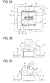
- FIG. 2A is a plane view of the inner member
- Fig. 2B is a cross-sectional view of the inner member taken along A-A line of Fig. 2A
- Fig. 2C is a cross-sectional view of the inner member taken along B-B line of Fig. 2A .
- the inner member 2 is made of various kinds of resins such as polypropylene and integrally molded with an attachment member 4 such as a console box and instrumental panel.
- the inner member 2 is provided on one surface of the attachment member (an upper surface in Fig. 1 ) and has a flat plate portion 5 which is integrally molded with the attachment member 4 with various molding methods.
- the flat plate portion 5 has a base body 6 which is formed in a box.
- An operation wall 7 extends from a substantially center of an upper surface of the base body 6.
- a pair of walls 30 extend from side peripheries of the upper wall 6A of the base body 6 so as to face with each other.
- the operation wall 7 includes a thin plate portion 8, two slanted cam portions 9 and a flat plate wall portion 10 in this order from its distal end.
- the slanted cam portions 9 are formed in a tower-like shape and continuously formed downwardly from the thin plate portion 8.
- the flat plate wall portion 10 is continuously formed from each of the slanted cam portions 9.
- An engagement groove 11 is formed on each slanted cam portion 9.
- an elongated engagement hole 12 is formed at a substantially center of the flat plate wall portion 10 in width direction and next to the engagement groove 11. The engagement groove 11 and the engagement hole 12 are engaged with engagement projections (described later) of the outer member 3 successively according to an insertion degree of the operation wall 7 with respect to the outer member 3.
- Two reinforcing grooves 13 are formed on both sides with respect to the engagement groove 11 and the engagement hole 12.
- the reinforcing grooves 13 are formed on both sides of the operation wall 7.
- Each of the reinforcing grooves 13 is provided for improving strength of the operation wall 7.
- An operation hole 32 is formed on the upper wall 6A of the base body 6 so as to correspond to a lower portion of the engagement hole of the operation wall 7 and the operation hole 32 extends through the upper wall 6A and communicates with the engagement hole 12.
- Figs. 3A to 3C are explanation views showing the outer member in different ways.
- Fig. 3A is a plane view of the outer member
- Fig. 3B is a side view of the outer member
- Fig. 3C is a cross-sectional view of the outer member taken along a C-C line of Fig. 3A .
- the outer member 3 is integrally formed from various resins, for example, polypropylene.
- the outer member 3 includes a bottom portion 15 having a peripheral wall 14.
- An insertion portion 16 is formed at a substantially center of the bottom portion 15 with respect to a width direction.
- the operation wall 7 of the inner member is inserted into the insertion portion 16.
- two pairs of (four) engagement pieces 17 are extended from an upper surface of the bottom portion 15 .
- Each of the engagement pieces 17 is elastically deformable outwardly as the operation wall 7 is inserted into the insertion portion 16.
- a pair of engagement pieces 18 are extended from the upper surface of the bottom portion 15.
- the engagement pieces 18 are elastically deformable.
- a first projection 19 and a second projection 31 are formed on each engagement piece 18.
- Each of the first projections 19 is elastically engaged with the engagement groove 11 and the engagement hole 12 which are formed on the operation wall 7 of the inner member 2.
- Each of the second projections 31 is engaged with the engagement hole 12 while the first projection 19 being engaged with the engagement groove 11.
- FIG. 4A is a cross-sectional view taken along an A-A line of Fig. 2A , which is taken along a width direction of the operation wall
- Fig. 4B is a cross-sectional view taken along an B-B line of Fig. 2A , which is taken along a thickness direction of the operation wall
- Figs. 4A and 4B show a state before the inner member is attached to the outer member
- Fig. 4A is a cross-sectional view taken along an A-A line of Fig. 2A , which is taken along a width direction of the operation wall
- Fig. 4B is a cross-sectional view taken along an B-B line of Fig. 2A , which is taken along a thickness direction of the operation wall
- FIGS. 5A and 5B are explanation views showing a provisionally locked state of the outer member and the inner member in a state where a projection of an engagement piece of the outer member is engaged with an engagement groove of the inner member.
- Fig. 5A is a cross-sectional view taken along the arrow A-A of Fig. 2A and taken along a width direction of the operation wall and
- Fig. 5B is a cross-sectional view taken along the arrow B-B of Fig. 2A and taken along a thickness of the operation wall.
- Figs. 6A and 6B are explanation views showing a state where the provisionally locked inner member and outer member are inserted into an attachment hole of an attachment receiving member.
- Fig. 6A is a cross-sectional view taken along the arrow A-A of Fig.
- Fig. 6B is a cross-sectional view taken along the arrow B-B of Fig. 2A and taken along a thickness direction of the operation wall.
- Figs. 7A and 7B are explanation views showing a state where the projection of the engagement piece of the outer member is engaged with the engagement hole of the inner member such that the outer member and the inner member are locked with each other and the attachment member is attached to the attachment receiving member.
- Fig. 7A is a cross-sectional view taken along the arrow A-A of Fig. 2A and taken along a width direction of the operation wall
- Fig. 7B is a cross-sectional view taken along the arrow B-B of Fig. 2A and taken along a thickness direction of the operation wall.
- each engagement piece 17 is only contacted to both surfaces of the thin plate portion 8 of the operation wall 7 without receiving the cam operation due to each slanted cam member 9 of the operation wall 7 of the inner member 2. Therefore, each engagement piece 17 maintains substantially its original state without being elastically deformed.
- the attachment member 4 is pressed from its surface which is opposite to a surface of the attachment member 4 where the inner member 2 is provided such that the outer member 3 and the inner member 2 are inserted into the attachment hole 22 of the attachment receiving member 21.
- This insertion operation is executed until the upper surface of the peripheral wall portion 14 formed,on the bottom portion 15 of the outer member 3 abuts against the rear surface of the peripheral edge of the attachment hole 22 of the attachment receiving member 21.
- Figs. 6A and 6B In the state shown in Figs.
- the attachment member 4 is pressed toward in a direction in which the outer member 3 and the inner member 2 are further inserted into the attachment hole 22 (in the upper direction in Fig. 6 ). At this time, since the upper surface of the peripheral wall portion 14 of the outer member 3 contacts the peripheral edge of the attachment hole of the attachment receiving member 21, the outer member 3 is not moved when the attachment member 4 being pressed.
- each engagement piece 17 of the outer member 3 gradually receives the cam operation due to each slanted cam portion 9 of the operation wall 7 of the inner member 2 so as to be elastically deformed outwardly.
- the first projection 19 of each engagement projection 18 is engaged with the engagement hole 12 of the operation wall of the inner member 2. This state is shown in Figs. 7A and 7B .
- the inner member 2 and the outer member are locked with each other when the attachment member 4 is attached to the attachment receiving member 21.
- An operation for releasing the locked state and recovering the provisionally locked state and removing the clip 1 from the attachment receiving member 21 will be explained with reference to Figs. 8 to 12 .
- Figs. 8A and 8B are explanation views showing a state where a tool is started to be inserted into an operation hole of the inner member.
- Fig. 8A is a cross-sectional view taken along the arrow A-A of Fig. 2A
- Fig. 8B is a cross-sectional view taken along the arrow B-B of Fig. 2A .
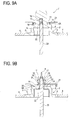
- Figs. 9A and 9B are explanation views showing a state where the tool is further inserted into an engagement hole from the state shown by Figs. 8A and 8B such that the engagement of the engagement piece and the engagement hole is released and the locked state is released.
- Fig. 9A is a cross-sectional view taken along the arrow A-A of Fig. 2A and Fig.
- FIG. 9B is a cross-sectional view taken along the arrow B-B of Fig. 2A .
- Figs. 10A and 10B are explanation views showing a state where the inner member is separated from an attachment receiving member with the attachment member according to the releasing of the locked state.
- Fig. 10A is a cross-sectional view taken along the arrow A-A of Fig. 2A
- Fig. 10B is a cross-sectional view taken along the arrow B-B of Fig. 2A .
- Figs. 11A and 11B are explanation views showing a state where the inner member is further separated from the attachment receiving member from the state shown by Figs. 10A and 10B so as to return to the provisionally locked state.
- Fig. 10A and 10B are explanation views showing a state where the inner member is further separated from the attachment receiving member from the state shown by Figs. 10A and 10B so as to return to the provisionally locked state.
- Fig. 10A and 10B are explanation views showing
- FIG. 11A is a cross-sectional view taken along the arrow A-A of Fig. 2A and Fig. 11B is a cross-sectional view taken along the arrow B-B of Fig. 2A .
- Figs. 12A and 12B are explanation views showing a state where the outer member is removed from the attachment hole of the attachment receiving member with maintaining the provisionally locked state of the inner member and the outer member.
- Fig. 12A is a cross-sectional view taken along the arrow A-A of Fig. 2A and Fig. 12B is a cross-sectional view taken along the arrow B-B of Fig. 2A .
- a tool 33 such as a driver is inserted into the operation hole 32 of the inner member 2 from a side of the inner member 2 opposite to a side where the operation wall 7 is formed.
- a side edge of the tool 33 contacts the second projection 31 and then contacts the first projection 19.
- the engagement piece 18 is elastically deformed so as to be expanded outwardly.
- the engagement piece 18 is thus elastically deformed, the engagement of the first projection 19 of the engagement piece 18 and the engagement hole 12 is released. This releases the locked state.
- This state is shown in Figs. 9A and 9B .
- the inner member 2 is further separated from the attachment receiving member 21 with the tool 33. Accordingly, the first projection 19 of the engagement piece 18 is engaged with the engagement groove 11 of the operation wall 7 and the second projection 31 of the engagement piece 18 is engaged with the engagement hole 12. This enables the inner member 2 and the outer member 3 to be provisionally locked state. This state is shown in Figs. 11A and 11B .
- the outer member 3 is removed from the attachment hole 22 of the attachment receiving member 21 with maintaining the provisionally locked state of the inner member 2 and the outer member 3 shown in Figs. 11A and 11B .
- the first projection and the second projection 31 of each engagement piece 18 are located in the operation hole 32.
- the side edge of the tool 33 contacts the first projection 19 and the engagement piece 18 is elastically deformed and this releases the engagement of the first projection 19 of the engagement piece 18 and the engagement hole 12 to release the locked state.
- the attachment member 4 can be removed from the attachment receiving member 21 with a quite simple operation.
- the present invention provides a clip which enables attachment of the attachment member to the attachment receiving member in an extremely easy one-touch operation in a state where the inner member and the outer member, which form the clip, are always handled integrally with each other in a provisionally locked state.
Abstract
Description
- The present invention relates to a clip for use in attaching an attachment member such as a console box and an instrument panel to an attachment receiving member such as an automobile body. In particular, the present invention relates to a clip that enables attachment of the attachment member to the attachment receiving member in an extremely easy one-touch operation while the inner member and the outer member, which form the clip, are always handled integrally with each other in a provisionally locked state.
- Conventionally, various kinds of clips have been proposed for use in attaching a console box, instrument panel, and the like to various kinds of panels constituting an automobile body.
For example, there is disclosed a console device to be attached on a floor of a vehicle body inJapanese Unexamined Patent Publication No. 11-70838 - [Patent Document 1]
Japanese Unexamined Patent Publication No. 11-70838 paragraphs page 4 in the specification andFig. 2 - In the clip comprising the outer member and inner member described in the
Patent Document 1, when the inner member is withdrawn from the outer member, the diameter of the outer member is decreased to enable the clip to be detached from the respective fitting holes of the floor and the flange, the fitting hole of the floor, and the through hole of the seating portion. When the inner member is inserted into the outer member, the diameter of the outer member is enlarged to restrict the clip by the respective fitting holes and through hole, so as to fasten the console box to the floor of the vehicle body. - When the console box is fastened to the floor of the vehicle body by use of the clip for use in the console device described in the
Patent Document 1, after the inner member is pulled upwardly and the clip with the outer member having a reduced diameter is inserted through the through hole of the seating portion, the inner member is required to be pushed from upward and inserted into the outer member so as to enlarge the diameter of the outer member. - To fasten the console box to the floor of the vehicle body, first of all, it is required to take an operation of pulling out the inner member from the outer member, and in this state, inserting the clip through the fitting holes and through holes, and subsequently, to take an operation of inserting the inner member to the outer member by depressing the inner member into the outer member. These operations are much troublesome, and lead to a problem that much time is required for fastening the console box to the floor of the vehicle body.
- The present invention has been made to solve the problems described above, and an objective thereof is to provide a clip which enables attachment of the attachment member to the attachment receiving member in an extremely easy one-touch operation in a state where the inner member is always handled integrally with the outer member in a provisionally locked state.
- To achieve the above object, a clip as set forth in
claim 1 comprises an inner member provided on an attachment member and having a base body and an operation wall extended from an upper wall of the base body, and an outer member having an insertion portion where the operation wall of the inner member is inserted and having an engagement piece which elastically deforms as the operation wall of the inner member is inserted into the insertion portion, wherein the outer member is inserted into an attachment hole of an attachment receiving member and the operation wall of the inner member is inserted into the insertion portion of the outer member such that the engagement piece of the outer member is elastically deformed and the attachment member is attached to the attachment receiving member, the clip is characterized in that: the inner member has an engagement groove formed on the operation wall, an engagement hole formed next to the engagement groove and an operation hole penetrating the upper wall of the base body and being communicated with the engagement hole, wherein the outer member has a projection formed next to the engagement piece, wherein the engagement piece is engaged with the engagement groove in a first state where the operation wall of the inner member is inserted into the insertion portion of the outer member and the engagement piece is engaged with the engagement hole in a second state where the operation wall is further inserted into the insertion portion, and wherein the projection engaged with the engagement hole in the second state is located in the operation hole and is capable of releasing the engagement with the engagement hole if a tool is inserted from the operation hole. - According to the clip as set forth in
claim 2, in the clip according toclaim 1, a slanted cam portion is formed at one end of the operation wall of the inner member, and the engagement piece does not receive a cam operation due to the slanted cam portion in the first state.
In the clip, as set forth inclaim 3, it is preferable that a thin plate portion is formed at a distal end of the slanted cam portion, and the engagement piece contacts the thin plate portion in the first state. - According to the clip as set forth in
claim 1, since the engagement piece is engaged with the engagement groove in the first state where the operation wall of the inner member is inserted into the insertion portion of the outer member, the outer member and the inner member which are provided on the attachment member can be always handled integrally with each other. - In the second state where the operation wall is further inserted into the insertion portion from the first state where the engagement piece is engaged with the engagement groove, the engagement piece is engaged with the engagement hole. After the inner member and the outer member which are maintained in the first state are inserted into the attachment hole of the attachment receiving member such that the clip is maintained with respect to the attachment receiving member, the inner member is pressed against the attachment receiving member with the attachment member such that the operation wall is further inserted into the insertion portion of the outer member. This simple operation enables the attachment member to be attached to the attachment receiving member via the outer member and the inner member of the clip.
- Further, in the second state where the engagement piece is engaged with the engagement hole of the inner member, the engagement piece formed on the outer member penetrates through the upper wall of the base body of the inner member and enters the operation hole which is communicated with the engagement hole and the engagement of the engagement piece and the engagement hole can be released via the tool which is inserted from the operation hole. This enables the attachment member to be detached from the attachment receiving member with an extremely simple operation.
- According to the clip as set forth in
claim 2, since the engagement piece of the outer member does not receive the cam operation due to the slanted cam portion formed on one end of the operation wall in the first state, the engagement piece is not elastically deformed. Therefore, the elastic force of the engagement piece is surely prevented from reducing while the clip maintains the outer member and the inner member integrally with each other. -
- [
Fig. 1 ] an exploded perspective view schematically showing an inner member and an outer member, which form a clip according to this embodiment - [
Fig. 2A ] a plane view showing the inner member - [
Fig. 2B ] a cross-sectional view showing the inner member taken along the arrow A-A ofFig. 2A - [
Fig. 2C ] a cross-sectional view showing the inner member taken along the arrow B-B ofFig. 2A - [
Fig. 3A ] a plane view showing the outer member - [
Fig. 3B ] a side view showing the outer member - [
Fig. 3C ] a cross-sectional view showing the outer member taken along the arrow C-C ofFig. 3A - [
Fig. 4A ] showing a state before the inner member is attached to the outer member and a cross-sectional view taken along the arrow A-A ofFig. 2A and taken along a width direction of an operation wall - [
Fig. 4B ] showing a state before the inner member is attached to the outer member and a cross-sectional view taken along the arrow B-B ofFig. 2A and taken along a thickness direction of an operation wall - [
Fig. 5A ] an explanation view showing a provisionally locked state of the outer member and the inner member in a state where a projection portion of an engagement piece of the outer member is engaged with an engagement groove of the inner member and a cross-sectional view taken along the arrow A-A ofFig. 2A and taken along a width direction of the operation wall - [
Fig. 5B ] an explanation view showing a provisionally locked state of the outer member and the inner member in a state where a projection portion of an engagement piece of the outer member is engaged with an engagement groove of the inner member and a cross-sectional view taken along the arrow B-B ofFig. 2A and taken along a thickness of the operation wall - [
Fig. 6A ] an explanation view showing a state where the provisionally locked inner member and outer member are inserted into an attachment hole of an attachment receiving member and a cross-sectional view taken along the arrow A-A ofFig. 2A and taken along a width direction of the operation wall - [
Fig. 6B ] an explanation view showing a state where the provisionally locked inner member and outer member are inserted into an attachment hole of an attachment receiving member and a cross-sectional view taken along the arrow B-B ofFig. 2A and taken along a thickness direction of the operation wall - [
Fig. 7A ] an explanation view showing a state where the projection portion of the engagement piece of the outer member is engaged with the engagement hole of the inner member such that the outer member and the inner member are locked with each other and the attachment member is attached to the attachment receiving member, a cross-sectional view taken along the arrow A-A ofFig. 2A and taken along a width direction of the operation wall - [
Fig. 7B ] an explanation view showing a state where the projection portion of the engagement piece of the outer member is engaged with the engagement hole of the inner member such that the outer member and the inner member are locked with each other and the attachment member is attached to the attachment receiving member, a cross-sectional view taken along the arrow B-B ofFig. 2A and taken along a thickness direction of the operation wall - [
Fig. 8A ] an explanation view showing a state where a tool is started to be inserted into an operation hole of the inner member and a cross-sectional view taken along the arrow A-A ofFig. 2A - [
Fig. 8B ] an explanation view showing a state where a tool is started to be inserted into an operation hole of the inner member and a cross-sectional view taken along the arrow B-B ofFig. 2A - [
Fig. 9A ] an explanation view showing a state where the tool is further inserted into an engagement hole from the state shown byFig. 8 such that the engagement of the engagement piece and the engagement hole is released and the locked state is released and a cross-sectional view taken along the arrow A-A ofFig. 2A - [
Fig. 9B ] an explanation view showing a state where the tool is further inserted into an engagement hole from the state shown byFig. 8 such that the engagement of the engagement piece and the engagement hole is released and the locked state is released and a cross-sectional view taken along the arrow B-B ofFig. 2A - [
Fig. 10A ] an explanation view showing a state where the inner member is separated from an attachment receiving member with the attachment member according to the releasing of the locked state and a cross-sectional view taken along the arrow A-A ofFig. 2A - [
Fig. 10B ] an explanation view showing a state where the inner member is separated from an attachment receiving member with the attachment member according to the releasing of the locked state and a cross-sectional view taken along the arrow B-B ofFig. 2A - [
Fig. 11A ] an explanation view showing a state where the inner member is further separated from the attachment receiving member from the state shown byFig. 10 so as to return to the provisionally locked state and a cross-sectional view taken along the arrow A-A ofFig. 2A - [
Fig. 11B ] an explanation view showing a state where the inner member is further separated from the attachment receiving member from the state shown byFig. 10 so as to return to the provisionally locked state and a cross-sectional view taken along the arrow B-B ofFig. 2A - [
Fig. 12A ] an explanation view showing a state where the outer member is removed from the attachment hole of the attachment receiving member with maintaining the provisionally locked state of the inner member and the outer member and a cross-sectional view taken along the arrow A-A ofFig. 2A - [
Fig. 12B ] an explanation view showing a state where the outer member is removed from the attachment hole of the attachment receiving member with maintaining the provisionally locked state of the inner member and the outer member and a cross-sectional view taken along the arrow B-B ofFig. 2A -
- 1
- clip
- 2
- inner member
- 3
- outer member
- 4
- attachment member
- 7
- operation wall
- 8
- thin plate portion
- 9
- slanted cam portion
- 10
- flat plate wall portion
- 11
- engagement groove
- 12
- engagement hole
- 14
- peripheral wall
- 15
- bottom portion
- 16
- insertion portion
- 17
- engagement piece
- 18
- engagement piece
- 19
- first projection
- 21
- attachment receiving member
- 22
- attachment hole
- 32
- operation hole
- 33
- tool
- Hereinafter, a clip according to the present invention will be described in detail with reference to the drawings based on an embodiment which has embodied the present invention. First, an entire structure related to a clip according to this embodiment will be explained with reference to
Fig. 1. Fig. 1 is an exploded view schematically showing an inner member and an outer member which form the clip according to a first embodiment.
InFig. 1 , theclip 1 basically comprised of theinner member 2 and theouter member 3. - A configuration of the
inner member 2 will be explained with reference toFig. 1 andFigs. 2A to 2C. Figs. 2A to 2C are explanation views showing the inner member in different ways.Fig. 2A is a plane view of the inner member,Fig. 2B is a cross-sectional view of the inner member taken along A-A line ofFig. 2A, and Fig. 2C is a cross-sectional view of the inner member taken along B-B line ofFig. 2A . - In
Figs. 1 and2A to 2C , theinner member 2 is made of various kinds of resins such as polypropylene and integrally molded with anattachment member 4 such as a console box and instrumental panel. Theinner member 2 is provided on one surface of the attachment member (an upper surface inFig. 1 ) and has aflat plate portion 5 which is integrally molded with theattachment member 4 with various molding methods. Theflat plate portion 5 has abase body 6 which is formed in a box. Anoperation wall 7 extends from a substantially center of an upper surface of thebase body 6. A pair ofwalls 30 extend from side peripheries of theupper wall 6A of thebase body 6 so as to face with each other. - The
operation wall 7 includes athin plate portion 8, twoslanted cam portions 9 and a flatplate wall portion 10 in this order from its distal end. The slantedcam portions 9 are formed in a tower-like shape and continuously formed downwardly from thethin plate portion 8. The flatplate wall portion 10 is continuously formed from each of the slantedcam portions 9. Anengagement groove 11 is formed on eachslanted cam portion 9. Further, anelongated engagement hole 12 is formed at a substantially center of the flatplate wall portion 10 in width direction and next to theengagement groove 11. Theengagement groove 11 and theengagement hole 12 are engaged with engagement projections (described later) of theouter member 3 successively according to an insertion degree of theoperation wall 7 with respect to theouter member 3.
Two reinforcinggrooves 13 are formed on both sides with respect to theengagement groove 11 and theengagement hole 12. The reinforcinggrooves 13 are formed on both sides of theoperation wall 7. Each of the reinforcinggrooves 13 is provided for improving strength of theoperation wall 7.
Anoperation hole 32 is formed on theupper wall 6A of thebase body 6 so as to correspond to a lower portion of the engagement hole of theoperation wall 7 and theoperation hole 32 extends through theupper wall 6A and communicates with theengagement hole 12. - Next, the
outer member 3 will be explained with reference toFig. 1 andFigs. 3A to 3C. Figs. 3A to 3C are explanation views showing the outer member in different ways.Fig. 3A is a plane view of the outer member,Fig. 3B is a side view of the outer member, andFig. 3C is a cross-sectional view of the outer member taken along a C-C line ofFig. 3A . - The
outer member 3 is integrally formed from various resins, for example, polypropylene. Theouter member 3 includes abottom portion 15 having aperipheral wall 14. Aninsertion portion 16 is formed at a substantially center of thebottom portion 15 with respect to a width direction. As described below, theoperation wall 7 of the inner member is inserted into theinsertion portion 16. Further, on both sides of theinsertion portion 16, two pairs of (four)engagement pieces 17 are extended from an upper surface of thebottom portion 15 . Each of theengagement pieces 17 is elastically deformable outwardly as theoperation wall 7 is inserted into theinsertion portion 16. - On both sides of the
insertion portion 16 and between theengagement pieces 17 along a longitudinal direction of thebottom portion 15, a pair ofengagement pieces 18 are extended from the upper surface of thebottom portion 15. Theengagement pieces 18 are elastically deformable. Afirst projection 19 and a second projection 31 (refer toFig. 3C ) are formed on eachengagement piece 18. Each of thefirst projections 19 is elastically engaged with theengagement groove 11 and theengagement hole 12 which are formed on theoperation wall 7 of theinner member 2. Each of thesecond projections 31 is engaged with theengagement hole 12 while thefirst projection 19 being engaged with theengagement groove 11. - A method for attaching the
attachment member 4 to the attachment receiving member, which is a metal plate (body) of a vehicle body, via theclip 1 which is comprised of theinner member 2 and theouter member 3 will be explained with reference toFigs. 4 to 7 .Figs. 4A and 4B show a state before the inner member is attached to the outer member,Fig. 4A is a cross-sectional view taken along an A-A line ofFig. 2A , which is taken along a width direction of the operation wall,Fig. 4B is a cross-sectional view taken along an B-B line ofFig. 2A , which is taken along a thickness direction of the operation wall,Figs. 5A and 5B are explanation views showing a provisionally locked state of the outer member and the inner member in a state where a projection of an engagement piece of the outer member is engaged with an engagement groove of the inner member.Fig. 5A is a cross-sectional view taken along the arrow A-A ofFig. 2A and taken along a width direction of the operation wall andFig. 5B is a cross-sectional view taken along the arrow B-B ofFig. 2A and taken along a thickness of the operation wall.Figs. 6A and 6B are explanation views showing a state where the provisionally locked inner member and outer member are inserted into an attachment hole of an attachment receiving member.Fig. 6A is a cross-sectional view taken along the arrow A-A ofFig. 2A and taken along a width direction of the operation wall andFig. 6B is a cross-sectional view taken along the arrow B-B ofFig. 2A and taken along a thickness direction of the operation wall.Figs. 7A and 7B are explanation views showing a state where the projection of the engagement piece of the outer member is engaged with the engagement hole of the inner member such that the outer member and the inner member are locked with each other and the attachment member is attached to the attachment receiving member.Fig. 7A is a cross-sectional view taken along the arrow A-A ofFig. 2A and taken along a width direction of the operation wall andFig. 7B is a cross-sectional view taken along the arrow B-B ofFig. 2A and taken along a thickness direction of the operation wall. - In attaching the
attachment member 4 to the attachment receiving member with using theclip 1 according to this embodiment, as shown inFigs. 4A and 4B , theoperation wall 7 of theinner member 2 is located so as to correspond to theinsertion portion 16 of theouter member 3. Then, theouter member 3 is moved toward theinsertion portion 16 such that theoperation wall 7 of the inner member is inserted into theinsertion portion 16. Thereby, thefirst projection 19 formed on eachengagement piece 18 of theouter member 3 is engaged with theengagement groove 11 of theoperation wall 7, and thesecond projection 31 is engaged with theengagement hole 12. At this time, eachengagement piece 17 is contacted to the both sides of thethin plate portion 8 of theoperation wall 7.Figs. 5A and 5B show this state. - As shown in
Figs. 5A and 5B , in a state where thefirst projection 19 formed on eachengagement piece 18 of theouter member 3 is engaged with theengagement groove 11 on theoperation wall 7 and thesecond projection 31 is engaged with theengagement hole 12, eachengagement piece 17 is only contacted to both surfaces of thethin plate portion 8 of theoperation wall 7 without receiving the cam operation due to eachslanted cam member 9 of theoperation wall 7 of theinner member 2. Therefore, eachengagement piece 17 maintains substantially its original state without being elastically deformed. In a state where eachengagement piece 17 of theouter member 3 does not receive the cam operation due to eachslanted cam member 9, thefirst projection 19 of theengagement piece 18 is engaged with theengagement groove 11 and thesecond projection 31 is engaged with theengagement hole 12 such that theinner member 2 and theouter member 3 are provisionally locked with each other. Accordingly, theinner member 2 and theouter member 3 which are attached to theattachment member 4 can be always handled integrally with each other. - Then, in the provisionally locked state in which the
outer member 3 is provisionally locked to theinner member 2 as described above, theattachment member 4 is pressed from its surface which is opposite to a surface of theattachment member 4 where theinner member 2 is provided such that theouter member 3 and theinner member 2 are inserted into theattachment hole 22 of theattachment receiving member 21. This insertion operation is executed until the upper surface of theperipheral wall portion 14 formed,on thebottom portion 15 of theouter member 3 abuts against the rear surface of the peripheral edge of theattachment hole 22 of theattachment receiving member 21. This state is shown inFigs. 6A and 6B . In the state shown inFigs. 6A and 6B , thefirst projection 19 of eachengagement piece 18 of theouter member 3 is engaged with theengagement groove 11 on theoperation wall 7 of theinner member 2, thesecond projection 31 is engaged with theengagement hole 12, and the upper surface of theperipheral wall 14 of thebottom portion 15 of theouter member 3 abuts against the rear surface of the peripheral edge of theattachment hole 22 of theattachment receiving member 21. - From the state shown in
Figs. 6A and 6B , theattachment member 4 is pressed toward in a direction in which theouter member 3 and theinner member 2 are further inserted into the attachment hole 22 (in the upper direction inFig. 6 ). At this time, since the upper surface of theperipheral wall portion 14 of theouter member 3 contacts the peripheral edge of the attachment hole of theattachment receiving member 21, theouter member 3 is not moved when theattachment member 4 being pressed. - The
operation wall 7 of theinner member 2 is inserted into theattachment hole 22 toward theattachment receiving member 21. According to this insertion operation, eachengagement piece 17 of theouter member 3 gradually receives the cam operation due to eachslanted cam portion 9 of theoperation wall 7 of theinner member 2 so as to be elastically deformed outwardly. When eachengagement piece 17 is further elastically deformed outwardly by the cam operation due to the slantedcam portion 9, thefirst projection 19 of eachengagement projection 18 is engaged with theengagement hole 12 of the operation wall of theinner member 2. This state is shown inFigs. 7A and 7B . - In the state shown in
Figs. 7A and 7B , thefirst projection 19 of eachengagement piece 18 of theouter member 3 is engaged with theengagement hole 12 of theoperation wall 7 of the inner member. The upper surface of the peripheral wall of thebottom portion 15 of theouter member 3 abuts against the rear surface of theattachment receiving member 21. Further, the upper surface of eachwall portion 30 formed on the upper surface of thebase body 6 of theinner member 2 abuts against the rear surface of theattachment receiving member 21.
Thereby, theinner member 2 and theouter member 3 are locked and theattachment member 4 is attached to theattachment receiving member 21. - As described above, in a state in which the
first projection 19 of eachengagement piece 18 of theouter member 3 is engaged with theengagement groove 11 and theouter member 3 is inserted into theattachment hole 22 of theattachment receiving member 21 and theperipheral wall 14 of thebottom portion 15 abuts against the peripheral portion of theattachment hole 22, theattachment member 4 is pressed from its surface opposite to one where theinner member 2 is provided toward theattachment receiving member 21. Thereby, thefirst projection 19 of eachengagement piece 18 is engaged with the second engagement hole in the locked state while eachengagement piece 17 receiving the cam operation due to eachslanted cam portion 9 so as to be elastically deformed outwardly. Therefore, in order to attach theattachment member 4 to theattachment receiving member 21, after theinner member 2 and theouter member 3 which are maintained in the provisionally locked state are inserted into theattachment hole 22 of theattachment receiving member 21 such that theclip 1 is supported by theattachment receiving member 21, theinner member 2 is pressed toward theattachment receiving member 21 with theattachment member 4 such that theoperation wall 7 is further inserted into theinsertion portion 16 of theouter member 3. This simple operation enables theattachment member 4 to be attached to theattachment receiving member 21 via theouter member 3 and theinner member 2 of theclip 1. - The
inner member 2 and the outer member are locked with each other when theattachment member 4 is attached to theattachment receiving member 21. An operation for releasing the locked state and recovering the provisionally locked state and removing theclip 1 from theattachment receiving member 21 will be explained with reference toFigs. 8 to 12 . -
Figs. 8A and 8B are explanation views showing a state where a tool is started to be inserted into an operation hole of the inner member.Fig. 8A is a cross-sectional view taken along the arrow A-A ofFig. 2A andFig. 8B is a cross-sectional view taken along the arrow B-B ofFig. 2A .Figs. 9A and 9B are explanation views showing a state where the tool is further inserted into an engagement hole from the state shown byFigs. 8A and 8B such that the engagement of the engagement piece and the engagement hole is released and the locked state is released.Fig. 9A is a cross-sectional view taken along the arrow A-A ofFig. 2A andFig. 9B is a cross-sectional view taken along the arrow B-B ofFig. 2A .Figs. 10A and 10B are explanation views showing a state where the inner member is separated from an attachment receiving member with the attachment member according to the releasing of the locked state.Fig. 10A is a cross-sectional view taken along the arrow A-A ofFig. 2A andFig. 10B is a cross-sectional view taken along the arrow B-B ofFig. 2A .Figs. 11A and 11B are explanation views showing a state where the inner member is further separated from the attachment receiving member from the state shown byFigs. 10A and 10B so as to return to the provisionally locked state.Fig. 11A is a cross-sectional view taken along the arrow A-A ofFig. 2A andFig. 11B is a cross-sectional view taken along the arrow B-B ofFig. 2A .Figs. 12A and 12B are explanation views showing a state where the outer member is removed from the attachment hole of the attachment receiving member with maintaining the provisionally locked state of the inner member and the outer member.Fig. 12A is a cross-sectional view taken along the arrow A-A ofFig. 2A andFig. 12B is a cross-sectional view taken along the arrow B-B ofFig. 2A . - First, when the
attachment member 4 is attached to theattachment receiving member 21, theinner member 2 and theouter member 3 are locked with each other as shown inFigs. 7A and 7B . In the locked state, as shown inFig. 7B , thefirst projection 19 and thesecond projection 31 of eachengagement piece 18 are located in theoperation hole 32. - In the locked state, as shown in
Figs. 8A and 8B , atool 33 such as a driver is inserted into theoperation hole 32 of theinner member 2 from a side of theinner member 2 opposite to a side where theoperation wall 7 is formed. As thetool 33 is inserted into theoperation hole 32, a side edge of thetool 33 contacts thesecond projection 31 and then contacts thefirst projection 19. Accordingly, theengagement piece 18 is elastically deformed so as to be expanded outwardly. When theengagement piece 18 is thus elastically deformed, the engagement of thefirst projection 19 of theengagement piece 18 and theengagement hole 12 is released. This releases the locked state. This state is shown inFigs. 9A and 9B . - In a state where the locked state is released, as the
tool 33 is pulled in a direction opposite to the inserting direction with respect to theoperation hole 32, theinner member 2 is separated from theattachment receiving member 21 with thetool 33. This state is shown inFigs. 10A and 10B . - If the
tool 33 is further pulled from the state shown inFigs. 10A and 10B , theinner member 2 is further separated from theattachment receiving member 21 with thetool 33. Accordingly, thefirst projection 19 of theengagement piece 18 is engaged with theengagement groove 11 of theoperation wall 7 and thesecond projection 31 of theengagement piece 18 is engaged with theengagement hole 12. This enables theinner member 2 and theouter member 3 to be provisionally locked state. This state is shown inFigs. 11A and 11B . - Thereafter, the
outer member 3 is removed from theattachment hole 22 of theattachment receiving member 21 with maintaining the provisionally locked state of theinner member 2 and theouter member 3 shown inFigs. 11A and 11B . - As explained before, according to the
clip 1 of the present embodiment, in the locked state of theinner member 2 and theouter member 3, the first projection and thesecond projection 31 of eachengagement piece 18 are located in theoperation hole 32. When thetool 33 is inserted from theoperation hole 32 formed on theinner member 2 in the locked state, the side edge of thetool 33 contacts thefirst projection 19 and theengagement piece 18 is elastically deformed and this releases the engagement of thefirst projection 19 of theengagement piece 18 and theengagement hole 12 to release the locked state. When thetool 33 is pulled in a direction opposite to the insertion direction with respect to theoperation hole 32, thefirst projection 19 of theengagement piece 18 is engaged with theengagement groove 11 of theoperation wall 7 and the second projection of theengagement piece 18 is engaged with theengagement hole 12 such that theinner member 2 and theouter member 3 are in a provisionally locked state. Therefore, according to the clip of the present embodiment, theattachment member 4 can be removed from theattachment receiving member 21 with a quite simple operation. - The present invention is not limited to the illustrated embodiment. It is a matter of course that various improvements and modifications are possible as far as not departing from the spirit of the present invention.
- The present invention provides a clip which enables attachment of the attachment member to the attachment receiving member in an extremely easy one-touch operation in a state where the inner member and the outer member, which form the clip, are always handled integrally with each other in a provisionally locked state.
Claims (3)
- A clip comprising:an inner member provided on an attachment member and having a base body and an operation wall extended from an upper wall of the base body; andan outer member having an insertion portion where the operation wall of the inner member is inserted and having an engagement piece which elastically deforms as the operation wall of the inner member is inserted into the insertion portion, wherein the outer member is inserted into an attachment hole of an attachment receiving member and the operation wall of the inner member is inserted into the insertion portion of the outer member such that the engagement piece of the outer member is elastically deformed and the attachment member is attached to the attachment receiving member, the clip beingcharacterized in that:the inner member has an engagement groove formed on the operation wall, an engagement hole formed next to the engagement groove and an operation hole penetrating the upper wall of the base body and being communicated with the engagement hole,wherein the outer member has a projection formed next to the engagement piece,
wherein the engagement piece is engaged with the engagement groove in a first state where the operation wall of the inner member is inserted into the insertion portion of the outer member and the engagement piece is engaged with the engagement hole in a second state
where the operation wall is further inserted into the insertion portion, and
wherein the projection engaged with the engagement hole in the second state is located in the operation hole and is capable of releasing the engagement with the engagement hole if a tool is inserted from the operation hole. - The clip according to claim 1, being characterized in that:a slanted cam portion is formed at one end of the operation wall of the inner member, and the engagement piece does not receive a cam operation due to the slanted cam portion in the first state.
- The clip according to claim 2, being characterized in that:a thin plate portion is formed at a distal end of the slanted cam portion, and the engagement piece contacts the thin plate portion in the first state.
Applications Claiming Priority (2)
| Application Number | Priority Date | Filing Date | Title |
|---|---|---|---|
| JP2005220680A JP4677529B2 (en) | 2005-07-29 | 2005-07-29 | clip |
| PCT/JP2006/313613 WO2007013283A1 (en) | 2005-07-29 | 2006-07-07 | Clip |
Publications (2)
| Publication Number | Publication Date |
|---|---|
| EP1911980A1 true EP1911980A1 (en) | 2008-04-16 |
| EP1911980A4 EP1911980A4 (en) | 2008-07-23 |
Family
ID=37683184
Family Applications (1)
| Application Number | Title | Priority Date | Filing Date |
|---|---|---|---|
| EP06780888A Withdrawn EP1911980A4 (en) | 2005-07-29 | 2006-07-07 | Clip |
Country Status (6)
| Country | Link |
|---|---|
| US (1) | US20090110507A1 (en) |
| EP (1) | EP1911980A4 (en) |
| JP (1) | JP4677529B2 (en) |
| KR (1) | KR20080016734A (en) |
| CN (1) | CN100590325C (en) |
| WO (1) | WO2007013283A1 (en) |
Cited By (5)
| Publication number | Priority date | Publication date | Assignee | Title |
|---|---|---|---|---|
| RU2463490C2 (en) * | 2008-03-07 | 2012-10-10 | А.Раймон Э Сие | Device to fix connection element of reinforcement item to support from sheet material |
| EP2698551A1 (en) * | 2012-08-17 | 2014-02-19 | TRW Automotive Electronics & Components GmbH | Retaining clip |
| CN107206946A (en) * | 2015-01-28 | 2017-09-26 | 大众汽车有限公司 | Component for untiedly connecting first component and second component |
| EP3495670A1 (en) * | 2017-12-05 | 2019-06-12 | A. Raymond et Cie | High retention force fastener |
| DE102022134841A1 (en) | 2022-07-25 | 2024-01-25 | GM Global Technology Operations LLC | FASTENING VEHICLE TRIM COMPONENTS |
Families Citing this family (7)
| Publication number | Priority date | Publication date | Assignee | Title |
|---|---|---|---|---|
| CN101688549B (en) * | 2007-07-12 | 2011-11-30 | 百乐仕株式会社 | Latching device |
| JP5307053B2 (en) * | 2010-03-03 | 2013-10-02 | 株式会社ニフコ | Grommet |
| CN101844196A (en) * | 2010-05-26 | 2010-09-29 | 苏州铭峰精密机械有限公司 | Internally riveting clamp |
| US8677573B2 (en) * | 2011-03-24 | 2014-03-25 | Ford Global Technologies, Llc | Two stage serviceable safety clip |
| JP5850891B2 (en) * | 2013-08-27 | 2016-02-03 | 本田技研工業株式会社 | Bonding structure of resin parts |
| JP6486790B2 (en) * | 2015-07-29 | 2019-03-20 | 本田技研工業株式会社 | Clip and connection structure with clip |
| US10328834B2 (en) * | 2016-12-30 | 2019-06-25 | Calsonic Kansei North America, Inc. | Retention clips for vehicle console assembly |
Citations (3)
| Publication number | Priority date | Publication date | Assignee | Title |
|---|---|---|---|---|
| EP0409347A1 (en) * | 1989-07-21 | 1991-01-23 | Ericsson Telecommunicatie B.V. | Coupling system for coupling two parts of a housing |
| EP0908633A1 (en) * | 1997-04-22 | 1999-04-14 | Grupo Antolin-Ingenieria, S.A. | System for fixing accessories to panels and/or self-carrier elements for the internal lining of vehicles |
| EP1186787A1 (en) * | 2000-03-24 | 2002-03-13 | Grupo Antolin-Ingenieria, S.A. | Metal-plastic staple for fixing vehicle roofs and accessories to the body of a vehicle |
Family Cites Families (5)
| Publication number | Priority date | Publication date | Assignee | Title |
|---|---|---|---|---|
| JPH0143532Y2 (en) * | 1986-12-25 | 1989-12-18 | ||
| JPH1170838A (en) | 1997-08-29 | 1999-03-16 | Toyoda Gosei Co Ltd | Mounting and demounting console device for vehicle |
| ES2272015T3 (en) * | 1998-12-31 | 2007-04-16 | Grupo Antolin-Ingenieria S.A. | METALOPLASTIC SYSTEM FOR FIXING PARTS. |
| JP4256541B2 (en) * | 1999-08-06 | 2009-04-22 | 株式会社パイオラックス | Parts mounting structure |
| JP3771399B2 (en) * | 1999-08-08 | 2006-04-26 | 株式会社パイオラックス | Parts mounting structure |
-
2005
- 2005-07-29 JP JP2005220680A patent/JP4677529B2/en not_active Expired - Fee Related
-
2006
- 2006-07-07 EP EP06780888A patent/EP1911980A4/en not_active Withdrawn
- 2006-07-07 US US11/922,423 patent/US20090110507A1/en not_active Abandoned
- 2006-07-07 WO PCT/JP2006/313613 patent/WO2007013283A1/en active Application Filing
- 2006-07-07 KR KR1020087000630A patent/KR20080016734A/en not_active Application Discontinuation
- 2006-07-07 CN CN200680025842A patent/CN100590325C/en not_active Expired - Fee Related
Patent Citations (3)
| Publication number | Priority date | Publication date | Assignee | Title |
|---|---|---|---|---|
| EP0409347A1 (en) * | 1989-07-21 | 1991-01-23 | Ericsson Telecommunicatie B.V. | Coupling system for coupling two parts of a housing |
| EP0908633A1 (en) * | 1997-04-22 | 1999-04-14 | Grupo Antolin-Ingenieria, S.A. | System for fixing accessories to panels and/or self-carrier elements for the internal lining of vehicles |
| EP1186787A1 (en) * | 2000-03-24 | 2002-03-13 | Grupo Antolin-Ingenieria, S.A. | Metal-plastic staple for fixing vehicle roofs and accessories to the body of a vehicle |
Non-Patent Citations (1)
| Title |
|---|
| See also references of WO2007013283A1 * |
Cited By (6)
| Publication number | Priority date | Publication date | Assignee | Title |
|---|---|---|---|---|
| RU2463490C2 (en) * | 2008-03-07 | 2012-10-10 | А.Раймон Э Сие | Device to fix connection element of reinforcement item to support from sheet material |
| EP2698551A1 (en) * | 2012-08-17 | 2014-02-19 | TRW Automotive Electronics & Components GmbH | Retaining clip |
| CN107206946A (en) * | 2015-01-28 | 2017-09-26 | 大众汽车有限公司 | Component for untiedly connecting first component and second component |
| CN107206946B (en) * | 2015-01-28 | 2019-08-30 | 大众汽车有限公司 | For untiedly connecting the component of first component and second component |
| EP3495670A1 (en) * | 2017-12-05 | 2019-06-12 | A. Raymond et Cie | High retention force fastener |
| DE102022134841A1 (en) | 2022-07-25 | 2024-01-25 | GM Global Technology Operations LLC | FASTENING VEHICLE TRIM COMPONENTS |
Also Published As
| Publication number | Publication date |
|---|---|
| WO2007013283A1 (en) | 2007-02-01 |
| CN100590325C (en) | 2010-02-17 |
| JP4677529B2 (en) | 2011-04-27 |
| EP1911980A4 (en) | 2008-07-23 |
| CN101223367A (en) | 2008-07-16 |
| JP2007032795A (en) | 2007-02-08 |
| US20090110507A1 (en) | 2009-04-30 |
| KR20080016734A (en) | 2008-02-21 |
Similar Documents
| Publication | Publication Date | Title |
|---|---|---|
| EP1911980A1 (en) | Clip | |
| US8245367B2 (en) | Fastener | |
| EP1630426B1 (en) | Double clip fastener device with retaining plate | |
| EP1903222A1 (en) | Clip | |
| US20090199371A1 (en) | Clip | |
| EP2518338A1 (en) | Clip | |
| JP2005308221A (en) | Multi-stage assembly auxiliary fastener | |
| JP2008024089A (en) | Interior trim member for vehicle and its removing method | |
| JP2008020006A (en) | Fixing tool with high fixing strength | |
| US20040163218A1 (en) | Spacer for attaching a dash silencer | |
| JP2007315517A (en) | Two piece clip | |
| EP2406504A1 (en) | Fastening device | |
| JP4722458B2 (en) | Metal clip for fixing vehicle accessory and vehicle accessory mounting structure using the same | |
| JP2006046537A (en) | Fastener | |
| JP2007315467A (en) | Component attaching device | |
| EP2199628A1 (en) | Fastener | |
| JP3269017B2 (en) | Anchor clip | |
| JP4320493B2 (en) | clip | |
| JP2011036030A (en) | Clip and wire harness with clip | |
| JP4577468B2 (en) | clip | |
| EP1476057A1 (en) | Clip for fastening a component, such as a footrest, to a workpiece | |
| US20050012010A1 (en) | Clip for fastening a component, such as a footrest, to a workpiece | |
| JP2008057751A (en) | Clip | |
| JP4898853B2 (en) | Cushion material fixing structure for interior parts | |
| JP2005343403A (en) | Hook for floor mat |
Legal Events
| Date | Code | Title | Description |
|---|---|---|---|
| PUAI | Public reference made under article 153(3) epc to a published international application that has entered the european phase |
Free format text: ORIGINAL CODE: 0009012 |
|
| 17P | Request for examination filed |
Effective date: 20080115 |
|
| AK | Designated contracting states |
Kind code of ref document: A1 Designated state(s): DE ES FR GB IT |
|
| A4 | Supplementary search report drawn up and despatched |
Effective date: 20080623 |
|
| RIC1 | Information provided on ipc code assigned before grant |
Ipc: F16B 19/10 20060101AFI20070328BHEP Ipc: B60R 13/02 20060101ALI20080617BHEP Ipc: F16B 21/07 20060101ALI20080617BHEP Ipc: F16B 5/06 20060101ALI20080617BHEP |
|
| DAX | Request for extension of the european patent (deleted) | ||
| RBV | Designated contracting states (corrected) |
Designated state(s): DE ES FR GB IT |
|
| 17Q | First examination report despatched |
Effective date: 20081001 |
|
| GRAP | Despatch of communication of intention to grant a patent |
Free format text: ORIGINAL CODE: EPIDOSNIGR1 |
|
| STAA | Information on the status of an ep patent application or granted ep patent |
Free format text: STATUS: THE APPLICATION IS DEEMED TO BE WITHDRAWN |
|
| 18D | Application deemed to be withdrawn |
Effective date: 20100105 |