EP1911721A1 - Vorrichtung zur erzeugung von wasserstoff - Google Patents
Vorrichtung zur erzeugung von wasserstoff Download PDFInfo
- Publication number
- EP1911721A1 EP1911721A1 EP06780853A EP06780853A EP1911721A1 EP 1911721 A1 EP1911721 A1 EP 1911721A1 EP 06780853 A EP06780853 A EP 06780853A EP 06780853 A EP06780853 A EP 06780853A EP 1911721 A1 EP1911721 A1 EP 1911721A1
- Authority
- EP
- European Patent Office
- Prior art keywords
- hydrogen
- electrode
- fuel
- hydrogen generating
- generating device
- Prior art date
- Legal status (The legal status is an assumption and is not a legal conclusion. Google has not performed a legal analysis and makes no representation as to the accuracy of the status listed.)
- Ceased
Links
Images


Classifications
-
- H—ELECTRICITY
- H01—ELECTRIC ELEMENTS
- H01M—PROCESSES OR MEANS, e.g. BATTERIES, FOR THE DIRECT CONVERSION OF CHEMICAL ENERGY INTO ELECTRICAL ENERGY
- H01M8/00—Fuel cells; Manufacture thereof
- H01M8/06—Combination of fuel cells with means for production of reactants or for treatment of residues
- H01M8/0606—Combination of fuel cells with means for production of reactants or for treatment of residues with means for production of gaseous reactants
- H01M8/0656—Combination of fuel cells with means for production of reactants or for treatment of residues with means for production of gaseous reactants by electrochemical means
-
- C—CHEMISTRY; METALLURGY
- C01—INORGANIC CHEMISTRY
- C01B—NON-METALLIC ELEMENTS; COMPOUNDS THEREOF; METALLOIDS OR COMPOUNDS THEREOF NOT COVERED BY SUBCLASS C01C
- C01B3/00—Hydrogen; Gaseous mixtures containing hydrogen; Separation of hydrogen from mixtures containing it; Purification of hydrogen
- C01B3/02—Production of hydrogen or of gaseous mixtures containing a substantial proportion of hydrogen
- C01B3/32—Production of hydrogen or of gaseous mixtures containing a substantial proportion of hydrogen by reaction of gaseous or liquid organic compounds with gasifying agents, e.g. water, carbon dioxide, air
- C01B3/323—Catalytic reaction of gaseous or liquid organic compounds other than hydrocarbons with gasifying agents
- C01B3/326—Catalytic reaction of gaseous or liquid organic compounds other than hydrocarbons with gasifying agents characterised by the catalyst
-
- H—ELECTRICITY
- H01—ELECTRIC ELEMENTS
- H01M—PROCESSES OR MEANS, e.g. BATTERIES, FOR THE DIRECT CONVERSION OF CHEMICAL ENERGY INTO ELECTRICAL ENERGY
- H01M8/00—Fuel cells; Manufacture thereof
- H01M8/10—Fuel cells with solid electrolytes
- H01M8/1009—Fuel cells with solid electrolytes with one of the reactants being liquid, solid or liquid-charged
- H01M8/1011—Direct alcohol fuel cells [DAFC], e.g. direct methanol fuel cells [DMFC]
-
- C—CHEMISTRY; METALLURGY
- C01—INORGANIC CHEMISTRY
- C01B—NON-METALLIC ELEMENTS; COMPOUNDS THEREOF; METALLOIDS OR COMPOUNDS THEREOF NOT COVERED BY SUBCLASS C01C
- C01B2203/00—Integrated processes for the production of hydrogen or synthesis gas
- C01B2203/02—Processes for making hydrogen or synthesis gas
- C01B2203/0205—Processes for making hydrogen or synthesis gas containing a reforming step
- C01B2203/0227—Processes for making hydrogen or synthesis gas containing a reforming step containing a catalytic reforming step
-
- C—CHEMISTRY; METALLURGY
- C01—INORGANIC CHEMISTRY
- C01B—NON-METALLIC ELEMENTS; COMPOUNDS THEREOF; METALLOIDS OR COMPOUNDS THEREOF NOT COVERED BY SUBCLASS C01C
- C01B2203/00—Integrated processes for the production of hydrogen or synthesis gas
- C01B2203/06—Integration with other chemical processes
- C01B2203/066—Integration with other chemical processes with fuel cells
-
- C—CHEMISTRY; METALLURGY
- C01—INORGANIC CHEMISTRY
- C01B—NON-METALLIC ELEMENTS; COMPOUNDS THEREOF; METALLOIDS OR COMPOUNDS THEREOF NOT COVERED BY SUBCLASS C01C
- C01B2203/00—Integrated processes for the production of hydrogen or synthesis gas
- C01B2203/10—Catalysts for performing the hydrogen forming reactions
- C01B2203/1041—Composition of the catalyst
- C01B2203/1047—Group VIII metal catalysts
- C01B2203/1064—Platinum group metal catalysts
- C01B2203/107—Platinum catalysts
-
- C—CHEMISTRY; METALLURGY
- C01—INORGANIC CHEMISTRY
- C01B—NON-METALLIC ELEMENTS; COMPOUNDS THEREOF; METALLOIDS OR COMPOUNDS THEREOF NOT COVERED BY SUBCLASS C01C
- C01B2203/00—Integrated processes for the production of hydrogen or synthesis gas
- C01B2203/10—Catalysts for performing the hydrogen forming reactions
- C01B2203/1041—Composition of the catalyst
- C01B2203/1082—Composition of support materials
-
- C—CHEMISTRY; METALLURGY
- C01—INORGANIC CHEMISTRY
- C01B—NON-METALLIC ELEMENTS; COMPOUNDS THEREOF; METALLOIDS OR COMPOUNDS THEREOF NOT COVERED BY SUBCLASS C01C
- C01B2203/00—Integrated processes for the production of hydrogen or synthesis gas
- C01B2203/12—Feeding the process for making hydrogen or synthesis gas
- C01B2203/1205—Composition of the feed
- C01B2203/1211—Organic compounds or organic mixtures used in the process for making hydrogen or synthesis gas
- C01B2203/1217—Alcohols
- C01B2203/1223—Methanol
-
- H—ELECTRICITY
- H01—ELECTRIC ELEMENTS
- H01M—PROCESSES OR MEANS, e.g. BATTERIES, FOR THE DIRECT CONVERSION OF CHEMICAL ENERGY INTO ELECTRICAL ENERGY
- H01M8/00—Fuel cells; Manufacture thereof
- H01M8/06—Combination of fuel cells with means for production of reactants or for treatment of residues
- H01M8/0606—Combination of fuel cells with means for production of reactants or for treatment of residues with means for production of gaseous reactants
- H01M8/0612—Combination of fuel cells with means for production of reactants or for treatment of residues with means for production of gaseous reactants from carbon-containing material
- H01M8/0625—Combination of fuel cells with means for production of reactants or for treatment of residues with means for production of gaseous reactants from carbon-containing material in a modular combined reactor/fuel cell structure
- H01M8/0631—Reactor construction specially adapted for combination reactor/fuel cell
-
- Y—GENERAL TAGGING OF NEW TECHNOLOGICAL DEVELOPMENTS; GENERAL TAGGING OF CROSS-SECTIONAL TECHNOLOGIES SPANNING OVER SEVERAL SECTIONS OF THE IPC; TECHNICAL SUBJECTS COVERED BY FORMER USPC CROSS-REFERENCE ART COLLECTIONS [XRACs] AND DIGESTS
- Y02—TECHNOLOGIES OR APPLICATIONS FOR MITIGATION OR ADAPTATION AGAINST CLIMATE CHANGE
- Y02E—REDUCTION OF GREENHOUSE GAS [GHG] EMISSIONS, RELATED TO ENERGY GENERATION, TRANSMISSION OR DISTRIBUTION
- Y02E60/00—Enabling technologies; Technologies with a potential or indirect contribution to GHG emissions mitigation
- Y02E60/30—Hydrogen technology
- Y02E60/50—Fuel cells
-
- Y—GENERAL TAGGING OF NEW TECHNOLOGICAL DEVELOPMENTS; GENERAL TAGGING OF CROSS-SECTIONAL TECHNOLOGIES SPANNING OVER SEVERAL SECTIONS OF THE IPC; TECHNICAL SUBJECTS COVERED BY FORMER USPC CROSS-REFERENCE ART COLLECTIONS [XRACs] AND DIGESTS
- Y02—TECHNOLOGIES OR APPLICATIONS FOR MITIGATION OR ADAPTATION AGAINST CLIMATE CHANGE
- Y02P—CLIMATE CHANGE MITIGATION TECHNOLOGIES IN THE PRODUCTION OR PROCESSING OF GOODS
- Y02P20/00—Technologies relating to chemical industry
- Y02P20/50—Improvements relating to the production of bulk chemicals
- Y02P20/52—Improvements relating to the production of bulk chemicals using catalysts, e.g. selective catalysts
Definitions
- the present invention relates to a hydrogen generating device for decomposing fuel that contains an organic compound and generating gas that contains hydrogen.
- Non-Patent Document 1 “ Development and Practical Applications of Proton Exchange Membrane Fuel cells", pp. 141-166, May 28, 1999, Technical Information Institute Co. Ltd .
- steam reforming is expressed by the reaction formula of CH 3 OH + X 2 O ⁇ CO 2 + 3H 2 , which is an endothermic reaction, and the reforming temperature thereof is 200 to 300°C.
- Partial oxidation reforming is expressed by the reaction formula of CH 3 OH + 1/2O 2 + 2N 2 ⁇ CO 2 + 2H 2 + 2N 2 , which is an exothermic reaction, and the reforming temperature thereof is 200 to 600°C when air is used as oxidation gas.
- Combination reforming (typical example) is expressed by the reaction formula of CH 3 OH + 1/3O 2 + 4/3N 2 + 1/3H 2 O ⁇ CO 2 + 7/3H 2 + 4/3N 2 when air is used as oxidation gas and the emitted heat is about one third of partial oxidation.
- the reforming temperature of combination reforming is 400 to 600°C.
- a hydrogen generating device has at least a supply section that supplies hydrocarbon fuel, a combustion section that combusts the supplied fuel, a water supply section, a gas mixing section that mixes the supplied fuel and water or steam to generate gas to be reformed and a reforming section filled with a reforming catalyst, and generates reformed gas containing hydrogen from the gas to be reformed under the catalyzing effect of the reforming catalyst, the device being adapted to directly heat at least the gas mixing section and the reforming section by way of a partition wall by a means of combustion exhaust gas generated by the combusting section".
- the reforming temperature of the above-cited device is as high as about 700°C.
- Patent Document 1 JP-B-3473900 (Claim 1, paragraphs [0001], [0017], [0022])
- the reforming process has to be conducted at high temperature that is 200°C or higher for the purpose of generating hydrogen. Therefore, these methods are accompanied by problems including poisoning of the reforming catalyst, elimination of CO contained in the reformed gas (containing hydrogen) and intrusion of nitrogen from air into the reformed gas when the partial oxidation reforming method or the combined method is employed.
- Patent Document 2 JP-B-3328993
- Patent Document 3 JP-B-3360349
- Patent Document 4 U. S. Patent No. 6,299,744 specification, U. S. Patent No. 6,368,492 Specification, U. S Patent No. 6,432,284 Specification, U. S. Patent No. 6,533,919 Specification, U. S. Patent Publication No. 2003/0226763
- Patent Document 5 JP-A-2001-297779
- Patent Document 2 describes an invention of "a hydrogen generating method characterized by arranging a pair of electrodes on the opposite surfaces of a cation exchange membrane, bringing fuel containing at least methanol and water into contact with the electrode containing a catalyst and arranged on one of the opposite surfaces, progressing a reaction of generating hydrogen ions from the methanol and water on the electrode by applying a voltage to the pair of electrodes and taking out electrons from the electrode and transforming the generated hydrogen ions into hydrogen molecules by supplying electrons at the electrode arranged on the other one of the opposite surfaces of the cation exchange membrane” (Claim 1) and also indicates that a reaction of CH 3 OH + 2H 2 O ⁇ CO 2 + 6e - + 6H + is progressed at the fuel electrode by supplying water or steam with methanol that is fuel to the fuel electrode and applying a voltage by way of an external circuit so as to pull out electrons from the fuel electrode and the generated hydrogen ions are made to pass through the cation exchange membrane so that hydrogen is selectively generated by 6
- Patent Document 5 describes a fuel cell system in which a hydrogen generating electrode for generating hydrogen is arranged (Claim 1).
- Patent Document 5 describes that "as liquid fuel containing alcohol and water is supplied to a porous electrode (fuel electrode) 1 while air is supplied to a gas diffusion electrode (oxidizing agent-applied electrode) at the opposite side and a load is connected between the terminal of the porous electrode 1 and the gas diffusion electrode 2, an electric connection is established to apply a positive potential from the gas diffusion electrode 2 that is the positive electrode of MEA2 having the function of an ordinary fuel cell to the porous electrode 1 by way the load.
- Patent Document 5 is similar to the inventions of Patent Documents 2 through 5 in that hydrogen is generated at a hydrogen generation electrode (gas diffusion electrode 6) by using electric energy generated by a fuel cell and supplied to the fuel cell and the hydrogen is generated at the opposite electrode side relative to the fuel electrode.
- a hydrogen generation electrode gas diffusion electrode 6
- Patent Documents 6 and 7 There are also known inventions of methods of using a reaction apparatus that is provided with a partition membrane where an anode (electrode A) and a cathode (electrode B) are formed by way of a proton conducting membrane (ion conductor) and oxidizing alcohol (methanol) while applying or not applying a voltage to the electrodes or withdrawing electric energy.
- Both of these inventions relate to a process of oxidizing alcohol by a means of an electrochemical cell (to generate carbonic acid diester, formalin, methyl formate, dimethoxymethane, etc.) and not to a process of generating hydrogen that is a reduction product as viewed from alcohol.
- Patent Document 6 JP-A-06-73582 (Claims 1 through 3, paragraph [0050])
- Patent Document 7 JP-A-06-73583 (Claims 1, 8, paragraphs [0006], [0019])
- Non-Patent Documents 2 and 3 relate to a direct methanol fuel cell (DMFC) and shows that a cell reaction and an electrolytic reaction, coexist in a single cell under a condition of an open circuit and being devoid of oxygen and a reaction of CH 3 OH + H 2 O ⁇ CO 2 + 6H + + 6e - takes place at the oxidizing electrode, while a reaction of 6H + + 6e - ⁇ 3H 2 takes place at the fuel electrode so that hydrogen is generated at the fuel electrode side.
- DMFC direct methanol fuel cell
- Non-Patent Document 2 Electrochemical and solid-state Letters, 8 (1) A52-A54 (2005 )
- Non-Patent Document 3 Electrochemical and Solid-State Letters, 8 (4) A211-A214 (2005 )
- a hydrogen generating device as defined in any of (4) through (6) above has a means for supplying fuel and an oxidizing agent to the hydrogen generating cell constituting the hydrogen generating device and the means may be a pump or a blower.
- the hydrogen generating device as defined in (5) above has a discharge control means for withdrawing electric energy from the hydrogen generating cell and the hydrogen generating device as defined in (6) has an electrolytic means for providing electric energy to the hydrogen generating cell.
- the hydrogen generating device as defined in (4) above is an open circuit that has neither discharge control means for withdrawing electric energy from the hydrogen generating cell nor electrolytic means for providing electric energy to the hydrogen generating cell.
- the hydrogen generating device as defined in any of (1) through (3) above includes a hydrogen generating device as defined in any of (4) through (6) above.
- a hydrogen generating device may have a functional feature of monitoring the voltage of the hydrogen generating cell (the open circuit voltage or the operating voltage) and/or the evolution volume of of hydrogen-containing gas and controlling the supply volume or the concentration of fuel, the supply volume or the concentration of the oxidizing agent and the electric energy to be withdrawn (in the case of (5) above) or to be provided (in the case of (6) above).
- the hydrogen generating device When the hydrogen generating device according to the present invention is adopted, fuel can be reformed at a temperature not higher than 100°C, that is by far lower than the conventional reforming temperature so that the energy required for reforming can be reduced and the rate at which nitrogen in air intrudes into the generated hydrogen-containing gas can be nil or minimized. Additionally, since the generated hydragen-containing gas does not contain CO at all, the produced gas shows a relatively high hydrogen concentration and provides an advantage that a CO eliminating step is not necessary.
- the hydrogen generating device can generate hydrogen without externally supplying electric energy to the hydrogen generating cell.
- the hydrogen generating device can generate hydrogen if the apparatus has a means for withdrawing electric energy or a means for providing electric energy from outside.
- the hydrogen generating device has a means for withdrawing electric energy
- the withdrawn electric energy can be utilized to drive a pump or a blower and/or some other auxiliary machine or machines to provide a remarkable advantage from the viewpoint of effective utilisation of energy.
- the apparatus when the hydrogen generating device according to the present invention has a means for providing electric energy from outside, the apparatus provides an advantage that the apparatus can generate hydrogen more than the provided electric energy if electric energy is externally supplied to the hydrogen generating cell at a small rate.
- the present invention enables process control by monitoring the voltage of the hydrogen generating cell and/or the rate of generation of hydrogen-containing gas and hence can down-size the hydrogen generating device to reduce the cost of the apparatus.
- FIG. 1 is a schematic illustration of an example of the hydrogen generating device according to the present invention.
- the illustrated hydrogen generating device has a hydrogen generating cell (10) and one or more than one auxiliary machines for driving the hydrogen generating device.
- the cell has a partition membrane (11), a fuel electrode (12) arranged on one of the surfaces of the partition membrane (11) and an oxidizing electrode (14) arranged on the other surface of the partition membrane (11) and is provided with a channel groove (13) for flowing fuel containing an organic compound and water (aqueous solution of methanol) to the fuel electrode (12) and a channel groove (15) for flowing an oxidizing agent (air) to the oxidizing electrode (14).
- a fuel pump (16) for supplying aqueous solution of methanol to the fuel electrode (12) and an air blower (17) for supplying air to the oxidizing electrode (14) are provided as auxiliary machines for driving the hydrogen generating device.
- the channel groove (13) for the fuel electrode is connected to the fuel pump (16) by way of a conduit with a fuel flow control valve (18) interposed between them, while the channel groove (15) for the oxidizing electrode is connected to the air blower (17) by way of a conduit with an air flow control valve (19) interposed between them.
- Fuel (100% methanol) is stored in a fuel tank (20) and moved from the fuel tank to a fuel control vessel (21). Then, fuel is mixed with water in the fuel control vessel (21) and typically adjusted to a 3% aqueous solution of methanol before the fuel is supplied to the fuel electrode (12).
- aqueous solution of methanol is supplied by the fuel pump (16) from the fuel control vessel (21) to the fuel electrode (12) by way of the channel groove (13) when the fuel flow control valve (18) is opened, while air is supplied by the air blower (17) to the oxidizing electrode (14) by way of the channel groove (15) when the air flow control valve (19) is opened.
- the rate of generation of hydrogen-containing gas can be adjusted by arranging a voltage controller (22) for monitoring the voltage (open circuit voltage or operation voltage) of the hydrogen generating cell (10) and controlling the rate of supply or the concentration of fuel, the rate of supply or the concentration of air and the electric energy to be withdrawn or to be provided.
- a voltage controller for monitoring the voltage (open circuit voltage or operation voltage) of the hydrogen generating cell (10) and controlling the rate of supply or the concentration of fuel, the rate of supply or the concentration of air and the electric energy to be withdrawn or to be provided.
- the generated hydrogen-containing gas is sorted and separated into hydrogen-containing gas and unreacted aqueous solution of methanol by a gas/liquid separator and part or all of the unreacted aqueous solution of methanol is circulated by a circulation means having a conduit (24) for returning the part or all of the unreacted aqueous solution of methanol to the fuel control vessel (21)
- Water may be supplied from the outside of the system depending on the situation.
- the hydrogen generating cell (10) in the hydrogen generating device of the present invention is basically composed of a partition membrane (11), a fuel electrode (12) provided on one surface of partition membrane (11) and an oxidizing electrode (14) provided on the other surface of partition membrane (11) as described above.
- the element configured as described above may be represented by an MEA (membrane/electrode assembly) used in a direct methanol fuel cell.
- the method for fabricating an MEA is not limited to any specific one, but a method similar to a conventional one may be employed wherein a fuel electrode and an oxidizing electrode (air electrode) with a partition membrane inserted therebetween are compressed at a high temperature to be assembled.
- the MEA fabricated as above is held between the fuel electrode separator provided with the channel groove (13) for flowing the fuel containing an organic compound and water to the fuel electrode and an oxidizing electrode separator provided with the channel groove (15) for flowing the oxidizing agent to the oxidising electrode so as to constitute the hydrogen generating cell.
- the channel grooves of the both are displaced from each other in provision so that the channel groove of the fuel electrode separator is opposed to the ridge portion other than the channel groove of the oxidizing electrode separator at least partially.
- the hydrogen generating cell may be constituted by providing a channel for flowing the fuel containing the organic compound and water to the fuel electrode without using the fuel electrode separator and combining only the oxidizing electrode separator with the MEA.
- Suitable partition membranes may include a proton conducting solid electrolyte membrane which has been used as a polymer electrolyte membrane of a fuel cell.
- the proton conducting solid electrolyte membrane preferably includes a membrane based on perfluorocarbon sulfonate having sulfonic acid group such as National provided by Dupont.
- the fuel electrode or oxidizing (air) electrode is preferably an electrode which is conductive and has a catalytic activity.
- Production of such an electrode may be achieved by providing a catalyst paste onto a gas diffusion layer and drying the paste, wherein the paste is comprised of a catalyst obtained by blending a precious metal with carbon powder serving as a base, a binding agent such as a PTFE resin, and an ion conductivity conferring substance such as Nafion solution.
- the gas diffusion layer is preferably made of a carbon paper treated to be water-repellent.
- the catalyst to be applied to fuel electrode is not limited to any specific one, but is preferably a platinum-ruthenium alloy supported by carbon powder serving as a base.
- the catalyst applied to air electrode is not limited to any specific one, but is preferably platinum supported by carbon powder serving as a base.
- a hydrogen generating device configured as described above, when fuel containing an organic compound such as an aqueous solution of methanol is supplied to the fuel electrode, and an oxidizing agent such as air, oxygen or hydrogen peroxide is supplied to the oxidizing (air) electrode, gas containing hydrogen evolves on the fuel electrode under specified conditions.
- an oxidizing agent such as air, oxygen or hydrogen peroxide
- the hydrogen generating method of the hydrogen generating device of the present invention are quite different from conventional hydrogen generating methods, and it is still difficult at present to explain the mechanism.
- the hypothesis which is currently thought most likely to be true will be described below, but it can not be denied that the hypothesis would be upset by new reactions which will shed new light to the phenomenon.
- hydrogen-containing gas evolves, at a temperature as low as 30 to 90°C, from the fuel electrode which receives the supply of methanol and water as will be described below.
- gas containing hydrogen at 70 to 80% evolves, while when electric energy is supplied from outside to the cell, gas containing hydrogen at 80% or higher evolves.
- the evolution of gas depends on the open circuit voltage or operation voltage between the two electrodes. Base on these results, the most likely explanation of the mechanism underlying the evolution of hydrogen is as follows. For brevity, description will be given below on the premise that the cell is kept under circuit-open condition.
- H + (proton) generated on the fuel electrode as a result of the reaction represented by formula (1) migrates through a proton conducting solid electrolyte membrane to reach the oxidizing electrode where it reacts with oxygen-containing gas or oxygen supplied to the oxidizing electrode as represented by the following reaction formula. 3/2O 2 + 6H + + 6e - --> 3H 2 O (2)
- reaction as represented by formula (2) based on H + and e - produced as a result of the reaction represented by formula (3)
- reaction as represented by formula (4) based on H + and e - produced as a result of the reaction represented by formula (1).
- reaction on the fuel electrode where methanol and water react to produce H + according to formula (1) and reaction on the oxidizing electrode where H + and e - react to produce hydrogen according to formula (4) are likely to proceed simultaneously.
- a reaction system exposed to a higher temperature is more apt to generate hydrogen, and thus endothermic reactions (1) and (3) are likely to proceed in the arrow-indicated direction, being supplied heat from outside via other exothermic reactions.
- Methanol not only undergoes reactions as represented by formulas (1) and (3), but is also subject, as a result of crossover, to the subsidiary reaction where methanol permeating from the fuel electrode is oxidized by oxygen on the surface of catalyst coated on the air electrode as represented by the following formula.
- the same structure as a typical direct methanol type fuel cell is used, and a channel groove for flowing an oxidizing agent (air) is provided at the oxidizing electrode (air electrode) separator.
- oxidizing agent air
- air electrode oxygen
- the same structure as a typical direct methanol type fuel cell is used, and a channel groove for flowing an oxidizing agent (air) is provided at the oxidizing electrode (air electrode) separator.
- the voltage of a cell having two electrodes with an electrolyte membrane inserted therebetween is determined by the difference between the two electrodes of chemical potentials of ions which serve as conductors in electrolyte.
- the voltage in question indicates the difference between the two electrodes of chemical potentials of hydrogen, in other words, partial pressures of hydrogen, since this cell uses a proton (hydrogen ion) conducting solid electrolyte membrane.
- the hydrogen generating device of the present invention it is possible to adjust the evolution volume of hydrogen-containing gas by varying the voltage (open-circuit voltage or operation voltage) between the fuel electrode and oxidizing (air) electrode, regardless of whether electric energy is withdrawn to outside from the hydrogen generating cell of the device or whether electric energy is supplied from outside to the hydrogen generating cell of that.
- the open-circuit condition evolves hydrogen at the open-circuit voltage of 300 to 800 mV; the discharging condition evolves hydrogen at the discharge voltage (operation voltage) of 200 to 600 mV; and the charging condition evolves hydrogen at the applied voltage (operation voltage) of 300 to 1000 mV (energy efficiency is high at 400 to 600 mV) .
- the evolution volume of hydrogen-containing gas by varying open-circuit voltage or operation voltage in accordance with the voltage range cited above.
- the temperature at which the device can be operated is made 100°C or lower.
- the operation temperature is preferably 30 to 90°C. This is because, when the operation temperature is adjusted to be between 30 and 90°C, it will become possible to adjust the open-circuit voltage or operation voltage, and/or the evolution volume of hydrogen-containing gas as will be described later in relation to Example.
- the operation temperature should be kept at 100°C or higher. At this temperature range, water will become vapor and organic compound-containing fuel become gas, and even when hydrogen evolves under this condition, it is necessary to provide means specifically adapted for separating hydrogen.
- the device of the present invention is also advantageous in this point.
- a hydrogen generating device of the invention may be operated at a temperature slightly above 100°C if there be need to do so.
- the organic compound-containing fuel may be liquid or gaseous fuel capable of producing proton as a result of electrochemical oxidization that can pass through a proton conductive partition membrane, and liquid fuel containing alcohol such as methanol, ethanol, ethylene glycol, 2-propanol, aldehyde such as formaldehyde, carboxyl acid such as formic acid, or ether such as diethyl ether is preferred.
- liquid fuel containing alcohol such as methanol, ethanol, ethylene glycol, 2-propanol, aldehyde such as formaldehyde, carboxyl acid such as formic acid, or ether such as diethyl ether is preferred.
- the organic compound-containing fuel is supplied with water, an aqueous solution of these liquid fuels or aqueous solution of alcohol and particularly methanol and water is preferred.
- the aqueous solution of methanol cited above as a preferred example of fuel is an aqueous solution containing at least methanol, and its concentration of m
- Suitable oxidizing agents may include gaseous or liquid oxidizing agents.
- Suitable gaseous oxidizing agents may include oxygen-containing gas or oxygen.
- the concentration of oxygen in oxygen-containing gas is preferably chosen to be 10% or higher particularly.
- Suitable liquid oxidizing agents may include hydrogen peroxide-containing liquid.
- the hydrogen generating device of the present invention has a means for collecting hydrogen-containing gas provided from the fuel electrode.
- the means is preferably so constructed as to be able to collect carbon dioxide as well as hydrogen. Since the device operates at a temperature as low as 100°C or lower, it is possible to attach a carbon dioxide absorbing portion for absorbing carbon dioxide contained in hydrogen-containing gas to the system by simple means.
- Hydrogen generating cells described in Example 1 (generating examples 1-1 to 1-10) have the same structure as that of representative DMFCs.
- the structure of the hydrogen generating cell is outlined in FIG. 2 .
- the electrolyte membrane consists of a proton conducting electrolyte membrane provided by Dupont (Nafion 115); and the air electrode is obtained by immersing carbon paper (Toray) in a solution where polytetrafluoroethylene is dispersed at 5%, and baking the paper at 360°c to make it water-repellent, and coating, on one surface of the paper, air electrode catalyst paste comprised of air electrode catalyst (carbon-supported platinum, Tanaka Precious Metal), fine powder of PTFE, and 5% Nation solution (Aldrich).
- the air electrode exists as a gas diffusion layer with air electrode catalyst.
- the percent contents by weight of air electrode catalyst, PTFE, and Nafion were made 65%, 15% and 20%, respectively.
- the loading level of catalyst of the air electrode prepared as above was 1 mg/cm 2 in terms of the weight of platinum per unit area.
- Another carbon paper was similarly treated to be made water-repellent.
- fuel electrode catalyst paste comprised of fuel electrode catalyst (carbon-supported platinum-ruthenium, Tanaka Precious Metal), fine powder of PTFE, and 5% Nafion solution.
- fuel electrode catalyst carbon-supported platinum-ruthenium, Tanaka Precious Metal
- fine powder of PTFE fine powder of PTFE
- Nafion solution 5% Nafion solution.
- the fuel electrode exists as a gas diffusion layer with fuel electrode catalyst.
- the loading level of catalyst of the fuel electrode prepared as above was 1 mg/cm 2 in terms of the weight of platinum-ruthenium per unit area.
- the electrolyte membrane, gas diffusion layer with air electrode catalyst and gas diffusion layer with fuel electrode catalyst were laid one over another to be hot-pressed at 140°C under a pressure of 100 kg/cm 2 so that they were assembled to form an MEA.
- the MEA prepared as above had an active electrode area of 60.8 cm 2 .
- the thicknesses of air and fuel electrode catalyst layers were practically the same about 30 ⁇ m, and the thicknesses of air and fuel electrode gas diffusion layers were similarly the same about 170 ⁇ m.
- the MEA was further provided on its both surfaces with flow passages through which air can flow and fuel can flow, and was enclosed from outside with an air electrode separator and a fuel electrode separator respectively both made of graphite into which phenol resin is impregnated, in order to prevent the leak of gas from the MEA.
- an air electrode separator and a fuel electrode separator respectively both made of graphite into which phenol resin is impregnated, in order to prevent the leak of gas from the MEA.
- a groove is machined in the air electrode separator board to be a flow passage to flow air and the fuel electrode separator board to be a flow passage to flow fuel.
- the air electrode separator board and the fuel electrode separator board both have the thickness of 2 mm, and the flow passage for flowing air on the air electrode separator board is formed by making three parallel grooves (groove width: 2 mm, ridge width: 1 mm, groove depth: 0.6 mm) meander in the diagonal direction from the upper part to the lower part of the separator board (the number of turns: 8), while the flow passage for flowing fuel on the fuel electrode separator board is formed by making three parallel grooves (groove width: 1.46 mm, ridge width: 0.97 mm, groove depth: 0.6 mm) meander in the diagonal direction from the lower part to the upper part of the separator board (the number of turns: 10).
- MEA was surrounded with silicon-rubber made packing.
- the evolution volume of hydrogen is changed with the position relation of the grooves and ridges on the air electrode separator board and the fuel electrode separator board. That is, as mentioned above, it is presumed that methanol is diffused to the portion other than the channel groove (ridge portion) of the air electrode separator and H + generation reaction represented by the formula (3) occurs. Thus, if the ridge portion of the air electrode separator is at the same position opposed to the ridge portion of the fuel electrode separator, methanol diffusion from the fuel electrode is prevented and hydrogen is hardly generated.
- the groove (ridge) of the air electrode separator and that of the fuel electrode separator are arranged at respective positions that are staggered relative to each other such that such part of the channel groove of the fuel electrode separator is disposed opposite to the ridge part other than the channel groove of the air electrode separator.
- the hydrogen generating cell prepared as above was placed in an electric furnace where hot air was circulated.
- the temperature (operation temperature) of the cell was kept at 30 to 70°C, air was flowed at a rate of 0 to 400 ml/min to the air electrode, and 0.5 to 2M aqueous solution of methanol (fuel) was flowed at a rate of 2 to 15 ml/min to the fuel electrode.
- the voltage difference between the fuel electrode and the air electrode open voltage
- the volume of gas evolved on the fuel electrode and the composition of the gas were monitored and analyzed.
- the flow rate of aqueous solution of methanol (fuel) to the cell was kept 8 ml/min, and the temperature of air was kept at 30, 50, or 70°C, thereby altering the flow rate of air, and the volume of gas evolving from the fuel electrode was measured.
- the evolution volume of gas was determined by underwater conversion.
- the concentration of hydrogen in the evolved gas was determined by gas chromatography, and the rate of hydrogen evolution was determined based on the result.
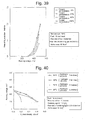
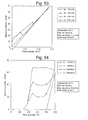
- FIG. 4 shows a graph for indicating relationship between the open-circuit voltage and the rate of hydrogen evolution, both adapted from the results of FIG. 3 .
- the rate of hydrogen evolution (volume of hydrogen evolution) tends to depend on the open-circuit voltage, and that hydrogen evolves when the open-circuit voltage is in the range of 400 to 600 mV.
- the rate of hydrogen evolution is the highest around 450 mV for all the temperatures tested.
- the gas contains hydrogen at about 70%, and carbon dioxide at about 15%. CO was not detected.
- the same hydrogen generating cell as that of hydrogen generating example 1-1 was used.
- the temperature of the cell was kept at 70°C, and 1M aqueous solution of methanol (fuel) was applied at the flow rate of 2, 8, or 15 ml/min.
- 1M aqueous solution of methanol (fuel) was applied at the flow rate of 2, 8, or 15 ml/min. Then, relations of the flow rate of fuel, the flow rate of air, the rate of hydrogen evolution and open-circuit voltage with the flow rate of air were shown in FIG. 5 .
- FIG. 6 shows a graph for indicating relationship between the open-circuit voltage and the rate of hydrogen evolution, both adapted from the results of FIG. 5 .
- the highest rate of hydrogen evolution 14.48 ml/min was obtained at the open-circuit voltage of 442 mV (operation temperature: 70°C; concentration of fuel: 1M; flow rate of fuel: 2 ml/min; and flow rate of air: 100 ml/min).
- concentration of hydrogen in the evolved gas was determined by gas chromatography as in example 1-1, and found to be about 70%.
- the same hydrogen generating cell as that of hydrogen generating example 1-1 was used.
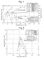
- the temperature of the cell was kept at 70°C, and aqueous solution of methanol (fuel) at a fuel concentration of 0.5, 1 or 2M was applied at a constant flow rate of 8 ml/min.
- aqueous solution of methanol (fuel) at a fuel concentration of 0.5, 1 or 2M was applied at a constant flow rate of 8 ml/min.
- relations of the flow rate of fuel, the flow rate of air, the rate of hydrogen evolution and open-circuit voltage with the flow rate of air were shown in FIG. 7 .
- FIG. 8 shows a graph for indicating relationship between the open-circuit voltage and the rate of hydrogen evolution, both adapted from the results of FIG. 7 .
- the rate of hydrogen evolution depends on the open-circuit voltage, and that hydrogen evolves when the open-circuit voltage is in the range of 300 to 600 mV.
- the rate of hydrogen evolution is the highest around 450 mV for all the fuel concentrations tested as in hydrogen generating example 1-1.
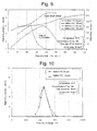
- the hydrogen generating cell was constructed similarly to the above examples, using a Nafion 112 (Dupont) having a thickness of 50 ⁇ m, instead of Nafion 115 (Dupont) having a thickness of 130 ⁇ m as used in the above examples 1-1 to 1-3.
- the cell was operated: temperature at 70°C; concentration of fuel at 1M; and flow rate of fuel at 8 ml/min, and relations of the flow rate of fuel, the flow rate of air and the rate of hydrogen evolution with the flow rate of air were studied.
- Both Nafion 115 and 112 membranes are made of the same material as a single difference in their thickness. Thus, only the thickness of electrolyte membranes serves as a parameter to be studied in the experiment. The study results are summarized in FIG. 9 .
- FIG. 10 shows a graph for indicating relationship between the open-circuit voltage and the rate of hydrogen evolution, both adapted from the results of FIG. 9 .
- the rate of hydrogen evolution was similar regardless of the thickness of electrolyte membrane. As seen from the figure, the rate of hydrogen evolution depends on the open-circuit voltage, and is the highest around 450 mV.
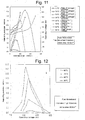
- a hydrogen generating cell constructed as in hydrogen generating example 1-1 was placed in an electric furnace where hot air was circulated.
- the temperature of the cell was kept at 30, 50, 70, or 90°C, air was flowed at a rate of 0 to 250 ml/min to the air electrode, and 1M aqueous solution of methanol was flowed at a rate of 5 ml/min to the fuel electrode. Then, the open-circuit voltage, and the rate of hydrogen evolution from the fuel electrode were monitored and analyzed.
- FIG. 12 shows a graph for indicating relationship between the open-circuit voltage and the rate of hydrogen evolution, both adapted from the results of FIG. 11 .
- the rate of hydrogen evolution depends on the open-circuit voltage, and hydrogen evolves when the open-circuit voltage is in the range of 300 to 7 00 mV.
- the rate of hydrogen evolution is the highest around 470 to 480 mV when the temperature is kept at 30 to 70°C, while the peak is shifted to 440 mV when the temperature is raised to 90°C.
- the same hydrogen generating cell as that of hydrogen generating example 1-1 was used.
- the temperature of cell was kept at 50°C, and fuel was applied at the flow rate of 1.5, 2.5, 5.0, 7.5, or 10.0 ml/min.
- relations of the flow rate of fuel, the flow rate of air and the rate of hydrogen evolution, with the flow rate of air were shown in FIG. 13 .
- FIG. 14 shows a graph for indicating relationship between the open-circuit voltage and the rate of hydrogen evolution, both adapted from the results of FIG. 13 .
- the rate of hydrogen evolution depends on the open-circuit voltage, and hydrogen evolves when the open-circuit voltage is in the range of 300 to 700 mV.
- the rate of hydrogen evolution is the highest around 450 to 500 mV.
- the energy efficiency under open-circuit condition was determined by calculation in accordance with the equation described below (which is different from the equation used for determining the energy efficiency of a charging condition). As a result it was found that, under open-circuit condition, the energy efficiency was 17% when fuel flows at 5.0 ml/min, and 22% when fuel flows at 2.5 ml/min.
- the same hydrogen generating cell as that of hydrogen generating example 1-1 was used.
- the temperature of cell was kept at 50°C, and aqueous solution of methanol (fuel) was applied at a constant flow rate of 5 ml/min while the concentration of fuel was varied to 0.5, 1, 2, 3M.
- aqueous solution of methanol (fuel) was applied at a constant flow rate of 5 ml/min while the concentration of fuel was varied to 0.5, 1, 2, 3M.
- relations of the flow rate of air and the rate of hydrogen evolution with the flow rate of air were shown in FIG. 15 .
- FIG. 16 shows a graph for indicating relationship between the open-circuit voltage and the rate of hydrogen evolution, both adapted from the results of FIG. 15 .
- the same hydrogen generating cell as that of hydrogen generating example 1-1 was used (except that the air electrode consisted of an oxidizing electrode to which oxidizing gas was flowed) .
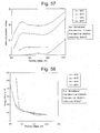
- the cell was operated: temperature at 50°C; concentration of fuel at 1M; and flow rate of fuel at 5 ml/min, while the concentration of oxygen being varied to 10, 21, 40, or 100% and relations of the open-circuit voltage and the rate of hydrogen evolution with the flow rate of oxidizing gas were studied.
- the results are shown in FIG, 17 .
- the oxidizing gas containing 21% oxygen was represented by air, and the oxidizing gas containing 10% oxygen was obtained by mixing air with nitrogen.
- the oxidizing gas containing 40% oxygen was obtained by adding oxygen (100% oxygen) to air.
- FIG. 18 shows a graph for indicating relationship between the open-circuit voltage and the rate of hydrogen evolution, both adapted from the results of FIG. 17 .
- the rate of hydrogen evolution depends on the open-circuit voltage, and hydrogen evolves when the open-circuit voltage is in the range of 400 to 800 mV.
- the rate of hydrogen evolution is the highest at 490 to 530 mV.
- the same hydrogen generating cell as that of hydrogen generating example 1-1 was used.
- the cell was operated at 50°C with the flow of air to the air electrode kept at 60 ml/min and the flow of aqueous solution of methanol (fuel) to the fuel electrode kept at 2.6 ml/min to cause gas to evolve.
- a 200 cc of sample was collected from the gas, and the concentration of CO of the gas was determined by gas chromatography. No CO was detected in the gas (1 ppm or lower) .
- the open-circuit voltage of the cell wan 477 mV and the rate of hydrogen evolution was 10 ml/min.
- Example 1-1 The same hydrogen generating cell with that of Example 1-1 was used (except that the air electrode consisted of an oxidizing electrode to which liquid hydrogen peroxide was flowed).
- the cell was placed in an electric furnace where hot air was circulated.
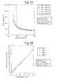
- the cell was operated while the temperature being kept at 30, 50, 70, or 90°C with the flow of 1M H 2 O 2 (hydrogen peroxide) to the oxidizing electrode kept at 1 - 8 ml/min and the flow of 1M aqueous solution of methanol (fuel) to the fuel electrode kept at 5 ml/min.
- Relations of the open-circuit voltage and the rate of hydrogen evolution with the flow rate of hydrogen peroxide were studied.
- FIG. 20 shows a graph for indicating relationship between the open-circuit voltage and the rate of hydrogen evolution, both adapted from the results of FIG. 19 .
- the rate of hydrogen evolution depends on the open-circuit voltage, and hydrogen evolves when the open-circuit voltage is in the range of 300 to 600 mV.
- the rate of hydrogen evolution is the highest around 500 mV when the temperature is kept at 30 to 50 °C, while the peak is shifted to 450 mV when the temperature is raised to 70 to 90°C.
- Example 1 What is important here is that no current or voltage was applied from outside to the hydrogen generating cells of Example 1.
- the cell was only connected to an electrometer for monitoring the open-circuit voltage which has an internal impedance of 1 G ⁇ or higher, while the cell was supplied with fuel and oxidizing agent.
- the hydrogen generating cell of Example 1 converted part of fuel into hydrogen receiving no external energy except for fuel and oxidizing agent.
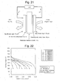
- Example 2 The structure of hydrogen generating cells described in Example 2 (illustrative examples 2-1 to 2-8) with a means for withdrawing electric energy is outlined in FIG. 21 .
- the hydrogen generating cells of Example 2 are the same in structure as those of hydrogen generating example 1-1 except that the cell comprises a fuel electrode as a negative electrode and an air electrode as a positive electrode-with a means for withdrawing electric energy.
- the hydrogen generating cell was placed in an electric furnace where hot air was circulated.
- the cell was operated while the temperature (operation temperature) being kept at 50°C with the flow rate of air to the air electrode kept at 10 to 100 ml/min and the flow of 1M aqueous solution of methanol (fuel) to the fuel electrode kept at 5 ml/min to cause gas to evolve.
- the external current flowing between the air electrode and the fuel electrode being varied, the operation voltage between the fuel electrode and the air electrode, the volume of gas evolved from the fuel electrode and gas composition were monitored and analyzed.
- the concentration of hydrogen in the generated gas was determined by gas chromatography.
- FIG. 23 shows a graph for indicating relationship between the rate of hydrogen evolution, and the operation voltage, both adapted from the results of FIG. 22 .
- the rate of hydrogen evolution (volume of hydrogen evolution) depends on the operation voltage, and gas evolves when the operation voltage is in the range of 300 to 600 mV. Moreover, when the flow rate of air is in the range of 50 to 60 ml/min, hydrogen evolves most readily: when the flow rate of air is excessively large as 100 ml/min, no evolution of hydrogen is detected.
- the cell was operated: temperature at 50°C; flow rate of fuel at 5 ml/min; flow rate of air at 60 ml/min; and current density at 8.4 mA/cm 2 to cause gas to evolve.
- concentration of hydrogen in the gas was determined by gas chromatography.
- the gas contained hydrogen at about 74%, and hydrogen evolved at a rate of 5.1 ml/min. No CO was detected.
- the same hydrogen generating cell as that of hydrogen generating example 2-1 was used.
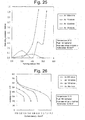
- the cell was operated while the temperature being kept at 30°C with the flow rate of air to the air electrode kept at 30 through 100 ml/min and the flow of 1M aqueous solution of methanol (fuel) to the fuel electrode kept at 5 ml/min. Then, while the current flowing between the air electrode and the fuel electrode being varied, the operation voltage between the fuel electrode and the air electrode, and the rate of hydrogen evolution occurring from the fuel electrode were monitored and analyzed.
- FIG. 25 shows a graph for indicating relationship between the rate of hydrogen evolution and the operation voltage, both adapted from the results of FIG. 24 .
- the same hydrogen generating cell as that of hydrogen generating example 2-1 was used.
- the cell was operated while the temperature being kept at 70°C with the flow rate of air to the air electrode kept at 50 - 200 ml/min and the flow of 1M aqueous solution of methanol (fuel) to the fuel electrode kept at 5 ml/min. Then, while the current flowing between the air electrode and the fuel electrode being varied, the operation voltage between the fuel electrode and the air electrode, and the rate of hydrogen evolution occurring from the fuel electrode were monitored and analyzed.
- FIG. 27 shows a graph for indicating relationship between the rate of hydrogen evolution and the operation voltage, both adapted from the results of FIG. 26 .
- the same hydrogen generating cell as that of hydrogen generating example 2-1 was used.
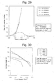
- the cell was operated while the temperature being kept at 90°C with the flow of air to the air electrode kept at 50 through 250 ml/min and the flow of 1M aqueous solution of methanol (fuel) to the fuel electrode kept at 5 ml/min. Then, while the current flowing between the air electrode and the fuel electrode being varied, the operation voltage between the fuel electrode and the air electrode, and the rate of hydrogen evolution occurring from the fuel electrode were monitored and analyzed.
- FIG. 29 shows a graph for indicating relationship between the rate of hydrogen evolution and the operation voltage, both adapted from the results of FIG. 28 .
- FIG. 30 shows relation of the current density withdrawn with the operation voltage while FIG. 31 shows relation of the rate of hydrogen evolution with the operation voltage.
- FIG. 32 shows relation of the current density withdrawn with the operation voltage while FIG. 33 shows relation of the rate of hydrogen evolution with the operation voltage.
- the same hydrogen generating cell as that of hydrogen generating example 2-1 was used.
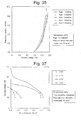
- the cell was operated while the temperature being kept at 50°C with the flow of air to the air electrode kept at 50 ml/min and the flow rate of fuel to the fuel electrode varied to 1.5, 2.5, 5.0, 7.5, or 10.0 0 ml/min. Then, while the current flowing between the air electrode and the fuel electrode being varied, the operation voltage between the fuel electrode and the air electrode, and the rate of hydrogen evolution occurring from the fuel electrode were monitored and analyzed.
- FIG. 35 shows a graph for indicating relationship between the rate of hydrogen evolution and the operation voltage, both adapted from the results of FIG. 34 .
- the rate of hydrogen evolution depends on the operation voltage, and hydrogen evolves when the operation voltage is in the range of 300 to 500 mV.
- the rate of hydrogen evolution is high when the operation voltage is in the range of 450 to 500 ml/min.
- the same hydrogen generating cell as that of hydrogen generating example 2-1 was used.
- the cell was operated while the temperature being kept at 50°C with the flow of air to the air electrode kept at 50 ml/min and the constant flow of fuel to the fuel electrode kept at 5 ml/min while fuel concentration being varied to 0. 5, 1, 2, or 3M. Then, while the current flowing between the air electrode and the fuel electrode being varied, the operation voltage between the fuel electrode and the air electrode, and the rate of hydrogen evolution occurring from the fuel electrode were monitored and analyzed.
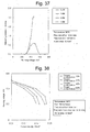
- FIG. 37 shows a graph for indicating relationship between the rate of hydrogen evolution and the operation voltage, both adapted from the results of FIG. 36.
- the same hydrogen generating cell as that of hydrogen generating example 2-1 was used (except that the air electrode consisted of an oxidizing electrode to which oxygen was flowed).
- the cell was operated while the temperature being kept at 50°C with the flow of oxidizing gas to the oxidizing electrode kept at 14.0 ml/min and the constant flow of 1M fuel concentration to the fuel electrode kept at 5 ml/min, while the concentration of oxygen being varied to 10, 21, 40, or 100%.
- the oxidizing gas containing 21% oxygen was represented by air, and the oxidizing gas containing 10% oxygen was obtained by mixing air with nitrogen.
- the oxidizing gas containing 40% oxygen was obtained by adding oxygen (100% oxygen concentration) to air.
- FIG. 39 shows a graph for indicating relationship between the rate of hydrogen evolution and the operation voltage, both adapted from the results of FIG. 38 .
- the rate of hydrogen evolution tends to be high as the concentration of oxygen becomes higher.
- the same hydrogen generating cell as that of hydrogen generating example 2-1 was used (except that the air electrode consisted of an oxidizing electrode to which liquid hydrogen peroxide was flowed).
- the hydrogen generating cell was placed in an electric furnace where hot air was circulated.
- the cell was operated while the temperature being varied to 30, 50, 70, or 90°C with the flow of 1M aqueous solution of H 2 O 2 (hydrogen peroxide) to the oxidizing electrode varied from 2.6 to 5.5 ml/min, and the flow of 1M aqueous solution of methanol (fuel) to the fuel electrode kept at 5 ml/min.
- FIG. 41 shows a graph for indicating relationship between the rate of hydrogen evolution and the operation voltage, both adapted from the results of FIG. 40 .
- the hydrogen generating cell of Example 2 converted part of fuel into hydrogen while withdrawing electric energy to outside.
- reforming occurred at a surprisingly low temperature of 30 to 90°C.
- the hydrogen generating device of the invention is likely to be novel and the effect to use this hydrogen generating device in the package-type fuel cell power generating device incorporating the control device requiring protection from high heat is profound.
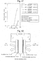
- Example 3 The structure of hydrogen generating cells described in Example 3 (hydrogen generating examples 3-1 to 3-8) with a means for providing electric energy from outside is outlined in FIG. 42 .
- the hydrogen generating cells are the same in structure as those of hydrogen generating example 1-1 except that the cell comprises a fuel electrode as cathode and an oxidizing electrode as anode with a means for providing electric energy from outside.
- the hydrogen generating cell was placed in an electric furnace where hot air was circulated.
- the cell was operated while the temperature (operation temperature) being kept at 50°C with the flow of air to the air electrode kept at 10 to 80 ml/min and the flow of 1M aqueous solution of methanol (fuel) to the fuel electrode kept at 5 ml/min.
- the current flowing between the air electrode and the fuel electrode being varied by means of a DC power source from outside
- the operation voltage between the fuel electrode and the air electrode the volume of gas evolved from the fuel electrode and gas composition were monitored and analyzed.
- the energy efficiency of charging condition was defined as a ratio of the chemical energy of hydrogen evolved to the electric energy supplied from outside.
- the concentration of hydrogen in the generated gas was determined by gas chromatography, and rate of hydrogen evolution also determined.
- the object of this invention lies in obtaining hydrogen gas having a higher energy content than the electric energy supplied from outside, and the invention does not aim to gain more energy than the sum of paid energy without taking any heed to the law of conservation of energy taught by thermodynamics.
- the energy expenditure includes, in addition to the electric energy supplied from outside, the chemical energy consumed for the oxidization of the fuel, which will amount to a value equal to or less than 100%.
- the inventive method from conventional methods for obtaining hydrogen via the electrolysis of water, the energy efficiency of a system defined by the ratio of the chemical energy of evolved hydrogen to the electric energy supplied from outside will be used here.
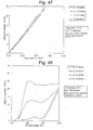
- FIG. 44 shows a graph for indicating relationship between the rate of hydrogen evolution and the operation voltage, both adapted from the results of FIG. 43 .
- the rate of hydrogen evolution (volume of hydrogen evolution) tends to depend on the operation voltage, and hydrogen evolves when the operation voltage is equal to or larger than 400 mV, and the rate of hydrogen evolution becomes virtually constant when the operation voltage becomes equal to or larger than 600 mV, and the rate of hydrogen evolution becomes larger (hydrogen is readier to evolve) with reduction of the flow rate of air.
- the energy efficiency is equal to or larger than 100% even when the operation voltage is around 1000 mV, and the energy efficiency is particularly high when the operation voltage is kept equal to or smaller than 600 mV, and the flow of air is kept at 30 to 50 ml/min.
- the cell was operated under a condition of high energy efficiency (1050%): temperature at 50°C; flow rate of fuel at 5 ml/min; flow rate of air at 50 ml/min; and current density at 4.8 mA/cm 2 to cause gas to evolve.
- concentration of hydrogen in the gas was determined by gas chromatography. As a result it was found that the gas contained hydrogen at about 86%, and hydrogen evolved at a rate of 7.8 ml/min. No CO was detected.
- the same hydrogen generating cell as that of hydrogen generating example 3-1 was used.
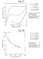
- the cell was operated while the temperature being kept at 30°C with the flow of air to the air electrode varied from 10 to 70 ml/min and the flow of 1M aqueous solution of methanol (fuel) to the fuel electrode kept at 5 ml/min. Then, while the current flowing between the air electrode and the fuel electrode being varied by means of a DC power source from outside, the operation voltage between the fuel electrode and the air electrode, the rate of hydrogen evolution occurring from the fuel electrode, and the energy efficiency were monitored and analyzed.
- the rate of hydrogen evolution tends to depend on the operation voltage, and hydrogen evolves when the operation voltage is equal to or larger than 400 mV; hydrogen is readier to evolve with reduction of the flow rate of air; and the rate of hydrogen evolution becomes virtually constant with the air flow of 10 ml/min, when the operation voltage becomes equal to or larger than 600 mV, while the rate of hydrogen evolution tends to grow with the air flow of 30 ml/min, when the operation voltage becomes equal to or larger than 800 mV, and thus no hydrogen will evolve when air flows at a higher rate unless the operation voltage is raised sufficiently high.
- the energy efficiency is equal to or larger than 100% even when the operation voltage is around 1000 mV, and the energy efficiency is particularly high with the air flow of 30 ml/min when the operation voltage is kept equal to or smaller than 600 mV.
- the test was performed under the same condition as in hydrogen generating example 3-2 except that the temperature of the cell was kept at 70°C.
- the operation voltage between the fuel electrode and the air electrode, and rate of hydrogen evolution on the fuel electrode and energy efficiency were monitored and analyzed.
- the rate of hydrogen evolution tends to depend on the operation voltage, and hydrogen evolves when the operation voltage is equal to or larger than 400 mV; hydrogen is readier to evolve with reduction of the flow rate of air; and the rate of hydrogen evolution becomes virtually constant with the air flow of 10 ml/min, when the operation voltage becomes equal to or larger than 600 mV, while the rate of hydrogen evolution tends to grow with the air flow of 30 ml/min, when the operation voltage becomes equal to or larger than 800 mV, and thus no hydrogen will evolve when air flows at a higher rate unless the operation voltage is raised sufficiently high.
- the energy efficiency is equal to or larger than 100% even when the operation voltage is around 1000 mV, and the energy efficiency is particularly high with the flow rate of air of 10 to 30 ml/min when the operation voltage is kept equal to or smaller than 600 mv.
- the same hydrogen generating cell as that of hydrogen generating example 3-1 was used.
- the cell was operated while the temperature being kept at 90°C with the flow rate of air to the air electrode varied from 10 to 200 ml/min and the flow of 1M aqueous solution of methanol (fuel) to the fuel electrode kept at 5 ml/min. Then, while the current flowing between the air electrode and the fuel electrode being varied by means of a DC power source from outside, the operation voltage between the fuel electrode and the air electrode, the rate of hydrogen evolution occurring from the fuel electrode, and the energy efficiency were monitored and analyzed.
- the rate of hydrogen evolution tends to depend on the operation voltage, and hydrogen evolves when the operation voltage is equal to or larger than 300 mV; hydrogen is readier to evolve with reduction of the flow rate of air; and the rate of hydrogen evolution becomes virtually constant with the air flow of 10 ml/min, when the operation voltage becomes equal to or larger than 500 mV, while the rate of hydrogen evolution tends to grow with the air flow of 50 to 100 ml/min, when the operation voltage becomes equal to or larger than 800 mV, and thus no hydrogen will evolve when air flows at 200 ml/min unless the operation voltage is raised higher than 800 mV.
- the energy efficiency is equal to or larger than 100% even when the operation voltage is around 1000 mV, and the energy efficiency is particularly high with the flow of air of 50 ml/min when the operation voltage is kept equal to or smaller than 500 mV.
- the energy efficiency is equal to or larger than 100% even when the operation voltage is around 1000 mV, and the energy efficiency is particularly high when the operation voltage is kept equal to or smaller than 600 mV.
- the same hydrogen generating cell with that of hydrogen generating example 3-1 was used.
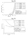
- the cell was operated while the temperature being kept at 50°C with the flow of air to the air electrode kept at 50 ml/min and the flow of fuel to the fuel electrode varied to 1.5, 2.5, 5.0, 7.5, or 10.0 ml/min. Then, while the current flowing between the air electrode and the fuel electrode being varied by means of a DC power source from outside, the operation voltage between the fuel electrode and the air electrode, the rate of hydrogen evolution occurring from the fuel electrode, and the energy efficiency were monitored and analyzed.
- Relation of the rate of hydrogen evolution with the current density applied is shown in FIG. 59
- relation of the rate of hydrogen evolution with the operation voltage is shown in FIG. 60 .
- the rate of hydrogen evolution tends to depend on the operation voltage, and hydrogen evolves when the operation voltage is equal to or larger than 400 mV; hydrogen is readier to evolve with increase of the flow rate of fuel; and the rate of hydrogen evolution tends to grow when the operation voltage is equal to or larger than 800 mV for all the flow rates of fuel tested.
- the energy efficiency is equal to or larger than 100% even when the operation voltage is around 1000 mV, and the energy efficiency is particularly high when the operation voltage is kept equal to or smaller than 600 mV.
- the same hydrogen generating cell as that of hydrogen generating example 3-1 was used.
- the cell was operated while the temperature being kept at 50°C with the flow of air to the air electrode kept at 50 ml/znin and the constant flow of fuel to the fuel electrode kept at 5ml/min while fuel concentration being varied to 0.5, 1, 2, or 3M. Then, while the external current flowing between the air electrode and the fuel electrode being varied by means of a DC power source from outside, the operation voltage between the fuel electrode and the air electrode, the rate of hydrogen evolution occurring from the fuel electrode, and the energy efficiency were monitored and analyzed.
- Relation of the rate of hydrogen evolution with the current density applied is shown in FIG. 62
- relation of the rate of hydrogen evolution with the operation voltage is shown in FIG. 63 .
- the rate of hydrogen evolution tends to depend on the operation voltage, and hydrogen evolves when the operation voltage is equal to or larger than 400 mV; hydrogen is readier to evolve with increase of the concentration of fuel, and the rate of hydrogen evolution grows sharply under the fuel concentration of 2M or 3M, when the operation voltage approaches 400 to 500 mV; and the rate of hydrogen evolution becomes virtually constant under the fuel concentration of 1M when the operation voltage is in the range of 400 to 800 mV, while the rate of hydrogen evolution tends to grow when the operation voltage becomes equal to or larger than 800 mV, and no hydrogen will evolve when the fuel concentration is lower than this level (1M) unless the operation voltage is raised sufficiently high.
- the energy efficiency is equal to or larger than 100% even when the operation voltage is around 1000 mV except for a case where the fuel concentration is kept at 0.5M, and the energy efficiency is particularly high with the concentration of the fuel being 1, 2 or 3M when the operation voltage is kept equal to or smaller than 600 mV.
- concentration of fuel was 0.5M, no hydrogen evolved when the operation voltage was low. Under this condition, the cell behaved quite differently in terms of energy efficiency.
- the same hydrogen generating cell with that of hydrogen generating example 3-1 was used (except that the air electrode consisted of an oxidizing electrode to which oxidizing gas was flowed) .
- the cell was operated while the temperature being kept at 50°C with the constant flow of 1M fuel to the fuel electrode kept at 5 ml/min and the flow of oxidizing gas to the oxidizing electrode kept at 14.0 ml/min while oxygen concentration being varied to 10, 21, 40, or 100%.
- the current flowing between the oxidizing electrode and the fuel electrode being varied by means of a DC power source from outside
- the oxidizing gas containing 21% oxygen was represented by air
- the oxidizing gas containing 10% oxygen was obtained by mixing air with nitrogen.
- the oxidizing gas containing 40% oxygen was obtained by adding oxygen (100% oxygen) to air.
- the rate of hydrogen evolution tends to depend on the operation voltage, and hydrogen evolves when the operation voltage is equal to or larger than 400 mV; hydrogen is readier to evolve with increase of the concentration of oxygen; and the rate of hydrogen evolution becomes virtually constant under when the operation voltage is in the range of 400 to 800 mV, while it tends to grow when the operation voltage becomes equal to or larger than 800 mV.
- the energy efficiency is equal to or larger than 100% even when the applied voltage is around 1000 mV, and the energy efficiency is particularly high with the concentration of oxygen being high when the applied voltage is kept equal to or smaller than 600 mV.
- the same hydrogen generating cell as that of hydrogen generating example 3-1 was used (except that the air electrode consisted of an oxidizing electrode to which liquid hydrogen peroxide was flowed).
- the hydrogen generating cell was placed in an electric furnace where hot air was circulated. The cell was operated while the temperature being varied to 30, 50, 70, or 90°C with the flow of 1M aqueous solution of methanol to the fuel electrode kept at 5 ml/min and the flow of 1M H2O 2 (hydrogen peroxide) to the oxidizing electrode varied from 2.6 to 5.5 ml/min.
- the flow rate of hydrogen peroxide was adjusted such that the open-circuit voltage was approximately equal to 500 a-cGV for all the temperatures tested.
- the energy efficiency is equal to or larger than 100% even when the operation voltage is around 1000 mV, and the energy efficiency is particularly high with the temperature of 90 °C when the operation voltage is kept equal to or smaller than 800 mV.
- Hydrogen was generated by the hydrogen generating device of the present invention as described in Claim 4 of the invention (open circuit condition) using ethanol as a fuel.
- the flow rate of 1M aqueous solution of ethanol was made at 5ml/min to flow to the fuel electrode and the flow rate of air was made at 65 ml/min to the air electrode.
- the open-circuit voltage of the cell and the rate of gas evolution generated from the fuel electrode were measured.
- the hydrogen concentration in the generated gas was analyzed by a gas chromatography and the hydrogen evolution rate was acquired.
- Table 1 Air Open-circuit voltage Gas evolution rate H 2 concentration H 2 evolution rate /ml/min /mV /ml /min /% /ml/min 65 478 0.6 65.2 0.39
- Hydrogen was generated by the hydrogen generating device of the present invention as described in Claim 4 of the invention (open circuit condition) using ethylene glycol as a fuel.
- the same hydrogen generating cell as that of hydrogen generating example 1-1 was used.
- the flow rate of 1M aqueous solution of ethylene glycol was made at 5 ml/min to flow to the fuel electrode and the flow rate of air was made at 105 ml/min to the air electrode.
- the open-circuit voltage of the cell and the rate of gas evolution generated from the fuel electrode were measured.
- the hydrogen concentration in the generated gas was analyzed by a gas chromatography and the hydrogen evolution rate was acquired.
- Table 2 Air Open-circuit voltage Gas evolution rate H 2 concentration H 2 evolution rate /ml/min /mV /ml/min /% /ml/min 105 474 2.4 88.4 2.12
- Hydrogen was generated by the hydrogen generating device of the present invention as described in Claim 4 of the invention (open circuit condition) using 2-propanol as a fuel.
- the same hydrogen generating cell as that of hydrogen generating example 1-1 was used.
- the flow rate of 1M aqueous solution of 2-propanol was made at 5 ml/min to flow to the fuel electrode and the flow rate of air was made at 35 ml/min to the air electrode.
- the open-circuit voltage of the cell and the rate of gas evolution generated from the fuel electrode were measured.
- the hydrogen concentration in the generated gas was analyzed by a gas chromatography and the hydrogen evolution rate was acquired.
- Table 3 Air Open-circuit voltage Gas evolution rate H 2 concentration H 2 evolution rate /ml/min /mV /ml/min /% /ml/min 35 514 3.96 95.6 3.78
- Hydrogen was generated by the hydrogen generating device of the present invention as described in Claim 4 of the invention (open circuit condition) using diethyl ether as a fuel.
- the same hydrogen generating cell as that of hydrogen generating example 1-1 was used.
- the flow rate of 1M aqueous solution of diethyl ether was made at 5 ml/min to flow to the fuel electrode and the flow rate of air was made at 20 ml/min to the air electrode.
- the open-circuit voltage of the cell and the rate of gas evolution generated from the fuel electrode were measured.
- the hydrogen concentration in the generated gas was analyzed by a gas chromatography and the hydrogen evolution rate was acquired.
- Table 4 Air Open-circuit voltage Gas evolution rate H 2 concentration H 2 evolution rate /ml/min /mV /ml/min /% /ml/min 20 565 3.0 7.6 0.23
- Hydrogen was generated by the hydrogen generating device of the present invention as described in Claim 4 of the invention (open circuit condition) using formaldehyde, formic acid as a fuel.
- the same hydrogen generating cell as that of hydrogen generating example 1-1 was used.
- the flow rate of 1M aqueous solution of formaldehyde, the flow rate of 1M aqueous solution of formic acid were made at 5 ml/min respectively to flow to the fuel electrode and the flow of air was made at 0 to 100 ml/min to the air electrode.
- the open-circuit voltage of the cell and the rate of gas evolution generated from the fuel electrode were measured.
- the hydrogen concentration, in the generated gas was analyzed by a gas chromatography and the hydrogen evolution rate was acquired.
- the hydrogen evolution rate (hydrogen evolution volume) also tends to depend on the open-circuit voltage as with methanol and that hydrogen was generated at the open-circuit voltage of 200 to 800 mV.
- hydrogen was generated in a state where the open-circuit voltage was lower than that for methanol, formaldehyde.
- the peak of hydrogen evolution rate was observed at a low open-circuit voltage (about 350 mV) for formic acid, while that of methanol, formaldehyde was about 500 mV.
- Hydrogen was generated by the hydrogen generating cell used in the hydrogen generating device of the present invention as described in Claims 3 and 4 of the invention (open circuit condition) by changing the structure of the hydrogen generating cell.
- the same hydrogen generating cell as that of hydrogen generating example 1-1 was used to produce the hydrogen generating cell except that only the air electrode separator board is combined with MEA except the fuel electrode separator board of the separator boards.
- the hydrogen generating cell produced as above was used.
- the flow rate of 1M aqueous solution of methanol was made at 5 ml/min to flow to the fuel electrode and the flow rate of air was made at 0 to 150 ml/min to the air electrode.
- the open-circuit voltage of the cell and the rate of gas evolution generated from the fuel electrode were measured.
- the hydrogen concentration in the generated gas was analyzed by a gas chromatography and the hydrogen evolution rate was acquired.
- Hydrogen was generated at the air flow rate of 30 to 130 ml/min, but the hydrogen evolution volume was lower than the case where the separator board is used for both the fuel electrode and the air electrode.
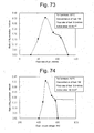
- FIG. 73 The result of FIG. 73 is shown as relation of relation of the rate of hydrogen evolution with the open-circuit voltage in FIG. 74 .
- the hydrogen evolution rate (hydrogen evolution volume) shows a tendency to depend on the open-circuit voltage as that of hydrogen generating example 1-1, and hydrogen is found to be generated at the open-circuit voltage of 400 to 600 mV. Also, the peak of the hydrogen evolution rate is observed in the vicinity of 470 mV.
- a hydrogen generating device can generate hydrogen-containing gas by decomposing fuel containing an organic compound at temperature not higher than 100°C and supply hydrogen to a fuel cell, a hydrogen storage container or the like without difficulty.
- a hydrogen generating device can highly advantageously find applications in electric automobiles, submarines, hydrogen supply systems, package type fuel cell power generating device and so on.
Landscapes
- Chemical & Material Sciences (AREA)
- Engineering & Computer Science (AREA)
- Chemical Kinetics & Catalysis (AREA)
- General Chemical & Material Sciences (AREA)
- Sustainable Energy (AREA)
- Sustainable Development (AREA)
- Manufacturing & Machinery (AREA)
- Electrochemistry (AREA)
- Life Sciences & Earth Sciences (AREA)
- Organic Chemistry (AREA)
- Health & Medical Sciences (AREA)
- General Health & Medical Sciences (AREA)
- Combustion & Propulsion (AREA)
- Inorganic Chemistry (AREA)
- Fuel Cell (AREA)
- Hydrogen, Water And Hydrids (AREA)
Applications Claiming Priority (3)
| Application Number | Priority Date | Filing Date | Title |
|---|---|---|---|
| JP2005192175 | 2005-06-30 | ||
| JP2005359437A JP4958059B2 (ja) | 2005-06-30 | 2005-12-13 | 水素製造装置 |
| PCT/JP2006/313528 WO2007004714A1 (ja) | 2005-06-30 | 2006-06-30 | 水素製造装置 |
Publications (2)
| Publication Number | Publication Date |
|---|---|
| EP1911721A1 true EP1911721A1 (de) | 2008-04-16 |
| EP1911721A4 EP1911721A4 (de) | 2012-02-22 |
Family
ID=37604571
Family Applications (1)
| Application Number | Title | Priority Date | Filing Date |
|---|---|---|---|
| EP06780853A Ceased EP1911721A4 (de) | 2005-06-30 | 2006-06-30 | Vorrichtung zur erzeugung von wasserstoff |
Country Status (5)
| Country | Link |
|---|---|
| US (1) | US20090169933A1 (de) |
| EP (1) | EP1911721A4 (de) |
| JP (1) | JP4958059B2 (de) |
| CN (1) | CN101208262B (de) |
| WO (1) | WO2007004714A1 (de) |
Families Citing this family (7)
| Publication number | Priority date | Publication date | Assignee | Title |
|---|---|---|---|---|
| JP5403198B2 (ja) * | 2005-06-03 | 2014-01-29 | 株式会社Gsユアサ | 水素製造装置、それを用いた燃料電池発電装置、電気自動車、潜水船及び水素供給システム |
| JP5403199B2 (ja) * | 2005-07-13 | 2014-01-29 | 株式会社Gsユアサ | ハニカム型水素製造装置、それを用いた燃料電池発電装置、電気自動車、潜水船及び水素供給システム、並びに水素製造セル用反応管 |
| WO2014031706A1 (en) * | 2012-08-20 | 2014-02-27 | Hydro Healer, Llc | Electrolysis system and apparatus for collecting hydrogen gas |
| JP5502973B1 (ja) * | 2012-11-30 | 2014-05-28 | ミズ株式会社 | 生体用高濃度水素ガス供給装置 |
| CN106698342A (zh) * | 2017-02-20 | 2017-05-24 | 樊品良 | 醇水制氢气设备 |
| JP2021507092A (ja) * | 2017-12-15 | 2021-02-22 | ザ・ボード・オブ・トラスティーズ・オブ・ザ・リーランド・スタンフォード・ジュニア・ユニバーシティ | 酸化炭素材料によって触媒される過酸化水素への高効率酸素還元 |
| CN112786934A (zh) * | 2019-11-11 | 2021-05-11 | 钱志刚 | 一种以甲醇为原料的磷酸燃料电池动力系统及其发电方法 |
Citations (3)
| Publication number | Priority date | Publication date | Assignee | Title |
|---|---|---|---|---|
| EP1698589A1 (de) * | 2003-12-26 | 2006-09-06 | GS Yuasa Corporation | Verfahren zur erzeugung von wasserstoff und dafür verwendete wasserstofferzeugungsvorrichtung |
| EP1837942A1 (de) * | 2004-12-28 | 2007-09-26 | GS Yuasa Corporation | Selbständiges wasserstoff-produktionssystem |
| EP1843424A1 (de) * | 2004-12-28 | 2007-10-10 | GS Yuasa Corporation | Brennstoffzellen-stromerzeugungseinrichtung |
Family Cites Families (12)
| Publication number | Priority date | Publication date | Assignee | Title |
|---|---|---|---|---|
| JPH0673582A (ja) * | 1992-08-27 | 1994-03-15 | Daicel Chem Ind Ltd | 炭酸ジエステルの製造方法および製造装置 |
| JP3456714B2 (ja) * | 1992-08-28 | 2003-10-14 | 三井化学株式会社 | メタノールの部分酸化物の製造方法 |
| JP3328993B2 (ja) * | 1993-05-10 | 2002-09-30 | 住友電気工業株式会社 | 水素発生方法 |
| US6299744B1 (en) | 1997-09-10 | 2001-10-09 | California Institute Of Technology | Hydrogen generation by electrolysis of aqueous organic solutions |
| US6387845B1 (en) * | 1999-03-23 | 2002-05-14 | Kabushiki Kaisha Toshiba | Carbon dioxide gas absorbent containing lithium silicate |
| EP1265303B1 (de) * | 2000-03-07 | 2009-07-01 | Panasonic Corporation | Polymer-elektroly-brennstoffzelle und herstellungsverfahren dafür |
| JP2001297779A (ja) * | 2000-04-13 | 2001-10-26 | Matsushita Electric Ind Co Ltd | 燃料電池システム |
| AU2001254921A1 (en) * | 2000-05-03 | 2001-11-12 | Zero-M Limited | Fuel system |
| DE10117572B4 (de) * | 2001-04-07 | 2005-10-13 | Ballard Power Systems Inc., Burnaby | Elektrochemischer Zellenstapel |
| WO2004049479A2 (en) * | 2002-11-27 | 2004-06-10 | Hydrogenics Corporation | An electrolyzer module for producing hydrogen for use in a fuel cell power unit |
| JP4081432B2 (ja) * | 2003-12-22 | 2008-04-23 | 本田技研工業株式会社 | 燃料電池 |
| US7524575B2 (en) * | 2004-06-07 | 2009-04-28 | Hyteon Inc. | Flow field plate for use in fuel cells |
-
2005
- 2005-12-13 JP JP2005359437A patent/JP4958059B2/ja not_active Expired - Fee Related
-
2006
- 2006-06-30 WO PCT/JP2006/313528 patent/WO2007004714A1/ja active Application Filing
- 2006-06-30 EP EP06780853A patent/EP1911721A4/de not_active Ceased
- 2006-06-30 CN CN2006800231813A patent/CN101208262B/zh not_active Expired - Fee Related
- 2006-06-30 US US11/988,034 patent/US20090169933A1/en not_active Abandoned
Patent Citations (3)
| Publication number | Priority date | Publication date | Assignee | Title |
|---|---|---|---|---|
| EP1698589A1 (de) * | 2003-12-26 | 2006-09-06 | GS Yuasa Corporation | Verfahren zur erzeugung von wasserstoff und dafür verwendete wasserstofferzeugungsvorrichtung |
| EP1837942A1 (de) * | 2004-12-28 | 2007-09-26 | GS Yuasa Corporation | Selbständiges wasserstoff-produktionssystem |
| EP1843424A1 (de) * | 2004-12-28 | 2007-10-10 | GS Yuasa Corporation | Brennstoffzellen-stromerzeugungseinrichtung |
Non-Patent Citations (2)
| Title |
|---|
| See also references of WO2007004714A1 * |
| YE Q ET AL: "Electrochemical Reactions in a DMFC under Open-Circuit Conditions", ELECTROCHEMICAL AND SOLID-STATE LETTERS, IEEE SERVICE CENTER, PISCATAWAY, NJ, US, vol. 8, no. 1, 1 January 2005 (2005-01-01) , pages A52-A54, XP003002724, ISSN: 1099-0062, DOI: 10.1149/1.1836111 * |
Also Published As
| Publication number | Publication date |
|---|---|
| EP1911721A4 (de) | 2012-02-22 |
| JP2007039305A (ja) | 2007-02-15 |
| WO2007004714A1 (ja) | 2007-01-11 |
| CN101208262A (zh) | 2008-06-25 |
| CN101208262B (zh) | 2011-08-17 |
| US20090169933A1 (en) | 2009-07-02 |
| JP4958059B2 (ja) | 2012-06-20 |
Similar Documents
| Publication | Publication Date | Title |
|---|---|---|
| US8523964B2 (en) | Hydrogen generating device as well as fuel cell power generating device, electric automobile, sumbergible ship and hydrogen supply system using the same | |
| EP1911721A1 (de) | Vorrichtung zur erzeugung von wasserstoff | |
| EP1837942A1 (de) | Selbständiges wasserstoff-produktionssystem | |
| EP1843424A1 (de) | Brennstoffzellen-stromerzeugungseinrichtung | |
| US7476456B2 (en) | Submarine boat | |
| US8679687B2 (en) | Hydrogen generating method and hydrogen generating system based on the method | |
| JP3812586B2 (ja) | 水素供給システム | |
| JP4958058B2 (ja) | 燃料電池発電装置 | |
| JP3818313B2 (ja) | 潜水船 | |
| US7910252B2 (en) | Hydrogen supply system | |
| US7939210B2 (en) | Electric automobile | |
| JP4947338B2 (ja) | 独立型水素製造システム | |
| JP4811704B2 (ja) | パッシブ型水素製造装置及びこれを用いたパッケージ型燃料電池発電装置 | |
| JP4863099B2 (ja) | スタック型燃料電池発電装置 |
Legal Events
| Date | Code | Title | Description |
|---|---|---|---|
| PUAI | Public reference made under article 153(3) epc to a published international application that has entered the european phase |
Free format text: ORIGINAL CODE: 0009012 |
|
| 17P | Request for examination filed |
Effective date: 20080102 |
|
| AK | Designated contracting states |
Kind code of ref document: A1 Designated state(s): DE FR GB |
|
| RBV | Designated contracting states (corrected) |
Designated state(s): DE FR GB |
|
| DAX | Request for extension of the european patent (deleted) | ||
| RBV | Designated contracting states (corrected) |
Designated state(s): DE FR GB |
|
| RAP1 | Party data changed (applicant data changed or rights of an application transferred) |
Owner name: GS YUASA INTERNATIONAL LTD. |
|
| A4 | Supplementary search report drawn up and despatched |
Effective date: 20120120 |
|
| RIC1 | Information provided on ipc code assigned before grant |
Ipc: C01B 3/22 20060101AFI20120116BHEP Ipc: H01M 8/10 20060101ALI20120116BHEP Ipc: H01M 8/06 20060101ALI20120116BHEP Ipc: C01B 3/32 20060101ALI20120116BHEP |
|
| 17Q | First examination report despatched |
Effective date: 20120920 |
|
| RAP1 | Party data changed (applicant data changed or rights of an application transferred) |
Owner name: GS YUASA INTERNATIONAL LTD. |
|
| REG | Reference to a national code |
Ref country code: DE Ref legal event code: R003 |
|
| STAA | Information on the status of an ep patent application or granted ep patent |
Free format text: STATUS: THE APPLICATION HAS BEEN REFUSED |
|
| 18R | Application refused |
Effective date: 20151123 |