EP1911565A2 - Device for manufacturing composite pipes - Google Patents
Device for manufacturing composite pipes Download PDFInfo
- Publication number
- EP1911565A2 EP1911565A2 EP07018037A EP07018037A EP1911565A2 EP 1911565 A2 EP1911565 A2 EP 1911565A2 EP 07018037 A EP07018037 A EP 07018037A EP 07018037 A EP07018037 A EP 07018037A EP 1911565 A2 EP1911565 A2 EP 1911565A2
- Authority
- EP
- European Patent Office
- Prior art keywords
- section
- outer nozzle
- nozzle
- tube
- mold
- Prior art date
- Legal status (The legal status is an assumption and is not a legal conclusion. Google has not performed a legal analysis and makes no representation as to the accuracy of the status listed.)
- Withdrawn
Links
Images


Classifications
-
- B—PERFORMING OPERATIONS; TRANSPORTING
- B29—WORKING OF PLASTICS; WORKING OF SUBSTANCES IN A PLASTIC STATE IN GENERAL
- B29C—SHAPING OR JOINING OF PLASTICS; SHAPING OF MATERIAL IN A PLASTIC STATE, NOT OTHERWISE PROVIDED FOR; AFTER-TREATMENT OF THE SHAPED PRODUCTS, e.g. REPAIRING
- B29C48/00—Extrusion moulding, i.e. expressing the moulding material through a die or nozzle which imparts the desired form; Apparatus therefor
- B29C48/25—Component parts, details or accessories; Auxiliary operations
- B29C48/88—Thermal treatment of the stream of extruded material, e.g. cooling
- B29C48/90—Thermal treatment of the stream of extruded material, e.g. cooling with calibration or sizing, i.e. combined with fixing or setting of the final dimensions of the extruded article
- B29C48/908—Thermal treatment of the stream of extruded material, e.g. cooling with calibration or sizing, i.e. combined with fixing or setting of the final dimensions of the extruded article characterised by calibrator surface, e.g. structure or holes for lubrication, cooling or venting
-
- B—PERFORMING OPERATIONS; TRANSPORTING
- B29—WORKING OF PLASTICS; WORKING OF SUBSTANCES IN A PLASTIC STATE IN GENERAL
- B29C—SHAPING OR JOINING OF PLASTICS; SHAPING OF MATERIAL IN A PLASTIC STATE, NOT OTHERWISE PROVIDED FOR; AFTER-TREATMENT OF THE SHAPED PRODUCTS, e.g. REPAIRING
- B29C48/00—Extrusion moulding, i.e. expressing the moulding material through a die or nozzle which imparts the desired form; Apparatus therefor
- B29C48/001—Combinations of extrusion moulding with other shaping operations
- B29C48/0013—Extrusion moulding in several steps, i.e. components merging outside the die
- B29C48/0015—Extrusion moulding in several steps, i.e. components merging outside the die producing hollow articles having components brought in contact outside the extrusion die
-
- B—PERFORMING OPERATIONS; TRANSPORTING
- B29—WORKING OF PLASTICS; WORKING OF SUBSTANCES IN A PLASTIC STATE IN GENERAL
- B29C—SHAPING OR JOINING OF PLASTICS; SHAPING OF MATERIAL IN A PLASTIC STATE, NOT OTHERWISE PROVIDED FOR; AFTER-TREATMENT OF THE SHAPED PRODUCTS, e.g. REPAIRING
- B29C48/00—Extrusion moulding, i.e. expressing the moulding material through a die or nozzle which imparts the desired form; Apparatus therefor
- B29C48/03—Extrusion moulding, i.e. expressing the moulding material through a die or nozzle which imparts the desired form; Apparatus therefor characterised by the shape of the extruded material at extrusion
- B29C48/09—Articles with cross-sections having partially or fully enclosed cavities, e.g. pipes or channels
-
- B—PERFORMING OPERATIONS; TRANSPORTING
- B29—WORKING OF PLASTICS; WORKING OF SUBSTANCES IN A PLASTIC STATE IN GENERAL
- B29C—SHAPING OR JOINING OF PLASTICS; SHAPING OF MATERIAL IN A PLASTIC STATE, NOT OTHERWISE PROVIDED FOR; AFTER-TREATMENT OF THE SHAPED PRODUCTS, e.g. REPAIRING
- B29C48/00—Extrusion moulding, i.e. expressing the moulding material through a die or nozzle which imparts the desired form; Apparatus therefor
- B29C48/03—Extrusion moulding, i.e. expressing the moulding material through a die or nozzle which imparts the desired form; Apparatus therefor characterised by the shape of the extruded material at extrusion
- B29C48/13—Articles with a cross-section varying in the longitudinal direction, e.g. corrugated pipes
-
- B—PERFORMING OPERATIONS; TRANSPORTING
- B29—WORKING OF PLASTICS; WORKING OF SUBSTANCES IN A PLASTIC STATE IN GENERAL
- B29C—SHAPING OR JOINING OF PLASTICS; SHAPING OF MATERIAL IN A PLASTIC STATE, NOT OTHERWISE PROVIDED FOR; AFTER-TREATMENT OF THE SHAPED PRODUCTS, e.g. REPAIRING
- B29C48/00—Extrusion moulding, i.e. expressing the moulding material through a die or nozzle which imparts the desired form; Apparatus therefor
- B29C48/16—Articles comprising two or more components, e.g. co-extruded layers
- B29C48/18—Articles comprising two or more components, e.g. co-extruded layers the components being layers
- B29C48/21—Articles comprising two or more components, e.g. co-extruded layers the components being layers the layers being joined at their surfaces
-
- B—PERFORMING OPERATIONS; TRANSPORTING
- B29—WORKING OF PLASTICS; WORKING OF SUBSTANCES IN A PLASTIC STATE IN GENERAL
- B29C—SHAPING OR JOINING OF PLASTICS; SHAPING OF MATERIAL IN A PLASTIC STATE, NOT OTHERWISE PROVIDED FOR; AFTER-TREATMENT OF THE SHAPED PRODUCTS, e.g. REPAIRING
- B29C48/00—Extrusion moulding, i.e. expressing the moulding material through a die or nozzle which imparts the desired form; Apparatus therefor
- B29C48/25—Component parts, details or accessories; Auxiliary operations
- B29C48/30—Extrusion nozzles or dies
- B29C48/303—Extrusion nozzles or dies using dies or die parts movable in a closed circuit, e.g. mounted on movable endless support
-
- B—PERFORMING OPERATIONS; TRANSPORTING
- B29—WORKING OF PLASTICS; WORKING OF SUBSTANCES IN A PLASTIC STATE IN GENERAL
- B29C—SHAPING OR JOINING OF PLASTICS; SHAPING OF MATERIAL IN A PLASTIC STATE, NOT OTHERWISE PROVIDED FOR; AFTER-TREATMENT OF THE SHAPED PRODUCTS, e.g. REPAIRING
- B29C48/00—Extrusion moulding, i.e. expressing the moulding material through a die or nozzle which imparts the desired form; Apparatus therefor
- B29C48/25—Component parts, details or accessories; Auxiliary operations
- B29C48/30—Extrusion nozzles or dies
- B29C48/32—Extrusion nozzles or dies with annular openings, e.g. for forming tubular articles
- B29C48/335—Multiple annular extrusion nozzles in coaxial arrangement, e.g. for making multi-layered tubular articles
- B29C48/336—Multiple annular extrusion nozzles in coaxial arrangement, e.g. for making multi-layered tubular articles the components merging one by one down streams in the die
-
- B—PERFORMING OPERATIONS; TRANSPORTING
- B29—WORKING OF PLASTICS; WORKING OF SUBSTANCES IN A PLASTIC STATE IN GENERAL
- B29C—SHAPING OR JOINING OF PLASTICS; SHAPING OF MATERIAL IN A PLASTIC STATE, NOT OTHERWISE PROVIDED FOR; AFTER-TREATMENT OF THE SHAPED PRODUCTS, e.g. REPAIRING
- B29C48/00—Extrusion moulding, i.e. expressing the moulding material through a die or nozzle which imparts the desired form; Apparatus therefor
- B29C48/25—Component parts, details or accessories; Auxiliary operations
- B29C48/88—Thermal treatment of the stream of extruded material, e.g. cooling
- B29C48/90—Thermal treatment of the stream of extruded material, e.g. cooling with calibration or sizing, i.e. combined with fixing or setting of the final dimensions of the extruded article
- B29C48/901—Thermal treatment of the stream of extruded material, e.g. cooling with calibration or sizing, i.e. combined with fixing or setting of the final dimensions of the extruded article of hollow bodies
- B29C48/902—Thermal treatment of the stream of extruded material, e.g. cooling with calibration or sizing, i.e. combined with fixing or setting of the final dimensions of the extruded article of hollow bodies internally
-
- B—PERFORMING OPERATIONS; TRANSPORTING
- B29—WORKING OF PLASTICS; WORKING OF SUBSTANCES IN A PLASTIC STATE IN GENERAL
- B29C—SHAPING OR JOINING OF PLASTICS; SHAPING OF MATERIAL IN A PLASTIC STATE, NOT OTHERWISE PROVIDED FOR; AFTER-TREATMENT OF THE SHAPED PRODUCTS, e.g. REPAIRING
- B29C48/00—Extrusion moulding, i.e. expressing the moulding material through a die or nozzle which imparts the desired form; Apparatus therefor
- B29C48/25—Component parts, details or accessories; Auxiliary operations
- B29C48/88—Thermal treatment of the stream of extruded material, e.g. cooling
- B29C48/90—Thermal treatment of the stream of extruded material, e.g. cooling with calibration or sizing, i.e. combined with fixing or setting of the final dimensions of the extruded article
- B29C48/904—Thermal treatment of the stream of extruded material, e.g. cooling with calibration or sizing, i.e. combined with fixing or setting of the final dimensions of the extruded article using dry calibration, i.e. no quenching tank, e.g. with water spray for cooling or lubrication
-
- B—PERFORMING OPERATIONS; TRANSPORTING
- B29—WORKING OF PLASTICS; WORKING OF SUBSTANCES IN A PLASTIC STATE IN GENERAL
- B29C—SHAPING OR JOINING OF PLASTICS; SHAPING OF MATERIAL IN A PLASTIC STATE, NOT OTHERWISE PROVIDED FOR; AFTER-TREATMENT OF THE SHAPED PRODUCTS, e.g. REPAIRING
- B29C49/00—Blow-moulding, i.e. blowing a preform or parison to a desired shape within a mould; Apparatus therefor
- B29C49/0015—Making articles of indefinite length, e.g. corrugated tubes
-
- B—PERFORMING OPERATIONS; TRANSPORTING
- B29—WORKING OF PLASTICS; WORKING OF SUBSTANCES IN A PLASTIC STATE IN GENERAL
- B29L—INDEXING SCHEME ASSOCIATED WITH SUBCLASS B29C, RELATING TO PARTICULAR ARTICLES
- B29L2023/00—Tubular articles
- B29L2023/18—Pleated or corrugated hoses
Definitions
- the invention relates to a device for producing composite pipes according to the preamble of claim 1.
- Such a device is for example from the EP 0 563 575 A2 (corresponding U.S. Patent 5,320,797 ) known.
- composite pipes are made with circular cross section, which consist of a smooth cylindrical inner tube and a corrugated outer tube, wherein the production is carried out by coextrusion.
- the production of such composite pipes with an oval cross-section of thermoplastic material is hereby not readily possible.
- Such, for example from the DE 20 2005 005 056 U known oval composite pipes are used for example for transporting air and similar media. Their application is particularly in heating, ventilation and air conditioning systems or as electrical installation pipes.
- the generic device is not readily usable for the production of such oval composite pipes; However, the composite pipes produced on such devices have the great advantage of high dimensional stability, in particular high ring stiffness, and a low flow resistance.
- the invention is therefore based on the object, a device of the generic type in such a way that can be made on her compound pipes with an oval cross-section.
- an outer tube is extruded whose diameter is smaller than the Length of the major axis, but greater than the length of the minor axis of the composite oval tube to be produced.
- the outer nozzle is arranged at a sufficient distance in front of the already closed mold section, so that the outer tube can be constricted laterally on the one hand on the way into the molding section moving in the production direction and, on the other hand, can be widened at the top and bottom.
- the risk is excluded that the outer nozzle comes into collision with half-molds that approach the mold section and are pivoted into this.
- the inner tube is already extruded in a shape that approximates the final shape and size of the tube to be produced.
- the advantageous development according to claim 2 ensures that the outer tube receives after the described deformation on the way from the outer nozzle to the molding section over its circumference at least approximately identical wall thickness, which then also applies to the outer wall of the pipe to be produced.
- Fig. 1 apparatus for the production of composite pipes of thermoplastic material has a basic structure, as for example from the EP 0 509 216 A2 (corresponding US Patent 5,346,384 ) and the EP 0 563 575 A2 (corresponding U.S. Patent 5,320,797 ) is known. It has a machine table 1, are arranged on the half-molds 2, 2 ', which are each connected to two so-called chains 3, 3' pivotally connected to each other. The thus formed endless, so self-contained chains 3, 3 'are guided over not shown deflecting wheels and inlet rollers.
- the forming section 5 is preceded by a spray head 10, also referred to as a tube head, which serves to extrude two intermeshing, ie coextruded, hot-plastic plastic tubes, namely an outer tube 11 and an inner tube 12.
- the spray head 10 has a concentric with its central longitudinal axis 13 in him opening into the first feed channel 14, which is connected to a first extruder.
- This feed channel 14 is widened at a guide cone 15 and then leads to a likewise concentric with the axis 13 arranged annular first inner channel portion 16th
- first inner channel portion 16 In - with respect to the longitudinal direction of the axis 13 - middle region of the first inner channel portion 16 opens laterally into the spray head 10, a second supply channel 17, which is connected to a second extruder is.
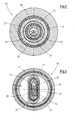
- This second supply channel 17 opens into a first outer channel section 18, which is likewise annular in shape and which surrounds the first inner channel section 16 concentrically with the axis 13, as shown in FIG. 2 reveals.
- the first outer channel section 18 is adjoined by an outer nozzle channel 19 which terminates in an outer nozzle 20.
- the outer nozzle channel 19 is formed in an outer nozzle tube 21, which ends with the outer nozzle 20 at a considerable distance in front of the forming section 5, as shown in FIG. 1.
- the first inner channel section 16 merges into a second inner channel section 22 which has an oval cross section.
- oval cross-section is understood to mean any cross-sectional shape which is not circular, has a large axis 23 and a small axis 24 perpendicular thereto, is symmetrical to the large axis 23 and the minor axis 24 and has no concave wall portions.
- the large axis 23 is in this case arranged vertically, as shown in FIGS. 3 to 7 can be seen.
- the second inner channel section 22 is formed in an also oval-shaped inner nozzle tube 25. As can be seen from FIGS.
- the inner nozzle tube 25 supports the outer nozzle tube 21 in the region of the large axis 23, that is to say in the vertical direction.
- the inner nozzle tube 25 has a cooling and calibrating means within the shaping section 5.
- Mandrel 26 attached.
- a protective tube 27 is arranged, are guided by the supply hoses 28, 29 for cooling water and 30, 31 for air at different pressures, which are guided to the cooling and calibration mandrel 26.
- the protective tube 27 also has an oval cross-section, as shown in FIGS. 3 to 6 can be removed.
- the outer nozzle channel 19 does not have the same width a in the area of the outer nozzle 20 as in the region of the first outer channel section 18 (see FIG. 2). Although it has a circular cross section; the width b in the upper and lower regions, that is to say in the upper and lower regions of the large axis 23, is greater than the width c in the lateral region, that is to say in the region of the small axis 24, as clearly shown in FIG. 4.
- the outer tube 11 has a wall thickness identical to the widths b and c, which is not constant over the circumference, but is significantly larger at the top and bottom than in the lateral areas, the transition being continuous .
- the second inner channel portion 22 and formed at the end of the inner nozzle tube 25 inner nozzle 32 over the entire circumference a constant width d, so that the wall thickness d of the inner tube 12 emerging from the inner tube 12 is substantially constant.
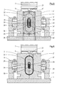
- 2 'oval annular mold recesses 33 are formed, open into the partial vacuum slots 34, 34', which are formed on part-vacuum channels 35, 35 'in the half-molds 2, 2'.
- These shape recesses 33 have an oval shape corresponding to the outer shape of a pipe to be produced.
- the outer tube 11 Due to the prevailing at the Formaus strictly adopted partial vacuum, ie negative pressure to atmospheric pressure, the outer tube 11 is sucked into the mold cavities 33 on entry into the mold section 5 and thus rests against the inner wall of the mold pairs.
- the outer tube 11 on exiting the outer nozzle 20 has an outer diameter f which is significantly smaller than the largest diameter g of the shaped recesses 33 in the direction of the large axis 23 and which is significantly larger than the smallest diameter h Due to these geometric conditions described, the outer nozzle 20 is also at a relatively large distance e in front of the closed molding section 5.
- the outer tube 11 is thus on entry into the leading in the production direction 6
- Form section 5 laterally in Direction of the small axis 24 compressed toward the central longitudinal axis with increasing the wall thickness and widened in the vertical direction in the direction of the major axis 23 while reducing the wall thickness, as Figs. 4 to 7 in conjunction with FIG. 1 can be removed. 1, this constriction is continuous, on the way from the outer nozzle 20 to the closed mold section 5.
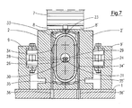
- the inner nozzle 32 is located in the initial region of the molding section 5, but already in the closed area where the outer tube 11 has already adopted the configuration of the Formaus Principle 33 corresponding oval wavy shape.
- the inner tube 12 already emerges with the cross-section from the inner nozzle 32 with which it is applied to the inner side of the outer tube and welded to the latter.
- the also oval cooling and calibration mandrel 26 supports the inner tube 12. This technique is well known, and for example in the EP 0 509 216 A2 (corresponding US 5,346,384 ) and described.
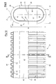
- the compound tube 37 produced in the manner described has an oval cross-section.
- this oval cross-section is bounded or formed by two parallel wall sections 38, 39 and two semicylindrical wall sections 40, 41 connecting them to form a closed cross-section.
- the tube 37 has the large axis 23 with a length g and a small axis 24 with a length h, wherein - as already mentioned - the lengths g and h are each based on the outer cross section of the tube 37.
- 1.5 ⁇ g / h ⁇ 5.0 For the ratio of the length g of the major axis 23 and the length h of the minor axis 24, 1.5 ⁇ g / h ⁇ 5.0. From these dimensional ratios also results in which considerable extent the outer tube 11 after exiting the outer nozzle 20 on the one hand constricted and on the other hand must be widened.
- the tube 37 also has in the same way an internal cross-section, which is bounded by a continuous smooth inner wall 42.
- This inner wall 42 is also formed by two parallel planar inner wall sections 43, 44 and two semicylindrical inner wall sections 45, 46 connecting them.
- the continuous smooth inner wall 42 defines a flow channel 47 for the transport of gas, in particular air, in air conditioning or in ventilation systems.
- the outer wall of the tube 37 is formed according to the described shape of the mold recesses 33 by corrugations 48. These have about trapezoidal cross-section. Neighboring corrugations 48 connecting foot sections 49 delimit troughs. In the area of the foot sections 49, the welding of outer tube 11 and inner tube 12 takes place.
Abstract
Description
Die Erfindung betrifft eine Vorrichtung zur Herstellung von Verbund-Rohren nach dem Oberbegriff des Anspruches 1.The invention relates to a device for producing composite pipes according to the preamble of
Eine derartige Vorrichtung ist beispielsweise aus der
Der Erfindung liegt daher die Aufgabe zugrunde, eine Vorrichtung der gattungsgemäßen Art so auszugestalten, dass auf ihr Verbund-Rohre mit ovalem Querschnitt hergestellt werden können.The invention is therefore based on the object, a device of the generic type in such a way that can be made on her compound pipes with an oval cross-section.
Diese Aufgabe wird erfindungsgemäß durch die Merkmale im Kennzeichnungsteil des Anspruches 1 gelöst. Durch die Ausgestaltung der Außendüse wird ein Außenschlauch extrudiert, dessen Durchmesser kleiner als die Länge der großen Achse, aber größer als die Länge der kleinen Achse des zu erzeugenden ovalen Verbund-Rohres ist. Die Außendüse ist in ausreichendem Abstand vor der bereits geschlossenen Formstrecke angeordnet, so dass der Außenschlauch auf dem Weg in die sich in Produktionsrichtung bewegende Formstrecke einerseits seitlich eingeschnürt und andererseits oben und unten aufgeweitet werden kann. Gleichzeitig wird die Gefahr ausgeschlossen, dass die Außendüse in Kollision mit Halbkokillen kommt, die sich der Formstrecke nähern und in diese eingeschwenkt werden. Der Innenschlauch dagegen wird bereits in einer Form extrudiert, die angenähert der endgültigen Form und Größe des zu erzeugenden Rohres entspricht.This object is achieved by the features in the characterizing part of
Durch die vorteilhafte Weiterbildung nach Anspruch 2 wird sichergestellt, dass der Außenschlauch nach der geschilderten Verformung auf dem Weg von der Außendüse zur Formstrecke über seinen Umfang eine zumindest angenähert identische Wanddicke erhält, was dann auch für die Außenwand des zu erzeugenden Rohres gilt.The advantageous development according to
Weitere Vorteile, Merkmale und Einzelheiten der Erfindung ergeben sich aus der nachfolgenden Beschreibung eines Ausführungsbeispiels anhand der Zeichnung. Es zeigt
- Fig. 1
- einen horizontalen Längsschnitt durch einen Teil einer erfindungsgemäßen Vorrichtung, und zwar durch einen Spritzkopf und den sich anschließenden Teil einer Formstrecke,
- Fig. 2
- einen Querschnitt durch den Spritzkopf gemäß der Schnittlinie II-II in Fig. 1,
- Fig. 3
- einen gegenüber Fig. 2 stromabwärts angelegten Querschnitt durch den Spritzkopf entsprechend der Schnittlinie III-III in Fig. 1,
- Fig. 4
- einen Querschnitt durch den Spritzkopf im Bereich der Außendüse entsprechend der Schnittlinie IV-IV in Fig. 1,
- Fig. 5
- einen Querschnitt durch die Formstrecke stromaufwärts der Innendüse entsprechend der Schnittlinie V-V in Fig. 1,
- Fig. 6
- einen Querschnitt durch die Formstrecke im Bereich der Innendüse entsprechend der Schnittlinie VI-VI in Fig. 1,
- Fig. 7
- einen Querschnitt durch die Formstrecke stromabwärts der Innendüse entsprechend der Schnittlinie VII-VII in Fig. 1,
- Fig. 8
- einen Teilausschnitt aus Fig. 1 im Bereich der Innendüse in gegenüber Fig. 1 stark vergrößertem Maßstab,
- Fig. 9
- ein auf der erfindungsgemäßen Vorrichtung hergestelltes Verbund-Rohr im Querschnitt entsprechend der Schnittlinie IX-IX in Fig. 10 und
- Fig. 10
- eine Längsansicht des Verbund-Rohres nach Fig. 9 in teilweise aufgebrochener Darstellung.
- Fig. 1
- 4 shows a horizontal longitudinal section through a part of a device according to the invention, namely by means of a spray head and the adjoining part of a molding section;
- Fig. 2
- a cross section through the spray head according to the section line II-II in Fig. 1,
- Fig. 3
- FIG. 2 shows a cross-section through the spray head taken downstream of FIG. 2 along section line III - III in FIG. 1, FIG.
- Fig. 4
- a cross section through the spray head in the region of the outer nozzle according to the section line IV-IV in Fig. 1,
- Fig. 5
- a cross section through the forming section upstream of the inner nozzle according to the section line VV in Fig. 1,
- Fig. 6
- a cross section through the molding section in the region of the inner nozzle according to the section line VI-VI in Fig. 1,
- Fig. 7
- a cross section through the forming section downstream of the inner nozzle according to the section line VII-VII in Fig. 1,
- Fig. 8
- 1 in the region of the inner nozzle in relation to FIG. 1 greatly enlarged scale,
- Fig. 9
- a composite pipe produced on the device according to the invention in cross section corresponding to the section line IX-IX in Fig. 10 and
- Fig. 10
- a longitudinal view of the composite tube of FIG. 9 in a partially broken view.
Die in Fig. 1 nur teilweise dargestellte Vorrichtung zur Herstellung von Verbund-Rohren aus thermoplastischem Kunststoff hat einen Grundaufbau, wie er beispielsweise aus der
Der Formstrecke 5 ist ein auch als Rohrkopf bezeichneter Spritzkopf 10 vorgeordnet, der dazu dient, zwei ineinander befindliche, also koextrudierte, warmplastische Kunststoffschläuche, nämlich einen Außenschlauch 11 und einen Innenschlauch 12 zu extrudieren. Der Spritzkopf 10 weist einen konzentrisch zu seiner Mittel-Längs-Achse 13 in ihn einmündenden ersten Zuführ-Kanal 14 auf, der an einen ersten Extruder angeschlossen ist. Dieser Zuführ-Kanal 14 wird an einem Führungskegel 15 aufgeweitet und führt danach zu einem ebenfalls konzentrisch zur Achse 13 angeordneten kreisringförmigen ersten Innenkanal-Abschnitt 16.The forming section 5 is preceded by a
Im - bezogen auf die Längsrichtung der Achse 13 - mittleren Bereich des ersten Innenkanal-Abschnitts 16 mündet seitlich in den Spritzkopf 10 ein zweiter Zufuhr-Kanal 17 ein, der an einen zweiten Extruder angeschlossen ist. Dieser zweite Zuführ-Kanal 17 mündet in einen ersten Außenkanal-Abschnitt 18, der ebenfalls kreisringförmig ausgebildet ist und der den ersten Innenkanal-Abschnitt 16 konzentrisch zur Achse 13 umgibt, wie Fig. 2 erkennen lässt.In - with respect to the longitudinal direction of the axis 13 - middle region of the first
An den ersten Außenkanal-Abschnitt 18 schließt sich ein Außendüsen-Kanal 19 an, der in einer Außendüse 20 endet. Der Außendüsen-Kanal 19 ist in einem Außendüsen-Rohr 21 ausgebildet, das mit der Außendüse 20 in deutlichem Abstand vor der Formstrecke 5 endet, wie Fig. 1 zeigt.The first
Am Übergang vom zumindest weitgehend massiven Spritzkopf 10 in das Außendüsen-Rohr 21 geht der erste Innenkanal-Abschnitt 16 in einen zweiten Innenkanal-Abschnitt 22 über, der ovalen Querschnitt aufweist. Unter ovalem Querschnitt wird hierbei jede Querschnittsform verstanden, die nicht kreisförmig ist, eine große Achse 23 und eine senkrecht hierauf stehende kleine Achse 24 aufweist, symmetrisch zur großen Achse 23 und zur kleinen Achse 24 ausgebildet ist und keine konkaven Wand-Abschnitte aufweist. Die große Achse 23 ist hierbei vertikal angeordnet, wie Fig. 3 bis 7 zu entnehmen ist. Der zweite Innenkanal-Abschnitt 22 ist in einem ebenfalls oval ausgebildeten Innendüsen-Rohr 25 ausgebildet. Wie aus Fig. 3 und 4 ersichtlich ist, stützt das Innendüsen-Rohr 25 im Bereich der großen Achse 23, also in der Vertikalen, das Außendüsen-Rohr 21. Am Innendüsen-Rohr 25 ist innerhalb der Formstrecke 5 ein Kühl- und Kalibrier-Dorn 26 angebracht. Innerhalb des Innendüsen-Rohres 25 ist ein Schutzrohr 27 angeordnet, durch das Versorgungs-Schläuche 28, 29 für Kühlwasser und 30, 31 für Luft mit unterschiedlichen Drücken geführt sind, die zum Kühl- und Kalibrier-Dorn 26 geführt werden. Im Innendüsen-Rohr 25 weist auch das Schutzrohr 27 ovalen Querschnitt auf, wie Fig. 3 bis 6 entnehmbar ist.At the transition from the at least largely
Wie Fig. 4 erkennen lässt, weist der Außendüsen-Kanal 19 im Bereich der Außendüse 20 nicht überall gleiche Weite a auf, wie im Bereich des ersten Außenkanal-Abschnitts 18 (siehe Fig. 2). Er weist zwar einen Kreisquerschnitt auf; die Weite b im oberen und unteren Bereich, also im oberen und unteren Bereich der großen Achse 23, ist größer als die Weite c im seitlichen Bereich, also im Bereich der kleinen Achse 24, wie aus Fig. 4 deutlich hervorgeht. Der Außenschlauch 11 weist also im Augenblick des Austritts aus der Außendüse 20 eine mit der Weite b und c identische Wanddicke auf, die über den Umfang nicht konstant ist, sondern oben und unten deutlich größer ist als in den seitlichen Bereichen, wobei der Übergang kontinuierlich ist. Demgegenüber weisen der zweite Innenkanal-Abschnitt 22 und die am Ende des Innendüsen-Rohres 25 ausgebildete Innendüse 32 über den gesamten Umfang eine konstante Weite d auf, so dass auch die Wanddicke d des aus der Innendüse 32 austretenden Innenschlauchs 12 im Wesentlichen konstant ist.As can be seen from FIG. 4, the
Aus der Außendüse 20 wird also ein Außenschlauch 11 extrudiert, der Kreisringform hat, allerdings mit deutlich unterschiedlichen Wanddicken b und c. Dieser Außenschlauch 11 wird in deutlichem Abstand e der Außendüse 20 von der Formstrecke 5 extrudiert, wo noch keine Kollision mit den sich seitlich nähernden Halbkokillen 2, 2' eintreten kann.From the
In den Halbkokillen 2, 2' sind ovale ringförmige Formausnehmungen 33 ausgebildet, in die Teil-Vakuum-Schlitze 34, 34' einmünden, die an Teil-Vakuum-Kanälen 35, 35' in den Halbkokillen 2, 2' ausgebildet sind. Diese Formausnehmungen 33 haben eine ovale Form, die der Außenform eines zu erzeugenden Rohres entspricht. Die Teil-Vakuum-Kanäle 35, 35' kommen auf der Formstrecke mit Teil-Vakuum-Anschlüssen 36, 36' in Überdeckung, die am Maschinentisch 1 ausgebildet sind und, wie es im Einzelnen aus der
Die Innendüse 32 befindet sich zwar im Anfangsbereich der Formstrecke 5, aber bereits in deren geschlossenem Bereich, wo der Außenschlauch 11 bereits seine der Ausgestaltung der Formausnehmungen 33 entsprechende ovale gewellte Form angenommen hat. Wie Fig. 6 entnehmbar ist, tritt der Innenschlauch 12 bereits mit dem Querschnitt aus der Innendüse 32 aus, mit dem er an die Innenseite des Außenschlauches angelegt und mit letzterem verschweißt wird. Der ebenfalls ovale Kühl- und Kalibrier-Dorn 26 stützt den Innenschlauch 12. Diese Technik ist allgemein bekannt, und beispielsweise im Einzelnen in der
Das in der geschilderten Weise hergestellte Verbundrohr 37 weist einen ovalen Querschnitt auf. Im konkreten Fall wird dieser ovale Querschnitt durch zwei zueinander parallele Wand-Abschnitte 38, 39 und zwei diese miteinander zu einem geschlossenen Querschnitt verbindende halbzylindrische Wand-Abschnitte 40, 41 begrenzt bzw. gebildet. Das Rohr 37 weist die große Achse 23 mit einer Länge g und eine kleine Achse 24 mit einer Länge h auf, wobei - wie bereits erwähnt - die Längen g und h jeweils auf den Außenquerschnitt des Rohres 37 bezogen sind. Für das Verhältnis der Länge g der großen Achse 23 und der Länge h der kleinen Achse 24 gilt: 1,5 ≤ g/h ≤ 5,0. Aus diesen Maßverhältnissen ergibt sich auch, in welchem erheblichen Maß der Außenschlauch 11 nach dem Austritt aus der Außendüse 20 einerseits eingeschnürt und andererseits aufgeweitet werden muss.The
Das Rohr 37 weist weiterhin in gleicher Weise einen Innen-Querschnitt auf, der durch eine durchgehend glatte Innenwand 42 begrenzt wird. Auch diese Innenwand 42 wird durch zwei zueinander parallele ebene Innenwand-Abschnitte 43, 44 und zwei diese verbindende halbzylindrische Innenwand-Abschnitte 45, 46 gebildet. Die durchgehend glatte Innenwand 42 begrenzt einen Strömungs-Kanal 47 für den Transport von Gas, insbesondere Luft, in Klima- bzw. in Lüftungs-Anlagen.The
Wie sich aus Fig. 9 und 10 ergibt, wird die Außenwand des Rohres 37 entsprechend der geschilderten Form der Formausnehmungen 33 durch Wellungen 48 gebildet. Diese weisen etwa Trapez-Querschnitt auf. Benachbarte Wellungen 48 verbindende Fuß-Abschnitte 49 begrenzen Wellentäler. Im Bereich der Fuß-Abschnitte 49 erfolgt die Verschweißung von Außenschlauch 11 und Innenschlauch 12.As is apparent from Fig. 9 and 10, the outer wall of the
Claims (5)
dass die Formausnehmungen (33) ovalen Querschnitt mit einer vertikal verlaufenden großen Achse (23) mit einer Länge g und mit einer horizontal verlaufenden kleinen Achse (24) mit einer Länge h aufweisen, dass die Innendüse (32) einen dem ovalen Querschnitt der Formausnehmungen (33) ähnlichen ovalen Querschnitt aufweist,
dass die Außendüse (20) etwa Kreisquerschnitt mit einem Durchmesser f aufweist, für den gilt: h < f < g und
dass sich die Außendüse (20) in einem Abstand e vor der Formstrecke (5) und außerhalb eines Kollisionsbereiches mit Halbkokillen (2, 2') befindet.Apparatus for producing composite pipes,
in that the mold recesses (33) have an oval cross-section with a vertically extending large axis (23) with a length g and with a horizontally extending small axis (24) with a length h such that the inner nozzle (32) has an oval cross-section of the mold recesses ( 33) has a similar oval cross section,
that the outer nozzle (20) has approximately circular cross-section with a diameter f, to which applies: H <f <g and
that the outer nozzle (20) is at a distance s before the molding path (5) and outside a collision area with the half shells (2, 2 ').
dass die Außendüse (20) eine sich über ihren Umfang stetig verändernde Weite aufweist, wobei für die Weite b im oberen und unteren Bereich im Vergleich zur Weite c in den seitlichen Bereichen gilt: c < b.Device according to claim 1, characterized in that
in that the outer nozzle (20) has a width that varies continuously over its circumference, wherein the following applies to the width b in the upper and lower regions in comparison to the width c in the lateral regions: c <b.
dass die Halbkokillen (2, 2') auf einem Maschinentisch (1) angeordnet sind.Device according to Claim 1 or 2, characterized
that the half shells (2, 2 ') on a machine table (1) are arranged.
dass auf der Formstrecke (5) im Maschinentisch (1) Teil-Vakuum-Anschlüsse (36, 36') angeordnet sind, die mit den Teil-VakuumKanälen (35, 35') in Überdeckung bringbar sind.Device according to claim 3, characterized in that
in that part-vacuum connections (36, 36 ') are arranged on the forming path (5) in the machine table (1) and can be brought into coincidence with the partial vacuum channels (35, 35').
dass für den Abstand e der Außendüse (20) von der Formstrecke (5) gilt: e ≥ 300 mm.Device according to one of claims 1 to 4, characterized
that applies to the distance e of the outer nozzle (20) of the molding path (5): e ≥ 300 mm.
Applications Claiming Priority (1)
| Application Number | Priority Date | Filing Date | Title |
|---|---|---|---|
| DE102006048512.2A DE102006048512B4 (en) | 2006-10-13 | 2006-10-13 | Apparatus for producing composite pipes |
Publications (2)
| Publication Number | Publication Date |
|---|---|
| EP1911565A2 true EP1911565A2 (en) | 2008-04-16 |
| EP1911565A3 EP1911565A3 (en) | 2010-03-17 |
Family
ID=38969400
Family Applications (1)
| Application Number | Title | Priority Date | Filing Date |
|---|---|---|---|
| EP07018037A Withdrawn EP1911565A3 (en) | 2006-10-13 | 2007-09-14 | Device for manufacturing composite pipes |
Country Status (5)
| Country | Link |
|---|---|
| US (1) | US7517210B1 (en) |
| EP (1) | EP1911565A3 (en) |
| JP (1) | JP2008094098A (en) |
| CA (1) | CA2605793A1 (en) |
| DE (1) | DE102006048512B4 (en) |
Cited By (2)
| Publication number | Priority date | Publication date | Assignee | Title |
|---|---|---|---|---|
| EP2261003A3 (en) * | 2009-06-11 | 2011-03-09 | Manfred Arno Alfred Lupke | Die tooling for extruding tubular product |
| EP2620683A1 (en) | 2012-01-24 | 2013-07-31 | Ralph Peter Hegler | Composite pipe for air conditioning and ventilation technology |
Families Citing this family (4)
| Publication number | Priority date | Publication date | Assignee | Title |
|---|---|---|---|---|
| EP2072988B1 (en) | 2007-12-19 | 2011-01-26 | Ralph-Peter Dr.-Ing. Hegler | Test method and device |
| US9744710B2 (en) * | 2012-01-13 | 2017-08-29 | U.S. Farathane Corporation | Assembly and process for creating an extruded pipe for use in a geothermal heat recovery operation |
| DE102012022409B3 (en) * | 2012-11-15 | 2013-05-29 | Heinz Gross | Hose head for use with trifunctional component for discharging molten tube for manufacturing of capillaries, tubes or pipes, has sleeve-shaped housing, in which melt is fed, where housing surrounds core |
| KR102096350B1 (en) * | 2019-09-02 | 2020-04-02 | 이경노 | Apparatus for forming flat inner wall spiral corrugated duct or smooth wall inner duct COD, and the duct formed thereby |
Citations (7)
| Publication number | Priority date | Publication date | Assignee | Title |
|---|---|---|---|---|
| GB1258181A (en) * | 1968-03-05 | 1971-12-22 | ||
| JPS59209122A (en) * | 1983-05-12 | 1984-11-27 | Japan Steel Works Ltd:The | Apparatus for controlling wall thickness of parison |
| US5320797A (en) * | 1992-03-31 | 1994-06-14 | Wilhelm Hegler | Method and apparatus for the continuous manufacture of a compound pipe with a pipe socket |
| DE19817109A1 (en) * | 1998-04-17 | 1999-10-21 | Kirchner Fraenk Rohr | Production of thermally stable oval corrugated tubing for vehicle cable looms |
| DE10032308A1 (en) * | 2000-07-04 | 2002-01-17 | Kirchner Fraenk Rohr | Corrugated tube arrangement e.g. for motor vehicle and aircraft manufacture, has corrugations troughs forming the free-conductor cross-section |
| EP1473136A1 (en) * | 2001-12-12 | 2004-11-03 | Sanoh Kogyo Kabushiki Kaisha | Method and device for manufacturing bellows tube |
| DE202005005056U1 (en) * | 2005-03-31 | 2005-06-02 | Hegler, Ralph Peter, Dr.-Ing. | Plastic pipe for air-conditioning systems has an elongate cross section with major and minor axes, a profiled outer surface and a smooth inner surface |
Family Cites Families (6)
| Publication number | Priority date | Publication date | Assignee | Title |
|---|---|---|---|---|
| AT325299B (en) * | 1967-02-27 | 1975-10-10 | Hegler Wilhelm | DEVICE FOR MANUFACTURING TUBES FROM THERMOPLASTIC PLASTIC |
| DE2637995C2 (en) * | 1976-08-24 | 1983-05-26 | Hegler, Wilhelm, 8730 Bad Kissingen | Process for the production of double-walled plastic pipes with an annularly corrugated outer wall and a smooth inner wall |
| DE3120480A1 (en) * | 1981-05-22 | 1982-12-09 | Hegler, Wilhelm, 8730 Bad Kissingen | DEVICE FOR PRODUCING PLASTIC PIPES WITH CROSS-GROOVE |
| DE4111228A1 (en) * | 1991-04-08 | 1992-10-15 | Wilhelm Hegler | DEVICE FOR PRODUCING PLASTIC TUBES |
| EP1204522A1 (en) | 1999-08-18 | 2002-05-15 | UNICOR GmbH Rahn Plastmaschinen | Device and method for producing corrugated pipes made of plastic |
| DE19947434B4 (en) * | 1999-08-19 | 2011-02-24 | Unicor Gmbh | Apparatus and method for producing plastic corrugated pipes |
-
2006
- 2006-10-13 DE DE102006048512.2A patent/DE102006048512B4/en not_active Expired - Fee Related
-
2007
- 2007-09-14 EP EP07018037A patent/EP1911565A3/en not_active Withdrawn
- 2007-10-04 CA CA002605793A patent/CA2605793A1/en not_active Abandoned
- 2007-10-10 JP JP2007264406A patent/JP2008094098A/en active Pending
- 2007-10-12 US US11/871,325 patent/US7517210B1/en not_active Expired - Fee Related
Patent Citations (8)
| Publication number | Priority date | Publication date | Assignee | Title |
|---|---|---|---|---|
| GB1258181A (en) * | 1968-03-05 | 1971-12-22 | ||
| JPS59209122A (en) * | 1983-05-12 | 1984-11-27 | Japan Steel Works Ltd:The | Apparatus for controlling wall thickness of parison |
| US5320797A (en) * | 1992-03-31 | 1994-06-14 | Wilhelm Hegler | Method and apparatus for the continuous manufacture of a compound pipe with a pipe socket |
| US5320797B1 (en) * | 1992-03-31 | 1997-04-08 | Wilhelm Hegler | Method and apparatus for the continuous manufacture of a compound pipe with a pipe socket |
| DE19817109A1 (en) * | 1998-04-17 | 1999-10-21 | Kirchner Fraenk Rohr | Production of thermally stable oval corrugated tubing for vehicle cable looms |
| DE10032308A1 (en) * | 2000-07-04 | 2002-01-17 | Kirchner Fraenk Rohr | Corrugated tube arrangement e.g. for motor vehicle and aircraft manufacture, has corrugations troughs forming the free-conductor cross-section |
| EP1473136A1 (en) * | 2001-12-12 | 2004-11-03 | Sanoh Kogyo Kabushiki Kaisha | Method and device for manufacturing bellows tube |
| DE202005005056U1 (en) * | 2005-03-31 | 2005-06-02 | Hegler, Ralph Peter, Dr.-Ing. | Plastic pipe for air-conditioning systems has an elongate cross section with major and minor axes, a profiled outer surface and a smooth inner surface |
Cited By (3)
| Publication number | Priority date | Publication date | Assignee | Title |
|---|---|---|---|---|
| EP2261003A3 (en) * | 2009-06-11 | 2011-03-09 | Manfred Arno Alfred Lupke | Die tooling for extruding tubular product |
| US8684719B2 (en) | 2009-06-11 | 2014-04-01 | Manfred A. A. Lupke | Die tooling for extruding tubular product |
| EP2620683A1 (en) | 2012-01-24 | 2013-07-31 | Ralph Peter Hegler | Composite pipe for air conditioning and ventilation technology |
Also Published As
| Publication number | Publication date |
|---|---|
| JP2008094098A (en) | 2008-04-24 |
| US20090098231A1 (en) | 2009-04-16 |
| US7517210B1 (en) | 2009-04-14 |
| DE102006048512B4 (en) | 2014-03-06 |
| DE102006048512A1 (en) | 2008-04-17 |
| EP1911565A3 (en) | 2010-03-17 |
| CA2605793A1 (en) | 2008-04-13 |
Similar Documents
| Publication | Publication Date | Title |
|---|---|---|
| EP0890770B1 (en) | Composite pipe with integrally formed socket and method of manufacturing the same | |
| EP0726134B1 (en) | Method and apparatus for producing a thermoplastic multi layer pipe, especially from polyolefin | |
| EP0995579B1 (en) | Method for continuous production of a composite pipe with socket and apparatus for carrying out the method | |
| DE4210482A1 (en) | Method and device for the continuous production of a composite pipe with a pipe socket | |
| EP1612030B1 (en) | Method for continuous manufacturing of a double walled corrugated pipe with a socket, the double walled corrugated pipe and the apparatus for performing the method | |
| EP0600214B1 (en) | Method and apparatus for the continuous manufacturing of a composite pipe having a substantially smooth external wall portion | |
| DE102006048512B4 (en) | Apparatus for producing composite pipes | |
| WO1998032202A1 (en) | Integral corrugated jacket pipe and method of producing the same | |
| EP2065159A1 (en) | Device for continuously manufacturing a connecting pipe with pipe sleeve | |
| EP2452803B1 (en) | Device for producing corrugated thermoplastic tubes | |
| EP2125329B1 (en) | Method and device for the continuous manufacture of a plastic composite pipe having a connecting sleeve | |
| WO2001058669A1 (en) | Device for producing profiled tubes consisting of synthetic material | |
| DE102006037556B4 (en) | Method and blow mold for producing interconnected plastic pipes | |
| EP2212093B1 (en) | Method for producing a double-walled thermoplastic corrugated pipe having a connecting sleeve | |
| EP2252449B1 (en) | Method and device for the continuous production of a composite pipe having a pipe bell and composite pipe | |
| EP2103412B1 (en) | Method for continuous manufacture of a connecting rod with rod fitting and device for executing the method | |
| EP2436504B1 (en) | Method for continuous manufacture of a connecting tube with rod fitting, connecting tube with rod fitting and device for executing the method and manufacturing the connecting tube | |
| DE2316835B2 (en) | Method and device for producing a composite pipe from thermoplastics | |
| DE202008018223U1 (en) | Apparatus for the continuous production of a composite pipe with pipe socket | |
| DE3426680C2 (en) | ||
| EP1239999B1 (en) | Method and apparatus for forming a pipe in several steps | |
| DE2119956C3 (en) | Process for the continuous production of a composite sheet made of thermoplastic material | |
| EP2192337A1 (en) | Flexible filling tube made of plastic | |
| DD152615A1 (en) | WASHING TUBE AND METHOD AND DEVICE FOR ITS MANUFACTURE | |
| EP1695810A2 (en) | Method and apparatus for manufacturing a corrugated pipe |
Legal Events
| Date | Code | Title | Description |
|---|---|---|---|
| PUAI | Public reference made under article 153(3) epc to a published international application that has entered the european phase |
Free format text: ORIGINAL CODE: 0009012 |
|
| AK | Designated contracting states |
Kind code of ref document: A2 Designated state(s): AT BE BG CH CY CZ DE DK EE ES FI FR GB GR HU IE IS IT LI LT LU LV MC MT NL PL PT RO SE SI SK TR |
|
| AX | Request for extension of the european patent |
Extension state: AL BA HR MK RS |
|
| PUAL | Search report despatched |
Free format text: ORIGINAL CODE: 0009013 |
|
| AK | Designated contracting states |
Kind code of ref document: A3 Designated state(s): AT BE BG CH CY CZ DE DK EE ES FI FR GB GR HU IE IS IT LI LT LU LV MC MT NL PL PT RO SE SI SK TR |
|
| AX | Request for extension of the european patent |
Extension state: AL BA HR MK RS |
|
| AKY | No designation fees paid | ||
| STAA | Information on the status of an ep patent application or granted ep patent |
Free format text: STATUS: THE APPLICATION IS DEEMED TO BE WITHDRAWN |
|
| 18D | Application deemed to be withdrawn |
Effective date: 20100918 |
|
| REG | Reference to a national code |
Ref country code: DE Ref legal event code: R108 Effective date: 20110215 Ref country code: DE Ref legal event code: 8566 |