EP1910003B1 - Universalmaschine zur weichbearbeitung von kegelrädern und entsprechendes verfahren - Google Patents
Universalmaschine zur weichbearbeitung von kegelrädern und entsprechendes verfahren Download PDFInfo
- Publication number
- EP1910003B1 EP1910003B1 EP05769809A EP05769809A EP1910003B1 EP 1910003 B1 EP1910003 B1 EP 1910003B1 EP 05769809 A EP05769809 A EP 05769809A EP 05769809 A EP05769809 A EP 05769809A EP 1910003 B1 EP1910003 B1 EP 1910003B1
- Authority
- EP
- European Patent Office
- Prior art keywords
- tool
- cutter head
- lathe
- workpiece blank
- axis
- Prior art date
- Legal status (The legal status is an assumption and is not a legal conclusion. Google has not performed a legal analysis and makes no representation as to the accuracy of the status listed.)
- Not-in-force
Links
- 238000003754 machining Methods 0.000 title claims abstract description 22
- 238000000034 method Methods 0.000 title claims abstract description 13
- 238000007514 turning Methods 0.000 claims abstract description 13
- 239000002826 coolant Substances 0.000 claims 1
- 239000000314 lubricant Substances 0.000 claims 1
- 238000003801 milling Methods 0.000 abstract description 14
- 238000004519 manufacturing process Methods 0.000 abstract description 7
- 238000006073 displacement reaction Methods 0.000 description 3
- 239000000919 ceramic Substances 0.000 description 2
- 238000005553 drilling Methods 0.000 description 2
- 239000002184 metal Substances 0.000 description 2
- 229910000831 Steel Inorganic materials 0.000 description 1
- 238000013459 approach Methods 0.000 description 1
- 239000011195 cermet Substances 0.000 description 1
- 239000011248 coating agent Substances 0.000 description 1
- 238000000576 coating method Methods 0.000 description 1
- 230000001419 dependent effect Effects 0.000 description 1
- 238000009837 dry grinding Methods 0.000 description 1
- 238000005516 engineering process Methods 0.000 description 1
- 238000010438 heat treatment Methods 0.000 description 1
- 230000010354 integration Effects 0.000 description 1
- 238000005461 lubrication Methods 0.000 description 1
- 239000000463 material Substances 0.000 description 1
- 239000010959 steel Substances 0.000 description 1
- 230000009466 transformation Effects 0.000 description 1
Images

Classifications
-
- B—PERFORMING OPERATIONS; TRANSPORTING
- B23—MACHINE TOOLS; METAL-WORKING NOT OTHERWISE PROVIDED FOR
- B23P—METAL-WORKING NOT OTHERWISE PROVIDED FOR; COMBINED OPERATIONS; UNIVERSAL MACHINE TOOLS
- B23P23/00—Machines or arrangements of machines for performing specified combinations of different metal-working operations not covered by a single other subclass
- B23P23/02—Machine tools for performing different machining operations
-
- B—PERFORMING OPERATIONS; TRANSPORTING
- B23—MACHINE TOOLS; METAL-WORKING NOT OTHERWISE PROVIDED FOR
- B23F—MAKING GEARS OR TOOTHED RACKS
- B23F21/00—Tools specially adapted for use in machines for manufacturing gear teeth
- B23F21/12—Milling tools
- B23F21/16—Hobs
- B23F21/163—Hobs with inserted cutting elements
- B23F21/166—Hobs with inserted cutting elements in exchangeable arrangement
-
- B—PERFORMING OPERATIONS; TRANSPORTING
- B23—MACHINE TOOLS; METAL-WORKING NOT OTHERWISE PROVIDED FOR
- B23B—TURNING; BORING
- B23B3/00—General-purpose turning-machines or devices, e.g. centre lathes with feed rod and lead screw; Sets of turning-machines
- B23B3/16—Turret lathes for turning individually-chucked workpieces
- B23B3/161—Turret lathes for turning individually-chucked workpieces lathe with one toolslide carrying one turret head
- B23B3/162—Arrangements for performing other machining operations, e.g. milling, drilling
-
- B—PERFORMING OPERATIONS; TRANSPORTING
- B23—MACHINE TOOLS; METAL-WORKING NOT OTHERWISE PROVIDED FOR
- B23B—TURNING; BORING
- B23B3/00—General-purpose turning-machines or devices, e.g. centre lathes with feed rod and lead screw; Sets of turning-machines
- B23B3/22—Turning-machines or devices with rotary tool heads
-
- B—PERFORMING OPERATIONS; TRANSPORTING
- B23—MACHINE TOOLS; METAL-WORKING NOT OTHERWISE PROVIDED FOR
- B23F—MAKING GEARS OR TOOTHED RACKS
- B23F21/00—Tools specially adapted for use in machines for manufacturing gear teeth
- B23F21/12—Milling tools
- B23F21/22—Face-mills for longitudinally-curved gear teeth
- B23F21/223—Face-mills for longitudinally-curved gear teeth with inserted cutting elements
- B23F21/226—Face-mills for longitudinally-curved gear teeth with inserted cutting elements in exchangeable arrangement
-
- B—PERFORMING OPERATIONS; TRANSPORTING
- B23—MACHINE TOOLS; METAL-WORKING NOT OTHERWISE PROVIDED FOR
- B23F—MAKING GEARS OR TOOTHED RACKS
- B23F5/00—Making straight gear teeth involving moving a tool relatively to a workpiece with a rolling-off or an enveloping motion with respect to the gear teeth to be made
- B23F5/20—Making straight gear teeth involving moving a tool relatively to a workpiece with a rolling-off or an enveloping motion with respect to the gear teeth to be made by milling
- B23F5/205—Making straight gear teeth involving moving a tool relatively to a workpiece with a rolling-off or an enveloping motion with respect to the gear teeth to be made by milling with plural tools
-
- B—PERFORMING OPERATIONS; TRANSPORTING
- B23—MACHINE TOOLS; METAL-WORKING NOT OTHERWISE PROVIDED FOR
- B23F—MAKING GEARS OR TOOTHED RACKS
- B23F9/00—Making gears having teeth curved in their longitudinal direction
- B23F9/08—Making gears having teeth curved in their longitudinal direction by milling, e.g. with helicoidal hob
- B23F9/10—Making gears having teeth curved in their longitudinal direction by milling, e.g. with helicoidal hob with a face-mill
-
- B—PERFORMING OPERATIONS; TRANSPORTING
- B23—MACHINE TOOLS; METAL-WORKING NOT OTHERWISE PROVIDED FOR
- B23Q—DETAILS, COMPONENTS, OR ACCESSORIES FOR MACHINE TOOLS, e.g. ARRANGEMENTS FOR COPYING OR CONTROLLING; MACHINE TOOLS IN GENERAL CHARACTERISED BY THE CONSTRUCTION OF PARTICULAR DETAILS OR COMPONENTS; COMBINATIONS OR ASSOCIATIONS OF METAL-WORKING MACHINES, NOT DIRECTED TO A PARTICULAR RESULT
- B23Q39/00—Metal-working machines incorporating a plurality of sub-assemblies, each capable of performing a metal-working operation
- B23Q39/02—Metal-working machines incorporating a plurality of sub-assemblies, each capable of performing a metal-working operation the sub-assemblies being capable of being brought to act at a single operating station
- B23Q39/021—Metal-working machines incorporating a plurality of sub-assemblies, each capable of performing a metal-working operation the sub-assemblies being capable of being brought to act at a single operating station with a plurality of toolheads per workholder, whereby the toolhead is a main spindle, a multispindle, a revolver or the like
- B23Q39/022—Metal-working machines incorporating a plurality of sub-assemblies, each capable of performing a metal-working operation the sub-assemblies being capable of being brought to act at a single operating station with a plurality of toolheads per workholder, whereby the toolhead is a main spindle, a multispindle, a revolver or the like with same working direction of toolheads on same workholder
- B23Q39/024—Metal-working machines incorporating a plurality of sub-assemblies, each capable of performing a metal-working operation the sub-assemblies being capable of being brought to act at a single operating station with a plurality of toolheads per workholder, whereby the toolhead is a main spindle, a multispindle, a revolver or the like with same working direction of toolheads on same workholder consecutive working of toolheads
-
- Y—GENERAL TAGGING OF NEW TECHNOLOGICAL DEVELOPMENTS; GENERAL TAGGING OF CROSS-SECTIONAL TECHNOLOGIES SPANNING OVER SEVERAL SECTIONS OF THE IPC; TECHNICAL SUBJECTS COVERED BY FORMER USPC CROSS-REFERENCE ART COLLECTIONS [XRACs] AND DIGESTS
- Y10—TECHNICAL SUBJECTS COVERED BY FORMER USPC
- Y10T—TECHNICAL SUBJECTS COVERED BY FORMER US CLASSIFICATION
- Y10T29/00—Metal working
- Y10T29/51—Plural diverse manufacturing apparatus including means for metal shaping or assembling
- Y10T29/5104—Type of machine
- Y10T29/5109—Lathe
- Y10T29/5112—Convertible
-
- Y—GENERAL TAGGING OF NEW TECHNOLOGICAL DEVELOPMENTS; GENERAL TAGGING OF CROSS-SECTIONAL TECHNOLOGIES SPANNING OVER SEVERAL SECTIONS OF THE IPC; TECHNICAL SUBJECTS COVERED BY FORMER USPC CROSS-REFERENCE ART COLLECTIONS [XRACs] AND DIGESTS
- Y10—TECHNICAL SUBJECTS COVERED BY FORMER USPC
- Y10T—TECHNICAL SUBJECTS COVERED BY FORMER US CLASSIFICATION
- Y10T29/00—Metal working
- Y10T29/51—Plural diverse manufacturing apparatus including means for metal shaping or assembling
- Y10T29/5104—Type of machine
- Y10T29/5109—Lathe
- Y10T29/5114—Lathe and tool
-
- Y—GENERAL TAGGING OF NEW TECHNOLOGICAL DEVELOPMENTS; GENERAL TAGGING OF CROSS-SECTIONAL TECHNOLOGIES SPANNING OVER SEVERAL SECTIONS OF THE IPC; TECHNICAL SUBJECTS COVERED BY FORMER USPC CROSS-REFERENCE ART COLLECTIONS [XRACs] AND DIGESTS
- Y10—TECHNICAL SUBJECTS COVERED BY FORMER USPC
- Y10T—TECHNICAL SUBJECTS COVERED BY FORMER US CLASSIFICATION
- Y10T29/00—Metal working
- Y10T29/51—Plural diverse manufacturing apparatus including means for metal shaping or assembling
- Y10T29/5152—Plural diverse manufacturing apparatus including means for metal shaping or assembling with turret mechanism
- Y10T29/5153—Multiple turret
-
- Y—GENERAL TAGGING OF NEW TECHNOLOGICAL DEVELOPMENTS; GENERAL TAGGING OF CROSS-SECTIONAL TECHNOLOGIES SPANNING OVER SEVERAL SECTIONS OF THE IPC; TECHNICAL SUBJECTS COVERED BY FORMER USPC CROSS-REFERENCE ART COLLECTIONS [XRACs] AND DIGESTS
- Y10—TECHNICAL SUBJECTS COVERED BY FORMER USPC
- Y10T—TECHNICAL SUBJECTS COVERED BY FORMER US CLASSIFICATION
- Y10T29/00—Metal working
- Y10T29/51—Plural diverse manufacturing apparatus including means for metal shaping or assembling
- Y10T29/5176—Plural diverse manufacturing apparatus including means for metal shaping or assembling including machining means
-
- Y—GENERAL TAGGING OF NEW TECHNOLOGICAL DEVELOPMENTS; GENERAL TAGGING OF CROSS-SECTIONAL TECHNOLOGIES SPANNING OVER SEVERAL SECTIONS OF THE IPC; TECHNICAL SUBJECTS COVERED BY FORMER USPC CROSS-REFERENCE ART COLLECTIONS [XRACs] AND DIGESTS
- Y10—TECHNICAL SUBJECTS COVERED BY FORMER USPC
- Y10T—TECHNICAL SUBJECTS COVERED BY FORMER US CLASSIFICATION
- Y10T409/00—Gear cutting, milling, or planing
- Y10T409/10—Gear cutting
- Y10T409/101431—Gear tooth shape generating
- Y10T409/103816—Milling with radial faced tool
- Y10T409/104134—Adapted to cut bevel gear
-
- Y—GENERAL TAGGING OF NEW TECHNOLOGICAL DEVELOPMENTS; GENERAL TAGGING OF CROSS-SECTIONAL TECHNOLOGIES SPANNING OVER SEVERAL SECTIONS OF THE IPC; TECHNICAL SUBJECTS COVERED BY FORMER USPC CROSS-REFERENCE ART COLLECTIONS [XRACs] AND DIGESTS
- Y10—TECHNICAL SUBJECTS COVERED BY FORMER USPC
- Y10T—TECHNICAL SUBJECTS COVERED BY FORMER US CLASSIFICATION
- Y10T409/00—Gear cutting, milling, or planing
- Y10T409/10—Gear cutting
- Y10T409/101431—Gear tooth shape generating
- Y10T409/105883—Using rotary cutter
- Y10T409/106201—Plural rotary cutters
-
- Y—GENERAL TAGGING OF NEW TECHNOLOGICAL DEVELOPMENTS; GENERAL TAGGING OF CROSS-SECTIONAL TECHNOLOGIES SPANNING OVER SEVERAL SECTIONS OF THE IPC; TECHNICAL SUBJECTS COVERED BY FORMER USPC CROSS-REFERENCE ART COLLECTIONS [XRACs] AND DIGESTS
- Y10—TECHNICAL SUBJECTS COVERED BY FORMER USPC
- Y10T—TECHNICAL SUBJECTS COVERED BY FORMER US CLASSIFICATION
- Y10T409/00—Gear cutting, milling, or planing
- Y10T409/10—Gear cutting
- Y10T409/107791—Using rotary cutter
- Y10T409/108109—End mill
- Y10T409/108268—Radially faced
-
- Y—GENERAL TAGGING OF NEW TECHNOLOGICAL DEVELOPMENTS; GENERAL TAGGING OF CROSS-SECTIONAL TECHNOLOGIES SPANNING OVER SEVERAL SECTIONS OF THE IPC; TECHNICAL SUBJECTS COVERED BY FORMER USPC CROSS-REFERENCE ART COLLECTIONS [XRACs] AND DIGESTS
- Y10—TECHNICAL SUBJECTS COVERED BY FORMER USPC
- Y10T—TECHNICAL SUBJECTS COVERED BY FORMER US CLASSIFICATION
- Y10T409/00—Gear cutting, milling, or planing
- Y10T409/10—Gear cutting
- Y10T409/107791—Using rotary cutter
- Y10T409/108745—Cutting action along work axis
- Y10T409/108904—Cutting action intersecting work axis
-
- Y—GENERAL TAGGING OF NEW TECHNOLOGICAL DEVELOPMENTS; GENERAL TAGGING OF CROSS-SECTIONAL TECHNOLOGIES SPANNING OVER SEVERAL SECTIONS OF THE IPC; TECHNICAL SUBJECTS COVERED BY FORMER USPC CROSS-REFERENCE ART COLLECTIONS [XRACs] AND DIGESTS
- Y10—TECHNICAL SUBJECTS COVERED BY FORMER USPC
- Y10T—TECHNICAL SUBJECTS COVERED BY FORMER US CLASSIFICATION
- Y10T409/00—Gear cutting, milling, or planing
- Y10T409/10—Gear cutting
- Y10T409/109699—Gear cutting with work clamping
-
- Y—GENERAL TAGGING OF NEW TECHNOLOGICAL DEVELOPMENTS; GENERAL TAGGING OF CROSS-SECTIONAL TECHNOLOGIES SPANNING OVER SEVERAL SECTIONS OF THE IPC; TECHNICAL SUBJECTS COVERED BY FORMER USPC CROSS-REFERENCE ART COLLECTIONS [XRACs] AND DIGESTS
- Y10—TECHNICAL SUBJECTS COVERED BY FORMER USPC
- Y10T—TECHNICAL SUBJECTS COVERED BY FORMER US CLASSIFICATION
- Y10T82/00—Turning
- Y10T82/25—Lathe
- Y10T82/2502—Lathe with program control
-
- Y—GENERAL TAGGING OF NEW TECHNOLOGICAL DEVELOPMENTS; GENERAL TAGGING OF CROSS-SECTIONAL TECHNOLOGIES SPANNING OVER SEVERAL SECTIONS OF THE IPC; TECHNICAL SUBJECTS COVERED BY FORMER USPC CROSS-REFERENCE ART COLLECTIONS [XRACs] AND DIGESTS
- Y10—TECHNICAL SUBJECTS COVERED BY FORMER USPC
- Y10T—TECHNICAL SUBJECTS COVERED BY FORMER US CLASSIFICATION
- Y10T82/00—Turning
- Y10T82/25—Lathe
- Y10T82/2508—Lathe with tool turret
Definitions
- the present invention relates to an apparatus and a method for the soft machining of bevel gears, in particular for dry machining.
- the invention also relates to a corresponding method.
- EP-A-0 832 716 discloses a universal machine which discloses a pivotable cutter head for machining teeth on a bevel gear blank.
- the pivoting of the cutter head is done about an axis which is perpendicular to the axis of the work spindle.
- it is useful for machining bevel gears or even arcuate gears in spur gears, but not in bevel gears.
- the invention has for its object to simplify the production of bevel gears.
- Another object of the invention is to provide a corresponding device that is inexpensive.
- the inventive device is relatively inexpensive and can therefore be used in situations where complex and therefore often expensive processing machines do not pay.
- the inventive method is designed especially for the machining of tooth flanks before a hardening process, ie in the soft state. Accordingly, the tools to be used are to be selected.
- this term also includes ring gears and bevel pinions. Also included are bevel gears without axial offset and bevel gears with axial offset, so-called hypoid gears.
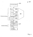
- Fig. 1 shows a schematic representation of an exemplary process flow 10.
- the invention can be used advantageously in the context shown. It is, as mentioned, an example of the processing of a bevel gear.
- a workpiece blank box 101
- the following soft machining steps are carried out in the example shown. For example, it can drill (central) through drilling (Box 102) are generated. Then, with a turning tool, the workpiece blank can be machined by turning (box 103).
- These steps are referred to herein as preforming or pre-machining.
- preforming As part of preforming, other steps or alternate steps may be performed.
- the workpiece is referred to as a blank wheel.
- gearing preferably (dry) bevel gear milling (box 104) is used to produce teeth on the wheel blank.
- deburring follows (box 105).
- the steps 102, 103 and 104 or the steps 102 - 105 can be carried out according to the invention in a device 20 according to the invention.
- the method according to the invention for soft machining of bevel wheels comprises the steps according to claim 8.
- the gearing is now performed. This happens as follows.
- a second soft machining of the wheel blank is carried out with a cutter head 27, which is clamped on a tool receiver 26.
- the aim of this second soft machining is to generate a toothing on the wheel blank.
- the second soft machining comprises (dry) bevel wheel milling of the wheel blank by means of a cutter head 27.
- the multifunctional tool holder 25 is located on the tool base 24, and the cutter head 27 on the tool receiver 26 in a horizontal plane to the main axis B1 of the lathe 22.
- the tool base 24 is located the one and the tool holder 26 on the other side next to the axis B1.
- all processing steps can be carried out dry.
- the device 20 must be designed and designed accordingly, especially to be able to dissipate the hot chips.
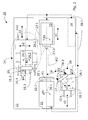
- the inventive device 20 is in the Fig. 2 shown.
- the apparatus 20 is specifically designed for use in soft machining of bevel gears and includes a CNC controlled lathe 22 having a work spindle 22.1 for receiving the workpiece blank K1.
- the device 20 has a tool base 24 with various tools 25.1 - 25.3 and a tool holder 26 for receiving a gear tool (for example, a milling head 27) for toothing a wheel blank.
- a counter-holder 23 may be provided.
- the device 20 is a horizontally operating processing station on the basis of a lathe, in which the tool holder 26 with the cutter head 27 during toothing is arranged laterally to the work spindle 22.1 with the wheel blank. (It is also possible to use a vertical version with a similar overall design.)
- the lathe 22, together with the tool receiver 26, forms a functional unit in which the workpiece blank K1 undergoes a first soft machining in order to be intermeshed by the cutter head 27 after the first soft machining as a wheel blank.
- the device 20 has a CNC controller 28 which is in Fig. 2 is indicated.
- the CNC controller 28 is at least connected to the following system parts 22, 24, 25, 26 of the device 20 control technology, which in Fig. 2 indicated by the arrows 34.1.
- This link can be made via a bus or via a cable connection. It is also conceivable to use another type of interface, for example a wireless connection, in order to link the CNC controller 28 to the individual system parts 22, 24, 25, 26.
- the lathe 22 has a main rotation axis B1.
- the work spindle 22 can rotate about this axis B1, as indicated by the double arrow 29.1.
- the counter-holder 23 is seated coaxially to the work spindle 22.1 on a carriage 23.1 and can be displaced in the longitudinal direction to the main axis of rotation B1, as shown by the arrow x1.
- the tool base 24 has a rotation axis B2.
- the tool holder 25 can be rotated about this axis B2, as indicated by the double arrow 29.2.
- the tool base 24 is seated on a carriage 24.1, 24.2 and can thus be moved including tools 25.1, 25.2, 25.3 in the axes x2, y2.
- the cutter head 27 can rotate about the axis B3, as indicated by the double arrow 29.3. Furthermore, the tool holder 26 sits on a carriage 26.1, 26.2 and can be moved in different directions, as shown by the arrows x3, y3.
- the work spindle 22.1 together with workpiece blank K1 and / or wheel blank can not be moved translationally.
- a displacement parallel to the axis x1 is not absolutely necessary, since the tool 25.1, 25.2, 25.3 and the cutter head 27 can be delivered, in which the tool base 24 or the tool holder 26 are moved parallel to the axis x1.
- a shift of the lathe 22 in the plane perpendicular to the axis x1 is also not mandatory, since the tool base 24 and the tool holder 26 can be moved in the y-direction y2, y3.
- the work spindle 22.1 can still be arranged on a carriage to gain more degrees of freedom.
- the different axes are numerically controlled axes.
- the individual movements can be numerically controlled by the CNC controller 28.
- the controller 28 is designed so that all axes are controlled numerically controlled. It is important that every single movement is coordinated. This coordination is performed by the CNC controller 28.
- the device 20 according to the invention is special in this respect and thus stands out from other known approaches than the individual processing stations 24, 26 are arranged horizontally.
- the position of the various numerically controlled axes has been chosen so that there is as much room for maneuvering the workpiece / wheel blank as possible. Particularly preferred is the following arrangement of the individual axes.
- Tool base 24 Axis x2 is parallel to axis x1, whereby the two axes can be offset from each other by performing a relative movement parallel to the y2 direction. This can be worked out for example with a drill 25.3 a central bore in the workpiece blank K1.
- the tool base 24 together with slide 24.1, 24.2 is arranged next to the work spindle 22.1 and it is possible to change the relative distance from one another in which relative displacements are made parallel to x2 and / or y2.
- the two axes x1, x2 can also be offset from one another in the depth (perpendicular to the plane of the drawing).
- the carriage 24.1, 24.2 can be moved parallel to an optional z2 axis.
- Tool holder 26 with cutter head 27 axis x3 preferably runs parallel to the axis x1.
- the tool holder 26 together with carriage 26.1, 26.2 is also arranged horizontally to the work spindle 22.1 and the relative distance to each other can be changed by making a relative displacement parallel to the x3, y3 axes.
- the two axes x1, x3 can be offset from one another laterally (in the plane of the drawing).
- the carriage 26.1 can be moved parallel to the y3 axis.
- the two axes x1, x3 can also be offset from one another in the depth (perpendicular to the plane of the drawing).
- the carriage 26.1, 26.2 can be moved parallel to an optional z3 axis.
- an angle W between the two axes B1 and B3 can be set and changed, as in FIG Fig. 2 shown where the angle is about 40 °. It is preferably possible Winkelver auskeit in the range of W1 to W2. W is usually not set to a fixed value but is changed during milling.
- the work spindle 22.1 for receiving the workpiece blank K1 on a clamping or gripping means in order to clamp the workpiece blank / wheel blank can.
- the clamping or gripping means are designed for automatic clamping.
- the tool base 24 of the device 20 is preferably equipped with a tool turret 25.2, which can accommodate a plurality of tools. Particularly preferred is an embodiment in which at least one of the tools, which are located in the multifunctional tool head 25 or in the tool turret 25.2, can be driven individually.
- the tool turret 25.2 per se can be rotated about an axis B4, as indicated by the double arrow 25.4
- the tool base 24 can be used for turning, scoring, drilling, etc.
- the multifunctional tool holder 25 has several tool holders in the illustrated embodiment. In the example shown there are three tools 25.1 - 25.3.
- the multifunctional tool holder 25 is preferably designed so that at least one of the tool holder is designed as a spindle head in order to be able to drive the corresponding tool individually.
- the tool 25.3 may, for example, be a drill or a milling head which can be set in rotation about its longitudinal axis.
- the tools 25. 1 and 25. 2 can be, for example, tool turrets, turning tools or deburring heads, which are each firmly clamped in a tool holder of the multifunctional tool holder 25.
- the device 20 can be modified and adapted to the basic conditions.
- a device 20 which is characterized in that the device 20 comprises a CNC control 28 which is designed so that the lathe 22, the tool base 24 and the tool holder 25 as a functional unit together with the tool holder 26 is operable.
- the advantage of the fact that there is only one CNC controller, for example located in the lathe 21, or that is designed to operate with the lathe 21, is seen in the fact that thereby the device 20 can be realized more cheaply.
- This cost savings is mainly due to the fact that Kegelradfräsen with the cutter head 27 does not need its own CNC controller 28.
- the linking of the axes is much less expensive and the coordination of the individual movements on the device 20 is easier.
- FIG. 3 Another embodiment is in Fig. 3 shown. This embodiment is based on the previously described principle of the invention. Therefore, as far as appropriate, the same reference numerals in the Fig. 3 used.
- Fig. 3 shows a device 30 in which the multifunctional tool holder 34 also serves as a tool holder 36 for a cutter head 27 at the same time.
- the carriage 24.2 can be rotated about a vertical axis B5, as indicated by the double arrow 29.3. This allows the cutter head 27 in the in Fig. 3 schematically indicated position 27 'are rotated. Bar knife on the cutter head 27 can then make the milling of the wheel blank K1. In this milling, both the cutter head 27 is rotated about its axis B3 and the wheel blank about the axis B2. In the turning, which precedes, for example, the milling, one of the other tools 25.1 or 25.3 can be used.
- the control is carried out by a CNC control 38, which is designed differently because of the slightly different arrangement of the axes and integration of the cutter head 27 in the tool holder 34 as the controller 28 in Fig. 2 ,
- the tool holder 26, 36 or 46 is designed for dry milling or milling with minimum lubrication (MQL) of bevel gears.
- tools made of high-performance steel, of hard metal, of ceramic, or of cermet (combination of metal and ceramic), each with a suitable hard material coating are used for gear processing by bevel gear milling, depending on the hardness of the workpiece.
Description
- Die vorliegende Erfindung betrifft eine Vorrichtung und ein Verfahren für die Weichbearbeitung von Kegelrädern, insbesondere zum Trockenbearbeiten. Die Erfindung betrifft auch ein entsprechendes Verfahren.
- Es gibt verschiedenste Maschinen, die bei der Fertigung von Kegelrädern und ähnlichen Zahnrädern zum Einsatz kommen. Seit einiger Zeit besteht der Wunsch die Fertigung zu automatisieren. Eine Lösung, die sich bisher aber nur bedingt hat durchsetzen können, ist ein Bearbeitungszentrum, das so ausgelegt ist, dass eine ganze Anzahl von Fertigungsschritten auf ein und derselben Maschine ausgeführt werden können. Solche Maschinen sind nicht nur sehr komplex und daher teuer, sondern erfordern auch einen relativ großen Aufwand beim vorbereitenden Einrichten (Rüstzeit). Auf der anderen Seite sind solche Maschinen, die im Hinblick auf die hohe Flexibilität entwickelt wurden, eher dazu geeignet Einzelanfertigungen oder Kleinstserien zu produzieren.
- In dem Europäischen Patent
EP 0 832 716 B1 ist eine kompakte Maschine gezeigt und beschrieben, die für das Drehen und Wälzfräsen eines Werkstücks ausgelegt ist, wobei dieses Werkstück nicht umgespannt oder transferiert werden muss. Mit anderen Worten ausgedrückt sitzt das Werkstück nach dem Aufspannen an einer Hauptspindel und wird dort mit verschiedenen Werkzeugen bearbeitet. Es wird als ein Nachteil dieser Maschine angesehen, dass sie aufgrund der Anordnung der verschiedenen Elemente nicht dazu ausgelegt ist eine Trockenbearbeitung auszuführen, da bei der Trockenbearbeitung die Abfuhr der heißen Späne von besonderer Bedeutung ist. Außerdem ist durch die seitliche Anordnung der beiden Schlitten mit den Werkzeugen in Bezug auf das Werkstück der Bewegungsspielraum eingeschränkt. - Die Veröffentlichungsschrift
EP-A-0 832 716 offenbart eine Universalmaschine, die einen schwenkbaren Messerkopf für die Bearbeitung von Zähnen an einem Kegelzahnrad-Rohling offenbart. Die Schwenkbarkeit des Messerkopfes geschieht um eine Achse, die senkrecht zu der Achse der Arbeitsspindel steht. Somit ist sie nützlich für die Bearbeitung von schrägen Verzahnungen oder auch bogenförmigen Verzahnungen bei Stirnzahnrädern, nicht jedoch bei Kegelzahnrädern. - Der Erfindung liegt die Aufgabe zugrunde, die Fertigung von Kegelrädern zu vereinfachen.
- Eine weitere Aufgabe der Erfindung besteht darin eine entsprechende Vorrichtung bereit zu stellen, die kostengünstig ist.
- Diese Aufgaben werden gemäss der Erfindung durch die Merkmale des Anspruchs 1 und durch die Merkmale des Anspruchs 8 gelöst. Weitere vorteilhafte Ausgestaltungen ergeben sich aus den Unteransprüchen.
- Die erfindungsgemässe Vorrichtung ist relativ kostengünstig und kann daher in Situationen zum Einsatz kommen, wo komplexe und daher oft auch teure Bearbeitungsmaschinen sich nicht rechnen. Das erfindungsgemässe Verfahren ist speziell für die Bearbeitung von Zahnflanken vor einem Härteprozess, also im weichen Zustand, ausgelegt. Entsprechend sind die Werkzeuge auszuwählen, die zum Einsatz kommen.
- Ausführungsbeispiele der Erfindung werden im Folgenden unter Bezugnahme auf die Zeichnungen näher beschrieben. Es zeigen:
- FIG. 1
- eine schematische Darstellung der verschiedenen Bearbeitungsschritte beim Herstellen von Kegelrädern;
- FIG. 2
- eine schematische Darstellung einer ersten Vorrichtung zur Verwendung bei der Weichbearbeitung von Kegelrädern, gemäss Erfindung;
- FIG. 3
- eine schematische Darstellung einer zweiten Vorrichtung zur Verwendung bei der Weichbearbeitung von Kegelrädern, gemäss Erfindung.
- Es geht gemäss Erfindung um die Bearbeitung von Kegelrädern. Dieser Begriff umfasst definitionsgemäss auch Tellerräder und Kegelritzel. Auch mit umfasst sind Kegelräder ohne Achsversatz und Kegelräder mit Achsversatz, sogenannte Hypoidräder.
-
Fig. 1 zeigt eine schematische Darstellung eines beispielhaften Verfahrensablaufs 10. Die Erfindung kann in dem gezeigten Zusammenhang vorteilhaft eingesetzt werden. Es handelt sich, wie erwähnt, um ein Beispiel für die Bearbeitung eines Kegelrades. Ausgehend von einem Werkstückrohling (Box 101) werden in dem gezeigten Beispiel folgende Weichbearbeitungsschritte durchgeführt. Es kann zum Beispiel eine (Zentral-) Bohrung durch Bohren (Box 102) erzeugt werden. Dann kann mit einem Drehstahl der Werkstückrohling durch Drehen (Box 103) bearbeitet werden. Diese Schritte werden im vorliegenden Zusammenhang als Vorform-Herstellung oder als Vorbearbeitung bezeichnet. Im Rahmen der Vorform-Herstellung können auch andere Schritte oder alternative Schritte ausgeführt werden. Am Ende der Vorform-Herstellung wird das Werkstück als Radrohling bezeichnet. - Nun folgt das sogenannte Verzahnen. Gemäss Erfindung wird vorzugsweise (Trocken-)Kegelradfräsen (Box 104) eingesetzt, um an dem Radrohling Zähne zu erzeugen. Dann folgt als optionaler Schritt das Entgraten (Box 105). Die Schritte 102, 103 und 104 oder die Schritte 102 - 105 können gemäss Erfindung in einer erfindungsgemässen Vorrichtung 20 ausgeführt werden.
- Anschliessend folgt typischerweise eine Wärmebehandlung (Box 106), um den Radrohling zu härten und eine Nach- oder Feinbearbeitung (Box 107). Dann ist das Kegelrad fertig.
- Weitere Details der Erfindung werden im Folgenden anhand einer genaueren Beschreibung der einzelnen Verfahrensschritte und mittels eines Ausführungsbeispieles beschrieben.
- Das erfindungsgemässe Verfahren zum Weichbearbeiten von Kegelrädern umfasst die Schritte gemäß Anspruch 8.
- In der selben Vorrichtung 20 wird nun auch das Verzahnen durchgeführt. Das geschieht wie folgt. Es wird eine zweite Weichbearbeitung des Radrohlings mit einem Messerkopf 27 durchgeführt, der auf einem Werkzeugaufnehmer 26 eingespannt ist. Ziel dieser zweiten Weichbearbeitung ist es an dem Radrohling eine Verzahnung zu erzeugen. Vorzugsweise umfasst die zweite Weichbearbeitung das (Trocken-)Kegelradfräsen des Radrohlings mittels eines Messerkopfs 27.
- Um diese Schritte in der genannten Art und Weise ausführen zu können, befindet sich der multifunktionale Werkzeughalter 25 auf der Werkzeugbasis 24, sowie der Messerkopf 27 auf dem Werkzeugaufnehmer 26 in einer horizontalen Ebene zur Hauptachse B1 der Drehmaschine 22. Vorzugsweise befindet sich die Werkzeugbasis 24 auf der einen und der Werkzeugaufnehmer 26 auf der anderen Seite neben der Achse B1.
- Vorzugsweise können alle Bearbeitungsschritte trocken ausgeführt werden. In diesem Fall muss die Vorrichtung 20 jedoch entsprechend ausgestaltet und ausgelegt sein, besonders um die heissen Späne abführen zu können.
- Die erfindungsgemässe Vorrichtung 20 ist in der
Fig. 2 gezeigt. Die Vorrichtung 20 ist speziell zur Verwendung bei der Weichbearbeitung von Kegelrädern ausgelegt und umfasst eine CNC-gesteuerte Drehmaschine 22 mit einer Arbeitsspindel 22.1 zur Aufnahme des Werkstückrohlings K1. Die Vorrichtung 20 weist eine Werkzeugbasis 24 mit verschiedenen Werkzeugen 25.1 - 25.3 und einen Werkzeugaufnehmer 26 zur Aufnahme eines Verzahnungswerkzeugs (zum Beispiel einem Fräskopf 27) zum Verzahnen eines Radrohlings auf. Weiterhin kann ein Gegenhalter 23 vorgesehen sein. - Gemäss Erfindung handelt es sich bei der Vorrichtung 20 um eine horizontal arbeitende Bearbeitungsstation auf der Basis einer Drehmaschine, bei welcher der Werkzeugaufnehmer 26 mit dem Messerkopf 27 beim Verzahnen seitlich zur der Arbeitsspindel 22.1 mit dem Radrohling angeordnet ist. (Es ist auch eine Vertikalausführung mit ähnlichem Gesamtaufbau möglich.)
- Gemäss Erfindung bildet die Drehmaschine 22 zusammen mit dem Werkzeugaufnehmer 26 eine Funktionseinheit in welcher der Werkstückrohling K1 eine erste Weichbearbeitung erfährt, um dann nach der ersten Weichbearbeitung als Radrohling von dem Messerkopf 27 verzahnt zu werden. Die Vorrichtung 20 verfügt über eine CNC-Steuerung 28, die in
Fig. 2 angedeutet ist. Die CNC-Steuerung 28 ist mindestens mit den folgenden Anlageteilen 22, 24, 25, 26 der Vorrichtung 20 steuerungstechnisch verknüpft, was inFig. 2 durch die Pfeile 34.1 angedeutet ist. Diese Verknüpfung kann über einen Bus oder über eine Kabelverbindung erfolgen. Es ist auch denkbar eine andere Art der Schnittstelle, zum Beispiel eine kabellose Verbindung, einzusetzen, um die CNC-Steuerung 28 mit den einzelnen Anlageteilen 22, 24, 25, 26 zu verknüpfen. - Im Folgenden werden weitere Einzelheiten der in
Fig. 2 gezeigten Vorrichtung 20 erläutert. Die Drehmaschine 22 weist eine Hauptrotationsachse B1 auf. Die Arbeitsspindel 22 kann sich um diese Achse B1 drehen, wie durch den Doppelpfeil 29.1 angedeutet ist. Weiterhin sitzt der Gegenhalter 23 koaxial zur Arbeitsspindel 22.1 auf einem Schlitten 23.1 und kann in Längsrichtung zur Hauptrotationsachse B1 verschoben werden, wie durch den Pfeil x1 dargestellt. Zusätzlich weist die Werkzeugbasis 24 eine Rotationsachse B2 auf. Der Werkzeughalter 25 kann um diese Achse B2 gedreht werden, wie dies durch den Doppelpfeil 29.2 angedeutet ist. In der gezeigten Ausführungsform sitzt die Werkzeugbasis 24 auf einem Schlitten 24.1, 24.2 und kann somit samt Werkzeug 25.1, 25.2, 25.3 in den Achsen x2, y2 verschoben werden. - Der Messerkopf 27 kann sich um die Achse B3 drehen, wie durch den Doppelpfeil 29.3 angedeutet ist. Weiterhin sitzt der Werkzeugaufnehmer 26 auf einem Schlitten 26.1, 26.2 und kann in verschiedenen Richtungen verschoben werden, wie durch die Pfeile x3, y3 dargestellt.
- In der gezeigten Ausführungsform kann die Arbeitsspindel 22.1 samt Werkstückrohling K1 und/oder Radrohling nicht translatorisch verschoben werden. Eine Verschiebbarkeit parallel zu der Achse x1 ist nicht zwingend notwendig, da das Werkzeug 25.1, 25.2, 25.3 sowie der Messerkopf 27 zugestellt werden können, in dem die Werkzeugbasis 24 oder die Werkzeugaufnahme 26 parallel zur Achse x1 verschoben werden. Eine Verschiebung der Drehmaschine 22 in der Zeichenebene senkrecht zur Achse x1 ist auch nicht zwingend notwendig, da die Werkzeugbasis 24 sowie die Werkzeugaufnahme 26 in y-Richtung y2, y3 verschoben werden können. Die Arbeitsspindel 22.1 kann dennoch auf einem Schlitten angeordnet werden, um weitere Freiheitsgrade zu gewinnen.
- Bei den verschiedenen Achsen handelt es sich um numerisch kontrollierte Achsen. Dadurch können die einzelnen Bewegungen numerisch von der CNC-Steuerung 28 gesteuert werden. Vorzugsweise ist die Steuerung 28 so auslegt, dass alle Achsen numerisch kontrolliert gesteuert sind. Wichtig ist, dass jeder einzelne der Bewegungsabläufe koordiniert erfolgt. Diese Koordinierung wird durch die CNC-Steuerung 28 vorgenommen.
- Die erfindungsgemässe Vorrichtung 20 ist insofern speziell und hebt sich dadurch von anderen bekannten Ansätzen ab, als das die einzelnen Bearbeitungsstationen 24, 26 horizontal angeordnet sind. Außerdem wurde die Lage der verschiedenen numerisch kontrollierten Achsen so gewählt, dass es für die Bearbeitung des Werkstücks/Radrohlings einen möglichst großen Bewegungsspielraum gibt. Besonders bevorzugt ist die folgende Anordnung der einzelnen Achsen.
- Werkzeugbasis 24: Achse x2 verläuft parallel zur Achse x1, wobei die beiden Achse gegeneinander versetzt werden können, indem man eine Relativbewegung parallel zur y2 Richtung ausführt. Damit kann man zum Beispiel mit einem Bohrer 25.3 eine Zentralbohrung im Werkstückrohling K1 herausarbeiten. Die Werkzeugbasis 24 samt Schlitten 24.1, 24.2 ist neben der Arbeitsspindel 22.1 angeordnet und es kann der relative Abstand zueinander verändert werden in dem relative Verschiebungen parallel zu x2 und/oder y2 vorgenommen werden. Vorzugsweise können die beiden Achsen x1, x2 auch in der Tiefe (senkrecht zu der Zeichnungsebene) gegeneinander versetzt werden. Zu diesem Zweck kann der Schlitten 24.1, 24.2 parallel zu einer optionalen z2 Achse verschoben werden.
- Werkzeugaufnahme 26 mit Messerkopf 27: Achse x3 verläuft vorzugsweise parallel zur Achse x1. Die Werkzeugaufnahme 26 samt Schlitten 26.1, 26.2 ist ebenfalls horizontal zur Arbeitsspindel 22.1 angeordnet und es kann der relative Abstand zueinander verändert werden in dem eine relative Verschiebung parallel zu den x3, y3 Achsen vorgenommen wird. Vorzugsweise können die beiden Achsen x1, x3 seitlich (in der Zeichnungsebene) gegeneinander versetzt werden. Zu diesem Zweck kann der Schlitten 26.1 parallel zur y3 Achse verschoben werden. Vorzugsweise können die beiden Achsen x1, x3 auch in der Tiefe (senkrecht zu der Zeichnungsebene) gegeneinander versetzt werden. Zu diesem Zweck kann der Schlitten 26.1, 26.2 parallel zu einer optionalen z3 Achse verschoben werden.
- Es ist auch denkbar der Werkzeugaufnahme 26 mit Messerkopf 27 ein anderes Koordinatensystem zuzuordnen und die Achsen dieses Koordinatensystems anders anzuordnen. Die CNC-Steuerung 28 muss in diesem Fall eine Koordinatentransformation berücksichtigen, um Bewegungsabläufe zwischen den verschiedenen Koordinatensystemen koordinieren zu können.
- Während dem Verzahnen kann ein Winkel W zwischen den beiden Achsen B1 und B3 eingestellt und geändert werden, wie in
Fig. 2 gezeigt, wo der Winkel ca. 40° beträgt. Es ist vorzugsweise eine Winkelverstellbarkeit im Bereich vom W1 bis W2 möglich. W wird üblicherweise nicht auf einen festen Wert eingestellt, sondern wird während des Fräsens verändert. - Gemäss einer Ausführungsform der Erfindung weist die Arbeitsspindel 22.1 zur Aufnahme des Werkstückrohlings K1 ein Spann- oder Greifmittel auf, um den Werkstückrohling/Radrohling einspannen zu können. Besonders bevorzugt ist eine Ausführungsform bei welcher die Spann- oder Greifmittel zum automatischen Einspannen ausgelegt sind.
- Die Werkzeugbasis 24 der Vorrichtung 20 ist vorzugsweise mit einem Werkzeugrevolver 25.2, der mehrere Werkzeuge aufnehmen kann bestückt. Besonders bevorzugt ist eine Ausführungsform, bei der mindestens eines der Werkzeuge, die sich im multifunktionalen Werkzeugkopf 25 oder im Werkzeugrevolver 25.2 befinden, individuell angetrieben werden kann. Der Werkzeugrevolver 25.2 an sich kann um eine Achse B4 gedreht werden, wie durch den Doppelpfeil 25.4 angedeutet
- Die Werkzeugbasis 24 kann zum Drehen, Riefen, Bohren usw. eingesetzt werden.
- Der multifunktionale Werkzeughalter 25 weist in der gezeigten Ausführungsform mehrere Werkzeughalter auf. Im gezeigten Beispiel sind drei Werkzeuge 25.1 - 25.3 vorhanden. Der multifunktionale Werkzeughalter 25 ist vorzugsweise so ausgeführt, dass mindestens einer der Werkzeughalter als Spindelkopf ausgelegt ist, um das entsprechende Werkzeug individuell antreiben zu können. Bei dem Werkzeug 25.3 kann es sich zum Beispiel um einen Bohrer oder einen Fräskopf handeln, der um seine Längsachse in Rotation versetzt werden kann. Die Werkzeuge 25.1 und 25.2 können zum Beispiel Werkzeugrevolver, Drehmeissel oder Entgratköpfe sein, die jeweils fest in einem Werkzeughalter des multifunktionalen Werkzeughalters 25 eingespannt sind.
- Die Vorrichtung 20 kann modifiziert und den Rahmenbedingungen entsprechend angepasst werden.
- Besonders bevorzugt ist eine Vorrichtung 20, die sich dadurch auszeichnet, dass die Vorrichtung 20 eine CNC-Steuerung 28 umfasst, die so ausgelegt ist, dass die Drehmaschine 22, die Werkzeugbasis 24 sowie der Werkzeughalter 25 als Funktionseinheit zusammen mit der Werkzeugaufnahme 26 betreibbar ist. Der Vorteil der Tatsache, dass es nur eine CNC-Steuerung gibt, die sich zum Beispiel in der Drehbank 21 befindet, oder die zum Betrieb mit der Drehbank 21 ausgelegt ist, wird darin gesehen, dass dadurch die Vorrichtung 20 kostengünstiger realisiert werden kann. Diese Kostenersparnis ergibt sich hauptsächlich dadurch, dass das Kegelradfräsen mit dem Messerkopf 27 keine eigene CNC-Steuerung 28 braucht. Außerdem ist das Verknüpfen der Achsen sehr viel weniger aufwendig und die Koordination der einzelnen Bewegungsabläufe auf der Vorrichtung 20 wird einfacher.
- Eine weitere Ausführungsform ist in der
Fig. 3 gezeigt. Diese Ausführungsform baut auf dem bisher beschriebenen Prinzip der Erfindung auf. Daher werden, soweit sinnvoll, die selben Bezugszeichen in derFig. 3 verwendet. -
Fig. 3 zeigt eine Vorrichtung 30 bei welcher der multifunktionale Werkzeughalter 34 gleichzeitig auch als Werkzeugaufnahme 36 für einen Messerkopf 27 dient. Der Schlitten 24.2 kann um eine senkrechte Achse B5 gedreht werden, wie durch den Doppelpfeil 29.3 angedeutet. Dadurch kann der Messerkopf 27 in die inFig. 3 schematisch angedeutete Lage 27' gedreht werden. Stabmesser am Messerkopf 27 können dann die Fräsbearbeitung des Radrohlings K1 vornehmen. Bei dieser Fräsbearbeitung wird sowohl der Messerkopf 27 um seine Achse B3 als auch der Radrohling um die Achse B2 gedreht. Bei der Drehbearbeitung, die zum Beispiel der Fräsbearbeitung vorhergeht, kann eines der anderen Werkzeuge 25.1 oder 25.3 eingesetzt werden. Die Steuerung wird durch eine CNC-Steuerung 38 vorgenommen, die wegen der etwas anderen Anordnung der Achsen und Integration des Messerkopfes 27 in den Werkzeughalter 34 anders ausgeführt ist als die Steuerung 28 inFig. 2 . - Besonders bevorzugt ist eine Ausführungsform bei der die Werkzeugaufnahme 26, 36 oder 46 zum Trockenfräsen oder zum Fräsen mit Minimalschmierung (MQL) von Kegelrädern ausgelegt ist.
- Für die Verzahnbearbeitung durch Kegelradfräsen werden gemäss Erfindung je nach der Härte des Werkstücks Werkzeuge aus Hochleistungsstahl, aus Hartmetall, aus Keramik, oder aus Cermet (Kombination aus Metall und Keramik) mit jeweils einer geeigneten Hartstoffbeschichtung eingesetzt.
- Es wird als ein Vorteil der vorliegenden Erfindung angesehen, dass ein Werkstück ohne umgespannt zu werden vom Rohling bis zum fertigen Kegelrad bearbeitet werden kann. Es handelt sich also quasi um eine sehr kompakte Fertigungslinie, die aber durch besondere Maßnahmen, auf kleinstem Raum realisiert und zu erschwinglichen Preisen verfügbar gemacht werden kann.
Claims (10)
- Vorrichtung (20), mit- einer Drehmaschine (22), die eine Arbeitsspindel (22.1) und einen koaxial zu einer Drehachse (B1) der Arbeitsspindel (22.1) angeordneten Gegenhalter (23) zum koaxialen Einspannen eines Werkstückrohlings (K1) aufweist,- einem multifunktionalen Werkzeughalter (24), der relativ zu dem in der Drehmaschine (22) eingespannten Werkstückrohling (K1) bewegbar ist und eine Werkzeugbasis (25) umfasst, die um eine Achse (B2) drehbar gelagert ist, die im Wesentlichen parallel zu der Drehachse (B1) der Arbeitsspindel (22.1) verläuft, wobei an der Werkzeugbasis (25) mindestens ein Werkzeug (25.1-25.4) befestigbar ist,- einer Werkzeugaufnahme (26), die-relativ zu dem in der Drehmaschine (22) eingespannten Werkstückrohling (K1) bewegbar ist,dadurch gekennzeichnet, dass
die Vorrichtung (20) einen Messerkopf (27) mit einem Schneidensatz umfasst, der in der Werkzeugaufnahme (26) eingespannt ist,
und dass aus dem Werkstückrohling (K1) mit der Vorrichtung (20) Kegelzahnräder herstellbar sind,
und dass der Messerkopf (27) um eine in einem Winkel (W) zu der Drehachse (B1) der Arbeitsspindel (22.1) angeordnete Messerkopfachse (B3) rotierbar gelagert ist, die Vorrichtung (20) eine Steuerung (28) umfasst
und dass mit der Steuerung (28), vorzugsweise einer CNC-Steuerung, ein Drehen des Werkstückrohlings (K1) mit dem Werkzeug (25.1-25.4) und eine anschließende Verzahnung des abgedrehten Werkstückrohlings (K1) mit dem Messerkopf (27), steuerbar ist. - Vorrichtung (20) nach Anspruch 1, dadurch gekennzeichnet, dass die Drehmaschine (22) eine horizontal arbeitende Drehmaschine ist.
- Vorrichtung (20) nach Anspruch 1, dadurch gekennzeichnet, dass der Messerkopf (27) seitlich in Bezug auf den Werkstückrohling (K1) zustellbar ist.
- Vorrichtung (20) nach Anspruch 1, dadurch gekennzeichnet, dass die drehbare Werkzeugbasis (25) einen Antrieb umfasst, um durch ein Drehen der Werkzeugbasis (25) um seine Achse (B2) und durch translatorische Bewegungen verschiedene Werkzeuge (25.1, 25.2, 25.3) zustellen zu können.
- Vorrichtung (20) nach Anspruch 1, 2 oder 3, dadurch gekennzeichnet, dass die Vorrichtung durch die Steuerung (28) so steuerbar ist, dass nacheinander erst eine Weichbearbeitung des Werkstückrohlings (K1) und dann das Verzahnen des Werkstückrohlings (K1) mit dem Messerkopf (27) vorzugsweise ohne Kühl- oder Schmiermittel ausführbar ist.
- Vorrichtung (20) nach Anspruch 1, 2, 3 oder 4, dadurch gekennzeichnet, dass die drehbare Werkzeugbasis (25) ein Werkzeugrevolver ist.
- Vorrichtung (20) nach einem der Ansprüche 1 bis 6, dadurch gekennzeichnet, dass die drehbare Werkzeugbasis (25) mindestens ein mit einem eigenen Antrieb antreibbares Werkzeug (25.3) umfasst.
- Verfahren zum Weichbearbeiten von Kegelzahnrädern, mit den folgenden Schritten:a. Einspannen eines Werkstückrohlings (K1) an einer Arbeitsspindel (22.1) einer Drehmaschine (22), die einen koaxial zu einer Drehachse (B1) der Arbeitsspindel (22.1) angeordneten Gegenhalter (23) zum koaxialen Einspannen des Werkstückrohlings (K1) aufweist,b. Durchführen einer Drehbearbeitung mit einem an einer Werkzeugbasis (25) befestigten Werkzeug, wobei die Drehmaschine (22) zu diesem Zweck einen multifunktionalen Werkzeughalter (24) umfasst, der relativ zu dem in der Drehmaschine (22) eingespannten Werkstückrohling (K1) bewegbar ist und eine Werkzeugbasis (25) umfasst, die um eine Achse (B2) drehbar gelagert ist, die im Wesentlichen parallel zu der Drehachse (B1) der Arbeitsspindel (22.1) verläuft,c. Ausführen einer Verzahnungsbearbeitung mit einem Messerkopf (27), wobei die Drehmaschine (22) zu diesem Zweck eine Werkzeugaufnahme (26) für den Messerkopf (27) umfasst und die Werkzeugaufnahme (26) relativ zu dem in der Drehmaschine (22) eingespannten Werkstückrohling (K1) bewegbar und der Messerkopf (27) um eine in einem Winkel (W) zu der Drehachse (B1) der Arbeitsspindel (22.1) angeordnete Messerkopfachse (B3) rotierbar gelagert ist.
- Verfahren nach Anspruch 8, dadurch gekennzeichnet, dass eine Steuerung (28), vorzugsweise eine CNC-Steuerung, das Drehen des Werkstückrohlings (K1) mit dem Werkzeug (25.1-25.4) und anschließend das Verzahnen des abgedrehten Werkstückrohlings (K1) mit dem Messerkopf (27) steuert.
- Verfahren nach Anspruch 8, dadurch gekennzeichnet, dass der Messerkopf (27) seitlich in Bezug auf den Werkstückrohling (K1) zustellgestellt wird.
Applications Claiming Priority (1)
| Application Number | Priority Date | Filing Date | Title |
|---|---|---|---|
| PCT/EP2005/053679 WO2007012351A1 (de) | 2005-07-28 | 2005-07-28 | Universalmaschine zur weichbearbeitung von kegelrädern und entsprechendes verfahren |
Publications (2)
| Publication Number | Publication Date |
|---|---|
| EP1910003A1 EP1910003A1 (de) | 2008-04-16 |
| EP1910003B1 true EP1910003B1 (de) | 2009-11-18 |
Family
ID=35892516
Family Applications (1)
| Application Number | Title | Priority Date | Filing Date |
|---|---|---|---|
| EP05769809A Not-in-force EP1910003B1 (de) | 2005-07-28 | 2005-07-28 | Universalmaschine zur weichbearbeitung von kegelrädern und entsprechendes verfahren |
Country Status (9)
| Country | Link |
|---|---|
| US (1) | US8707528B2 (de) |
| EP (1) | EP1910003B1 (de) |
| JP (1) | JP2009502521A (de) |
| CN (1) | CN101374622B (de) |
| AT (1) | ATE448901T1 (de) |
| CA (1) | CA2616628C (de) |
| DE (1) | DE502005008569D1 (de) |
| ES (1) | ES2335904T3 (de) |
| WO (1) | WO2007012351A1 (de) |
Cited By (1)
| Publication number | Priority date | Publication date | Assignee | Title |
|---|---|---|---|---|
| DE102009020023A1 (de) * | 2009-05-05 | 2010-11-11 | Liebherr-Verzahntechnik Gmbh | Verzahnmaschine mit Schnittstelle |
Families Citing this family (25)
| Publication number | Priority date | Publication date | Assignee | Title |
|---|---|---|---|---|
| US20090060672A1 (en) * | 2005-02-04 | 2009-03-05 | Fitzgerald Brian M | Multiple Operation Gear Manufacturing Apparatus With Common Work Axis |
| DE202007010461U1 (de) * | 2007-07-25 | 2008-12-04 | Gleason-Pfauter Maschinenfabrik Gmbh | Bearbeitungsmaschine |
| NZ570391A (en) * | 2008-08-11 | 2011-02-25 | Barrie John Boyes | A universal tool mounting system for a machining centre |
| DE102009004158B4 (de) * | 2009-01-09 | 2023-03-30 | Bayerische Motoren Werke Aktiengesellschaft | Verfahren und Vorrichtung zur Funktionsflächenbeschichtung |
| JP5562411B2 (ja) * | 2009-05-04 | 2014-07-30 | Dmg森精機株式会社 | 同期加工システム及び同期加工方法 |
| IT1395020B1 (it) * | 2009-07-23 | 2012-09-05 | Samp Spa Con Unico Socio | Macchina per la produzione di ingranaggi |
| ITBO20090478A1 (it) * | 2009-07-23 | 2011-01-24 | Samp Spa Con Unico Socio | Macchina operatrice per la produzione di ingranaggi |
| WO2011087759A1 (en) | 2009-12-22 | 2011-07-21 | The Gleason Works | Method and apparatus for manufacturing bevel gears |
| ITRM20100042A1 (it) * | 2010-02-08 | 2011-08-09 | Nuova Trasmissione S R L | Macchina utensile modulare multifunzione per lavorazioni integrate |
| ES2677605T3 (es) * | 2010-03-25 | 2018-08-03 | Citizen Watch Co., Ltd. | Máquina herramienta |
| EP2623237B1 (de) * | 2010-10-01 | 2021-08-25 | Kawata Chuck Manufacturing Co., Ltd. | Nc-drehbank und befestigungsvorrichtung dafür |
| JP5732350B2 (ja) * | 2010-11-11 | 2015-06-10 | Dmg森精機株式会社 | 工作機械 |
| JP5741531B2 (ja) * | 2012-02-24 | 2015-07-01 | アイシン・エィ・ダブリュ株式会社 | 回転加工機及び回転加工方法 |
| US9352396B2 (en) | 2013-03-05 | 2016-05-31 | Oberg Industries | Lathe for machining a workpiece and related methods and toolholders |
| EP3120960B1 (de) * | 2015-07-20 | 2023-06-14 | Klingelnberg AG | Verfahren zum nachbearbeiten eines kegelrads im bereich des zahnkopfes, maschine zum bearbeiten von kegelrädern |
| CN105458707B (zh) * | 2015-12-21 | 2018-04-20 | 广东华田电器有限公司 | 石墨气泵转子的自动成型装置 |
| DE102017103115A1 (de) | 2017-02-16 | 2018-08-16 | Klingelnberg Ag | Verfahren zum Auslegen und Bearbeiten eines Zahnrads sowie entsprechende Bearbeitungsmaschine und Software |
| JP6794868B2 (ja) * | 2017-02-20 | 2020-12-02 | アイシン精機株式会社 | 複合歯切加工装置 |
| CN107662027A (zh) * | 2017-10-24 | 2018-02-06 | 中国计量大学 | 自适应去毛刺机装置 |
| CN108177133A (zh) * | 2017-12-27 | 2018-06-19 | 重庆精高金属结构制造有限公司 | 一种电控金属加工固定装置 |
| TWI656942B (zh) | 2018-01-12 | 2019-04-21 | 財團法人工業技術研究院 | 工具機防碰撞方法及工具機防碰撞系統 |
| DE102018108622A1 (de) * | 2018-04-11 | 2019-10-17 | Liebherr-Verzahntechnik Gmbh | Vorrichtung zur Anfasbearbeitung eines Werkstücks |
| CN112338534A (zh) * | 2020-10-28 | 2021-02-09 | 肇庆市力广机械设备有限公司 | 一种门控五金多头组合一体自动化多功能机床设备 |
| CN113211084B (zh) * | 2021-05-08 | 2022-05-27 | 南京信息职业技术学院 | 一种车床铣削面加工机构及使用方法 |
| CN113275887A (zh) * | 2021-06-08 | 2021-08-20 | 泉州巨力重型工程机械有限公司 | 一种挖掘机齿轮自动化生产设备 |
Family Cites Families (16)
| Publication number | Priority date | Publication date | Assignee | Title |
|---|---|---|---|---|
| US906189A (en) * | 1905-06-01 | 1908-12-08 | Louis Boisard | Method of cutting straight, helicoidal, and conical gear-teeth. |
| DD120105A3 (de) | 1973-08-23 | 1976-06-05 | ||
| US4102583A (en) * | 1977-03-28 | 1978-07-25 | Gardner-Denver Company | Profile cutter |
| JPS61168420A (ja) * | 1985-01-22 | 1986-07-30 | Takeo Inoue | 創成歯切法に基づき,大モジユ−ルmp18〜mp120位,大ベベルギヤ−の歯切及び,歯研削を行う方法 |
| US5007151A (en) * | 1988-10-26 | 1991-04-16 | The Monarch Machine Tool Company | Machine tool turret |
| CN1072541C (zh) * | 1995-02-06 | 2001-10-10 | 邵文远 | 小型集成加工中心 |
| US5885199A (en) * | 1996-02-06 | 1999-03-23 | Shao; Wenyuan | Compact machining center for multifunction |
| IT1284594B1 (it) * | 1996-09-26 | 1998-05-21 | Nuova Trasmisssione S R L | Macchina utensile a controllo numerico per l'esecuzione di lavorazioni di tornitura e di dentatura di pezzi meccanici |
| CN2295558Y (zh) * | 1997-06-28 | 1998-10-28 | 徐才胜 | 带车镗铣钻功能的卧式复合机床 |
| US6416262B1 (en) | 1998-04-01 | 2002-07-09 | Mitsubishi Heavy Industries, Ltd. | Gear shaping method and device and spiral bevel gear cutter |
| JP2000052144A (ja) * | 1998-08-11 | 2000-02-22 | Ishikawajima Harima Heavy Ind Co Ltd | カービックカップリングの製作方法及び装置 |
| JP2001198702A (ja) * | 2000-01-12 | 2001-07-24 | Dainichi Kinzoku Kogyo Kk | 複合加工機 |
| JP3737938B2 (ja) * | 2000-08-18 | 2006-01-25 | 株式会社森精機製作所 | 工作機械 |
| JP2002273623A (ja) * | 2001-03-16 | 2002-09-25 | Komatsu Ltd | まがりばかさ歯車製造装置及びまがりばかさ歯車製造方法 |
| JP2005125482A (ja) * | 2003-10-03 | 2005-05-19 | Tsugami Corp | 旋盤 |
| NL2000617C2 (nl) * | 2007-04-26 | 2008-10-28 | Hpg Nederland B V | Werkwijze voor het ontwerpen en het vervaardigen van een tandwiel. |
-
2005
- 2005-07-28 US US11/996,754 patent/US8707528B2/en not_active Expired - Fee Related
- 2005-07-28 ES ES05769809T patent/ES2335904T3/es active Active
- 2005-07-28 CN CN200580051694.0A patent/CN101374622B/zh not_active Expired - Fee Related
- 2005-07-28 EP EP05769809A patent/EP1910003B1/de not_active Not-in-force
- 2005-07-28 JP JP2008523135A patent/JP2009502521A/ja active Pending
- 2005-07-28 DE DE502005008569T patent/DE502005008569D1/de active Active
- 2005-07-28 CA CA2616628A patent/CA2616628C/en not_active Expired - Fee Related
- 2005-07-28 AT AT05769809T patent/ATE448901T1/de active
- 2005-07-28 WO PCT/EP2005/053679 patent/WO2007012351A1/de active Application Filing
Cited By (1)
| Publication number | Priority date | Publication date | Assignee | Title |
|---|---|---|---|---|
| DE102009020023A1 (de) * | 2009-05-05 | 2010-11-11 | Liebherr-Verzahntechnik Gmbh | Verzahnmaschine mit Schnittstelle |
Also Published As
| Publication number | Publication date |
|---|---|
| DE502005008569D1 (de) | 2009-12-31 |
| CN101374622B (zh) | 2011-06-08 |
| CA2616628C (en) | 2014-01-14 |
| US20080213055A1 (en) | 2008-09-04 |
| WO2007012351A1 (de) | 2007-02-01 |
| ATE448901T1 (de) | 2009-12-15 |
| US8707528B2 (en) | 2014-04-29 |
| CA2616628A1 (en) | 2007-02-01 |
| JP2009502521A (ja) | 2009-01-29 |
| ES2335904T3 (es) | 2010-04-06 |
| CN101374622A (zh) | 2009-02-25 |
| EP1910003A1 (de) | 2008-04-16 |
Similar Documents
| Publication | Publication Date | Title |
|---|---|---|
| EP1910003B1 (de) | Universalmaschine zur weichbearbeitung von kegelrädern und entsprechendes verfahren | |
| EP1850994B1 (de) | Vorrichtung und verfahren zur weichbearbeitung von kegelrädern | |
| EP2694239B1 (de) | Verfahren zur herstellung von verzahnungen an werkstücken | |
| EP1418019B2 (de) | Werkzeugmaschine mit mindestens zwei Werkzeugrevolvern, die jeweils eine Werkstückgreifvorrichtung aufweisen | |
| DE19749939C2 (de) | Verfahren zur Bearbeitung von Werkstücken | |
| EP1864739B1 (de) | Vorrichtung und Verfahren zur Weichbearbeitung von Kegelrädern und Verwendung der Vorrichtung | |
| EP3412393B1 (de) | Vorrichtung und verfahren zum anfasen eines innenverzahnten werkstücks | |
| EP3012056A1 (de) | Verfahren und vorrichtung zum anfasen und entgraten verzahnter werkstücke | |
| EP3552743B1 (de) | Vorrichtung und verfahren zur anfasbearbeitung eines verzahnten werkstücks | |
| DE3320940C2 (de) | ||
| DE2062668A1 (de) | Numerisch gesteuerte Drehmaschine | |
| EP3388179A1 (de) | Verfahren zur verzahnbearbeitung eines werkstücks | |
| DE19806608A1 (de) | Verfahren und Vorrichtung zur fräsenden Bearbeitung von Werkstücken | |
| DE102017112450A1 (de) | Vorrichtung und Verfahren zum Anfasen eines innenverzahnten Werkstücks | |
| DE10016897B4 (de) | Vorrichtung zum Bearbeiten von Werkstücken mit mindestens zwei Bearbeitungsstationen | |
| EP3349934A1 (de) | Verfahren und vorrichtung zum herstellen und entgraten von verzahnungen | |
| DE102015012908B3 (de) | Verfahren und Vorrichtung zum Herstellen und Entgraten von Verzahnungen | |
| DE102019110481A1 (de) | Verfahren und Vorrichtung zum Herstellen von verzahnten Werkstücken, insbesondere Schiebemuffen | |
| DE19920467C5 (de) | Schleifmaschine, sowie Verfahren zur Bearbeitung eines Werkstückes in einer Schleifmaschine | |
| DE102016109036A1 (de) | Werkzeugschwenkaggregat für eine Drehmaschine | |
| EP0453875B1 (de) | Maschine zur spanenden Metallbearbeitung | |
| DE3516100A1 (de) | Verfahren zur spanabhebenden bearbeitung von drehteilen, vorzugsweise von wellen, insbesondere von kurbelwellen, sowie vorrichtung zur durchfuehrung eines solchen verfahrens | |
| DE102011050499A1 (de) | Vorrichtung und Verfahren zur spanabhebenden Bearbeitung von Zahnrädern | |
| EP2206569B1 (de) | Verfahren zur Herstellung mehrerer bearbeiteter Werkstücke aus einem Rohteil | |
| EP3887091B1 (de) | Werkzeugmaschine mit einem ersten werkstücktisch und einem zweiten werkstücktisch |
Legal Events
| Date | Code | Title | Description |
|---|---|---|---|
| PUAI | Public reference made under article 153(3) epc to a published international application that has entered the european phase |
Free format text: ORIGINAL CODE: 0009012 |
|
| 17P | Request for examination filed |
Effective date: 20080124 |
|
| AK | Designated contracting states |
Kind code of ref document: A1 Designated state(s): AT BE BG CH CY CZ DE DK EE ES FI FR GB GR HU IE IS IT LI LT LU LV MC NL PL PT RO SE SI SK TR |
|
| RIN1 | Information on inventor provided before grant (corrected) |
Inventor name: LAMSFUSS, HARALD Inventor name: KIRSCH, ROGER Inventor name: OZDYK, KLAUS Inventor name: HACKENBERGER, ELMAR Inventor name: KOENIG, TORSTEN |
|
| 17Q | First examination report despatched |
Effective date: 20081211 |
|
| GRAP | Despatch of communication of intention to grant a patent |
Free format text: ORIGINAL CODE: EPIDOSNIGR1 |
|
| GRAS | Grant fee paid |
Free format text: ORIGINAL CODE: EPIDOSNIGR3 |
|
| GRAA | (expected) grant |
Free format text: ORIGINAL CODE: 0009210 |
|
| AK | Designated contracting states |
Kind code of ref document: B1 Designated state(s): AT BE BG CH CY CZ DE DK EE ES FI FR GB GR HU IE IS IT LI LT LU LV MC NL PL PT RO SE SI SK TR |
|
| REG | Reference to a national code |
Ref country code: GB Ref legal event code: FG4D Free format text: NOT ENGLISH |
|
| REG | Reference to a national code |
Ref country code: CH Ref legal event code: EP |
|
| REG | Reference to a national code |
Ref country code: IE Ref legal event code: FG4D |
|
| REG | Reference to a national code |
Ref country code: CH Ref legal event code: NV Representative=s name: OK PAT AG PATENTE MARKEN LIZENZEN |
|
| REF | Corresponds to: |
Ref document number: 502005008569 Country of ref document: DE Date of ref document: 20091231 Kind code of ref document: P |
|
| REG | Reference to a national code |
Ref country code: SE Ref legal event code: TRGR |
|
| REG | Reference to a national code |
Ref country code: ES Ref legal event code: FG2A Ref document number: 2335904 Country of ref document: ES Kind code of ref document: T3 |
|
| LTIE | Lt: invalidation of european patent or patent extension |
Effective date: 20091118 |
|
| PG25 | Lapsed in a contracting state [announced via postgrant information from national office to epo] |
Ref country code: PT Free format text: LAPSE BECAUSE OF FAILURE TO SUBMIT A TRANSLATION OF THE DESCRIPTION OR TO PAY THE FEE WITHIN THE PRESCRIBED TIME-LIMIT Effective date: 20100318 Ref country code: LT Free format text: LAPSE BECAUSE OF FAILURE TO SUBMIT A TRANSLATION OF THE DESCRIPTION OR TO PAY THE FEE WITHIN THE PRESCRIBED TIME-LIMIT Effective date: 20091118 Ref country code: IS Free format text: LAPSE BECAUSE OF FAILURE TO SUBMIT A TRANSLATION OF THE DESCRIPTION OR TO PAY THE FEE WITHIN THE PRESCRIBED TIME-LIMIT Effective date: 20100318 |
|
| PG25 | Lapsed in a contracting state [announced via postgrant information from national office to epo] |
Ref country code: SI Free format text: LAPSE BECAUSE OF FAILURE TO SUBMIT A TRANSLATION OF THE DESCRIPTION OR TO PAY THE FEE WITHIN THE PRESCRIBED TIME-LIMIT Effective date: 20091118 Ref country code: PL Free format text: LAPSE BECAUSE OF FAILURE TO SUBMIT A TRANSLATION OF THE DESCRIPTION OR TO PAY THE FEE WITHIN THE PRESCRIBED TIME-LIMIT Effective date: 20091118 Ref country code: CY Free format text: LAPSE BECAUSE OF FAILURE TO SUBMIT A TRANSLATION OF THE DESCRIPTION OR TO PAY THE FEE WITHIN THE PRESCRIBED TIME-LIMIT Effective date: 20091118 Ref country code: LV Free format text: LAPSE BECAUSE OF FAILURE TO SUBMIT A TRANSLATION OF THE DESCRIPTION OR TO PAY THE FEE WITHIN THE PRESCRIBED TIME-LIMIT Effective date: 20091118 |
|
| REG | Reference to a national code |
Ref country code: IE Ref legal event code: FD4D |
|
| PG25 | Lapsed in a contracting state [announced via postgrant information from national office to epo] |
Ref country code: RO Free format text: LAPSE BECAUSE OF FAILURE TO SUBMIT A TRANSLATION OF THE DESCRIPTION OR TO PAY THE FEE WITHIN THE PRESCRIBED TIME-LIMIT Effective date: 20091118 Ref country code: IE Free format text: LAPSE BECAUSE OF FAILURE TO SUBMIT A TRANSLATION OF THE DESCRIPTION OR TO PAY THE FEE WITHIN THE PRESCRIBED TIME-LIMIT Effective date: 20091118 Ref country code: DK Free format text: LAPSE BECAUSE OF FAILURE TO SUBMIT A TRANSLATION OF THE DESCRIPTION OR TO PAY THE FEE WITHIN THE PRESCRIBED TIME-LIMIT Effective date: 20091118 Ref country code: BG Free format text: LAPSE BECAUSE OF FAILURE TO SUBMIT A TRANSLATION OF THE DESCRIPTION OR TO PAY THE FEE WITHIN THE PRESCRIBED TIME-LIMIT Effective date: 20100218 Ref country code: EE Free format text: LAPSE BECAUSE OF FAILURE TO SUBMIT A TRANSLATION OF THE DESCRIPTION OR TO PAY THE FEE WITHIN THE PRESCRIBED TIME-LIMIT Effective date: 20091118 |
|
| PG25 | Lapsed in a contracting state [announced via postgrant information from national office to epo] |
Ref country code: SK Free format text: LAPSE BECAUSE OF FAILURE TO SUBMIT A TRANSLATION OF THE DESCRIPTION OR TO PAY THE FEE WITHIN THE PRESCRIBED TIME-LIMIT Effective date: 20091118 Ref country code: CZ Free format text: LAPSE BECAUSE OF FAILURE TO SUBMIT A TRANSLATION OF THE DESCRIPTION OR TO PAY THE FEE WITHIN THE PRESCRIBED TIME-LIMIT Effective date: 20091118 |
|
| PLBE | No opposition filed within time limit |
Free format text: ORIGINAL CODE: 0009261 |
|
| STAA | Information on the status of an ep patent application or granted ep patent |
Free format text: STATUS: NO OPPOSITION FILED WITHIN TIME LIMIT |
|
| 26N | No opposition filed |
Effective date: 20100819 |
|
| PG25 | Lapsed in a contracting state [announced via postgrant information from national office to epo] |
Ref country code: GR Free format text: LAPSE BECAUSE OF FAILURE TO SUBMIT A TRANSLATION OF THE DESCRIPTION OR TO PAY THE FEE WITHIN THE PRESCRIBED TIME-LIMIT Effective date: 20100219 |
|
| PG25 | Lapsed in a contracting state [announced via postgrant information from national office to epo] |
Ref country code: MC Free format text: LAPSE BECAUSE OF NON-PAYMENT OF DUE FEES Effective date: 20100731 |
|
| PG25 | Lapsed in a contracting state [announced via postgrant information from national office to epo] |
Ref country code: HU Free format text: LAPSE BECAUSE OF FAILURE TO SUBMIT A TRANSLATION OF THE DESCRIPTION OR TO PAY THE FEE WITHIN THE PRESCRIBED TIME-LIMIT Effective date: 20100519 Ref country code: LU Free format text: LAPSE BECAUSE OF NON-PAYMENT OF DUE FEES Effective date: 20100728 |
|
| PG25 | Lapsed in a contracting state [announced via postgrant information from national office to epo] |
Ref country code: TR Free format text: LAPSE BECAUSE OF FAILURE TO SUBMIT A TRANSLATION OF THE DESCRIPTION OR TO PAY THE FEE WITHIN THE PRESCRIBED TIME-LIMIT Effective date: 20091118 |
|
| REG | Reference to a national code |
Ref country code: FR Ref legal event code: PLFP Year of fee payment: 12 |
|
| REG | Reference to a national code |
Ref country code: FR Ref legal event code: PLFP Year of fee payment: 13 |
|
| REG | Reference to a national code |
Ref country code: FR Ref legal event code: PLFP Year of fee payment: 14 |
|
| PGFP | Annual fee paid to national office [announced via postgrant information from national office to epo] |
Ref country code: NL Payment date: 20190719 Year of fee payment: 15 |
|
| PGFP | Annual fee paid to national office [announced via postgrant information from national office to epo] |
Ref country code: IT Payment date: 20190730 Year of fee payment: 15 Ref country code: FI Payment date: 20190722 Year of fee payment: 15 Ref country code: SE Payment date: 20190719 Year of fee payment: 15 Ref country code: ES Payment date: 20190822 Year of fee payment: 15 Ref country code: DE Payment date: 20190719 Year of fee payment: 15 Ref country code: FR Payment date: 20190719 Year of fee payment: 15 |
|
| PGFP | Annual fee paid to national office [announced via postgrant information from national office to epo] |
Ref country code: BE Payment date: 20190718 Year of fee payment: 15 |
|
| PGFP | Annual fee paid to national office [announced via postgrant information from national office to epo] |
Ref country code: GB Payment date: 20190719 Year of fee payment: 15 Ref country code: AT Payment date: 20190722 Year of fee payment: 15 |
|
| PGFP | Annual fee paid to national office [announced via postgrant information from national office to epo] |
Ref country code: CH Payment date: 20190719 Year of fee payment: 15 |
|
| REG | Reference to a national code |
Ref country code: CH Ref legal event code: PFUS Owner name: KLINGELNBERG GMBH, DE Free format text: FORMER OWNER: KLINGELNBERG GMBH, DE |
|
| REG | Reference to a national code |
Ref country code: DE Ref legal event code: R119 Ref document number: 502005008569 Country of ref document: DE |
|
| REG | Reference to a national code |
Ref country code: FI Ref legal event code: MAE |
|
| REG | Reference to a national code |
Ref country code: CH Ref legal event code: PL |
|
| REG | Reference to a national code |
Ref country code: SE Ref legal event code: EUG |
|
| REG | Reference to a national code |
Ref country code: NL Ref legal event code: MM Effective date: 20200801 |
|
| REG | Reference to a national code |
Ref country code: AT Ref legal event code: MM01 Ref document number: 448901 Country of ref document: AT Kind code of ref document: T Effective date: 20200728 |
|
| GBPC | Gb: european patent ceased through non-payment of renewal fee |
Effective date: 20200728 |
|
| REG | Reference to a national code |
Ref country code: BE Ref legal event code: MM Effective date: 20200731 |
|
| PG25 | Lapsed in a contracting state [announced via postgrant information from national office to epo] |
Ref country code: NL Free format text: LAPSE BECAUSE OF NON-PAYMENT OF DUE FEES Effective date: 20200801 Ref country code: FR Free format text: LAPSE BECAUSE OF NON-PAYMENT OF DUE FEES Effective date: 20200731 Ref country code: FI Free format text: LAPSE BECAUSE OF NON-PAYMENT OF DUE FEES Effective date: 20200728 Ref country code: GB Free format text: LAPSE BECAUSE OF NON-PAYMENT OF DUE FEES Effective date: 20200728 Ref country code: CH Free format text: LAPSE BECAUSE OF NON-PAYMENT OF DUE FEES Effective date: 20200731 Ref country code: LI Free format text: LAPSE BECAUSE OF NON-PAYMENT OF DUE FEES Effective date: 20200731 |
|
| PG25 | Lapsed in a contracting state [announced via postgrant information from national office to epo] |
Ref country code: SE Free format text: LAPSE BECAUSE OF NON-PAYMENT OF DUE FEES Effective date: 20200729 Ref country code: DE Free format text: LAPSE BECAUSE OF NON-PAYMENT OF DUE FEES Effective date: 20210202 Ref country code: AT Free format text: LAPSE BECAUSE OF NON-PAYMENT OF DUE FEES Effective date: 20200728 Ref country code: BE Free format text: LAPSE BECAUSE OF NON-PAYMENT OF DUE FEES Effective date: 20200731 |
|
| REG | Reference to a national code |
Ref country code: ES Ref legal event code: FD2A Effective date: 20211201 |
|
| PG25 | Lapsed in a contracting state [announced via postgrant information from national office to epo] |
Ref country code: ES Free format text: LAPSE BECAUSE OF NON-PAYMENT OF DUE FEES Effective date: 20200729 |
|
| PG25 | Lapsed in a contracting state [announced via postgrant information from national office to epo] |
Ref country code: IT Free format text: LAPSE BECAUSE OF NON-PAYMENT OF DUE FEES Effective date: 20200728 |