EP1909684B1 - Verfahren zur herstellung eines indirekten verbindungstransfergeräts für die kieferorthopädische therapie - Google Patents
Verfahren zur herstellung eines indirekten verbindungstransfergeräts für die kieferorthopädische therapie Download PDFInfo
- Publication number
- EP1909684B1 EP1909684B1 EP06739798.4A EP06739798A EP1909684B1 EP 1909684 B1 EP1909684 B1 EP 1909684B1 EP 06739798 A EP06739798 A EP 06739798A EP 1909684 B1 EP1909684 B1 EP 1909684B1
- Authority
- EP
- European Patent Office
- Prior art keywords
- replica
- spacer material
- tray
- appliance
- patient
- Prior art date
- Legal status (The legal status is an assumption and is not a legal conclusion. Google has not performed a legal analysis and makes no representation as to the accuracy of the status listed.)
- Not-in-force
Links
- 238000004519 manufacturing process Methods 0.000 title claims description 15
- 238000002560 therapeutic procedure Methods 0.000 title 1
- 239000000463 material Substances 0.000 claims description 141
- 125000006850 spacer group Chemical group 0.000 claims description 82
- 239000011159 matrix material Substances 0.000 claims description 62
- 238000000034 method Methods 0.000 claims description 41
- 210000004513 dentition Anatomy 0.000 claims description 16
- 230000036346 tooth eruption Effects 0.000 claims description 16
- 230000008569 process Effects 0.000 claims description 6
- 239000000853 adhesive Substances 0.000 description 64
- 230000001070 adhesive effect Effects 0.000 description 64
- 210000002455 dental arch Anatomy 0.000 description 36
- 230000001815 facial effect Effects 0.000 description 11
- 239000000203 mixture Substances 0.000 description 10
- 239000004575 stone Substances 0.000 description 10
- 229920001296 polysiloxane Polymers 0.000 description 7
- 210000001519 tissue Anatomy 0.000 description 7
- 238000010276 construction Methods 0.000 description 5
- 238000005530 etching Methods 0.000 description 5
- 230000005855 radiation Effects 0.000 description 5
- 239000003479 dental cement Substances 0.000 description 4
- 239000011521 glass Substances 0.000 description 4
- 238000003801 milling Methods 0.000 description 4
- 229920001778 nylon Polymers 0.000 description 4
- 239000002985 plastic film Substances 0.000 description 4
- 229920000515 polycarbonate Polymers 0.000 description 4
- -1 polysiloxane Polymers 0.000 description 4
- 206010061274 Malocclusion Diseases 0.000 description 3
- 241000183024 Populus tremula Species 0.000 description 3
- 230000008901 benefit Effects 0.000 description 3
- 239000003795 chemical substances by application Substances 0.000 description 3
- 239000002131 composite material Substances 0.000 description 3
- 210000003298 dental enamel Anatomy 0.000 description 3
- 239000007788 liquid Substances 0.000 description 3
- 210000000214 mouth Anatomy 0.000 description 3
- 239000004417 polycarbonate Substances 0.000 description 3
- 239000000126 substance Substances 0.000 description 3
- 125000000391 vinyl group Chemical group [H]C([*])=C([H])[H] 0.000 description 3
- 229920002554 vinyl polymer Polymers 0.000 description 3
- XLYOFNOQVPJJNP-UHFFFAOYSA-N water Substances O XLYOFNOQVPJJNP-UHFFFAOYSA-N 0.000 description 3
- FHVDTGUDJYJELY-UHFFFAOYSA-N 6-{[2-carboxy-4,5-dihydroxy-6-(phosphanyloxy)oxan-3-yl]oxy}-4,5-dihydroxy-3-phosphanyloxane-2-carboxylic acid Chemical compound O1C(C(O)=O)C(P)C(O)C(O)C1OC1C(C(O)=O)OC(OP)C(O)C1O FHVDTGUDJYJELY-UHFFFAOYSA-N 0.000 description 2
- 229920000742 Cotton Polymers 0.000 description 2
- LYCAIKOWRPUZTN-UHFFFAOYSA-N Ethylene glycol Chemical compound OCCO LYCAIKOWRPUZTN-UHFFFAOYSA-N 0.000 description 2
- 239000004677 Nylon Substances 0.000 description 2
- 239000004820 Pressure-sensitive adhesive Substances 0.000 description 2
- 238000007792 addition Methods 0.000 description 2
- 229940072056 alginate Drugs 0.000 description 2
- 229920000615 alginic acid Polymers 0.000 description 2
- 235000010443 alginic acid Nutrition 0.000 description 2
- OSGAYBCDTDRGGQ-UHFFFAOYSA-L calcium sulfate Inorganic materials [Ca+2].[O-]S([O-])(=O)=O OSGAYBCDTDRGGQ-UHFFFAOYSA-L 0.000 description 2
- ZOMBKNNSYQHRCA-UHFFFAOYSA-J calcium sulfate hemihydrate Chemical compound O.[Ca+2].[Ca+2].[O-]S([O-])(=O)=O.[O-]S([O-])(=O)=O ZOMBKNNSYQHRCA-UHFFFAOYSA-J 0.000 description 2
- 239000000919 ceramic Substances 0.000 description 2
- 239000003822 epoxy resin Substances 0.000 description 2
- 210000004195 gingiva Anatomy 0.000 description 2
- 239000003178 glass ionomer cement Substances 0.000 description 2
- 239000011507 gypsum plaster Substances 0.000 description 2
- 229920000554 ionomer Polymers 0.000 description 2
- 239000002184 metal Substances 0.000 description 2
- 229920000647 polyepoxide Polymers 0.000 description 2
- 210000003296 saliva Anatomy 0.000 description 2
- 229920001187 thermosetting polymer Polymers 0.000 description 2
- 238000007666 vacuum forming Methods 0.000 description 2
- 239000004593 Epoxy Substances 0.000 description 1
- 229920004142 LEXAN™ Polymers 0.000 description 1
- 239000004418 Lexan Substances 0.000 description 1
- 239000004425 Makrolon Substances 0.000 description 1
- 235000016257 Mentha pulegium Nutrition 0.000 description 1
- 235000004357 Mentha x piperita Nutrition 0.000 description 1
- 241001479543 Mentha x piperita Species 0.000 description 1
- 239000004952 Polyamide Substances 0.000 description 1
- 239000004372 Polyvinyl alcohol Substances 0.000 description 1
- 241000950638 Symphysodon discus Species 0.000 description 1
- 241000271897 Viperidae Species 0.000 description 1
- 230000002745 absorbent Effects 0.000 description 1
- 239000002250 absorbent Substances 0.000 description 1
- 238000010521 absorption reaction Methods 0.000 description 1
- 230000002411 adverse Effects 0.000 description 1
- PNEYBMLMFCGWSK-UHFFFAOYSA-N aluminium oxide Inorganic materials [O-2].[O-2].[O-2].[Al+3].[Al+3] PNEYBMLMFCGWSK-UHFFFAOYSA-N 0.000 description 1
- 239000011248 coating agent Substances 0.000 description 1
- 238000000576 coating method Methods 0.000 description 1
- 239000002521 compomer Substances 0.000 description 1
- 239000002978 dental impression material Substances 0.000 description 1
- LNEPOXFFQSENCJ-UHFFFAOYSA-N haloperidol Chemical compound C1CC(O)(C=2C=CC(Cl)=CC=2)CCN1CCCC(=O)C1=CC=C(F)C=C1 LNEPOXFFQSENCJ-UHFFFAOYSA-N 0.000 description 1
- 235000001050 hortel pimenta Nutrition 0.000 description 1
- 239000000416 hydrocolloid Substances 0.000 description 1
- WGCNASOHLSPBMP-UHFFFAOYSA-N hydroxyacetaldehyde Natural products OCC=O WGCNASOHLSPBMP-UHFFFAOYSA-N 0.000 description 1
- HOQADATXFBOEGG-UHFFFAOYSA-N isofenphos Chemical compound CCOP(=S)(NC(C)C)OC1=CC=CC=C1C(=O)OC(C)C HOQADATXFBOEGG-UHFFFAOYSA-N 0.000 description 1
- 210000001847 jaw Anatomy 0.000 description 1
- 230000018984 mastication Effects 0.000 description 1
- 238000010077 mastication Methods 0.000 description 1
- 238000012986 modification Methods 0.000 description 1
- 230000004048 modification Effects 0.000 description 1
- 239000011505 plaster Substances 0.000 description 1
- 239000004033 plastic Substances 0.000 description 1
- 229920003023 plastic Polymers 0.000 description 1
- 229920002647 polyamide Polymers 0.000 description 1
- 229920000728 polyester Polymers 0.000 description 1
- 229920000139 polyethylene terephthalate Polymers 0.000 description 1
- 239000005020 polyethylene terephthalate Substances 0.000 description 1
- 229920005644 polyethylene terephthalate glycol copolymer Polymers 0.000 description 1
- 239000004848 polyfunctional curative Substances 0.000 description 1
- 229920002451 polyvinyl alcohol Polymers 0.000 description 1
- 239000011347 resin Substances 0.000 description 1
- 229920005989 resin Polymers 0.000 description 1
- 229910001220 stainless steel Inorganic materials 0.000 description 1
- 239000010935 stainless steel Substances 0.000 description 1
- 229920001169 thermoplastic Polymers 0.000 description 1
- 229920002725 thermoplastic elastomer Polymers 0.000 description 1
- 239000004416 thermosoftening plastic Substances 0.000 description 1
- 150000003673 urethanes Chemical class 0.000 description 1
Images


Classifications
-
- A—HUMAN NECESSITIES
- A61—MEDICAL OR VETERINARY SCIENCE; HYGIENE
- A61C—DENTISTRY; APPARATUS OR METHODS FOR ORAL OR DENTAL HYGIENE
- A61C7/00—Orthodontics, i.e. obtaining or maintaining the desired position of teeth, e.g. by straightening, evening, regulating, separating, or by correcting malocclusions
- A61C7/12—Brackets; Arch wires; Combinations thereof; Accessories therefor
- A61C7/14—Brackets; Fixing brackets to teeth
- A61C7/146—Positioning or placement of brackets; Tools therefor
-
- B—PERFORMING OPERATIONS; TRANSPORTING
- B33—ADDITIVE MANUFACTURING TECHNOLOGY
- B33Y—ADDITIVE MANUFACTURING, i.e. MANUFACTURING OF THREE-DIMENSIONAL [3-D] OBJECTS BY ADDITIVE DEPOSITION, ADDITIVE AGGLOMERATION OR ADDITIVE LAYERING, e.g. BY 3-D PRINTING, STEREOLITHOGRAPHY OR SELECTIVE LASER SINTERING
- B33Y80/00—Products made by additive manufacturing
Definitions
- This invention relates to method and apparatus for bonding orthodontic appliances such as brackets to a patient's teeth.
- the present invention also relates to methods for indirect bonding of orthodontic appliances.
- Orthodontic treatment involves movement of malpositioned teeth to desired locations in the oral cavity. Orthodontic treatment can improve the patient's facial appearance, especially in instances where the teeth are noticeably crooked or where the jaws are out of alignment with each other. Orthodontic treatment can also enhance the function of the teeth by providing better occlusion during mastication.
- brackets tiny, slotted appliances known as brackets.
- the brackets are fixed to the patient's teeth and an archwire is placed in the slot of each bracket.
- the archwire forms a track to guide movement of teeth to desired locations.
- brackets The ends of orthodontic archwires are often connected to small appliances known as buccal tubes that are, in turn, secured to the patient's molar teeth.
- a set of brackets, buccal tubes and an archwire is provided for each of the patient's upper and lower dental arches.
- the brackets, buccal tubes and archwires are commonly referred to collectively as "braces”.
- the precise position of the appliances on the teeth is an important factor for helping to ensure that the teeth move to their intended final positions.
- one common type of orthodontic treatment technique is known as the "straight-wire" technique, where the archwire lies in a horizontal plane at the conclusion of treatment. Consequently, if a bracket is attached to the tooth at a location that is too close to the occlusal or outer tip of the tooth, the orthodontist using a straight-wire technique will likely find that the tooth in its final position is unduly intruded. On the other hand, if the bracket is attached to the tooth at a location closer to the gingiva than is appropriate, it is likely that the final position of the tooth will be more extruded than desired.
- orthodontic appliances that are adapted to be adhesively bonded to the patient's teeth are placed and connected to the teeth by either one of two techniques: a direct bonding technique, or an indirect bonding technique.
- a direct bonding technique the appliance and adhesive are grasped with a pair of tweezers or other hand instrument and placed by the practitioner on the surface of the tooth in an approximate desired location.
- the appliance is shifted along the surface of the tooth as needed until the practitioner is satisfied with its position.
- the appliance is pressed firmly onto the tooth to seat the appliance in the adhesive. Excess adhesive in areas adjacent the base of the appliance is removed, and the adhesive is then allowed to cure and fix the appliance firmly in place.
- Another problem associated with the direct bonding technique described above concerns the significant length of time needed to carry out the procedure of bonding each appliance to each individual tooth.
- the practitioner will attempt to ensure that each appliance is positioned in its precise, intended location before the adhesive is cured, and some amount of time may be necessary before the practitioner is satisfied with the location of each appliance.
- the patient may experience discomfort during the procedure and have difficulty in remaining relatively motionless, especially if the patient is an adolescent.
- there are aspects of the direct bonding technique that can be considered a nuisance for both the practitioner and for the patient.
- Indirect bonding techniques avoid many of the problems noted above.
- indirect bonding techniques known in the past have involved the use of a placement device or transfer apparatus having a shape that matches the configuration of at least part of the patient's dental arch.
- One type of placement device or transfer apparatus is often called a "transfer tray" and typically has a cavity for receiving a number of teeth simultaneously.
- a set of appliances such as brackets are releasably connected to the tray at certain, predetermined locations.
- jigs Other types of transfer apparatus used in indirect bonding are often referred to as "jigs" and resemble a framework that contacts one or more teeth at certain locations.
- a jig constructed for use in bonding a single appliance to a single tooth may have an arm that extends over and contacts an incisal section of the tooth.
- An appliance such as a bracket is releasably connected to the jig at a certain, predetermined location relative to the tooth.
- an adhesive is typically applied to the base of each appliance by the orthodontist or a staff member.
- the device is then placed over the patient's teeth and remains in place until such time as the adhesive hardens.
- the apparatus is detached from the teeth as well as from the appliances, with the result that all of the appliances previously connected to the apparatus are now bonded to respective teeth at their intended, predetermined locations.
- one method of indirect bonding of orthodontic appliances using the transfer tray described above includes the steps of taking an impression of each of the patient's dental arches and then making a replica plaster or "stone" model from each impression. Next, the appliances are bonded to the stone models at desired locations.
- the bonding adhesive can be a chemical curing adhesive (such as Concise brand adhesive from 3M) or a light-curable adhesive (such as Transbond XT brand adhesive or Transbond LR brand adhesive from 3M).
- the brackets may be adhesive precoated brackets such as those described in U.S. Patent Nos. 5,015,180 , 5,172,809 , 5,354,199 and 5,429,229 .
- the transfer tray is then made by placing a matrix material over the model as well as over the appliances placed in the model.
- a plastic sheet matrix material may be held by a frame and exposed to radiant heat. Once the plastic sheet material has softened, it is placed over the model and the appliances. Air in the space between the sheet material and the model is then evacuated, and the plastic sheet material assumes a configuration that precisely matches the shape of the replica teeth of the stone model and attached appliances.
- the plastic sheet matrix material is then allowed to cool and harden to form a tray.
- the tray and the appliances (which are embedded in an interior wall of the tray) are then detached from the stone model. If the cured adhesive that was used to bond the appliances to the stone model remains on the base of the appliances after detachment from the stone model, the adhesive serves as a "custom" base having a concave contour that precisely replicates the convex contour of the previous attachment location of the stone model, as well as the convex configuration of the intended mounting location of the appliances on the patient's teeth.
- each appliance is ultimately positioned on the patient's teeth at precisely the same location that corresponds to the previous location of the same appliance on the stone model.
- Indirect bonding techniques offer a number of advantages over direct bonding techniques. For one thing, and as indicated above, it is possible to bond a plurality of appliances to a patient's dental arch simultaneously, thereby avoiding the need to bond each appliance in individual fashion.
- the transfer apparatus helps to locate the appliances in their proper, intended positions such that adjustment of each appliance on the surface of the tooth before bonding is avoided.
- the increased placement accuracy of the appliances that is often afforded by indirect bonding techniques helps ensure that the patient's teeth are moved to their proper, intended positions at the conclusion of treatment.
- U.S. Patent No. 5,971,754 describes a two-component indirect bonding adhesive with a relatively fast curing time that reduces the length of time that the tray must be firmly held against the patient's teeth.
- U.S. Patent No. 6,123,544 describes a transfer tray that receives movable arms for placing appliances on the patient's teeth once the tray is positioned in the oral cavity.
- the present invention is directed toward a method of constructing transfer apparatus for orthodontic indirect bonding, wherein a spacer material is applied to a replica of the patient's dentition.
- the spacer material has at least one cavity for receiving an orthodontic appliance, and remains on the replica while a tray is formed over the spacer material.
- the cavity is located in the spacer material at a certain, pre-selected position, with the result that the appliance is ultimately positioned in its proper, intended location with respect to the replica.
- the present invention in one aspect concerns a method of making transfer apparatus for orthodontic indirect bonding comprising:
- the present invention concerns an assembly for making transfer apparatus for use in indirect bonding of orthodontic appliances.
- the assembly comprises:
- the present invention concerns a method of making transfer apparatus for orthodontic indirect bonding that comprises:
- FIG. 1 illustrates a replica 20 of a portion of a dental arch of an orthodontic patient.
- the replica 20 represents the patient's lower dental arch.
- a replica of a patient's upper dental arch may be provided as an addition to or as an alternative to the lower dental arch replica as shown.
- the replica 20 may represent only a portion of a dental arch, such as a quadrant of an arch or only one or two teeth of a dental arch.
- the replica 20 includes a number of replica teeth 22, corresponding to each tooth of the patient's lower dental arch.
- the replica 20 is made by first taking an impression of the patient's lower dental arch, using care to avoid undue distortion.
- An alginate impression material may be used, such as "Palgat” Plus brand alginate impression material from 3M Espe.
- a hydrocolloid or vinyl polysiloxane impression material may be used, such as "Position Penta” brand vinyl polysiloxane impression material from 3M ESPE.
- the model or replica 20 is then made from the impression.
- the replica 20 is a "stone" model made from plaster of Paris, using care to avoid bubbles in the model. If small voids are present, the voids can be filled with a small, additional quantity of plaster of Paris.
- the replica 20 includes only the replica teeth 22 and sufficient replica gingival tissue 24 to hold the replica teeth 22 together.
- the replica 20 may be made using digital data that is representative of the patient's teeth and adjacent gingival tissue.
- the digital data may be obtained by use of a hand-held intra-oral scanner or other device known in the art.
- the digital data may be obtained by scanning an impression or a stone model.
- the replica 20 may then be made from the digital data using, for example, a stereo lithographic printer.
- the replica 20 may also be made using digital data in conjunction with a milling process.
- a CNC milling machine similar to the CAD/CIM milling machines sold by Cerec Network of Buelach, Switzerland, may be used to mill replicas made of ceramic, composite or other materials.
- An intra-oral camera similar to the cameras associated with the Cerec machines, may be used to obtain digital data representing the shape of the dental arches.
- a scanner may be used to scan an impression or a model of an impression to obtain the digital data.
- the replica 20 is an accurate representation of the patient's oral structure.
- the replica teeth 22 will have a configuration and orientation that are identical to the configuration and orientation of the corresponding teeth of the orthodontic patient.
- the replica gingival tissue 24 will have a shape that matches the shape of the corresponding portions of the gingival tissue of the patient.
- a thin layer of a release agent is then applied to the replica 20 and allowed to dry.
- a suitable release agent is a water soluble polyvinyl alcohol, such as "PA0810" from PTM & W Company of Santa Fe Springs, California.
- a spacer material 26 is applied to the replica 20.
- the spacer material 26 preferably comprises a custom-made material that is optionally formed using a rapid prototyping method. Examples of suitable rapid prototyping methods include stereolithography, thermojet printing and the like. Preferably, digital data representing the shape of a portion of the patient's dental arch is used in the rapid prototyping method to make the spacer material 26.
- the spacer material 26 includes a number of pockets or cavities 28, each of which has a shape adapted to complementally receive a corresponding orthodontic appliance 34.
- a corresponding orthodontic appliance 34 For example, if an orthodontic bracket is intended to be received in one of the cavities 28, such cavity 28 optionally has an occlusal wall portion, a mesial wall portion, a gingival wall portion, a distal wall portion and a facial wall portion that match the configuration of the occlusal side, the mesial side, the gingival side, the occlusal side and the facial side respectively of the bracket.
- the gingival wall portion may be omitted to facilitate subsequent removal of the transfer apparatus from the patient's dental arch.
- the cavities 28 include small protrusions that extend into and are complementally received in an archwire slot, a vertical slot between tiewings, and/or other features of the appliance.
- the cavities 28 are constructed slightly smaller than the corresponding appliance 34 in order to each firmly hold the orthodontic appliance 34 in place.
- the spacer material 26 is sufficiently flexible to enable the appliance 34 to be released from the cavity 28 when desired.
- Each of the cavities 28 is positioned in a location that corresponds to the subsequent desired location of an orthodontic appliance 34 on the dental arch.
- each of the cavities 28 may be positioned to place the center of the appliance 34 in a location corresponding to the facial axis point (or "FA" point) of the corresponding replica tooth 22, although other locations are also possible.
- the spacer material 26 functions to subsequently provide clearance in the transfer apparatus for receiving the orthodontic appliances 34.
- the locations of the cavities 28 and consequently the ultimate position of the placed appliance 34 are determined by computer software that has access to digital data representing a virtual model of the replica 20.
- the software preferably includes subprograms suitable to analyze the existing malocclusion of the patient and select proper appliances 34 for treatment of the particular malocclusion at hand.
- the software instructs automated apparatus (such as apparatus using the rapid prototyping method mentioned earlier) to make the spacer 26 in custom fashion.
- the software enables the practitioner, patient or other observer to see on a monitor or other video output a virtual representation of the patient's teeth as they should appear at the conclusion of treatment using the selected appliances 34 placed on certain locations of the teeth.
- the software includes subprograms for selecting appliances 34, analyzing malocclusions and/or predicting tooth movement and final positions of the teeth.
- An example of software for choosing appliances 34 is described in published U.S. patent application 2003-0163291, August 28, 2003 , entitled "Selection of Orthodontic Brackets".
- the software includes subprograms for making custom orthodontic appliances 34 using, for example, a computer numerical control milling machine, instead of selecting appliances 34 from an existing set of appliances as mentioned above.
- an orthodontic archwire may be placed in the slots of the appliances 34 and ligated in place. This step serves to further reduce the patient's time that is subsequently spent in the chair.
- the spacer material 26 extends over at least a majority of the facial surface area, the occlusal surface area and the lingual surface area of the replica teeth 22.
- the spacer material 26 may be omitted from contacting certain surfaces of the replica teeth 22 if desired, such as the lingual surface area of the replica teeth 22.
- the spacer material 26 extends over the replica gingival tissue 24 as well as the lingual tooth areas.
- the spacer material 26 is provided as an integral unitary section of material, such that separate handling of the two or more sections of material is avoided.
- the spacer material 26 could comprise a number of discrete, ring-shaped sections of material that each receive a corresponding appliance, along with an initially separate preformed sheet of overlay material that is placed over each ring-shaped section of material once the ring-shaped sections are placed on the replica teeth 22.
- the spacer material 26 can be any one of a number of materials such as a thermoset material.
- a suitable material is a silicone material, such as "RTV 615" from General Electric.
- Other suitable materials include, for example, materials used in rapid prototyping processes, such as thermoplastics (including nylons), thermoplastic elastomers and composites (e.g., glass-filled nylons).
- the spacer material 26 may be temporarily held in place on the replica 20 by use of an adhesive, such as a pressure sensitive adhesive.
- the spacer material 26 is preformed and has the shape of the underlying replica dental arch when the spacer material 26 is relaxed.
- the spacer material 26 is formed to match the shape of the replica dental arch when it is applied to the latter.
- the spacer material 26 is coated with a layer of pressure sensitive adhesive on one side and initially connected to a sheet of release material until such time as it is needed for use.
- an orthodontic appliance 34 is received in each cavity 28 of the spacer material 26.
- the orthodontic appliance 34 is a bracket, although other appliances such as buccal tubes, lingual sheaths, buttons and bondable bite openers are also possible.
- the appliances 34 may be placed in the cavities 28 either before or after the spacer material 26 is placed in contact with the replica dental arch. However, if the appliances 34 are placed in the cavities 28 after the spacer material 26 is applied to the replica dental arch, the facial sides of the cavities 28 are initially open and the spacer material 26 preferably includes an initially separate preformed sheet of overlay material that covers the facial sides of the cavities 28 and the appliances 34.
- a quantity of a composition 36 is placed between each appliance and the corresponding replica tooth 22.
- the composition 36 is a light-curable composition such as a light-curable adhesive, and the adhesive is coated across the base of each appliance 34.
- the appliances 34 are adhesive precoated appliances that have a layer of light-curable adhesive applied by the manufacturer to the base of each appliance 34.
- adhesive coated appliances are described in U.S. Patent Nos. 5,015,180 , 5,172,809 , 5,354,199 and 5,429,229 , all of which are assigned to the assignee of the present invention.
- the appliances 34 may be made of any suitable material such as metal (e.g., stainless steel), ceramic (e.g., translucent polycrystalline alumina) or plastic (e.g., translucent polycarbonate).
- composition 36 such as an orthodontic adhesive may be applied by the practitioner to the base of each appliance 34.
- suitable orthodontic adhesives include composites, compomers, glass ionomers and resin-modified glass ionomers.
- Examples of light-curable adhesives include Transbond XT brand or Transbond LR brand adhesives from 3M Unitek.
- Examples of chemical curing adhesives include Concise brand adhesive and Multi-Cure brand glass ionomer cement from 3M Unitek.
- the practitioner applies firm pressure to each appliance 34 in order to ensure that each appliance 34 is firmly seated on the corresponding replica tooth 22.
- the practitioner may apply finger pressure directly to the facial side of the appliances 34.
- the practitioner may use a scaler or other hand instrument to apply force to the archwire slot of each appliance 34.
- the appliances 34 may be placed on the replica teeth 22 by means of robotic equipment.
- the robotic equipment may include a gripping arm that is programmed to pick an appropriate appliance 34 from a set of appliances and place the selected appliance 34 on the appropriate replica tooth 22. The robotic arm then proceeds to grasp another appliance 34 for placement on another replica tooth 22. Finally, the spacer material 26 is placed over the appliances 34 and the replica arch 20.
- the adhesive is shown in Figs. 3-4 and 6-7 and is not necessarily drawn to scale. Initially, the adhesive 36 is only slightly hardened such that a tack cure is provided. In this manner, the appliances 34 will remain bonded to the replica teeth 22 when the spacer material 26 is subsequently removed, and yet the adhesive flash that extrudes from the sides of the appliance base remains relatively soft and can be removed without undue effort.
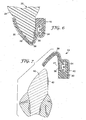
- a tray 30 is formed over the spacer material 26 as illustrated in Fig. 4 .
- the tray 30 is shaped by vacuum forming a sheet of material over the sheet of spacer material 26.
- a suitable material for the tray 30 is a sheet of polycarbonate such as Makrolon brand material from Bayer or Lexan brand polycarbonate from GE having a thickness of 0.06 inch. Other materials, such as polyethyleneterephthalate glycol (“PETG”) may also be used.
- PETG polyethyleneterephthalate glycol
- Heat is applied during the vacuum forming process in order to facilitate conformance of the sheet to the external configuration of the spacer material 26.
- the tray 30 is detached from the spacer material 26.
- the spacer material 26 is then detached from the replica 20 and the appliances 34 and set aside or discarded. During detachment of the spacer material 26 from the replica 20, the appliances 34 remain bonded to the replica teeth.
- the remaining adhesive is more fully cured.
- the appliances 34 are made of metal or other opaque material and if a light-curable adhesive 36 is used, it is preferable to expose the replica 20 to the curing light for a relatively long amount of time such as 3 to 5 minutes to ensure that the adhesive 36 has sufficiently hardened.
- a hand-held curing unit may be used, such as Ortholux XT brand curing unit from 3M Unitek.
- the replica 20 including the replica teeth 22 may be made from a material that transmits actinic radiation.
- Suitable materials include epoxy resins that are transparent or translucent when hardened.
- the material is optically clear.
- An example of a suitable epoxy is E-CAST F-82 clear epoxy resin and No. 302 (or UCE-302) hardener, from United Resin Corporation.
- Other suitable materials include polyesters and urethanes.
- the use of transparent or translucent materials is advantageous in instances where the appliances 34 are made of opaque materials, since the actinic radiation can be transmitted through the replica 20 for curing portions of the adhesive 36 that are located adjacent the middle of the appliance base.
- Actinic radiation can include wavelengths in the visible range, ultraviolet range, infrared range or any combination thereof, in accordance with the type of photoinitiator contained in the adhesive 36.
- stop members 39 are formed to facilitate subsequent positioning of the transfer apparatus relative to the patient's teeth during a bonding procedure.
- the stop members 39 may be made by placing curable material on the replica 20 or alternatively within the channel of the tray 30.
- the stop members 39 are located along the curved longitudinal axis of the tray channel and next to the bottom wall portion of the tray 30 that defines the channel.
- three spaced-apart stop members 39 are made by placing curable material across occlusal sections of the replica dental arch 20.
- One stop member 39 is formed near the center of the replica dental arch 20, while the other two stop members 39 are formed near the right end and left end respectively of the replica dental arch 20.
- a single stop member 39 may be provided that extends along a substantial majority of the curved longitudinal axis of the replica dental arch 20.
- two stop members 39 may be provided, each of which extends along a majority of the left quadrant and the right quadrant respectively of the replica dental arch 20 and follows the curved longitudinal axis of the arch.
- one or more stop members 39 may be provided along the lingual surfaces and/or the facial surfaces of the replica dental arch 20. Lingual and facial stop members may be particularly advantageous to ensuring proper fitting and placement of the transfer apparatus in instances when the patient's maloccluded teeth present diverging tooth angulations.
- the stop members 39 may be made from a variety of materials. Suitable materials include, for example, an orthodontic or dental adhesive, a dental restorative material, or a bite registration material. An example of a suitable bite registration material is "Imprint Bite" bite registration material from 3M Espe.
- the stop members 39 are made of a thermosetting material that, after hardening, does not substantially soften upon contact with heat.
- the stop members 39 transmit actinic radiation and retain their shape over extended periods of time.
- the tray 30 is placed over the replica dental arch 20 including the unhardened stop members 39.
- the tray 30 is pressed toward the replica arch 20 with sufficient force to deform the shape of the unhardened stop members 39 and bring the tray 30 to a desired position relative to the replica 20 as the stop members 39 are flattened.
- This desired position is somewhat adjacent the replica 20, but is sufficiently spaced from the replica 20 so that a quantity of matrix material may be received between the tray 30 and the replica 20 as described below.
- the stop members 39 are then allowed to harden. Once hardened, the stop members 39 have a gingival or tooth-facing surface that matches the occlusal surface of the facing occlusal section of the replica tooth or teeth 22.
- a matrix material is then applied, either to the replica 20 or to the channel of the tray 30.
- the matrix material may be applied to the replica 20 as it appears in Fig. 5 , using a syringe, brush or other technique.
- the matrix material may be preferable to invert the tray 30 such that the open side of the channel of the tray 30 is facing upwardly as shown in Fig. 6 . If the tray 30 is inverted, the tray 30 is not initially trimmed along the outermost distal sides (corresponding to the ends of the dental arch) so that the liquid matrix material is contained within the tray channel.
- the replica 20 is positioned in the tray 30 such that the matrix material 40 is received in the channel of the tray 30 and between the tray 30 and the replica 20.
- the matrix material 40 surrounds the appliance 34 and also extends along the labial and lingual surfaces of the replica tooth 22.
- the matrix material 40 extends along the bottom and side wall surfaces of the tray 30.
- the stop members 39 serve to properly position the tray 30 from the external surfaces of the replica teeth 22 as the matrix material 40 is received in the tray channel. The matrix material 40 is then allowed to harden.
- the matrix material 40 surrounds each appliance 34 and the entire replica arch 20 except in areas near the stop members 39, which remain in contact with the occlusal sections of the replica 20.
- the matrix material 40 and the stop members 39 chemically bond to each other as the matrix material 40 has hardened, so that the stop members 39 are not unintentionally detached during the subsequent steps.
- the matrix material 40 has a relatively low viscosity before hardening so that intimate contact between the matrix material 40 and each appliance 34 is assured.
- the matrix material 40 is able to substantially penetrate in various recesses, cavities and other structural features of each appliance 34 so that a secure connection between the appliance 34 and the matrix material 40 can be established.
- An example of a suitable matrix material having a relatively low viscosity is a silicone material such as "RTV615" silicone material from General Electric as mentioned above.
- the relatively low viscosity of this silicone matrix material also assures that the matrix material will assume a configuration that closely matches the shape of the adjacent surfaces of the replica teeth 22.
- the matrix material 40 may comprise a dental impression material or a bite registration material. Suitable materials include polyvinylsiloxane impression material, such as Memosil 2 brand vinyl polysiloxane material from Heraeus Kulzer Inc., or Peppermint Snap brand clear bite registration material from Discus Dental. If a light-curable adhesive is to be used for bonding the appliances 34 to the patient's teeth, the matrix material 40 is preferably optically clear and transmits actinic radiation without substantial absorption.
- the tray 30, together with the matrix material 40 and the appliances 34 are detached from the replica 20.
- the use of the release agent as mentioned above helps facilitate detaching of the appliances 34 from the corresponding replica teeth 22. Excess material of the tray 30 and excess matrix material 40 are then trimmed as desired as discarded.
- the resultant trimmed transfer apparatus 44 (comprising the tray 30, the matrix material 40, the stop members 39 and the appliances 34) is shown in cross-sectional view in Fig. 7 .
- the patient's teeth that are to receive appliances are isolated using cheek retractors, tongue guards, cotton rolls, dry angles and/or other articles as needed.
- the teeth are then thoroughly dried using pressurized air from an air syringe.
- Etching solution (such as 3M Unitek Transbond XT brand etching gel) is then dabbed onto the teeth in the general area that is to be covered by the appliances 34, taking care to prevent the etching solution from flowing into interproximal contacts or engaging the skin or gingiva.
- the solution is rinsed away from the teeth with a stream of water for fifteen seconds.
- the patient's teeth are then dried by the application of pressurized air from an air syringe (for example, for a time period of thirty seconds) and excess water is removed by suction. Care should also be undertaken to ensure that the saliva does not come in contact with the etched enamel surfaces. Cotton rolls and other absorbent devices are replaced as needed, again making sure that saliva does not contact the etched enamel. Air from the air syringe may then be applied to the teeth again to ensure that the teeth are thoroughly dried.
- a bonding adhesive is applied to the hardened adhesive 36 and/or the selected areas of the patient's teeth.
- the adhesive is a two-component adhesive as depicted in Fig. 7 .
- the first component 41 is a Transbond brand XT moisture insensitive primer
- the second component 43 is Transbond brand Plus self-etching primer, both from 3M Unitek.
- the first component 41 is applied to the hardened adhesive 36 and the second component 43 is applied to the area of the patient's tooth that is to receive the appliance 34.
- the patient's tooth is designated by the numeral 42.
- the tray 30 is then positioned over the corresponding teeth and seated, optionally with a swinging, hinge-type motion. Since the shape of the cavity of the matrix material 40 and the stop members 39 together match the shape of the underlying teeth, the appliances 34 are simultaneously seated against the underlying teeth 42 at precisely the same locations corresponding to the previous position of the appliances 34 on the replica 20.
- the tray 30 has a shape that is complemental to the patient's tooth structure, and has sufficient stiffness to press the appliances 34 against the teeth 42 as the adhesive cures without the application of external pressure.
- external pressure may also be applied to the occlusal, labial and buccal surfaces of the tray 30 until such time as the bonding adhesive has sufficiently hardened.
- finger pressure may be used to firmly press the appliances 34 against the enamel surfaces of the patient's teeth 42.
- Suitable two-component chemical curing adhesives include Sondhi brand Rapid-Set indirect bonding adhesive, Unite brand adhesive and Concise brand adhesive, all from 3M Unitek.
- Sondhi brand Rapid-Set indirect bonding adhesive Unite brand adhesive
- Concise brand adhesive all from 3M Unitek.
- a resin-modified glass ionomer cement may be employed.
- the tray 30 is carefully removed from the patient's dental arch.
- the tray 30 is first separated from the matrix material 40, which remains in place over the dental arch along with the appliances 34.
- the matrix material 40 is detached from the appliances 34.
- a hand instrument such as a scaler may be used to help hold each appliance 34 against the surface of the respective tooth 42 of the patient as the matrix material 40 is peeled away from the appliances 34.
- the use of a scaler to help avoid fracturing the fresh adhesive bond is optional.
- the tray 30 may be separated from the matrix material 40 before the bonding adhesive has hardened. This option is particularly useful when the bonding adhesive is a light-curable adhesive.
- an archwire is placed in the slots of the appliances 34 and ligated in place.
- Suitable ligation devices include tiny, elastic O-rings as well as sections of wire that are tied in a loop around the appliances 34.
- the appliances 34 may be self-ligating appliances that include a latch for releasably engaging the archwire such as those described in U.S. Patent no. 6,302,688 and PCT Publication No. WO02/089693 .
- the hardened adhesive 36 provides a contoured bonding surface for the base of the corresponding appliance 34.
- the configuration of this bonding surface closely matches the shape of the patient's tooth surface and consequently facilitates the subsequent bond (using the bonding adhesive components 41, 43) that is established between the appliance 34 and the tooth 42.
- the bonding surface reduces the likelihood that the appliance 34 will become unintentionally detached from the tooth during the course of treatment.
- the use of the spacer material 26 in combination with the stop members 39 in the method described above is a significant advantage in that an appropriate region for receiving matrix material 40 in the tray 30 is provided.
- the spacer material 26 and the stop members 39 can be shaped as needed to provide precisely the volume and configuration of region as may be desired.
- the spacer material 26 and the stop members 39 may help ensure that a uniform thickness of matrix material is subsequently provided around the substantial extent of the tooth 42 with the exception of the areas adjacent the appliance 34 and the occlusal section of the dental arch adjacent the stop members 39.
- the use of the spacer material 26 facilitates the use of a matrix material having a relatively low viscosity, such as a matrix material having a liquid consistency.
- the tray 30 is relatively stiff, and consequently maintains its shape during forming of the matrix material 40.
- the transfer apparatus 44 is constructed such that the tray 30 (other than the stop members 39) does not directly contact the patient's teeth or gingival tissue. Instead, only the matrix material 40 and the stop members 39 come into contact with the patient's teeth.
- the relatively soft matrix material 40 is flexible and can accommodate a limited amount of tooth movement.
- the teeth of the patient may have slightly shifted between the time that the impressions are taken and the time that the transfer apparatus 44 is fitted in the patient's oral cavity for bonding the appliances 34.
- the matrix material 40 has sufficient flexibility to comply with small shifts or adjustments in the patient's tooth positions, so that the appliances 34 are properly bonded to the intended, pre-determined locations on the patient's tooth.
- the matrix material 40 preferably has a viscosity before curing that is less than about 60,000 cp. More preferably, the matrix material 40 has a viscosity before curing that is less than about 25,000 cp. Most preferably, the matrix material 40 has a viscosity before curing that is less than about 8000 cp.
- the matrix material 40 has a Shore A hardness that is in the range of about 10 to about 80, more preferably in the range of about 30 to about 60 and most preferably in the range of about 40 to about 50.
- the stop members 39 are relatively inflexible and have a Shore A hardness that is greater than the Shore A hardness of the matrix material 40.
- the stop members 39 have a Shore A hardness that is greater than about 60 and more preferably is greater than about 90.
- the spacer material 26 enhances control over construction of the transfer apparatus, including the resultant shape of the tray 30 and the contained matrix material 40.
- the spacer material 26 enables the resultant thickness of the matrix material 40 to be relatively uniform and preferably relatively thin. This uniform thickness of relatively small dimension facilitates curing of a photocurable adhesive used to bond the appliances to the patient's teeth.
- the uniform thickness of matrix material 40 helps to ensure that the light-curable adhesive beneath each appliance 34 is sufficiently cured to the same extent from one appliance 34 to the next. In this manner, the user need not compensate for varying thicknesses of matrix material and the curing times associated with each quantity of adhesive need not vary from one appliance 34 to the next.
- FIG. 8 and 9 Another embodiment of the invention is illustrated in Figs. 8 and 9 . Except as described below, this embodiment is identical to the embodiment set out above in connection with Figs. 1-7 .
- a spacer material 26a is similar to the spacer material 26 except that the spacer material has one or more openings 29a that extend along the occlusal sections of the replica teeth 22.
- the spacer material 26a may have three openings 29a that are located (with respect to the replica 20) in approximately the same positions as the stop members 39 shown in Fig. 5 .
- An interconnecting web (not shown) of the spacer material 26a extends between adjacent openings 29a and over remaining regions of the occlusal sections of the replica teeth 22.
- the spacer material 26a also includes cavities (such as cavity 28a) that are similar to the cavities 28 described above.
- a tray 30a is formed over the spacer material 26a (including over the openings 29a) as shown in Fig. 9 .
- This forming process is essentially the same as the forming process described in connection with Fig. 4 , except that in this instance a portion of the tray material is drawn into the openings 29a and contacts the adjacent, occlusal sections of the replica teeth 22.
- Each of these portions that are drawn into the openings 29a provides a stop member 31a that, in use, functions in a manner similar to the stop members 39 set out above.
- the stop members 31a are integrally connected to a bottom wall portion of the tray 30a and together form a single, unitary body, the handling of separate components during assembly of the transfer apparatus is eliminated.
- a bonding composition may be applied to the base of each appliance 34 by the manufacturer and then packaged in a container for shipment to the practitioner, as described in published U.S. patent application no. 2005-0074716, April 7, 2005 , entitled "Apparatus for Indirect Bonding of Orthodontic Appliances and Method of Making the Same".
- the practitioner can simply remove the transfer apparatus from the container and immediately place the appliances on the patient's teeth.
- the bonding composition of at least one appliance 34 may differ from the bonding composition of at least one other appliance 34 in the transfer apparatus in terms of composition, properties or characteristics, as described in published U.S. patent application no. 2005-0133384, June 23, 2005 entitled “Packaged Orthodontic Assembly with Adhesive Precoated Appliances", such that the bonding composition can be tailored to enhance the bond between the particular selected appliance 34 and its intended tooth.
- the transfer apparatus may be used for bonding only a single appliance to a patient's tooth.
- a portion of the transfer apparatus described above may be used to bond a single appliance to a single tooth subsequent to the time that other appliances are bonded, such as in instances where access to the tooth is initially hindered by other teeth.
- a portion of the transfer apparatus described above may be used to re-bond an appliance that has unintentionally debonded from the tooth, or to bond a new appliance to a tooth to replace the original appliance.
Landscapes
- Health & Medical Sciences (AREA)
- Oral & Maxillofacial Surgery (AREA)
- Dentistry (AREA)
- Epidemiology (AREA)
- Life Sciences & Earth Sciences (AREA)
- Animal Behavior & Ethology (AREA)
- General Health & Medical Sciences (AREA)
- Public Health (AREA)
- Veterinary Medicine (AREA)
- Chemical & Material Sciences (AREA)
- Engineering & Computer Science (AREA)
- Manufacturing & Machinery (AREA)
- Materials Engineering (AREA)
- Dental Tools And Instruments Or Auxiliary Dental Instruments (AREA)
Claims (10)
- Verfahren zur Herstellung eines Transfergeräts zur kieferorthopädischen indirekten Verbindung, umfassend:Bereitstellung eines Abdruckes des Gebisses eines Patienten;Aufbringen eines Abstandsmaterials über dem Abdruck des Gebisses des Patienten, worin das Abstandsmaterial zumindest einen Hohlraum aufweist;Platzieren einer orthodontischen Apparatur in einem Hohlraum des Abstandsmaterials in einer solchen Orientierung, dass eine Basis der Apparatur mit einem Abdruckzahn des Gebissabdruckes in Berührung ist;Bilden einer Schale über dem Abstandsmaterial,Entfernen der Schale von dem Abstandsmaterial;Lösen des Abstandsmaterials von dem Abdruck;Leiten einer Menge eines Matrixmaterials zumindest auf die Schale und/oder auf den Abdruck; undPlatzieren der Schale über dem Abdruck, so dass sich das Matrixmaterial zwischen der Schale und dem Abdruck befindet.
- Verfahren zur Herstellung eines Transfergeräts zur kieferorthopädischen indirekten Verbindung, umfassend:Bereitstellung eines Abdruckes des Gebisses eines Patienten;Platzieren einer orthodontischen Apparatur in einem Hohlraum des Abstandsmaterials, worin das Abstandsmaterial zumindest einen Hohlraum aufweist;Aufbringen des Abstandsmaterials über dem Abdruck des Gebisses des Patienten,worin sich die orthodontische Apparatur in einer solchen Orientierung in dem Hohlraum befindet, dass eine Basis der Apparatur mit einem Abdruckzahn des Gebissabdruckes in Berührung ist;Bilden einer Schale über dem Abstandsmaterial,Entfernen der Schale von dem Abstandsmaterial;Lösen des Abstandsmaterials von dem Abdruck;Leiten einer Menge eines Matrixmaterials zumindest auf die Schale und/oder auf den Abdruck; undPlatzieren der Schale über dem Abdruck, so dass sich das Matrixmaterial zwischen der Schale und dem Abdruck befindet.
- Verfahren zur Herstellung eines Transfergeräts zur kieferorthopädischen indirekten Verbindung nach Anspruch 1 oder 2 und die vorübergehende Fixierung der Basis der Apparatur an dem Abdruckzahn des Abdrucks umfassend.
- Verfahren zur Herstellung eines Transfergeräts zur kieferorthopädischen indirekten Verbindung nach Anspruch 3, worin die Bildung einer Schale über dem Abstandsmaterial die Bildung einer Schalung über dem Abstandsmaterial nach der vorübergehenden Fixierung der Apparatur an dem Abdruckzahn des Abdrucks umfasst.
- Verfahren zur Herstellung eines Transfergeräts zur kieferorthopädischen indirekten Verbindung nach Anspruch 1 oder 2, worin die Leitung einer Menge von Matrixmaterial zumindest auf die Schale und/oder den Abdruck das zumindest teilweise Umschließen der orthodontischen Apparatur mit dem Matrixmaterial umfasst.
- Verfahren zur Herstellung eines Transfergeräts zur kieferorthopädischen indirekten Verbindung nach Anspruch 1 oder 2, worin das Abstandsmaterial eine Reihe von Hohlräumen aufweist, die jeweils zur Aufnahme einer jeweiligen orthodontischen Apparatur ausgelegt sind.
- Verfahren zur Herstellung eines Transfergeräts zur kieferorthopädischen indirekten Verbindung nach Anspruch 1 oder 2 und die Einholung von digitalen Daten, die zumindest einen Teil der Konfiguration des Gebisses des Patienten repräsentieren, und die Herstellung des Abstandsmaterials unter Verwendung der digitalen Daten umfassend.
- Verfahren zur Herstellung eines Transfergeräts zur kieferorthopädischen indirekten Verbindung nach Anspruch 7, worin die Herstellung des Abstandsmaterials die Verwendung eines Verfahrens zur schnellen Herstellung eines Prototypen umfasst.
- Verfahren zur Herstellung eines Transfergeräts zur kieferorthopädischen indirekten Verbindung nach Anspruch 7 und die Verwendung von Computersoftware zur Bestimmung der Lokalisation des Hohlraums in dem Abstandsmaterial umfassend.
- Verfahren zur Herstellung eines Transfergeräts zur kieferorthopädischen indirekten Verbindung nach Anspruch 9, worin die Verwendung von Computersoftware zur Bestimmung der Lokalisation des Hohlraums in dem Abstandsmaterial die Zuordnung der Lokalisation des Hohlraums in dem Abstandsmaterial zu dem Gebiss des Patienten umfasst.
Priority Applications (2)
| Application Number | Priority Date | Filing Date | Title |
|---|---|---|---|
| EP18157309.8A EP3360507A1 (de) | 2005-04-04 | 2006-03-28 | Anordnung zur herstellung einer transfervorrichtung |
| EP14187971.8A EP2845560B1 (de) | 2005-04-04 | 2006-03-28 | Verfahren zur Herstellung einer Übertragungsvorrichtung zum indirekten Kleben von kieferorthopädischen Teilen |
Applications Claiming Priority (2)
| Application Number | Priority Date | Filing Date | Title |
|---|---|---|---|
| US11/098,317 US7556496B2 (en) | 2005-04-04 | 2005-04-04 | Method of making indirect bonding apparatus for orthodontic therapy |
| PCT/US2006/011233 WO2006107652A2 (en) | 2005-04-04 | 2006-03-28 | Method of making indirect bonding transfer apparatus for orthodontic therapy |
Related Child Applications (2)
| Application Number | Title | Priority Date | Filing Date |
|---|---|---|---|
| EP14187971.8A Division EP2845560B1 (de) | 2005-04-04 | 2006-03-28 | Verfahren zur Herstellung einer Übertragungsvorrichtung zum indirekten Kleben von kieferorthopädischen Teilen |
| EP18157309.8A Division EP3360507A1 (de) | 2005-04-04 | 2006-03-28 | Anordnung zur herstellung einer transfervorrichtung |
Publications (2)
| Publication Number | Publication Date |
|---|---|
| EP1909684A2 EP1909684A2 (de) | 2008-04-16 |
| EP1909684B1 true EP1909684B1 (de) | 2014-10-08 |
Family
ID=36636214
Family Applications (3)
| Application Number | Title | Priority Date | Filing Date |
|---|---|---|---|
| EP06739798.4A Not-in-force EP1909684B1 (de) | 2005-04-04 | 2006-03-28 | Verfahren zur herstellung eines indirekten verbindungstransfergeräts für die kieferorthopädische therapie |
| EP18157309.8A Withdrawn EP3360507A1 (de) | 2005-04-04 | 2006-03-28 | Anordnung zur herstellung einer transfervorrichtung |
| EP14187971.8A Not-in-force EP2845560B1 (de) | 2005-04-04 | 2006-03-28 | Verfahren zur Herstellung einer Übertragungsvorrichtung zum indirekten Kleben von kieferorthopädischen Teilen |
Family Applications After (2)
| Application Number | Title | Priority Date | Filing Date |
|---|---|---|---|
| EP18157309.8A Withdrawn EP3360507A1 (de) | 2005-04-04 | 2006-03-28 | Anordnung zur herstellung einer transfervorrichtung |
| EP14187971.8A Not-in-force EP2845560B1 (de) | 2005-04-04 | 2006-03-28 | Verfahren zur Herstellung einer Übertragungsvorrichtung zum indirekten Kleben von kieferorthopädischen Teilen |
Country Status (3)
| Country | Link |
|---|---|
| US (1) | US7556496B2 (de) |
| EP (3) | EP1909684B1 (de) |
| WO (1) | WO2006107652A2 (de) |
Families Citing this family (49)
| Publication number | Priority date | Publication date | Assignee | Title |
|---|---|---|---|---|
| US8308478B2 (en) * | 2005-03-01 | 2012-11-13 | Dentsply International Inc. | Methods for indirect bonding of orthodontic appliances |
| WO2007005490A2 (en) | 2005-06-30 | 2007-01-11 | Implant Innovations, Inc. | Method for manufacturing dental implant components |
| US11219511B2 (en) | 2005-10-24 | 2022-01-11 | Biomet 3I, Llc | Methods for placing an implant analog in a physical model of the patient's mouth |
| US8257083B2 (en) | 2005-10-24 | 2012-09-04 | Biomet 3I, Llc | Methods for placing an implant analog in a physical model of the patient's mouth |
| US8021146B2 (en) * | 2006-06-07 | 2011-09-20 | 3M Innovative Properties Company | Apparatus and methods for controlling moisture during orthodontic indirect bonding procedures |
| US7364428B2 (en) * | 2006-06-07 | 2008-04-29 | 3M Innovative Properties Company | Orthodontic indirect bonding tray with moisture control |
| US7473096B2 (en) | 2006-06-21 | 2009-01-06 | 3M Innovative Properties Company | Orthodontic adhesive dispensing assembly |
| US7726968B2 (en) * | 2007-03-22 | 2010-06-01 | 3M Innovative Properties Company | Methods and assemblies for making an orthodontic bonding tray using rapid prototyping |
| US8439671B2 (en) * | 2007-03-22 | 2013-05-14 | 3M Innovative Properties Company | Methods and apparatus for bonding orthodontic appliances using photocurable adhesive material |
| US7845938B2 (en) * | 2007-03-22 | 2010-12-07 | 3M Innovative Properties Company | Indirect bonding trays for orthodontic treatment and methods for making the same |
| US8206153B2 (en) | 2007-05-18 | 2012-06-26 | Biomet 3I, Inc. | Method for selecting implant components |
| US8777612B2 (en) | 2007-11-16 | 2014-07-15 | Biomet 3I, Llc | Components for use with a surgical guide for dental implant placement |
| JP2011505973A (ja) * | 2007-12-13 | 2011-03-03 | スリーエム イノベイティブ プロパティズ カンパニー | 部分的に硬化した組成物を有する歯科矯正用物品並びにその使用及び製造方法 |
| CN101969877B (zh) * | 2007-12-21 | 2014-01-29 | 3M创新有限公司 | 基于简化图像的正畸治疗监测 |
| KR101536543B1 (ko) | 2008-04-15 | 2015-07-14 | 바이오메트 쓰리아이 엘엘씨 | 정확한 뼈와 연조직 디지털 치아 모델의 형성 방법 |
| EP3415112B1 (de) | 2008-04-16 | 2022-05-25 | Biomet 3I, LLC | Verfahren zur virtuellen entwicklung einer chirurgischen führung für zahnimplantate |
| EP2462893B8 (de) | 2010-12-07 | 2014-12-10 | Biomet 3i, LLC | Universelles Abtastelement zur Verwendung auf Zahnimplantaten und Modellimplantaten |
| WO2012129143A1 (en) | 2011-03-24 | 2012-09-27 | 3M Innovative Properties Company | Dental adhesive comprising a coated polymeric component |
| CA2833215C (en) | 2011-05-16 | 2018-02-27 | Biomet 3I, Llc | Temporary abutment with combination of scanning features and provisionalization features |
| US9452032B2 (en) | 2012-01-23 | 2016-09-27 | Biomet 3I, Llc | Soft tissue preservation temporary (shell) immediate-implant abutment with biological active surface |
| US9089382B2 (en) | 2012-01-23 | 2015-07-28 | Biomet 3I, Llc | Method and apparatus for recording spatial gingival soft tissue relationship to implant placement within alveolar bone for immediate-implant placement |
| US10813729B2 (en) | 2012-09-14 | 2020-10-27 | Biomet 3I, Llc | Temporary dental prosthesis for use in developing final dental prosthesis |
| US9427291B2 (en) | 2012-10-30 | 2016-08-30 | University Of Southern California | Orthodontic appliance with snap fitted, non-sliding archwire |
| US8926328B2 (en) | 2012-12-27 | 2015-01-06 | Biomet 3I, Llc | Jigs for placing dental implant analogs in models and methods of doing the same |
| EP3094283A4 (de) | 2013-12-20 | 2018-01-24 | Biomet 3i, LLC | Zahnärztliches system zur entwicklung von angepassten prothesen durch abtasten von codierten elementen |
| US9439737B2 (en) | 2014-06-11 | 2016-09-13 | Roberto J. Carrillo Gonzalez | Orthodontic indirect bonding tray including stabilization features |
| US9700390B2 (en) | 2014-08-22 | 2017-07-11 | Biomet 3I, Llc | Soft-tissue preservation arrangement and method |
| WO2016144970A1 (en) | 2015-03-09 | 2016-09-15 | Chu Stephen J | Gingival ovate pontic and methods of using the same |
| EP3383309B1 (de) | 2015-12-06 | 2023-08-30 | Brius Technologies, Inc. | System zur zahnumpositionierung und verfahren zur herstellung dieses systems |
| US10828133B2 (en) | 2016-12-02 | 2020-11-10 | Swift Health Systems Inc. | Indirect orthodontic bonding systems and methods for bracket placement |
| CN110366395B (zh) | 2017-01-31 | 2022-06-17 | 斯威夫特健康系统有限公司 | 混合正畸弓丝 |
| US11612458B1 (en) | 2017-03-31 | 2023-03-28 | Swift Health Systems Inc. | Method of tongue preconditioning in preparation for lingual orthodontic treatment |
| WO2018195356A1 (en) | 2017-04-21 | 2018-10-25 | Swift Health Systems Inc. | Indirect bonding trays, non-sliding orthodontic appliances, and registration systems for use thereof |
| US10315353B1 (en) | 2018-11-13 | 2019-06-11 | SmileDirectClub LLC | Systems and methods for thermoforming dental aligners |
| US11007042B2 (en) | 2019-02-06 | 2021-05-18 | Sdc U.S. Smilepay Spv | Systems and methods for marking models for dental aligner fabrication |
| US10482192B1 (en) | 2019-02-12 | 2019-11-19 | SmileDirectClub LLC | Systems and methods for selecting and marking a location on a dental aligner |
| US20200275996A1 (en) | 2019-03-01 | 2020-09-03 | Swift Health Systems Inc. | Indirect bonding trays with bite turbo and orthodontic auxiliary integration |
| KR20220004150A (ko) | 2019-05-02 | 2022-01-11 | 브리우스 테크놀로지스 인코퍼레이티드 | 치과 기기 및 관련 제작 방법 |
| KR102242491B1 (ko) * | 2019-09-10 | 2021-04-20 | 오스템임플란트 주식회사 | 치과용 교정장치 간접 부착기기 |
| US12133785B2 (en) * | 2019-09-18 | 2024-11-05 | Lightforce Orthodontics, Inc. | Process for fabricating a digital bite opening appliance during orthodontic treatment |
| CN114727853B (zh) | 2019-10-31 | 2024-10-01 | 斯威夫特健康系统有限公司 | 间接正畸粘合系统和方法 |
| JP2023529942A (ja) | 2020-06-11 | 2023-07-12 | スウィフト・ヘルス・システムズ・インコーポレイテッド | 非滑り歯列弓形態を伴う歯列矯正器具 |
| US12144700B2 (en) | 2020-11-05 | 2024-11-19 | Brius Technologies, Inc. | Dental appliances and associated systems and methods |
| WO2022192409A2 (en) * | 2021-03-12 | 2022-09-15 | Swift Health Systems Inc. | Indirect orthodontic bonding systems and methods |
| US11504212B2 (en) | 2021-03-25 | 2022-11-22 | Brius Technologies, Inc. | Orthodontic treatment and associated devices, systems, and methods |
| US20220338960A1 (en) * | 2021-04-26 | 2022-10-27 | Brian C. Reising | Orthodontic appliance and method of forming and applying same |
| EP4395687A4 (de) | 2021-09-03 | 2025-07-02 | Swift Health Systems Inc | Orthodontische vorrichtung mit nichtgleitender fussgewölbeform |
| WO2023033870A1 (en) | 2021-09-03 | 2023-03-09 | Swift Health Systems Inc. | Method of administering adhesive to bond orthodontic brackets |
| USD1043994S1 (en) | 2022-01-06 | 2024-09-24 | Swift Health Systems Inc. | Archwire |
Family Cites Families (26)
| Publication number | Priority date | Publication date | Assignee | Title |
|---|---|---|---|---|
| US4360341A (en) * | 1981-03-16 | 1982-11-23 | Dellinger Eugene L | Orthodontic method for treating malocclusion |
| US4501554A (en) * | 1983-07-25 | 1985-02-26 | Hickham John H | Two tray indirect bonding system for labial and lingual brackets |
| US4551096A (en) * | 1983-12-19 | 1985-11-05 | Dellinger Eugene L | Orthodontic apparatus and method for treating malocclusion |
| US4657508A (en) * | 1983-12-19 | 1987-04-14 | Dellinger Eugene L | Orthodontic apparatus and method for treating malocclusion |
| US5015180A (en) * | 1989-03-01 | 1991-05-14 | Minnesota Mining And Manufacturing Company | Dental article containing light-curable paste |
| US4978007A (en) * | 1989-05-10 | 1990-12-18 | Minnesota Mining And Manufacturing Company | Packaging curable materials |
| US5354199A (en) * | 1991-08-02 | 1994-10-11 | Minnesota Mining And Manufacturing Company | Adhesive for packaged orthodontic appliance |
| DE69215228T2 (de) * | 1991-08-02 | 1997-06-12 | Minnesota Mining & Mfg | Verpackter dentaler artikel |
| US5863198A (en) * | 1996-09-23 | 1999-01-26 | Doyle; Walter A. | Orthodontic bracket placement jig |
| US6705863B2 (en) * | 1997-06-20 | 2004-03-16 | Align Technology, Inc. | Attachment devices and methods for a dental appliance |
| JP3118213B2 (ja) * | 1997-09-26 | 2000-12-18 | 俊明 広 | 歯科矯正装置のブラケット取り付け方法 |
| US5971754A (en) * | 1998-07-30 | 1999-10-26 | Sondhi; Anoop | Indirect bonding method and adhesive for orthodontic treatment |
| US6123544A (en) * | 1998-12-18 | 2000-09-26 | 3M Innovative Properties Company | Method and apparatus for precise bond placement of orthodontic appliances |
| US6302688B1 (en) * | 1999-09-27 | 2001-10-16 | 3M Innovative Properties Company | Orthodontic appliance with self-releasing latch |
| US6582226B2 (en) | 1999-09-27 | 2003-06-24 | 3M Innovative Properties Company | Orthodontic appliance with self-releasing latch |
| US6554613B1 (en) * | 2000-04-19 | 2003-04-29 | Ora Metrix, Inc. | Method and apparatus for generating an orthodontic template that assists in placement of orthodontic apparatus |
| US6648640B2 (en) * | 1999-11-30 | 2003-11-18 | Ora Metrix, Inc. | Interactive orthodontic care system based on intra-oral scanning of teeth |
| MXPA01008721A (es) * | 1999-12-29 | 2003-06-24 | Ormco Corp | Metodo y aparato para la formacion de aparato ortodontico a la medida. |
| JP3771498B2 (ja) | 2000-04-19 | 2006-04-26 | オラメトリックス インコーポレイテッド | 歯列矯正装置を配置するための方法およびシステム |
| US6607382B1 (en) * | 2000-09-21 | 2003-08-19 | Align Technology, Inc. | Methods and systems for concurrent tooth repositioning and substance delivery |
| US7155373B2 (en) * | 2002-02-22 | 2006-12-26 | 3M Innovative Properties Company | Selection of orthodontic brackets |
| US20040166462A1 (en) * | 2003-02-26 | 2004-08-26 | Align Technology, Inc. | Systems and methods for fabricating a dental template |
| US7020963B2 (en) * | 2003-05-02 | 2006-04-04 | 3M Innovative Properties Company | Method and apparatus for indirect bonding of orthodontic appliances |
| US7188421B2 (en) * | 2003-05-02 | 2007-03-13 | 3M Innovative Properties Company | Orthodontic appliances having a contoured bonding surface |
| US7137812B2 (en) * | 2003-10-03 | 2006-11-21 | 3M Innovative Properties Company | Apparatus for indirect bonding of orthodontic appliances and method of making the same |
| US20050133384A1 (en) * | 2003-12-19 | 2005-06-23 | 3M Innovative Properties Company | Packaged orthodontic assembly with adhesive precoated appliances |
-
2005
- 2005-04-04 US US11/098,317 patent/US7556496B2/en active Active
-
2006
- 2006-03-28 EP EP06739798.4A patent/EP1909684B1/de not_active Not-in-force
- 2006-03-28 EP EP18157309.8A patent/EP3360507A1/de not_active Withdrawn
- 2006-03-28 EP EP14187971.8A patent/EP2845560B1/de not_active Not-in-force
- 2006-03-28 WO PCT/US2006/011233 patent/WO2006107652A2/en not_active Ceased
Also Published As
| Publication number | Publication date |
|---|---|
| WO2006107652A2 (en) | 2006-10-12 |
| US20060223031A1 (en) | 2006-10-05 |
| EP2845560A3 (de) | 2015-04-08 |
| EP3360507A1 (de) | 2018-08-15 |
| EP2845560A2 (de) | 2015-03-11 |
| WO2006107652A3 (en) | 2007-03-01 |
| US7556496B2 (en) | 2009-07-07 |
| EP2845560B1 (de) | 2018-02-28 |
| EP1909684A2 (de) | 2008-04-16 |
Similar Documents
| Publication | Publication Date | Title |
|---|---|---|
| EP1909684B1 (de) | Verfahren zur herstellung eines indirekten verbindungstransfergeräts für die kieferorthopädische therapie | |
| EP1865878B1 (de) | Orthodontisches indirektes bonding-gerät mit positionierungsanschlagselementen | |
| US7762815B2 (en) | Method of making an indirect bonding tray for orthodontic treatment | |
| EP1620032B1 (de) | Verfahren zur herstellung einer zahnmedizinischen transfervorrichtung | |
| EP1620031B1 (de) | Orthodontische vorrichtung mit konturierter verbindungsstruktur | |
| US7137812B2 (en) | Apparatus for indirect bonding of orthodontic appliances and method of making the same | |
| EP2124806B1 (de) | Verfahren und anordnungen zur herstellung einer kieferorthopädischen verbindungsschale mit schnellem prototyping |
Legal Events
| Date | Code | Title | Description |
|---|---|---|---|
| PUAI | Public reference made under article 153(3) epc to a published international application that has entered the european phase |
Free format text: ORIGINAL CODE: 0009012 |
|
| 17P | Request for examination filed |
Effective date: 20071022 |
|
| AK | Designated contracting states |
Kind code of ref document: A2 Designated state(s): AT BE BG CH CY CZ DE DK EE ES FI FR GB GR HU IE IS IT LI LT LU LV MC NL PL PT RO SE SI SK TR |
|
| DAX | Request for extension of the european patent (deleted) | ||
| 17Q | First examination report despatched |
Effective date: 20120608 |
|
| GRAP | Despatch of communication of intention to grant a patent |
Free format text: ORIGINAL CODE: EPIDOSNIGR1 |
|
| INTG | Intention to grant announced |
Effective date: 20140203 |
|
| GRAP | Despatch of communication of intention to grant a patent |
Free format text: ORIGINAL CODE: EPIDOSNIGR1 |
|
| INTG | Intention to grant announced |
Effective date: 20140527 |
|
| GRAS | Grant fee paid |
Free format text: ORIGINAL CODE: EPIDOSNIGR3 |
|
| GRAA | (expected) grant |
Free format text: ORIGINAL CODE: 0009210 |
|
| AK | Designated contracting states |
Kind code of ref document: B1 Designated state(s): AT BE BG CH CY CZ DE DK EE ES FI FR GB GR HU IE IS IT LI LT LU LV MC NL PL PT RO SE SI SK TR |
|
| REG | Reference to a national code |
Ref country code: GB Ref legal event code: FG4D |
|
| REG | Reference to a national code |
Ref country code: AT Ref legal event code: REF Ref document number: 690167 Country of ref document: AT Kind code of ref document: T Effective date: 20141015 Ref country code: CH Ref legal event code: EP |
|
| REG | Reference to a national code |
Ref country code: IE Ref legal event code: FG4D |
|
| REG | Reference to a national code |
Ref country code: DE Ref legal event code: R096 Ref document number: 602006043269 Country of ref document: DE Effective date: 20141120 |
|
| REG | Reference to a national code |
Ref country code: NL Ref legal event code: VDEP Effective date: 20141008 |
|
| REG | Reference to a national code |
Ref country code: AT Ref legal event code: MK05 Ref document number: 690167 Country of ref document: AT Kind code of ref document: T Effective date: 20141008 |
|
| REG | Reference to a national code |
Ref country code: LT Ref legal event code: MG4D |
|
| PG25 | Lapsed in a contracting state [announced via postgrant information from national office to epo] |
Ref country code: NL Free format text: LAPSE BECAUSE OF FAILURE TO SUBMIT A TRANSLATION OF THE DESCRIPTION OR TO PAY THE FEE WITHIN THE PRESCRIBED TIME-LIMIT Effective date: 20141008 |
|
| PG25 | Lapsed in a contracting state [announced via postgrant information from national office to epo] |
Ref country code: IS Free format text: LAPSE BECAUSE OF FAILURE TO SUBMIT A TRANSLATION OF THE DESCRIPTION OR TO PAY THE FEE WITHIN THE PRESCRIBED TIME-LIMIT Effective date: 20150208 Ref country code: LT Free format text: LAPSE BECAUSE OF FAILURE TO SUBMIT A TRANSLATION OF THE DESCRIPTION OR TO PAY THE FEE WITHIN THE PRESCRIBED TIME-LIMIT Effective date: 20141008 Ref country code: ES Free format text: LAPSE BECAUSE OF FAILURE TO SUBMIT A TRANSLATION OF THE DESCRIPTION OR TO PAY THE FEE WITHIN THE PRESCRIBED TIME-LIMIT Effective date: 20141008 Ref country code: FI Free format text: LAPSE BECAUSE OF FAILURE TO SUBMIT A TRANSLATION OF THE DESCRIPTION OR TO PAY THE FEE WITHIN THE PRESCRIBED TIME-LIMIT Effective date: 20141008 Ref country code: PT Free format text: LAPSE BECAUSE OF FAILURE TO SUBMIT A TRANSLATION OF THE DESCRIPTION OR TO PAY THE FEE WITHIN THE PRESCRIBED TIME-LIMIT Effective date: 20150209 |
|
| PG25 | Lapsed in a contracting state [announced via postgrant information from national office to epo] |
Ref country code: GR Free format text: LAPSE BECAUSE OF FAILURE TO SUBMIT A TRANSLATION OF THE DESCRIPTION OR TO PAY THE FEE WITHIN THE PRESCRIBED TIME-LIMIT Effective date: 20150109 Ref country code: CY Free format text: LAPSE BECAUSE OF FAILURE TO SUBMIT A TRANSLATION OF THE DESCRIPTION OR TO PAY THE FEE WITHIN THE PRESCRIBED TIME-LIMIT Effective date: 20141008 Ref country code: LV Free format text: LAPSE BECAUSE OF FAILURE TO SUBMIT A TRANSLATION OF THE DESCRIPTION OR TO PAY THE FEE WITHIN THE PRESCRIBED TIME-LIMIT Effective date: 20141008 Ref country code: SE Free format text: LAPSE BECAUSE OF FAILURE TO SUBMIT A TRANSLATION OF THE DESCRIPTION OR TO PAY THE FEE WITHIN THE PRESCRIBED TIME-LIMIT Effective date: 20141008 Ref country code: PL Free format text: LAPSE BECAUSE OF FAILURE TO SUBMIT A TRANSLATION OF THE DESCRIPTION OR TO PAY THE FEE WITHIN THE PRESCRIBED TIME-LIMIT Effective date: 20141008 Ref country code: AT Free format text: LAPSE BECAUSE OF FAILURE TO SUBMIT A TRANSLATION OF THE DESCRIPTION OR TO PAY THE FEE WITHIN THE PRESCRIBED TIME-LIMIT Effective date: 20141008 |
|
| REG | Reference to a national code |
Ref country code: DE Ref legal event code: R097 Ref document number: 602006043269 Country of ref document: DE |
|
| PG25 | Lapsed in a contracting state [announced via postgrant information from national office to epo] |
Ref country code: RO Free format text: LAPSE BECAUSE OF FAILURE TO SUBMIT A TRANSLATION OF THE DESCRIPTION OR TO PAY THE FEE WITHIN THE PRESCRIBED TIME-LIMIT Effective date: 20141008 Ref country code: CZ Free format text: LAPSE BECAUSE OF FAILURE TO SUBMIT A TRANSLATION OF THE DESCRIPTION OR TO PAY THE FEE WITHIN THE PRESCRIBED TIME-LIMIT Effective date: 20141008 Ref country code: EE Free format text: LAPSE BECAUSE OF FAILURE TO SUBMIT A TRANSLATION OF THE DESCRIPTION OR TO PAY THE FEE WITHIN THE PRESCRIBED TIME-LIMIT Effective date: 20141008 Ref country code: DK Free format text: LAPSE BECAUSE OF FAILURE TO SUBMIT A TRANSLATION OF THE DESCRIPTION OR TO PAY THE FEE WITHIN THE PRESCRIBED TIME-LIMIT Effective date: 20141008 Ref country code: SK Free format text: LAPSE BECAUSE OF FAILURE TO SUBMIT A TRANSLATION OF THE DESCRIPTION OR TO PAY THE FEE WITHIN THE PRESCRIBED TIME-LIMIT Effective date: 20141008 |
|
| PLBE | No opposition filed within time limit |
Free format text: ORIGINAL CODE: 0009261 |
|
| STAA | Information on the status of an ep patent application or granted ep patent |
Free format text: STATUS: NO OPPOSITION FILED WITHIN TIME LIMIT |
|
| 26N | No opposition filed |
Effective date: 20150709 |
|
| PG25 | Lapsed in a contracting state [announced via postgrant information from national office to epo] |
Ref country code: MC Free format text: LAPSE BECAUSE OF FAILURE TO SUBMIT A TRANSLATION OF THE DESCRIPTION OR TO PAY THE FEE WITHIN THE PRESCRIBED TIME-LIMIT Effective date: 20141008 Ref country code: LU Free format text: LAPSE BECAUSE OF FAILURE TO SUBMIT A TRANSLATION OF THE DESCRIPTION OR TO PAY THE FEE WITHIN THE PRESCRIBED TIME-LIMIT Effective date: 20150328 |
|
| REG | Reference to a national code |
Ref country code: CH Ref legal event code: PL |
|
| REG | Reference to a national code |
Ref country code: IE Ref legal event code: MM4A |
|
| PG25 | Lapsed in a contracting state [announced via postgrant information from national office to epo] |
Ref country code: IE Free format text: LAPSE BECAUSE OF NON-PAYMENT OF DUE FEES Effective date: 20150328 Ref country code: CH Free format text: LAPSE BECAUSE OF NON-PAYMENT OF DUE FEES Effective date: 20150331 Ref country code: LI Free format text: LAPSE BECAUSE OF NON-PAYMENT OF DUE FEES Effective date: 20150331 |
|
| REG | Reference to a national code |
Ref country code: FR Ref legal event code: PLFP Year of fee payment: 11 |
|
| PG25 | Lapsed in a contracting state [announced via postgrant information from national office to epo] |
Ref country code: SI Free format text: LAPSE BECAUSE OF FAILURE TO SUBMIT A TRANSLATION OF THE DESCRIPTION OR TO PAY THE FEE WITHIN THE PRESCRIBED TIME-LIMIT Effective date: 20141008 |
|
| REG | Reference to a national code |
Ref country code: FR Ref legal event code: PLFP Year of fee payment: 12 |
|
| PG25 | Lapsed in a contracting state [announced via postgrant information from national office to epo] |
Ref country code: BG Free format text: LAPSE BECAUSE OF FAILURE TO SUBMIT A TRANSLATION OF THE DESCRIPTION OR TO PAY THE FEE WITHIN THE PRESCRIBED TIME-LIMIT Effective date: 20141008 Ref country code: HU Free format text: LAPSE BECAUSE OF FAILURE TO SUBMIT A TRANSLATION OF THE DESCRIPTION OR TO PAY THE FEE WITHIN THE PRESCRIBED TIME-LIMIT; INVALID AB INITIO Effective date: 20060328 |
|
| PG25 | Lapsed in a contracting state [announced via postgrant information from national office to epo] |
Ref country code: TR Free format text: LAPSE BECAUSE OF FAILURE TO SUBMIT A TRANSLATION OF THE DESCRIPTION OR TO PAY THE FEE WITHIN THE PRESCRIBED TIME-LIMIT Effective date: 20141008 |
|
| PG25 | Lapsed in a contracting state [announced via postgrant information from national office to epo] |
Ref country code: BE Free format text: LAPSE BECAUSE OF FAILURE TO SUBMIT A TRANSLATION OF THE DESCRIPTION OR TO PAY THE FEE WITHIN THE PRESCRIBED TIME-LIMIT Effective date: 20141008 |
|
| REG | Reference to a national code |
Ref country code: FR Ref legal event code: PLFP Year of fee payment: 13 |
|
| PGFP | Annual fee paid to national office [announced via postgrant information from national office to epo] |
Ref country code: FR Payment date: 20210210 Year of fee payment: 16 Ref country code: IT Payment date: 20210211 Year of fee payment: 16 |
|
| PGFP | Annual fee paid to national office [announced via postgrant information from national office to epo] |
Ref country code: GB Payment date: 20210317 Year of fee payment: 16 |
|
| GBPC | Gb: european patent ceased through non-payment of renewal fee |
Effective date: 20220328 |
|
| PG25 | Lapsed in a contracting state [announced via postgrant information from national office to epo] |
Ref country code: GB Free format text: LAPSE BECAUSE OF NON-PAYMENT OF DUE FEES Effective date: 20220328 Ref country code: FR Free format text: LAPSE BECAUSE OF NON-PAYMENT OF DUE FEES Effective date: 20220331 |
|
| PG25 | Lapsed in a contracting state [announced via postgrant information from national office to epo] |
Ref country code: IT Free format text: LAPSE BECAUSE OF NON-PAYMENT OF DUE FEES Effective date: 20220328 |
|
| PGFP | Annual fee paid to national office [announced via postgrant information from national office to epo] |
Ref country code: DE Payment date: 20230221 Year of fee payment: 18 |
|
| P01 | Opt-out of the competence of the unified patent court (upc) registered |
Effective date: 20230530 |
|
| REG | Reference to a national code |
Ref country code: DE Ref legal event code: R081 Ref document number: 602006043269 Country of ref document: DE Owner name: SOLVENTUM INTELLECTUAL PROPERTIES CO. (N.D.GES, US Free format text: FORMER OWNER: 3M INNOVATIVE PROPERTIES CO., ST. PAUL, MINN., US |
|
| REG | Reference to a national code |
Ref country code: DE Ref legal event code: R119 Ref document number: 602006043269 Country of ref document: DE |
|
| PG25 | Lapsed in a contracting state [announced via postgrant information from national office to epo] |
Ref country code: DE Free format text: LAPSE BECAUSE OF NON-PAYMENT OF DUE FEES Effective date: 20241001 |
|
| PG25 | Lapsed in a contracting state [announced via postgrant information from national office to epo] |
Ref country code: DE Free format text: LAPSE BECAUSE OF NON-PAYMENT OF DUE FEES Effective date: 20241001 |