EP1909452B1 - An access device routing decive and method thereof supporting stateless address configuration in communication network - Google Patents
An access device routing decive and method thereof supporting stateless address configuration in communication network Download PDFInfo
- Publication number
- EP1909452B1 EP1909452B1 EP20060741920 EP06741920A EP1909452B1 EP 1909452 B1 EP1909452 B1 EP 1909452B1 EP 20060741920 EP20060741920 EP 20060741920 EP 06741920 A EP06741920 A EP 06741920A EP 1909452 B1 EP1909452 B1 EP 1909452B1
- Authority
- EP
- European Patent Office
- Prior art keywords
- access device
- user
- message
- identification information
- user identification
- Prior art date
- Legal status (The legal status is an assumption and is not a legal conclusion. Google has not performed a legal analysis and makes no representation as to the accuracy of the status listed.)
- Not-in-force
Links
Images

Classifications
-
- H—ELECTRICITY
- H04—ELECTRIC COMMUNICATION TECHNIQUE
- H04L—TRANSMISSION OF DIGITAL INFORMATION, e.g. TELEGRAPHIC COMMUNICATION
- H04L61/00—Network arrangements, protocols or services for addressing or naming
- H04L61/50—Address allocation
- H04L61/5007—Internet protocol [IP] addresses
-
- H—ELECTRICITY
- H04—ELECTRIC COMMUNICATION TECHNIQUE
- H04L—TRANSMISSION OF DIGITAL INFORMATION, e.g. TELEGRAPHIC COMMUNICATION
- H04L45/00—Routing or path finding of packets in data switching networks
- H04L45/54—Organization of routing tables
-
- H—ELECTRICITY
- H04—ELECTRIC COMMUNICATION TECHNIQUE
- H04L—TRANSMISSION OF DIGITAL INFORMATION, e.g. TELEGRAPHIC COMMUNICATION
- H04L2101/00—Indexing scheme associated with group H04L61/00
- H04L2101/60—Types of network addresses
- H04L2101/618—Details of network addresses
- H04L2101/659—Internet protocol version 6 [IPv6] addresses
Definitions
- the present invention relates to an access network, and in particular, to a device and method of implementing address configuration in an access network.
- IPv6 stateless configuration is considered a configuration manner newly defined in the IPv6 protocol, by which flexible configuration of a terminal can be achieved and plug&play of a terminal device is made possible.
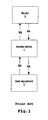
- Fig. 1 shows a schematic view of an access network architecture supporting IPv6 user equipment, in which there are comprised a plurality of user equipment (only user equipment 3 is shown for simplicity), an access device (or access node) 1 and a router 2.
- access device 1 can be a layer 2 device with some layer 3 functionalities.
- IPDSLAM IP Digital Subscriber Line Access Multiplexer
- Router 2 can be an IPv6 protocol-based edge router (IPv6 BRAS/Edge Router).
- IPv6 stateless configuration user equipment 3 first generates a local link transfer address by itself, and then multicasts, by taking the address as a source address, address configuration information called router solicitation (RS) via access device 1 to all routers 2 on the local link. Router 2 responds to the solicitation with a router advertisement (RA) message which contains an aggregate global unicast transfer address prefix and other relevant configuration information.
- RS router solicitation
- RA router advertisement
- User equipment 3 combines the global address prefix which it gets via access device 1 from router 2 and an interface identifier generated by itself to generate a global address automatically. And through repeated address detection, user equipment 3 can communicate with other user equipment on the Internet.
- IP addresses of all hosts within a network can be changed without manual intervention.
- IPv6 stateless configuration which was generated in open network applications, goes on the premise that neighboring nodes trust each other. Directly applying this mechanism in an access network will cause security and scalability problems of the access network, especially for a layer 2 access device or an enhanced layer 2 access device with some layer 3 functionalities. Detailed description will be given below.
- edge router 2 advertises a dedicated address prefix to each DSL line.
- access device 1 could easily realize an IP address anti-spoofing filter by inspecting the prefix of a packet' s source and 2) access device 1 could avoid the scalability problem by only relaying the RA message from edge router 2 to a particular DSL line.
- the technical problem to be solved in the prior art is how to support such configuration of allocating one address prefix for each DSL line configuration in a broadband access network employing a layer 2 access device with some layer 3 functionalities.
- both VLAN-based cross-connected mode and MAC address-based bridge mode can be employed in data forwarding.
- access device 1 may operate in cross-connected mode, VLAN (virtual local area network) is configured to identify and separate traffic or information (e.g. RS message) from different DSL lines.
- traffic or information e.g. RS message
- IPv6-based edge router 2 the RA message containing a particular address prefix will be only sent to the DSL line identified by a certain VLAN.
- cross-connect mode no modification is needed in access device 1.
- cross-connect mode means that the user's VLAN information could be maintained at network side and different customers will not share the same VLAN identifier.
- VLAN stacking is an alternative solution to solve the scalability problem of standard VLAN solution. By using VLAN stacking, it is possible to scale up to support 1024*1024 distinct VLANs. Unfortunately, VLAN stacking has not been standardized, and thus is not supported by all access devices and Ethernets.
- bridge mode When access device 1 operates in bridge mode, since DLS line identifiers cannot be transferred to network side, edge router 2 cannot allocate a particular address prefix for each DSL line correctly.
- bridge mode means that since the DSL line information of user equipment cannot be maintained at network side, it is impossible to effectively distinguish different user equipment.
- XP 15037780 discloses a DHCPv6 Relay Agent Information Option which extends a set of DHCPv6 options as defined in The Internet Engineering Task Force (IETF) RFC 3315 and 3376.
- IETF Internet Engineering Task Force
- XP 15039813 discloses a DHCPv6 Relay Agent Remote ID Option.
- the present invention is proposed to solve the aforesaid problems in the prior art.
- an IPv6 edge router can get the ID information of a DSL line and use the information to allocate a proper IPv6 address prefix for each DSL user.
- VLAN or VLAN-stacking
- VLAN-stacking realizes one-address prefix-per-line using Ethernet technology. This requires all Ethernet devices between the user equipment and the edge router support the VLAN mechanism and the access node needs to operate in cross-connect mode.
- the present invention realizes one-address prefix-per-line using IP technology, i.e., by encapsulating the DSL line ID information into RA and RS messages.
- This solution allows the access node to operate in bridge mode or one VLAN to be shared between different users. But this solution requires both the access node and the edge router should support this RS/RA extension.
- a method for address configuration in an access device in an IPv6 protocol supported communication network comprising: receiving a user solicitation message according to the IPv6 neighbor discovery protocol (NDP) from user equipment ; adding user identification information identifying the user equipment to the user solicitation message, to generate a solicitation message to which the user identification information is added; and sending the solicitation message to which the user identification information is added to a router.
- NDP IPv6 neighbor discovery protocol
- the method further comprises the steps of: receiving a router response message from the router; separating address prefix information and the user identification information from the router response message; and sending the address prefix information to corresponding user equipment in accordance with the user identification information.
- an access device for address configuration for user equipment in an IPv6 protocol supported communication network, the access device comprising: first reception means for receiving a user solicitation message according to the IPv6 NDP from user equipment; message combination means for adding user identification information identifying the user equipment to the user solicitation message, to generate a solicitation message to which the user identification information is added; and first sending means for sending the solicitation message to which the user identification information is added to an edge router.
- the access device further comprises: second reception means for receiving a router response message from the router; message separation means for separating address prefix information and the user identification information from the router response message; and second sending means for sending the address prefix information to corresponding user equipment in accordance with the user identification information.
- a method for address configuration in a routing device of an IPv6 protocol supported communication network comprising: receiving a user solicitation message according to the IPv6 NDP from an access device; separating user identification information from the user solicitation message; allocating a user-specific address prefix based on the user identification information; adding the user-specific address prefix and the user identification information to a router response message; and sending the router response message to which the user identification information and the specific address prefix are added to the access device.
- a routing device for address configuration for user equipment in an IPv6 protocol supported communication network, the routing device comprising: reception means for receiving a user solicitation message according to the IPv6 NDP from an access device; message separation means for separating user identification information from the user solicitation message; allocation means for allocating a user-specific address prefix based on relay agent identification (ID) and a port identifier; message combination means for adding the user-specific address prefix, the relay agent identification and the port identifier to a router response message; and sending means for sending the router response message to which user identification information and specific address prefix are added, to the access device.
- ID relay agent identification
- sending means for sending the router response message to which user identification information and specific address prefix are added, to the access device.
- the present invention achieve stateless address configuration for IPv6 service by allocating a dedicated address prefix for each data subscriber line, thereby solving the security and scalability problem caused by applying the solution of the prior art to an access network directly. It allows an access device to operate in bridge mode when the VLAN (VLAN stacking) is not supported by the access device and an EMAN network or when multiple lines share the same VLAN. Furthermore, the present invention makes no modification to user equipment. User equipment can directly employ the standard IPv6 protocol stack.
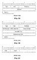
- Figs. 2A-2B show schematic views of message formats of a user solicitation message (e.g. router solicitation (RS) message) from user equipment 3 shown in Fig. 1 and a router response message (e.g. router advertisement (RA) message) from router 2 shown in Fig. 1 . Both of these two messages belong to the IPv6 neighbor discovery protocol and are encapsulated in an ICMPv6 packet.
- RS router solicitation
- RA router advertisement
- the 1 st byte is used for indicating type; the 2 nd byte is used for indicating code; the 3 rd -4 th bytes are checksum; the 5 th -8 th bytes are reserved bytes; and subsequent bytes are options.
- the 1 st byte is used for indicating type; the 2 nd byte is used for indicating code; the 3 rd -4 th bytes are checksum; the 5 th byte is Cur Hop Limit; in the 6 th byte, the 1 st bit denotes M, the 2 nd bit denotes O, and the 3 rd -8 th bits are used for reservation; the 7 th -8 th bytes denote router lifetime; the 9 th -12 th bytes denote reachable time; the 13 th -16 th bytes denote retransmission timer; and subsequent bytes are options.
- IPv6 Neighbor Discovery messages include zero or more options, some of which may appear multiple times in the same message. All options are of the form shown in Fig. 2C : wherein, Type: the type is an 8-bit identifier.
- the RFC 2461 standard has defined the type of option as shown in Table 1: Table 1: Option Name Type Source Link-Layer Address 1 Target Link-Layer Address 2 Prefix Information 3 Redirected Header 4 MTU (Maximum Transmission Unit) 5 Length: 8-bit unsigned integer.
- the length of the option (including the fields of type and length) is in units of 8 bytes. The value 0 is invalid. Access device 1 must discard an ND packet that contains an option with the value 0 of length.
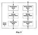
- a concrete message format thereof is as shown in Fig. 3 , wherein, Type: 6 Length: 3 (in units of 8 bytes)
- Link Identifier This field uniquely identifies a line (port) under an access device.
- the MAC address of each DSL line port can be used as the identifier. If the DSL line port does not have a MAC address, any other local unique layer 2 identifier can be used by the access node as the identifier.
- Relay Agent ID This field uniquely identifies an RS/RA message relay agent (i.e., an access device). In an IPv6 access network, this field can employ the IPv6 address (or any other layer 2 or 3 identifier) of the access node used by the service provider for the purpose of network management.
- Fig. 4 is a schematic view of RS/RA solutions for IPv6 stateless configuration in an IPv6-based communication network which employs Ethernet access device (access node) 1 with some IP layer functionalities.
- Fig. 4 shows RS/RA agent solutions for layer 2 Ethernet access device (access node) 1 with some layer 3 (IP layer) functionalities so as to support IPv6 stateless configuration.
- IP layer layer 3
- Fig. 4 shows one (IPv6 protocol supported) user equipment 3, one access device (Ethernet access device with some IP layer functionalities) 1 and one routing device (e.g. IPv6 edge router) 2.
- user equipment 3 sends a user solicitation message (e.g. a router solicitation (RS) message defined in RFC 2461) to access device 1.
- a user solicitation message e.g. a router solicitation (RS) message defined in RFC 2461
- access device 1 adds to the RS message user identification information for identifying the user, which contains the relay agent ID representing access device 1 and the port identifier corresponding to user equipment 3. Access device 1 sends to routing device 2 the RS message to which the user identification information was added.
- Routing device 2 separates the user identification message (including relay agent ID of access device 1 and the port identifier corresponding to user equipment 3) from the received RS message, allocates a particular address prefix (e.g. IPv6 address prefix) based on the relay agent ID and the port identifier, and contains the information (the relay agent ID , the port identifier and the corresponding particular address prefix) in a router response (e.g. a router advertisement (RA) message defined in RFC 2461).
- RA router advertisement
- Access device 1 separates from the RA message option 3 which contains the particular address prefix information and option 6 which contains the relay agent ID and the port identifier. Based on the relay agent ID and the line port which the port identifier indicates, and after option 6 is removed from the RA message, the RA message from which option 6 was removed is sent to user equipment 3 via the line port which the port identifier represents.
- routing device 2 e.g. edge router
- routing device 2 can allocate a dedicated address prefix for each user equipment 3 (or DSL), and access device 2 can avoid the scalability problem which might be caused by flooding the RA message to all DSL lines, and implement pre-prefix-IP address-based anti-spoofing filter (security).
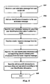
- Fig. 5 shows an access device 1 implementing address configuration for user equipment in an IPv6 protocol-based communication network according to an embodiment of the present invention, which comprises first reception means 11, message combination means 12, first sending means 13, second reception means 14, message separation means 15, and second sending means 16.
- First reception means 11 is for receiving a user solicitation message (e.g. a router solicitation (RS) message defined in RFC 2461) from user equipment.
- a user solicitation message e.g. a router solicitation (RS) message defined in RFC 2461
- Message combination means 12 is for adding user identification information to the user solicitation message, wherein the user identification information may contain relay agent ID representing the access device 1 and a port identifier corresponding to the user equipment (or DSL).
- First sending means 13 is for sending the user solicitation message, to which the user identification information was added, to a routing device (e.g. edge router).
- a routing device e.g. edge router
- Second reception means 14 is for receiving a router response message (e.g. a router advertisement (RA) message defined in RFC 2461) from the routing device, which RA message contains user identification information (may contain a port identifier only or relay agent ID and a port identifier) and a particular address prefix (e.g. IPv6 address prefix) corresponding to the user equipment.
- a router response message e.g. a router advertisement (RA) message defined in RFC 2461
- RA message contains user identification information (may contain a port identifier only or relay agent ID and a port identifier) and a particular address prefix (e.g. IPv6 address prefix) corresponding to the user equipment.
- Message separation means 15 is for separating from the router response message the user identification information and the particular address prefix information.
- the user identification information at least includes a port identifier for identifying the user equipment (or DSL).
- Second sending means 16 is for, based on the user identification information, sending the particular address prefix information via a port indicated by the port identifier to the corresponding user equipment.
- access device 1 is a layer 2 access device with some layer 3 functionalities, and more preferably, is an Ethernet access device.
- message combination means 12 and message separation means 13 (which separates a user identification message from a router solicitation message and combines the former with the latter) can be implemented by adding the solution of option 6 shown in Fig. 3 to an IP neighbor discovery message (RS/RA message) defined in RFC 2461 as shown in 2A-2C or separating the former from the latter.
- RS/RA message IP neighbor discovery message
- Fig. 6 shows a flowchart of a method of implementing address configuration for user equipment in access device 2 in an IPv6 protocol-based communication network according to an embodiment of the present invention.
- a user solicitation message (e.g. a router solicitation (RS) message defined in RFC 2461) is received from user equipment.
- RS router solicitation
- step S102 user identification information is added to the user solicitation message.
- the user identification information may contain relay agent ID representing access device 1 and a port identifier corresponding to the user equipment (or DSL).
- step S103 the user solicitation message to which the user identification information was added is sent to a routing device (e.g. edge router).
- a routing device e.g. edge router
- a router response message (e.g. a router advertisement (RA) message defined in RFC 2461) is received from the routing device, which RA message contains user identification information (may contain a port identifier only or relay agent ID and a port identifier) and a particular address prefix corresponding to user equipment.
- RA message e.g. a router advertisement (RA) message defined in RFC 2461
- step S105 the user identification information and the corresponding particular address prefix information are separated from the router response message.
- the user identification information at least includes a port identifier for identifying user equipment (or DSL).
- step S106 the particular address prefix information is sent via a port indicated by the port identifier to corresponding user equipment in accordance with the user identification message.
- the access device 1 is a layer 2 access device with some layer 3 functionalities, and more preferably, is an Ethernet access device.
- the steps of combining a user identification message with a router solicitation message and separating the former from the latter can be implemented by adding the solution of option 6 shown in Fig. 3 to an IP neighbor discovery message (RS/RA message) defined in RFC 2461 as shown in 2A-2C or separating the former from the latter.
- RS/RA message IP neighbor discovery message
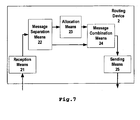
- Fig. 7 shows a routing device 2 implementing address configuration for user equipment 3 in an IPv6 protocol-based communication network according to an embodiment of the present invention, which comprises reception means 21, message separation means 22, allocation means 23, message combination means 24, and sending means 25.
- Reception means 21 is for receiving a user solicitation message (e.g. a router solicitation (RS) message defined in RFC 2461) from access device 2, wherein the RS message contains user identification information which may contain relay agent ID representing access device 1 and a port identifier corresponding to the user equipment (or DSL).
- a user solicitation message e.g. a router solicitation (RS) message defined in RFC 2461
- the RS message contains user identification information which may contain relay agent ID representing access device 1 and a port identifier corresponding to the user equipment (or DSL).
- Message separation means 22 is for separating the user identification information from the user solicitation message.
- Allocation means 23 is for allocating a corresponding particular address prefix (e.g. IPv6 address prefix) based on the user identification information (relay agent ID and port identifier).
- a corresponding particular address prefix e.g. IPv6 address prefix
- Message combination means 24 is for adding the user identification information (may contain a port identifier only or relay agent ID and a port identifier) and the corresponding particular address prefix to a router response message (e.g. a router advertisement (RA) message defined in RFC 2461).
- a router advertisement (RA) message defined in RFC 2461.
- Sending means 25 is for sending the router response message to a corresponding access device based on the relay agent ID.
- access device 1 is a layer 2 access device with some layer 3 functionalities, and more preferably, is an Ethernet access device.
- message separation means 22 which separates the user identification message from the user solicitation message and message combination means 24 which adds the address prefix to the router response message can be implemented by adding the solution of option 6 shown in Fig. 3 to an IP neighbor discovery message (RS/RA message) defined in RFC 2461 as shown in 2A-2C or separating the former from the latter.
- RS/RA message IP neighbor discovery message
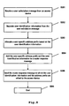
- Fig. 8 shows a flowchart of a method of implementing address configuration for user equipment 3 in routing device 2 in an IPv6 protocol-based communication network, according to an embodiment of the present invention.
- a user solicitation message (e.g. router solicitation (RS) message defined in RFC 2461) is received from access device 2, wherein the RS message contains user identification information which may contain relay agent ID representing access device 1 and a port identifier corresponding to the user equipment (or DSL).
- RS router solicitation
- step S202 the user identification information is separated from the user solicitation message.
- a corresponding particular address prefix (e.g. IPv6 address prefix) is allocated based on the user identification information (relay agent ID and port identifier).
- the user identification information (may contain a port identifier only or relay agent ID and a port identifier) and the particular address prefix are added to a router response message (e.g. a router advertisement (RA) message defined in RFC 2461).
- a router advertisement (RA) message defined in RFC 2461.
- step S205 the router response message is sent to a corresponding access device based on the relay agent ID.
- access device 1 is a layer 2 access device with some layer 3 functionalities, and more preferably, is an Ethernet access device.
- step S202 of separating the user identification message from the user solicitation message and step S204 of adding the address prefix to the router response message can be implemented by adding the solution of option 6 shown in Fig. 3 to an IP neighbor discovery message (RS/RA message) defined in RFC 2461 as shown in 2A-2C or separating the former from the latter.
- RS/RA message IP neighbor discovery message
- the present invention allocates a dedicated address prefix for each user equipment (or DSL) by adding to an RS/RA message user identification information for indicating user equipment, thereby achieving stateless address configuration in IPv6 service and solving the security and scalability problem caused by applying the solutions of the prior art to an access network directly.
Landscapes
- Engineering & Computer Science (AREA)
- Computer Networks & Wireless Communication (AREA)
- Signal Processing (AREA)
- Data Exchanges In Wide-Area Networks (AREA)
Applications Claiming Priority (2)
| Application Number | Priority Date | Filing Date | Title |
|---|---|---|---|
| CN2005100277068A CN1897589B (zh) | 2005-07-13 | 2005-07-13 | IPv6无状态地址配置中的接入装置、路由设备及方法 |
| PCT/CN2006/001032 WO2007006195A1 (en) | 2005-07-13 | 2006-05-19 | An access device routing decive and method thereof supporting stateless address configuration in communication network |
Publications (3)
| Publication Number | Publication Date |
|---|---|
| EP1909452A1 EP1909452A1 (en) | 2008-04-09 |
| EP1909452A4 EP1909452A4 (en) | 2010-03-24 |
| EP1909452B1 true EP1909452B1 (en) | 2012-10-31 |
Family
ID=37609962
Family Applications (1)
| Application Number | Title | Priority Date | Filing Date |
|---|---|---|---|
| EP20060741920 Not-in-force EP1909452B1 (en) | 2005-07-13 | 2006-05-19 | An access device routing decive and method thereof supporting stateless address configuration in communication network |
Country Status (7)
| Country | Link |
|---|---|
| US (1) | US8655990B2 (enExample) |
| EP (1) | EP1909452B1 (enExample) |
| JP (1) | JP4801153B2 (enExample) |
| KR (1) | KR100997075B1 (enExample) |
| CN (1) | CN1897589B (enExample) |
| BR (1) | BRPI0613012A2 (enExample) |
| WO (1) | WO2007006195A1 (enExample) |
Families Citing this family (23)
| Publication number | Priority date | Publication date | Assignee | Title |
|---|---|---|---|---|
| CN100499674C (zh) * | 2006-01-06 | 2009-06-10 | 华为技术有限公司 | 一种路由器下终端设备ip地址的分配方法 |
| US7995524B2 (en) | 2006-09-07 | 2011-08-09 | Industrial Technology Research Institute | Wireless communication system and method |
| US8005080B2 (en) * | 2006-10-23 | 2011-08-23 | Electronics And Telecommunications Research Institute | IPv6 address configuration method in wireless mobile network and apparatus therefor |
| EP2048857A1 (en) * | 2007-10-12 | 2009-04-15 | PacketFront Systems AB | Method of configuring routers using external servers |
| CN101547383B (zh) * | 2008-03-26 | 2013-06-05 | 华为技术有限公司 | 一种接入认证方法及接入认证系统以及相关设备 |
| CN101753635A (zh) * | 2008-12-17 | 2010-06-23 | 华为技术有限公司 | Ipv6地址配置方法和系统 |
| EP2244434B1 (en) * | 2009-04-20 | 2017-06-28 | Alcatel Lucent | Method and apparatus for connecting subscriber devices to an IPV6-capable aggregation network |
| CN101873515B (zh) | 2009-04-21 | 2013-12-04 | 华为技术有限公司 | 无源光网络的ipv6协议消息传输方法、系统及装置 |
| CN102088391B (zh) * | 2009-12-07 | 2013-09-11 | 华为技术有限公司 | 一种IPv6报文的处理方法、设备和系统 |
| CN102143242B (zh) * | 2010-10-21 | 2014-07-09 | 华为技术有限公司 | Ip网络中地址分配方法、设备及系统 |
| CN102694752B (zh) * | 2011-03-21 | 2015-03-11 | 国基电子(上海)有限公司 | 网关设备 |
| CN102724101B (zh) | 2011-03-29 | 2015-01-21 | 华为技术有限公司 | 报文转发方法及系统与中继代理设备 |
| CN103167048A (zh) * | 2011-12-12 | 2013-06-19 | 华为技术有限公司 | 基于IPv6的二层互通的方法、装置和系统 |
| US10965615B2 (en) * | 2012-03-30 | 2021-03-30 | Nokia Solutions And Networks Oy | Centralized IP address management for distributed gateways |
| US20220014495A9 (en) * | 2012-10-11 | 2022-01-13 | Cable Television Laboratories, Inc. | Adaptive prefix delegation |
| CN103037026B (zh) * | 2012-12-10 | 2015-07-22 | 上海斐讯数据通信技术有限公司 | Dhcp服务器地址池自动配置方法、装置及cpe设备 |
| JP6029449B2 (ja) * | 2012-12-17 | 2016-11-24 | 三菱電機株式会社 | スマートメータシステム、管理ルータおよびメータ |
| WO2016032467A1 (en) | 2014-08-27 | 2016-03-03 | Adaptive Spectrum And Signal Alignment, Inc. | Systems, methods, and apparatuses for implementing the virtualization of access node functions |
| CN105591848A (zh) * | 2014-10-20 | 2016-05-18 | 中兴通讯股份有限公司 | 一种IPv6无状态自动配置的认证方法及装置 |
| CN109495594B (zh) | 2017-09-11 | 2022-03-29 | 华为技术有限公司 | 一种数据传输方法、pnf sdn控制器、vnf sdn控制器及系统 |
| CN110417658B (zh) * | 2018-04-28 | 2022-08-12 | 北京京东尚科信息技术有限公司 | 用于边缘路由器的网络接入方法和装置 |
| CN111131548B (zh) * | 2019-12-30 | 2022-06-28 | 奇安信科技集团股份有限公司 | 信息处理方法、装置和计算机可读存储介质 |
| CN114500258B (zh) * | 2021-12-14 | 2023-08-15 | 四川天邑康和通信股份有限公司 | 家庭智能网关下wifi6路由器下ipv6自动上网配置方法 |
Family Cites Families (13)
| Publication number | Priority date | Publication date | Assignee | Title |
|---|---|---|---|---|
| FI109950B (fi) * | 2000-01-20 | 2002-10-31 | Nokia Corp | Osoitteen saanti |
| JP4253520B2 (ja) * | 2003-03-19 | 2009-04-15 | 株式会社日立製作所 | ネットワーク認証装置及びネットワーク認証システム |
| DE50212142D1 (de) * | 2001-02-13 | 2008-06-05 | Nokia Siemens Networks Gmbh | Verfahren und anordnung zum ermitteln der internetprotokolladresse einer endgeräteanordnung |
| US7457253B2 (en) * | 2002-03-26 | 2008-11-25 | Telefonaktiebolaget Lm Ericsson (Publ) | System, an arrangement and a method relating to IP-addressing |
| JP3896897B2 (ja) * | 2002-05-24 | 2007-03-22 | 株式会社日立製作所 | ルータ設定方法およびルータ |
| JP2003348116A (ja) * | 2002-05-28 | 2003-12-05 | Hitachi Ltd | 家庭内ネットワーク向けアドレス自動設定方式 |
| AU2002368088B2 (en) * | 2002-07-08 | 2007-10-18 | Packetfront Sweden Ab | Dynamic port configuration of network equipment |
| JP4034611B2 (ja) * | 2002-07-18 | 2008-01-16 | 東日本電信電話株式会社 | ネットワークシステム及びネットワーク分岐装置 |
| JP4106621B2 (ja) * | 2003-06-20 | 2008-06-25 | 富士通株式会社 | モバイル端末及びルータ及びアドレス登録方法 |
| CN100493073C (zh) * | 2003-07-19 | 2009-05-27 | 华为技术有限公司 | 不同链路层隔离域的邻居发现实现方法 |
| WO2005008994A1 (en) * | 2003-07-23 | 2005-01-27 | Samsung Electronics Co., Ltd. | Method and system for generating ip addresses of access terminals and transmitting messages for generation of ip addresses in an ip system |
| JP2005064570A (ja) * | 2003-08-12 | 2005-03-10 | Hitachi Ltd | ネットワークシステム及びインターネットワーク装置 |
| US8341700B2 (en) | 2003-10-13 | 2012-12-25 | Nokia Corporation | Authentication in heterogeneous IP networks |
-
2005
- 2005-07-13 CN CN2005100277068A patent/CN1897589B/zh not_active Expired - Lifetime
-
2006
- 2006-05-19 US US11/995,499 patent/US8655990B2/en not_active Expired - Fee Related
- 2006-05-19 BR BRPI0613012-7A patent/BRPI0613012A2/pt not_active Application Discontinuation
- 2006-05-19 KR KR20087000894A patent/KR100997075B1/ko not_active Expired - Fee Related
- 2006-05-19 EP EP20060741920 patent/EP1909452B1/en not_active Not-in-force
- 2006-05-19 JP JP2008520690A patent/JP4801153B2/ja not_active Expired - Fee Related
- 2006-05-19 WO PCT/CN2006/001032 patent/WO2007006195A1/zh not_active Ceased
Also Published As
| Publication number | Publication date |
|---|---|
| US8655990B2 (en) | 2014-02-18 |
| CN1897589B (zh) | 2010-12-15 |
| WO2007006195A1 (en) | 2007-01-18 |
| EP1909452A4 (en) | 2010-03-24 |
| JP2009500970A (ja) | 2009-01-08 |
| EP1909452A1 (en) | 2008-04-09 |
| KR20080033938A (ko) | 2008-04-17 |
| US20080244090A1 (en) | 2008-10-02 |
| KR100997075B1 (ko) | 2010-11-30 |
| BRPI0613012A2 (pt) | 2010-12-14 |
| JP4801153B2 (ja) | 2011-10-26 |
| CN1897589A (zh) | 2007-01-17 |
Similar Documents
| Publication | Publication Date | Title |
|---|---|---|
| EP1909452B1 (en) | An access device routing decive and method thereof supporting stateless address configuration in communication network | |
| US11240206B2 (en) | Broadband access for virtual private networks | |
| US8953601B2 (en) | Internet protocol version six (IPv6) addressing and packet filtering in broadband networks | |
| EP2213080B1 (en) | Vrrp and learning bridge cpe | |
| CN1778077B (zh) | 一种用于园区网上的子网间移动性的方法 | |
| US20020165972A1 (en) | Methods and apparatus for use in reducing traffic over a communication link used by a computer network | |
| US6996621B1 (en) | Method for supporting secondary address delivery on remote access servers | |
| US20020038419A1 (en) | Service selection in a shared access network using tunneling | |
| JP2003520535A (ja) | アドレス取得 | |
| CN101213817A (zh) | 从终端的原始mac地址到唯一的本地管理虚拟mac地址的映射 | |
| JP2010506439A (ja) | ブリッジされたネットワークにおけるポイントツーマルチポイント機能 | |
| CN100499674C (zh) | 一种路由器下终端设备ip地址的分配方法 | |
| CN100364289C (zh) | 在基于弹性分组环的网络中实现二层设备互连的方法 | |
| CN101179603B (zh) | IPv6网络中用于控制用户网络接入的方法和装置 | |
| Thaler | Evolution of the IP Model | |
| Isaac | Comparative Analysis of IPV4 and IPV6 | |
| Garg et al. | MAC and logical addressing (A Review Study) | |
| Jeon et al. | Transmission of IP over Ethernet over IEEE 802.16 Networks | |
| Jeon et al. | RFC 5692: Transmission of IP over Ethernet over IEEE 802.16 Networks | |
| CN104040986A (zh) | 报文转发方法及装置 | |
| WO2012046728A1 (ja) | パケット転送装置、パケット転送方法、およびプログラム | |
| Thaler | RFC 6250: Evolution of the IP Model | |
| Headquarters | Implementing IPv6 Addressing and Basic Connectivity |
Legal Events
| Date | Code | Title | Description |
|---|---|---|---|
| PUAI | Public reference made under article 153(3) epc to a published international application that has entered the european phase |
Free format text: ORIGINAL CODE: 0009012 |
|
| 17P | Request for examination filed |
Effective date: 20080111 |
|
| AK | Designated contracting states |
Kind code of ref document: A1 Designated state(s): AT BE BG CH CY CZ DE DK EE ES FI FR GB GR HU IE IS IT LI LT LU LV MC NL PL PT RO SE SI SK TR |
|
| RIN1 | Information on inventor provided before grant (corrected) |
Inventor name: BIN, FANXIANGD301, BUILDING N0. 3, 388 Inventor name: ZHU, KEYAOC/O ALCATEL SHANGHAI BELL CO.,LTD. Inventor name: YAN, RENXIANGC/O ALCATEL SHANGHAI BELL CO.,LTD. Inventor name: JIANG, YINGLANC/O ALCATEL SHANGHAI BELL CO.,LTD. Inventor name: WEN, HAIBOD301, BUILDING N0. 3, 388 Inventor name: ZHANG, QINGSHAND301, BUILDING N0. 3, 388 |
|
| A4 | Supplementary search report drawn up and despatched |
Effective date: 20100224 |
|
| 17Q | First examination report despatched |
Effective date: 20100531 |
|
| REG | Reference to a national code |
Ref country code: DE Ref legal event code: R079 Ref document number: 602006032789 Country of ref document: DE Free format text: PREVIOUS MAIN CLASS: H04L0029060000 Ipc: H04L0029120000 |
|
| RIC1 | Information provided on ipc code assigned before grant |
Ipc: H04L 29/12 20060101AFI20111221BHEP |
|
| GRAP | Despatch of communication of intention to grant a patent |
Free format text: ORIGINAL CODE: EPIDOSNIGR1 |
|
| DAX | Request for extension of the european patent (deleted) | ||
| GRAS | Grant fee paid |
Free format text: ORIGINAL CODE: EPIDOSNIGR3 |
|
| RAP1 | Party data changed (applicant data changed or rights of an application transferred) |
Owner name: ALCATEL LUCENT |
|
| GRAA | (expected) grant |
Free format text: ORIGINAL CODE: 0009210 |
|
| AK | Designated contracting states |
Kind code of ref document: B1 Designated state(s): AT BE BG CH CY CZ DE DK EE ES FI FR GB GR HU IE IS IT LI LT LU LV MC NL PL PT RO SE SI SK TR |
|
| REG | Reference to a national code |
Ref country code: GB Ref legal event code: FG4D Ref country code: CH Ref legal event code: EP |
|
| REG | Reference to a national code |
Ref country code: AT Ref legal event code: REF Ref document number: 582539 Country of ref document: AT Kind code of ref document: T Effective date: 20121115 |
|
| REG | Reference to a national code |
Ref country code: IE Ref legal event code: FG4D |
|
| REG | Reference to a national code |
Ref country code: DE Ref legal event code: R096 Ref document number: 602006032789 Country of ref document: DE Effective date: 20121227 |
|
| REG | Reference to a national code |
Ref country code: AT Ref legal event code: MK05 Ref document number: 582539 Country of ref document: AT Kind code of ref document: T Effective date: 20121031 |
|
| REG | Reference to a national code |
Ref country code: LT Ref legal event code: MG4D |
|
| REG | Reference to a national code |
Ref country code: NL Ref legal event code: VDEP Effective date: 20121031 |
|
| PG25 | Lapsed in a contracting state [announced via postgrant information from national office to epo] |
Ref country code: ES Free format text: LAPSE BECAUSE OF FAILURE TO SUBMIT A TRANSLATION OF THE DESCRIPTION OR TO PAY THE FEE WITHIN THE PRESCRIBED TIME-LIMIT Effective date: 20130211 Ref country code: IS Free format text: LAPSE BECAUSE OF FAILURE TO SUBMIT A TRANSLATION OF THE DESCRIPTION OR TO PAY THE FEE WITHIN THE PRESCRIBED TIME-LIMIT Effective date: 20130228 Ref country code: LT Free format text: LAPSE BECAUSE OF FAILURE TO SUBMIT A TRANSLATION OF THE DESCRIPTION OR TO PAY THE FEE WITHIN THE PRESCRIBED TIME-LIMIT Effective date: 20121031 Ref country code: NL Free format text: LAPSE BECAUSE OF FAILURE TO SUBMIT A TRANSLATION OF THE DESCRIPTION OR TO PAY THE FEE WITHIN THE PRESCRIBED TIME-LIMIT Effective date: 20121031 Ref country code: SE Free format text: LAPSE BECAUSE OF FAILURE TO SUBMIT A TRANSLATION OF THE DESCRIPTION OR TO PAY THE FEE WITHIN THE PRESCRIBED TIME-LIMIT Effective date: 20121031 Ref country code: FI Free format text: LAPSE BECAUSE OF FAILURE TO SUBMIT A TRANSLATION OF THE DESCRIPTION OR TO PAY THE FEE WITHIN THE PRESCRIBED TIME-LIMIT Effective date: 20121031 |
|
| PG25 | Lapsed in a contracting state [announced via postgrant information from national office to epo] |
Ref country code: PL Free format text: LAPSE BECAUSE OF FAILURE TO SUBMIT A TRANSLATION OF THE DESCRIPTION OR TO PAY THE FEE WITHIN THE PRESCRIBED TIME-LIMIT Effective date: 20121031 Ref country code: SI Free format text: LAPSE BECAUSE OF FAILURE TO SUBMIT A TRANSLATION OF THE DESCRIPTION OR TO PAY THE FEE WITHIN THE PRESCRIBED TIME-LIMIT Effective date: 20121031 Ref country code: PT Free format text: LAPSE BECAUSE OF FAILURE TO SUBMIT A TRANSLATION OF THE DESCRIPTION OR TO PAY THE FEE WITHIN THE PRESCRIBED TIME-LIMIT Effective date: 20130228 Ref country code: CY Free format text: LAPSE BECAUSE OF FAILURE TO SUBMIT A TRANSLATION OF THE DESCRIPTION OR TO PAY THE FEE WITHIN THE PRESCRIBED TIME-LIMIT Effective date: 20121031 Ref country code: LV Free format text: LAPSE BECAUSE OF FAILURE TO SUBMIT A TRANSLATION OF THE DESCRIPTION OR TO PAY THE FEE WITHIN THE PRESCRIBED TIME-LIMIT Effective date: 20121031 Ref country code: BE Free format text: LAPSE BECAUSE OF FAILURE TO SUBMIT A TRANSLATION OF THE DESCRIPTION OR TO PAY THE FEE WITHIN THE PRESCRIBED TIME-LIMIT Effective date: 20121031 Ref country code: GR Free format text: LAPSE BECAUSE OF FAILURE TO SUBMIT A TRANSLATION OF THE DESCRIPTION OR TO PAY THE FEE WITHIN THE PRESCRIBED TIME-LIMIT Effective date: 20130201 |
|
| PG25 | Lapsed in a contracting state [announced via postgrant information from national office to epo] |
Ref country code: AT Free format text: LAPSE BECAUSE OF FAILURE TO SUBMIT A TRANSLATION OF THE DESCRIPTION OR TO PAY THE FEE WITHIN THE PRESCRIBED TIME-LIMIT Effective date: 20121031 |
|
| PG25 | Lapsed in a contracting state [announced via postgrant information from national office to epo] |
Ref country code: BG Free format text: LAPSE BECAUSE OF FAILURE TO SUBMIT A TRANSLATION OF THE DESCRIPTION OR TO PAY THE FEE WITHIN THE PRESCRIBED TIME-LIMIT Effective date: 20130131 Ref country code: DK Free format text: LAPSE BECAUSE OF FAILURE TO SUBMIT A TRANSLATION OF THE DESCRIPTION OR TO PAY THE FEE WITHIN THE PRESCRIBED TIME-LIMIT Effective date: 20121031 Ref country code: SK Free format text: LAPSE BECAUSE OF FAILURE TO SUBMIT A TRANSLATION OF THE DESCRIPTION OR TO PAY THE FEE WITHIN THE PRESCRIBED TIME-LIMIT Effective date: 20121031 Ref country code: EE Free format text: LAPSE BECAUSE OF FAILURE TO SUBMIT A TRANSLATION OF THE DESCRIPTION OR TO PAY THE FEE WITHIN THE PRESCRIBED TIME-LIMIT Effective date: 20121031 Ref country code: CZ Free format text: LAPSE BECAUSE OF FAILURE TO SUBMIT A TRANSLATION OF THE DESCRIPTION OR TO PAY THE FEE WITHIN THE PRESCRIBED TIME-LIMIT Effective date: 20121031 |
|
| PG25 | Lapsed in a contracting state [announced via postgrant information from national office to epo] |
Ref country code: IT Free format text: LAPSE BECAUSE OF FAILURE TO SUBMIT A TRANSLATION OF THE DESCRIPTION OR TO PAY THE FEE WITHIN THE PRESCRIBED TIME-LIMIT Effective date: 20121031 Ref country code: RO Free format text: LAPSE BECAUSE OF FAILURE TO SUBMIT A TRANSLATION OF THE DESCRIPTION OR TO PAY THE FEE WITHIN THE PRESCRIBED TIME-LIMIT Effective date: 20121031 |
|
| PLBE | No opposition filed within time limit |
Free format text: ORIGINAL CODE: 0009261 |
|
| STAA | Information on the status of an ep patent application or granted ep patent |
Free format text: STATUS: NO OPPOSITION FILED WITHIN TIME LIMIT |
|
| 26N | No opposition filed |
Effective date: 20130801 |
|
| REG | Reference to a national code |
Ref country code: GB Ref legal event code: 732E Free format text: REGISTERED BETWEEN 20130926 AND 20131002 |
|
| REG | Reference to a national code |
Ref country code: FR Ref legal event code: GC Effective date: 20131018 |
|
| REG | Reference to a national code |
Ref country code: DE Ref legal event code: R097 Ref document number: 602006032789 Country of ref document: DE Effective date: 20130801 |
|
| PG25 | Lapsed in a contracting state [announced via postgrant information from national office to epo] |
Ref country code: MC Free format text: LAPSE BECAUSE OF FAILURE TO SUBMIT A TRANSLATION OF THE DESCRIPTION OR TO PAY THE FEE WITHIN THE PRESCRIBED TIME-LIMIT Effective date: 20121031 |
|
| REG | Reference to a national code |
Ref country code: CH Ref legal event code: PL |
|
| PG25 | Lapsed in a contracting state [announced via postgrant information from national office to epo] |
Ref country code: CH Free format text: LAPSE BECAUSE OF NON-PAYMENT OF DUE FEES Effective date: 20130531 Ref country code: LI Free format text: LAPSE BECAUSE OF NON-PAYMENT OF DUE FEES Effective date: 20130531 |
|
| REG | Reference to a national code |
Ref country code: IE Ref legal event code: MM4A |
|
| PG25 | Lapsed in a contracting state [announced via postgrant information from national office to epo] |
Ref country code: IE Free format text: LAPSE BECAUSE OF NON-PAYMENT OF DUE FEES Effective date: 20130519 |
|
| REG | Reference to a national code |
Ref country code: FR Ref legal event code: RG Effective date: 20141016 |
|
| REG | Reference to a national code |
Ref country code: FR Ref legal event code: PLFP Year of fee payment: 10 |
|
| PG25 | Lapsed in a contracting state [announced via postgrant information from national office to epo] |
Ref country code: TR Free format text: LAPSE BECAUSE OF FAILURE TO SUBMIT A TRANSLATION OF THE DESCRIPTION OR TO PAY THE FEE WITHIN THE PRESCRIBED TIME-LIMIT Effective date: 20121031 |
|
| PG25 | Lapsed in a contracting state [announced via postgrant information from national office to epo] |
Ref country code: HU Free format text: LAPSE BECAUSE OF FAILURE TO SUBMIT A TRANSLATION OF THE DESCRIPTION OR TO PAY THE FEE WITHIN THE PRESCRIBED TIME-LIMIT; INVALID AB INITIO Effective date: 20060519 Ref country code: LU Free format text: LAPSE BECAUSE OF NON-PAYMENT OF DUE FEES Effective date: 20130519 |
|
| REG | Reference to a national code |
Ref country code: FR Ref legal event code: PLFP Year of fee payment: 11 |
|
| REG | Reference to a national code |
Ref country code: FR Ref legal event code: PLFP Year of fee payment: 12 |
|
| REG | Reference to a national code |
Ref country code: FR Ref legal event code: PLFP Year of fee payment: 13 |
|
| REG | Reference to a national code |
Ref country code: DE Ref legal event code: R079 Ref document number: 602006032789 Country of ref document: DE Free format text: PREVIOUS MAIN CLASS: H04L0029120000 Ipc: H04L0067286900 |
|
| PGFP | Annual fee paid to national office [announced via postgrant information from national office to epo] |
Ref country code: FR Payment date: 20220408 Year of fee payment: 17 Ref country code: DE Payment date: 20220329 Year of fee payment: 17 |
|
| PGFP | Annual fee paid to national office [announced via postgrant information from national office to epo] |
Ref country code: GB Payment date: 20230330 Year of fee payment: 18 |
|
| REG | Reference to a national code |
Ref country code: DE Ref legal event code: R119 Ref document number: 602006032789 Country of ref document: DE |
|
| PG25 | Lapsed in a contracting state [announced via postgrant information from national office to epo] |
Ref country code: DE Free format text: LAPSE BECAUSE OF NON-PAYMENT OF DUE FEES Effective date: 20231201 |
|
| PG25 | Lapsed in a contracting state [announced via postgrant information from national office to epo] |
Ref country code: FR Free format text: LAPSE BECAUSE OF NON-PAYMENT OF DUE FEES Effective date: 20230531 |
|
| GBPC | Gb: european patent ceased through non-payment of renewal fee |
Effective date: 20240519 |
|
| PG25 | Lapsed in a contracting state [announced via postgrant information from national office to epo] |
Ref country code: GB Free format text: LAPSE BECAUSE OF NON-PAYMENT OF DUE FEES Effective date: 20240519 |