EP1909168A2 - Speichervorrichtung, Speichersystem und Datenlesevorrichtung - Google Patents
Speichervorrichtung, Speichersystem und Datenlesevorrichtung Download PDFInfo
- Publication number
- EP1909168A2 EP1909168A2 EP07253385A EP07253385A EP1909168A2 EP 1909168 A2 EP1909168 A2 EP 1909168A2 EP 07253385 A EP07253385 A EP 07253385A EP 07253385 A EP07253385 A EP 07253385A EP 1909168 A2 EP1909168 A2 EP 1909168A2
- Authority
- EP
- European Patent Office
- Prior art keywords
- data
- storage device
- host computer
- storage
- head portion
- Prior art date
- Legal status (The legal status is an assumption and is not a legal conclusion. Google has not performed a legal analysis and makes no representation as to the accuracy of the status listed.)
- Withdrawn
Links
Images



Classifications
-
- G—PHYSICS
- G06—COMPUTING OR CALCULATING; COUNTING
- G06F—ELECTRIC DIGITAL DATA PROCESSING
- G06F3/00—Input arrangements for transferring data to be processed into a form capable of being handled by the computer; Output arrangements for transferring data from processing unit to output unit, e.g. interface arrangements
- G06F3/06—Digital input from, or digital output to, record carriers, e.g. RAID, emulated record carriers or networked record carriers
- G06F3/0601—Interfaces specially adapted for storage systems
- G06F3/0628—Interfaces specially adapted for storage systems making use of a particular technique
- G06F3/0655—Vertical data movement, i.e. input-output transfer; data movement between one or more hosts and one or more storage devices
- G06F3/0659—Command handling arrangements, e.g. command buffers, queues, command scheduling
-
- G—PHYSICS
- G06—COMPUTING OR CALCULATING; COUNTING
- G06F—ELECTRIC DIGITAL DATA PROCESSING
- G06F12/00—Accessing, addressing or allocating within memory systems or architectures
- G06F12/02—Addressing or allocation; Relocation
- G06F12/08—Addressing or allocation; Relocation in hierarchically structured memory systems, e.g. virtual memory systems
- G06F12/0802—Addressing of a memory level in which the access to the desired data or data block requires associative addressing means, e.g. caches
- G06F12/0866—Addressing of a memory level in which the access to the desired data or data block requires associative addressing means, e.g. caches for peripheral storage systems, e.g. disk cache
- G06F12/0868—Data transfer between cache memory and other subsystems, e.g. storage devices or host systems
-
- G—PHYSICS
- G06—COMPUTING OR CALCULATING; COUNTING
- G06F—ELECTRIC DIGITAL DATA PROCESSING
- G06F3/00—Input arrangements for transferring data to be processed into a form capable of being handled by the computer; Output arrangements for transferring data from processing unit to output unit, e.g. interface arrangements
- G06F3/06—Digital input from, or digital output to, record carriers, e.g. RAID, emulated record carriers or networked record carriers
- G06F3/0601—Interfaces specially adapted for storage systems
- G06F3/0602—Interfaces specially adapted for storage systems specifically adapted to achieve a particular effect
- G06F3/061—Improving I/O performance
- G06F3/0611—Improving I/O performance in relation to response time
-
- G—PHYSICS
- G06—COMPUTING OR CALCULATING; COUNTING
- G06F—ELECTRIC DIGITAL DATA PROCESSING
- G06F3/00—Input arrangements for transferring data to be processed into a form capable of being handled by the computer; Output arrangements for transferring data from processing unit to output unit, e.g. interface arrangements
- G06F3/06—Digital input from, or digital output to, record carriers, e.g. RAID, emulated record carriers or networked record carriers
- G06F3/0601—Interfaces specially adapted for storage systems
- G06F3/0668—Interfaces specially adapted for storage systems adopting a particular infrastructure
- G06F3/0671—In-line storage system
- G06F3/0683—Plurality of storage devices
- G06F3/0685—Hybrid storage combining heterogeneous device types, e.g. hierarchical storage, hybrid arrays
-
- G—PHYSICS
- G06—COMPUTING OR CALCULATING; COUNTING
- G06F—ELECTRIC DIGITAL DATA PROCESSING
- G06F3/00—Input arrangements for transferring data to be processed into a form capable of being handled by the computer; Output arrangements for transferring data from processing unit to output unit, e.g. interface arrangements
- G06F3/06—Digital input from, or digital output to, record carriers, e.g. RAID, emulated record carriers or networked record carriers
- G06F3/0601—Interfaces specially adapted for storage systems
- G06F3/0668—Interfaces specially adapted for storage systems adopting a particular infrastructure
- G06F3/0671—In-line storage system
- G06F3/0683—Plurality of storage devices
- G06F3/0686—Libraries, e.g. tape libraries, jukebox
-
- G—PHYSICS
- G06—COMPUTING OR CALCULATING; COUNTING
- G06F—ELECTRIC DIGITAL DATA PROCESSING
- G06F2212/00—Indexing scheme relating to accessing, addressing or allocation within memory systems or architectures
- G06F2212/21—Employing a record carrier using a specific recording technology
- G06F2212/217—Hybrid disk, e.g. using both magnetic and solid state storage devices
Definitions
- the invention relates to a storage apparatus, storage system, and data read method, particularly to those suitable for use in a virtual disk library apparatus in which a magnetic tape is virtualized as a magnetic disk device, and also a data transfer method for the virtual disk library apparatus.
- the virtual disk library apparatus data is recorded on a magnetic tape in a tape library device. Therefore it is necessary, when reading data recorded on the magnetic tape, to move the magnetic tape the data has been recorded on from a tape slot to a tape drive, and then set the magnetic tape to the position where required data has been recorded. It takes between 30 seconds and 5 minutes for actual processing in a common tape library apparatus. Meanwhile, a host computer recognizes a virtual disk library apparatus as a magnetic disk device, so the command response timeout time set for a data read request from a host computer to a magnetic disk device is about several dozen seconds to one minute. For that reason, in some cases the virtual disk library apparatus cannot transfer data to the host computer within the command response timeout time in response to a data read request from the host computer.
- command response timeout occurring while waiting for data transfer started by the virtual disk library apparatus is prevented by providing some operations to a host computer, e.g., installing dedicated software to the host computer, and various techniques relating to that have been proposed (see Japanese Patent Laid-Open Publication No. 11-242570 ).
- This invention has been made in light of the above described problems, and an object is to provide a storage apparatus, storage system, and data read method for preventing command response timeout occurring in a host computer while waiting for data transfer started by a virtual disk library apparatus, without causing the above problems.
- an aspect of the invention provides a storage apparatus including: a first storage device for storing and reading data; and a second storage device having a lower data read speed than that in the first storage device, wherein the first storage device stores a head portion of data and sends the stored data to a host system, and the second storage device maintains the entire data and sends the data subsequent to its head portion to the host system.
- command response timeout occurring in the host computer while waiting for data transfer started by the virtual disk library apparatus can be effectively reduced or prevented.
- Another aspect of the invention provides a storage system including: a first storage device for storing and reading data; and a second storage device having a lower data read speed than that of the first storage device, wherein the first storage device has means for maintaining a head portion of data and sending the maintained data to a host system, and the second storage device has means for maintaining the entire data and sending the data subsequent to its head portion.
- command response timeout occurring in the host computer while waiting for data transfer started by the virtual disk library apparatus can be effectively reduced or prevented.
- Another aspect of the invention provides a data read method for a storage apparatus that reads data in response to a data output request given from a host computer, the storage apparatus including a first storage device for storing and reading data and a second storage device having a lower data read speed than that of the first storage device, the method including: a first step for maintaining a head portion of data and sending the maintained data to a host system under the control of the first storage device; and a second step for maintaining the entire data and sending the data subsequent to its head portion to the host system under the control of the second storage device.
- that data read method can effectively reduce or prevent command response timeout occurring in the host computer while waiting for data transfer started by the virtual disk library apparatus.
- command response timeout occurring until data transfer from a virtual disk library apparatus to a host computer is started can be effectively reduced or prevented.
- Fig. 1 is a diagram illustrating a system configuration of an archive/backup system according to an embodiment of the invention.
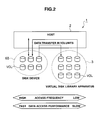
- Fig. 2 is a diagram illustrating access frequency and data access speed according to an embodiment.
- Fig. 3 is a diagram illustrating one of various tables.
- Fig. 4 is a diagram illustrating one of various tables.
- Fig. 5 is a diagram illustrating one of various tables.
- Fig. 6 is a flowchart showing a sequence in a processing procedure in the archive/backup system.
- Fig. 7 is a flowchart showing a sequence in a processing procedure in the archive/backup system.
- Fig. 8 is a flowchart showing a sequence in a processing procedure in the archive/backup system.
- Fig. 1 is a diagram illustrating the archive/backup system configuration according to the embodiment of the invention
- Fig. 2 is a diagram illustrating access frequency and data access speed in the archive/backup system according to the embodiment
- Figs. 3-5 are diagrams illustrating various tables
- Figs. 6-8 show sequences in processing procedures in the archive/backup system.
- an archive/backup system 1 includes a host computer 2 for processing data, a virtual disk library apparatus 3 that stores data from the host computer 2, and a management terminal 4.
- the host computer 2 is a computer device having information processing resources such as a CPU (Central Processing Unit) and memory, which are not shown in the figure, and examples of the host computer 2 include a personal computer, workstation, and mainframe.
- the host computer 2 has information input devices (not shown) such as a keyboard, switch, pointing device, and microphone, and information output devices (not shown) such as a monitor display and speaker.
- the CPU is a processor that governs operational control for the overall host computer 2.
- Memory is used for storing application program used during user operation, and also used as work memory for the CPU.
- Various types of processing relating to operations performed by the entire host computer 2 are executed by the CPU executing the application program stored in the memory.
- the host computer 2 transfers data in units of logical volumes VOL, which will be described later, between an external magnetic disk device 6B and a virtual disk library apparatus 3 (described later), each having a different data access speed, according to the frequency of access to archive/backup data recorded in the virtual disk library apparatus 3, data type, or importance of data i.e., data priority.
- the host computer 2 can transfer data according to data importance even if the archive/backup data has not been recorded in units of logical volumes VOL, or even if the head portion of the archive/backup data in the logical volume VOL is not transferred to the external magnetic disk device 6B.
- the virtual disk library apparatus 3 includes a magnetic disk device 6A and tape library device 7 that provide storage areas for storing data, and a controller (transfer controller) 5 for controlling data input/output to/from those devices.
- the virtual disk library apparatus 3 is used mainly for inexpensively maintaining a large volume of data that is not frequently accessed any more in a hierarchical storage system.
- the host computer 2 that manages the hierarchical storage system achieves inexpensive storage of a large volume of data by transferring data in units of logical volumes VOL between the magnetic disk devices with different data access performance according to data access frequency or necessity.
- the tape library device 7 is designed to record archive/backup data, and includes n (n being a natural number) magnetic tape(s) 14, a tape slot 15 for holding the magnetic tape(s) 14, and a tape drive 16 for reading/writing data recorded on the magnetic tape(s) 14.
- the magnetic disk device 6A includes disk devices (not shown).
- the disk devices are expensive disk drives such as SCSI (Small Computer System Interface) disks, or inexpensive disk drives such as SATA (Serial AT Attachment) disks or optical disks.
- VOL logical volume(s)
- logical blocks a predetermined size
- a specific identification number is provided to each logical device.
- data is input/output by specifying an address, which is a combination of the identification number and a specific number provided to each logical block (hereinafter referred to as an "LBA" (Logical Block Address)).
- LBA Logical Block Address
- the controller 5 includes a CPU (Central Processing Unit) 10, memory 12, and buffer 11 as shown in Fig. 1, and also, a first transfer unit, second transfer unit, timer, and calculator that are not shown in Fig. 1.
- the memory 12 is used for storing and maintaining various control programs and tables, and also used as work memory for the CPU 10.
- a volume status management table 20, disk storage information table 21, and tape storage information table 22, which will be described later, are also stored and maintained in the memory 12.
- the controller 5 executes various types of processing by having the CPU 10 execute the control programs stored in the memory 12.
- Each of the first and second transfer units, delay processor, timer, and calculator includes an IC (Integrated Circuit), CPU, ROM (Read Only Memory), and RAM (Random Access Memory), etc.
- the buffer 11 is designed to maintain arbitrary data.
- the arbitrary data may be the data identical to archive/backup data, or data different from archive/backup data, such as data used for buffering.
- the magnetic disk device 6A is used for temporarily caching data, and has a higher data access speed, if accessed from the controller 5, than that of the tape library device 7.
- the controller 5 transfers archive/backup data recorded on the tape library device 7 to the buffer 11, and also transfers archive/backup data held by the buffer 11 to the host computer 2.
- the first transfer unit (not shown) is used for transferring data from the tape library device 7 or magnetic disk device 6A to the buffer 11, and the second transfer unit is used for transferring data from the buffer 11 to the host computer 2.
- the controller 5 can transfer data bidirectionally between the tape library device 7 or magnetic disk device 6A and the host computer 2.
- the first and second transfer units may transfer data at the same time, or either the first or second transfer unit may transfer data after the other transfers the data.
- the delay processor delays the start of data transfer from the buffer 11 to the host computer 2 by a period of time shorter than the command response timeout time in the host computer 2, as will be described later.
- the delay processor includes a timer (measurer) (not shown) for measuring the elapsed time taken by the controller 5 to transfer archive/backup data recorded on the tape library device 7 to the buffer 11, and a calculator (not shown) for calculating the delay time by performing a difference calculation, i.e., subtracting the elapsed time measured by the timer from a preset adjustment time.
- the calculator may also finely adjust the delay time by, e.g., performing the difference calculation using a value obtained by multiplying the elapsed time by a fixed number according to the time taken for the magnetic tape 14 in the tape slot 15 to move to the tape drive 16, or the time taken to find the relevant spot on the magnetic tape 14.
- the controller 5 may also move the magnetic tape 14 to the position where archive/backup data has been recorded, based on the address contained in a data read request sent from the host computer 2, and read/write data from/to the magnetic tape 14.
- the buffer 11 may be provided inside the controller 5 as shown in Fig. 1, or may be provided outside the controller 5.
- the host computer 2 recognizes the virtual disk library apparatus 3 as plural logical volumes VOL virtualized (emulated) as virtual drives by the controller 5.
- the virtual disk library apparatus 3 includes virtual drive devices that record archive/backup data in units of logical volumes VOL, and the controller 5 transfers, in units of logical volumes VOL, the archive/backup data recorded in the virtual drive devices.
- the controller 5 also transfers archive/backup data recorded in units of logical volumes VOL to the magnetic disk device 6A.
- the controller 5 transfers the archive/backup data recorded on the head portion of a logical volume VOL configured in the tape library device 7 to the magnetic disk device 6A.
- the controller 5 makes archive/backup data reside in the magnetic disk device 6A having a higher data access speed than that of the tape library device 7.
- the management terminal 4 is a terminal device for maintaining and managing the virtual disk library apparatus 3.
- the management terminal 4 is a microcomputer system having information processing resources such as memory and CPU, not shown in the figures.
- the memory is used for maintaining various control programs and tables, and also used as work memory for the CPU.
- the management terminal 4 executes various types of processing by having the CPU execute the control programs stored in the memory.
- the feature of the archive/backup system 1 is a data write/read processing function with which command response timeout occurring until data transfer from the virtual disk library apparatus 3 to the host computer 2 starts can be prevented.
- the memory 12 in the controller 5 stores a volume status management table 20, disk storage information table 21, and tape storage information table 22.
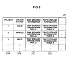
- the volume status management table 20 is a table for managing the status of each logical volume VOL in the virtual disk library apparatus 3, and contains, as shown in Fig. 3, a volume number field 20A, volume status field 20B, disk storage information field 20C, and tape storage information field 20D.
- the volume number field 20A stores a volume ID provided to a corresponding logical volume VOL.
- the volume status field 20B corresponding to each logical volume VOL to stores "valid” or “invalid” to indicate the logical volume VOL status, i.e., whether or not data in the relevant logical volume VOL is allocated to the magnetic disk device 6A or magnetic tape 14. "Valid” is stored if the data in the logical volume VOL is already allocated to an area in the magnetic disk device 6A or magnetic tape 14, and "invalid” is stored if the data is allocated to neither of them.
- the disk storage information field 20C stores the location of specific information for data in the magnetic disk device 6A.
- the tape storage information field 20D stores the location of specific information for data in the tape library device 7.
- the table shows "volume 1" to "volume 3" as the logical volume VOL number IDs.
- the volume status of the logical volume VOL with the ID of "volume 1" is "valid," data in the volume is already allocated to an area in the magnetic disk device 6A, and the specific information concerning the data in the magnetic disk device 6A and that in the tape library device 7 are stored respectively in table 1 in the later-described disk storage information table 21, and in table 1 in the later-described tape storage information table 22.
- the disk storage information table 21 is a table for managing specific information concerning the information stored in the magnetic disk device 6A. As shown in Fig. 4, the disk storage information table 21 contains a disk storage information table number field 21A, block 1 field 21 B, block 2 field 21C, and block 3 field 21 D.
- the disk storage information table number field 21A stores an ID provided to a relevant table number.
- Each of the block 1 field 21 B, block 2 field 21C, and block 3 field 21 D stores a disk ID to which information is allocated, an LBA from which information allocation is started, and data attribute information. However, if data has not been allocated to any area, "Area Not Allocated" is stored in the entries instead of the data attribute information.
- FIG. 4 shows that in the table with table number 1, information in block 1 is allocated to disk 1, data area allocation starts from LBA: 0A000000h in the logical block in disk 1, and the data attribute information is "resident." Being resident means that the data is maintained in the allocated magnetic disk device 6A.
- the table also shows that the information in block 2 is allocated to disk 2, data area allocation starts from LBA: 02000000h in the logical block in disk 2, and the data attribute information is "not resident (locked)." Being “not resident (locked)” means that the data is allocated to the magnetic disk device 6A but reuse of the relevant area is prevented.
- the tape storage information table 22 is a table for managing specific information concerning the information stored in the tape library device 7. As shown in Fig. 5, this tape storage information table 22A contains a tape storage information table number field 22A, table 1 field 22B, tape 2 field 22C, and tape 3 field 22D.
- the tape storage information table number field 22A stores an ID provided to a relevant table number.
- the tape 1 field 22B, tape 2 field 22C, and tape 3 field 22D respectively store the tape library and tape slot IDs to which the tape information is allocated. If the data area is not yet allocated, "invalid" is stored instead of the above information.
- Fig. 5 shows that in the table with table number 1, information on the tape 1 is allocated to the slot 10 in the tape library device 7 with tape library ID 1.
- the table also shows that any area is not yet allocated to information in the tapes 2 and 3, so the information is invalid.
- FIG. 6 and 7 are the flowcharts showing the data write processing sequences in the archive/backup system 1.
- Fig. 8 is a flowchart showing a data read processing sequenced in the archive/backup system 1.
- the host computer 2 when the host computer 2 starts data write to the virtual disk library apparatus 3 (SP1), the host computer 2 sends data to the buffer 11 in the controller 5 in the virtual disk library apparatus 3 (SP2).
- the virtual disk library apparatus 3 responds data write completion when finishing data transfer to the buffer 11.
- the CPU 10 in the controller 5 in the virtual disk library apparatus 3 refers to the disk storage information table 21 regarding the data written in units of logical volumes VOL (SP3) and checks whether or not the data is allocated to the magnetic disk device 6A.
- SP3 logical volumes VOL
- the CPU 10 allocates a disk area from unused or reusable disk areas in the magnetic disk device 6A to the data (SP7).
- the CPU 10 after finishing the allocation, updates information about the relevant logical volume VOL in the disk storage information table 21 (SP8).
- the CPU 10 writes the data from the buffer 11 to the magnetic disk device 6A (SP5), and ends the processing for data write to the magnetic disk device 6A (SP6).
- the CPU 10 writes the data transferred to the buffer 11 to the magnetic disk device 6A separately.
- the CPU 10 also orders that the data written to the magnetic disk device 6A be copied from the host computer 2 or the management terminal 4 to the magnetic tape 14 upon completion of data update to the logical volume VOL. That order triggers the virtual disk library apparatus 3 to start to copy the data in the logical volume VOL from the magnetic disk device 6A to the magnetic tape 14.
- the CPU 10 when data write to the tape library device 7 is started (SP10), the CPU 10 inhibits data write to the logical volume VOL (SP11).
- the CPU 10 also refers to the tape storage information table 22 regarding the logical volume VOL and moves the magnetic tape 14 the data in the logical volume VOL is to be stored on to the tape drive 16 (SP12).
- the CPU 10 copies the data in the logical volume VOL from the magnetic disk device 6A to the magnetic tape 14 (SP14).
- the CPU 10 after finishing the copy in step SP14, moves the magnetic tape 14 to the original tape slot 15 (SP15).
- the CPU 10 makes the head portion of the data reside, as a cache, in an area for the relevant logical volume VOL in the magnetic disk device 6A.
- the disk area for the logical volume VOL setting aside the disk areas storing the data to be resident, is made reusable, i.e., the disk area is released to make it available for recording data in other logical volumes VOL (SP16).
- the CPU 10 makes data write to the relevant logical volume VOL possible (SP17), and ends the data write processing (SP18).
- the value for the cache data transfer continuation time being the waiting time until the magnetic tape 14 is ready, is prepared in advance to match the tape library device 7 connected to the virtual disk library apparatus 3. For example, if the magnetic tape 14 ready-waiting cache data transfer continuation time is 5 minutes, the transfer speed limitation delay time is 10 seconds and the host computer 2 read request maximum data length per command is 256 KB, the cache capacity per volume is 7.5 MB.
- data can be transferred from the disk device 6A to the host computer 2 even until the host computer 2 becomes able to read data in the magnetic tape 14 by making in advance the head data of each logical volume VOL reside as a cache in a residence area in the magnetic disk device 6A. By doing so, command response timeout occurring in the host computer 2 while waiting for data transfer start from the magnetic tape 14 to the host computer 2 can be prevented.
- the CPU 10 cancels the data transfer speed limitation and transfers data to the host computer 2 at the maximum transfer speed.
- the host computer 2 sends, to the virtual disk library apparatus 3, a data read request containing information about a desired archive/backup data recorded portion.
- the CPU 10 in the controller 5 after receiving the data read request, starts the data read processing described below.
- the CPU 10 checks whether or not the magnetic tape 14 is ready (SP21). If the magnetic tape 14 is ready (SP21: YES) and data can be directly transferred from the magnetic tape 14 (SP32: YES), the CPU 10 transfers (moves or copies) data from the magnetic tape 14 to the buffer 11 at the maximum transfer speed (SP33).
- the CPU 10 refers to the disk storage information table 21 regarding the relevant logical volume VOL (SP34) and transfers data from the magnetic disk device 6A to the buffer 11 (SP35). After finishing step SP33 or SP35, the CPU 10 transfers the data held by the buffer 11 to the host computer 2 (SP30). The data read processing ends here (SP31).
- the CPU 10 refers to the tape storage information table 22 regarding the relevant logical volume VOL (SP23) and starts preparation for the magnetic tape 14 (SP24). Meanwhile, if the magnetic tape 14 is not yet ready in step SP21 (SP21: NO), the CPU 10 starts to measure the elapsed time (SP25).
- the CPU 10 refers to the disk storage information table 21 regarding the relevant volume VOL (SP26) and transfers data from the magnetic disk device 6A to the buffer 11 (SP27).
- the CPU 10 after finishing data transfer, ends the elapsed time measurement (SP28).
- the CPU 10 after receiving a command from the host computer 2, performs a difference calculation by subtracting the elapsed time from the transfer speed limitation delay time, and delays data transfer by the time (wait time) acquired by the difference calculation (SP29). By doing so, the data transfer speed is limited to be low.
- Transfer Speed Limitation Delay Time Host Command Response Timeout Time - Host Computer Read Request Maximum Data Length Per Command / Host Computer - Virtual Disk Library Device Maximum Transfer Speed ⁇ Transfer Margin Coefficient
- the transfer speed limitation delay time is set by subtracting, from the host command response timeout time, the time necessary for data transfer between the buffer 11 and the host computer 2.
- the time necessary for data transfer between the buffer 11 and the host computer 2 is set by dividing the host computer 2 read request maximum data length per command by the maximum transfer speed between the host computer 2 and the virtual disk library apparatus 3, then multiplying the result by the transfer margin coefficient.
- the transfer margin coefficient is a value used for adjustment for accurately measuring the transfer speed limitation delay time.
- the host command response timeout time, host computer 2 read request maximum data length per command, and transfer margin coefficient in the virtual disk library apparatus 3 can be changed from their default values from the management terminal 4 when necessary for each host computer 2.
- the maximum transfer speed (link speed, etc.) adjusted between the host computer 2 and the virtual disk library apparatus 3 is used as the host computer 2 - virtual disk library apparatus 3 maximum transfer speed.
- the transfer speed limitation delay time is 14 seconds.
- the CPU 10 transfers the data held by the buffer 11 to the host computer 2 (SP30), and the data read processing ends (SP31). Meanwhile, if data transfer from the magnetic disk device 6A to the buffer 11 did not end within the transfer speed limitation delay time, or if reading of the data in the magnetic tape 14 is not enabled even after transferring all data in the magnetic disk device 6A, the CPU 10 responds a status other than "normal" to the host computer 2.
- the controller 5 can continue data transfer, delaying data transfer to the host computer 2 at the magnetic disk device 6A in which the head data in the logical volume VOL is made to reside as a cache until reading of data in the magnetic tape 14 is enabled. Accordingly, the virtual disk library apparatus 3 can read data in all logical volume(s) VOL(s) without holding the cache capacity (several dozen TB) necessary when the controller 5 transfers data to the host computer 2, until reading of data in an arbitrary logical volume requested by the host computer 2 is enabled.
- the virtual disk library apparatus 3 stores several hundreds or several thousands of logical volumes VOL. Therefore, a huge capacity is necessary if data for enabling continuing data transfer is cached in the magnetic disk device 6A in the virtual disk library apparatus 3 until reading of data in the magnetic tape 14 for all logical volume VOL is enabled. Given a data transfer speed between the host computer 2 and the virtual disk library apparatus 3 of 100 MB/s, time for continuing data transfer at a cache of 5 minutes, and 1000 volumes in the virtual disk library apparatus, the necessary cache capacity can reach as much as 30 TB.
- the necessary cache capacity in the magnetic disk device 6A is about 10 GB. In this way, the above described cache capacity is greatly reduced.
- the time taken to transfer data between the buffer 11 and the host computer 2 is relatively short (several milliseconds to several dozen milliseconds), so the virtual disk library apparatus 3 can transfer data to the host computer 2 within the host computer 2 command response timeout time. More specifically, the CPU 10 waits for a shorter period of time than the host computer 2 command response timeout time before transferring data to the host computer 2, until reading of data in the magnetic tape 14 is enabled, thus limiting the data transfer speed to a low speed.
- the required cache capacity is about 10 GB.
- the virtual disk library apparatus 3 transfers archive/backup data recorded on the tape library device 7 to the buffer 11 (buffer transfer step), receives a data read request from the host computer 2 (read request reception step), delays start of data transfer from the buffer 11 to the host computer 2 by a shorter period of time than the host computer 2 command response timeout time (delay step), and transfers the transfer-delayed data to the buffer 11 (transfer step).
- the command response timeout occurring in the host computer until the virtual disk library apparatus 3 starts data transfer can be prevented without installing any application software dedicated for the virtual disk library apparatus 3 in the host computer 2.
- the virtual disk library apparatus 3 can continue the data transfer, limiting the effective data transfer speed to a low speed, while the magnetic disk device 6A is transferring data to the host computer 2.
- the delay processor in the controller 5 controls the transfer speed. Therefore, the controller 5 can reduce the cache capacity necessary for the virtual disk library apparatus 3 by limiting the data transfer speed.
- the storage apparatus, storage system, and data read method are not limited to the above described embodiment, and various modifications may of course be added without departing from the scope of the invention.
- archive/backup data is transferred.
- the invention is not limited to that and any data may be transferred.
- the buffer 11 is used as a device for storing data.
- the invention is not limited to that and various types of memory may be used instead of the buffer 11.
- the magnetic disk device 6, tape library device 7, and virtual disk library apparatus 3 are used as storage devices.
- the invention is not limited to that and other types of storage device may also be used.
- the invention can be applied widely to archive/backup systems having various configurations. According to the storage apparatus, storage system, and data read method in the invention, a large volume of data, the access frequency of which has been decreased, can be stored inexpensively in a hierarchical archive/backup system.
Landscapes
- Engineering & Computer Science (AREA)
- Theoretical Computer Science (AREA)
- Physics & Mathematics (AREA)
- General Engineering & Computer Science (AREA)
- General Physics & Mathematics (AREA)
- Human Computer Interaction (AREA)
- Library & Information Science (AREA)
- Information Retrieval, Db Structures And Fs Structures Therefor (AREA)
- Signal Processing For Digital Recording And Reproducing (AREA)
- Memory System Of A Hierarchy Structure (AREA)
Applications Claiming Priority (1)
| Application Number | Priority Date | Filing Date | Title |
|---|---|---|---|
| JP2006261246A JP2008083845A (ja) | 2006-09-26 | 2006-09-26 | ストレージ装置及びストレージシステム並びにデータ読出し方法 |
Publications (2)
| Publication Number | Publication Date |
|---|---|
| EP1909168A2 true EP1909168A2 (de) | 2008-04-09 |
| EP1909168A3 EP1909168A3 (de) | 2010-05-05 |
Family
ID=38823570
Family Applications (1)
| Application Number | Title | Priority Date | Filing Date |
|---|---|---|---|
| EP07253385A Withdrawn EP1909168A3 (de) | 2006-09-26 | 2007-08-28 | Speichervorrichtung, Speichersystem und Datenlesevorrichtung |
Country Status (3)
| Country | Link |
|---|---|
| US (1) | US20080077739A1 (de) |
| EP (1) | EP1909168A3 (de) |
| JP (1) | JP2008083845A (de) |
Families Citing this family (13)
| Publication number | Priority date | Publication date | Assignee | Title |
|---|---|---|---|---|
| GB0614515D0 (en) | 2006-07-21 | 2006-08-30 | Ibm | An apparatus for managing power-consumption |
| JP4923008B2 (ja) * | 2008-08-22 | 2012-04-25 | 株式会社日立製作所 | ストレージ管理装置、ストレージ管理方法およびストレージ管理プログラム |
| US8713277B2 (en) * | 2010-06-01 | 2014-04-29 | Apple Inc. | Critical word forwarding with adaptive prediction |
| US9563365B2 (en) | 2012-04-30 | 2017-02-07 | Kip Cr P1 Lp | System and method for using a memory buffer to stream data from a tape to multiple clients |
| US8977827B1 (en) | 2012-05-31 | 2015-03-10 | Kip Cr P1 Lp | System, method and computer program product for recovering stub files |
| JP6186787B2 (ja) * | 2013-03-25 | 2017-08-30 | 富士通株式会社 | データ転送装置、データ転送システム、データ転送方法及びプログラム |
| JP6089856B2 (ja) * | 2013-03-26 | 2017-03-08 | 富士通株式会社 | 仮想テープ装置、テープ制御装置、およびテープ制御方法 |
| US9971796B2 (en) * | 2013-04-25 | 2018-05-15 | Amazon Technologies, Inc. | Object storage using multiple dimensions of object information |
| JP2015022345A (ja) * | 2013-07-16 | 2015-02-02 | インターナショナル・ビジネス・マシーンズ・コーポレーションInternational Business Machines Corporation | データ転送が停止しまうことがないように、キャッシュされているデータの転送レートを適合させる方法、システム、および、プログラム |
| US10423336B2 (en) * | 2017-11-28 | 2019-09-24 | International Business Machines Corporation | Fast locate using imitation reads on tape drives |
| JP7323769B2 (ja) * | 2019-04-15 | 2023-08-09 | 富士通株式会社 | ストレージ装置、ストレージシステムおよびプログラム |
| JP7409196B2 (ja) * | 2020-03-27 | 2024-01-09 | 富士通株式会社 | ストレージ制御装置、ストレージシステム、及びストレージ制御プログラム |
| US20220260379A1 (en) * | 2021-05-07 | 2022-08-18 | Atlis Motor Vehicles, Inc. | Methods and Apparatus for Determining a Likelihood of Successful Transmission of Data from a Mobile Vehicle |
Family Cites Families (6)
| Publication number | Priority date | Publication date | Assignee | Title |
|---|---|---|---|---|
| JPH08195022A (ja) * | 1994-11-14 | 1996-07-30 | Sega Enterp Ltd | ディスク再生装置、カラオケシステム及びディスク再生方法 |
| JP3140384B2 (ja) * | 1995-12-01 | 2001-03-05 | エル エス アイ ロジック コーポレーション | ビデオ伝送方法及びデータ処理システム |
| US6173359B1 (en) * | 1997-08-27 | 2001-01-09 | International Business Machines Corp. | Storage and access to scratch mounts in VTS system |
| EP1182875A3 (de) * | 2000-07-06 | 2003-11-26 | Matsushita Electric Industrial Co., Ltd. | Strömungsverfahren und entsprechendes System |
| JP3778055B2 (ja) * | 2001-11-02 | 2006-05-24 | ソニー株式会社 | 記録再生装置及び記録再生方法 |
| JP4322068B2 (ja) * | 2003-03-07 | 2009-08-26 | 富士通株式会社 | ストレージシステム及びそのデイスク負荷バランス制御方法 |
-
2006
- 2006-09-26 JP JP2006261246A patent/JP2008083845A/ja active Pending
-
2007
- 2007-02-07 US US11/703,164 patent/US20080077739A1/en not_active Abandoned
- 2007-08-28 EP EP07253385A patent/EP1909168A3/de not_active Withdrawn
Non-Patent Citations (1)
| Title |
|---|
| None |
Also Published As
| Publication number | Publication date |
|---|---|
| JP2008083845A (ja) | 2008-04-10 |
| US20080077739A1 (en) | 2008-03-27 |
| EP1909168A3 (de) | 2010-05-05 |
Similar Documents
| Publication | Publication Date | Title |
|---|---|---|
| EP1909168A2 (de) | Speichervorrichtung, Speichersystem und Datenlesevorrichtung | |
| KR100962883B1 (ko) | 소스 데이터를 타겟 데이터로 이전하는 방법, 시스템 및제조물 | |
| US8375167B2 (en) | Storage system, control apparatus and method of controlling control apparatus | |
| US8001345B2 (en) | Automatic triggering of backing store re-initialization | |
| US9563636B2 (en) | Allowing writes to complete without obtaining a write lock to a file | |
| US8271444B2 (en) | Storage control device to backup data stored in virtual volume | |
| US7783603B2 (en) | Backing store re-initialization method and apparatus | |
| US6665743B2 (en) | Method, system, and program for initializing a storage space | |
| US8949536B2 (en) | Prefetching source tracks for destaging updated tracks in a copy relationship | |
| JP4681247B2 (ja) | ディスクアレイ装置及びディスクアレイ装置の制御方法 | |
| JP5090072B2 (ja) | 第1記憶場所から第2記憶場所に論理ボリュームを再配置するための方法、コンピュータ・システム、及びプログラム | |
| US20050262296A1 (en) | Selective dual copy control of data storage and copying in a peer-to-peer virtual tape server system | |
| JP2005011317A (ja) | ストレージシステムを初期化する方法と装置 | |
| US7523253B2 (en) | Storage system comprising a plurality of tape media one of which corresponding to a virtual disk | |
| EP1736860A1 (de) | Speichersteuerung und Steuerverfahren dafür | |
| JP2012014286A (ja) | ストレージシステム、同システムにおけるデータバックアップ方法及びデータバックアッププログラム | |
| US20120216009A1 (en) | Source-target relations mapping | |
| US20150347033A1 (en) | Storage controlling device, storage controlling method, storage system and program | |
| US20140331007A1 (en) | Virtual library controller and control method | |
| US9513804B2 (en) | Virtual tape device and virtual tape device control method | |
| WO2013160939A1 (en) | Backup system and backup method | |
| US7254672B1 (en) | Translation device driver for translating between disk device driver and tape device driver commands | |
| US20140289485A1 (en) | Storage system, control apparatus, and method for controlling storage system | |
| US20060277353A1 (en) | Virtual tape library device, virtual tape library system, and method for writing data to a virtual tape | |
| US9740434B2 (en) | Storage device and control method |
Legal Events
| Date | Code | Title | Description |
|---|---|---|---|
| PUAI | Public reference made under article 153(3) epc to a published international application that has entered the european phase |
Free format text: ORIGINAL CODE: 0009012 |
|
| 17P | Request for examination filed |
Effective date: 20070917 |
|
| AK | Designated contracting states |
Kind code of ref document: A2 Designated state(s): AT BE BG CH CY CZ DE DK EE ES FI FR GB GR HU IE IS IT LI LT LU LV MC MT NL PL PT RO SE SI SK TR |
|
| AX | Request for extension of the european patent |
Extension state: AL BA HR MK RS |
|
| PUAL | Search report despatched |
Free format text: ORIGINAL CODE: 0009013 |
|
| AK | Designated contracting states |
Kind code of ref document: A3 Designated state(s): AT BE BG CH CY CZ DE DK EE ES FI FR GB GR HU IE IS IT LI LT LU LV MC MT NL PL PT RO SE SI SK TR |
|
| AX | Request for extension of the european patent |
Extension state: AL BA HR MK RS |
|
| AKX | Designation fees paid |
Designated state(s): DE FR GB IE |
|
| 17Q | First examination report despatched |
Effective date: 20130821 |
|
| STAA | Information on the status of an ep patent application or granted ep patent |
Free format text: STATUS: THE APPLICATION IS DEEMED TO BE WITHDRAWN |
|
| 18D | Application deemed to be withdrawn |
Effective date: 20140103 |