EP1908984A2 - Amortisseur d'oscillations doté d'une force d'amortissement à amplitude sélective - Google Patents
Amortisseur d'oscillations doté d'une force d'amortissement à amplitude sélective Download PDFInfo
- Publication number
- EP1908984A2 EP1908984A2 EP07018759A EP07018759A EP1908984A2 EP 1908984 A2 EP1908984 A2 EP 1908984A2 EP 07018759 A EP07018759 A EP 07018759A EP 07018759 A EP07018759 A EP 07018759A EP 1908984 A2 EP1908984 A2 EP 1908984A2
- Authority
- EP
- European Patent Office
- Prior art keywords
- piston rod
- valve
- vibration damper
- damper according
- valve sleeve
- Prior art date
- Legal status (The legal status is an assumption and is not a legal conclusion. Google has not performed a legal analysis and makes no representation as to the accuracy of the status listed.)
- Withdrawn
Links
- 238000013016 damping Methods 0.000 title claims abstract description 17
- 238000007789 sealing Methods 0.000 claims description 7
- 238000010276 construction Methods 0.000 description 1
- 230000001419 dependent effect Effects 0.000 description 1
- 230000036316 preload Effects 0.000 description 1
Images
Classifications
-
- F—MECHANICAL ENGINEERING; LIGHTING; HEATING; WEAPONS; BLASTING
- F16—ENGINEERING ELEMENTS AND UNITS; GENERAL MEASURES FOR PRODUCING AND MAINTAINING EFFECTIVE FUNCTIONING OF MACHINES OR INSTALLATIONS; THERMAL INSULATION IN GENERAL
- F16F—SPRINGS; SHOCK-ABSORBERS; MEANS FOR DAMPING VIBRATION
- F16F9/00—Springs, vibration-dampers, shock-absorbers, or similarly-constructed movement-dampers using a fluid or the equivalent as damping medium
- F16F9/32—Details
- F16F9/48—Arrangements for providing different damping effects at different parts of the stroke
Definitions
- the invention enters a vibration damper with amplitude-selective damping force according to the preamble of patent claim 1.
- a hydraulic vibration damper with a piston rod which is guided axially movable together with a piston in a cylinder.
- the piston divides the cylinder into a piston rod side and a piston rod remote working space, both of which are filled with a damping medium.
- a valve ring is slidably disposed on the piston rod, which drives by its axial position a valve opening in its cross section.
- the valve ring is in frictional contact with the piston rod, so that the valve ring executes an axial movement during a stroke movement of the piston rod while the damping volume can flow out of the piston rod side working space until the valve ring closes the valve opening after a defined stroke.
- the DE 39 14 298 C1 describes a principle solution.
- the object of the present invention is to provide a production-ready construction.
- the object is achieved in that a valve sleeve is arranged in the piston rod side working space in which the valve ring is guided axially movable.
- the great advantage is that all the function of the amplitude-selective damping force-determining components are arranged within the valve sleeve and this unit is inserted into the cylinder, so that no costly changes to the cylinder are necessary. This unit could be checked on a test bench independently of the vibration damper.
- valve sleeve is supported at least indirectly on a piston rod guide axially terminating the cylinder. Furthermore, it is provided that the valve sleeve has a bottom with a passage opening for the piston rod, wherein the bottom has at least one connection opening which can be closed by an end face of the valve ring.
- valve opening In the structural design of the valve opening different options are available. First, you can run the valve opening in the cylinder.
- valve opening is carried out in the piston rod guide.
- the valve opening in the piston rod guide is formed by an end-side groove extending through an axial stop surface for the cylinder.
- the preparation of the valve opening can be made in a piston rod made of a sintered material very simple and practically cost-neutral in particular.
- valve sleeve determines an axial channel
- the damping medium can flow in a limited of the valve sleeve working chamber between the valve ring and the piston rod guide.
- the axial channel is formed by an at least partial outer diameter reduction of the valve sleeve. You can reduce the outer diameter fully or provide at least one groove.
- valve sleeve is sealed to the inner wall of the cylinder by means of at least one seal.
- the radial preload of the seal is selected such that the axial position of the valve sleeve is secured via the seal.
- the valve sleeve has at least one flow connection between two sections of the working chamber divided by the valve ring, determined by the piston rod and the inner wall of the valve sleeve.
- the valve ring should be actuated as far as possible free of compressive forces in the working chambers purely path-dependent of the piston rod.
- the flow connection is formed by a longitudinal groove in the inner wall of the valve sleeve, so that the valve ring can have a uniform circular shape.
- the valve ring comprises a friction ring and a sealing ring which is radially movable relative to the friction ring and influences the inflow into the valve opening.
- the sealing ring surrounds the friction ring on the outside and comprises a shell portion and a bottom, wherein the friction ring is supported on the inside on the ground.
- valve ring Another measure for pressure equalization on the valve ring is that the working chamber between the valve ring and a cover of the valve sleeve has a throttle opening to the piston rod side working space. When a piston rod movement of the valve ring is acted upon on both sides with damping medium.
- the throttle opening is formed by the cover in conjunction with a throttle disc clamped to the valve sleeve. By replacing the throttle disk, the distribution of the damping medium volume flowing into the working chambers can be adjusted.
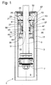
- a vibration damper 1 shows a section of a vibration damper 1, which has a cylinder 3, in which a piston rod 5 is mounted with a piston 7 axially movable.
- the piston 7 divides the cylinder 3 in a piston rod remote and a piston rod side working space 9; 11, wherein a piston rod guide 13 closes the piston rod side working chamber 11 of the cylinder 3.
- the cylinder 3 is enclosed by a container tube 15, whereby a compensation space 17 determined thereby compensates the volume of the retracting and extending piston rod 5.
- a valve sleeve 19 is arranged, the bottom 21 rests indirectly via a throttle plate 23 at a facing in the direction of the working space 11 end face 25 of the piston rod guide 13.
- a valve ring 27 is axially slidably mounted on the lateral surface of the piston rod 5, so that within the valve sleeve two working chambers 29; 31 present.
- the z. B. is formed by a longitudinal groove in the inner wall of the valve sleeve 13.
- the valve sleeve 19 is guided radially from the inner wall of the cylinder 3.
- An outer diameter reduction in the form of at least one axial groove 35 forms an axial passage between the piston rod side working space 11 and the present between the valve ring 27 and the bottom 21 working chamber 29 within the valve sleeve 19, wherein between the axial passage 35 and the working chamber 29 at least one connecting channel 37 is , It is also possible to have a plurality of axial channels.
- the working chamber 31 delimited by a cover 39 of the valve sleeve 19 and the valve ring 27 has a throttle opening 41 for the piston rod side Working space 11 on.
- the throttle opening 41 is formed by at least one throttle disk 43 arranged between the cover and the valve sleeve.
- the valve ring 27 has a friction ring 45 sliding on the piston rod and a sealing ring 47 enclosing the friction ring on the outside with a lateral surface, wherein the sealing ring 47 can move radially within limits of the friction ring 45.
- the friction ring 45 can be axially supported on a bottom 49 of the sealing ring 47 and a retaining ring 51.
- a valve opening 53 is executed in the cylinder, which via the Vorö Stammsectomy 23 and a connection channel 55 in the bottom 21 of the valve sleeve 19 to the working chambers 29; 31 of the valve sleeve 19 is connected.
- the connection channel 55 is formed by a passage opening 57 in the bottom, through which the piston rod 5 extends, wherein the valve ring 27 closes the passage opening 57 with its upper end face 59.
- valve ring 27 comes to bear against the inside of the bottom 21 of the valve sleeve 19 and seals the connection channel 55 to the valve opening 53 and the connection channel 37.
- the axial passage 35 between the cylinder wall and the valve sleeve is closed by a seal 61 at the end, so that the damping medium located there can not continue to flow.
- the seal 61 also serves to axially fix the valve sleeve 19 within the cylinder 3. From this Hublage the damping force of damping valves, z. B. in the piston 7, determined.
- the volume in the working chambers 29; 31 of the valve sleeve 19 is compressed in the piston rod extension movement via the throttle opening 41, so that an additional hydraulic closing force acts on the valve ring 27.
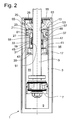
- valve opening 53 is formed by an end-side groove 63 within the piston rod guide 13 which extends through an axial stop surface 65 for the cylinder and thus flow around the end face leaves.
Landscapes
- Engineering & Computer Science (AREA)
- General Engineering & Computer Science (AREA)
- Mechanical Engineering (AREA)
- Fluid-Damping Devices (AREA)
Applications Claiming Priority (1)
| Application Number | Priority Date | Filing Date | Title |
|---|---|---|---|
| DE102006047093A DE102006047093A1 (de) | 2006-10-05 | 2006-10-05 | Schwingungsdämpfer mit amplitudenselektiver Dämpfkraft |
Publications (2)
| Publication Number | Publication Date |
|---|---|
| EP1908984A2 true EP1908984A2 (fr) | 2008-04-09 |
| EP1908984A3 EP1908984A3 (fr) | 2010-04-28 |
Family
ID=38950844
Family Applications (1)
| Application Number | Title | Priority Date | Filing Date |
|---|---|---|---|
| EP07018759A Withdrawn EP1908984A3 (fr) | 2006-10-05 | 2007-09-25 | Amortisseur d'oscillations doté d'une force d'amortissement à amplitude sélective |
Country Status (3)
| Country | Link |
|---|---|
| US (1) | US20080115663A1 (fr) |
| EP (1) | EP1908984A3 (fr) |
| DE (1) | DE102006047093A1 (fr) |
Cited By (1)
| Publication number | Priority date | Publication date | Assignee | Title |
|---|---|---|---|---|
| EP2175160A3 (fr) * | 2008-10-07 | 2014-06-25 | ZF Friedrichshafen AG | Amortisseur d'oscillations doté d'une force d'amortissement à amplitude sélective |
Families Citing this family (4)
| Publication number | Priority date | Publication date | Assignee | Title |
|---|---|---|---|---|
| DE102008014543B3 (de) * | 2008-03-15 | 2009-06-25 | Zf Friedrichshafen Ag | Schwingungsdämpfer mit amplitudenselektiver Dämpfkraft |
| DE102010029180A1 (de) * | 2010-05-20 | 2011-11-24 | Suspa Gmbh | Dämpfer |
| DE102011086247B3 (de) * | 2011-11-14 | 2013-02-07 | Zf Friedrichshafen Ag | Schwingungsdämpfer |
| JP6324254B2 (ja) * | 2014-07-31 | 2018-05-16 | 日立オートモティブシステムズ株式会社 | 緩衝器付き車両 |
Citations (1)
| Publication number | Priority date | Publication date | Assignee | Title |
|---|---|---|---|---|
| DE3914298C1 (en) | 1989-04-29 | 1990-08-30 | Boge Ag, 5208 Eitorf, De | Hydraulic oscillation damper with fluid ram - has axially slidable control disc, guided sealingly on piston rod in ram cylinder |
Family Cites Families (11)
| Publication number | Priority date | Publication date | Assignee | Title |
|---|---|---|---|---|
| GB714180A (en) * | 1951-12-10 | 1954-08-25 | George Herbert Shepherd | Improvements in or relating to hydraulic dampers |
| DE1430564A1 (de) * | 1963-10-04 | 1968-12-05 | Bosch Gmbh Robert | Fluessigkeitsstossdaempfer fuer Kraftfahrzeuge |
| DE2922437A1 (de) * | 1979-06-01 | 1980-12-11 | Fichtel & Sachs Ag | Zweirohrschwingungsdaempfer mit universell anwendbarer kolbenstangenfuehrung |
| DE3128723A1 (de) * | 1981-07-21 | 1983-02-10 | Fichtel & Sachs Ag, 8720 Schweinfurt | Hydropneumatischer zweirohr-schwingungsdaempfer oder federbeineinsatz mit einer verschlusskappe fuer ein behaelterrohr |
| US5509512A (en) * | 1993-02-17 | 1996-04-23 | Fichtel & Sachs Ag | Shock absorber with adjustable damping with controlled damping characteristics |
| US6352145B1 (en) * | 1998-10-07 | 2002-03-05 | Tenneco Automotive Inc. | Stroke dependent damping |
| US7216747B2 (en) * | 2004-10-14 | 2007-05-15 | Tenneco Automotive Operating Company Inc. | Amplitude controlled orifice valving |
| US7431135B2 (en) * | 2004-10-27 | 2008-10-07 | Tenneco Automotive Operating Company Inc. | Stroke dependent damping |
| DE102004058965B4 (de) * | 2004-12-08 | 2010-07-08 | Zf Friedrichshafen Ag | Schwingungsdämpfer mit amplitudenselektiver Dämpfkraft |
| DE102005020293A1 (de) * | 2005-04-30 | 2006-11-09 | Zf Friedrichshafen Ag | Schwingungsdämpfer mit amplitudenselektiver Dämpfkraft |
| DE102006008675B3 (de) * | 2006-02-24 | 2007-09-13 | Zf Friedrichshafen Ag | Schwingungsdämpfer mit amplitudenselektiver Dämpfkraft |
-
2006
- 2006-10-05 DE DE102006047093A patent/DE102006047093A1/de not_active Ceased
-
2007
- 2007-09-25 EP EP07018759A patent/EP1908984A3/fr not_active Withdrawn
- 2007-10-04 US US11/906,841 patent/US20080115663A1/en not_active Abandoned
Patent Citations (1)
| Publication number | Priority date | Publication date | Assignee | Title |
|---|---|---|---|---|
| DE3914298C1 (en) | 1989-04-29 | 1990-08-30 | Boge Ag, 5208 Eitorf, De | Hydraulic oscillation damper with fluid ram - has axially slidable control disc, guided sealingly on piston rod in ram cylinder |
Cited By (1)
| Publication number | Priority date | Publication date | Assignee | Title |
|---|---|---|---|---|
| EP2175160A3 (fr) * | 2008-10-07 | 2014-06-25 | ZF Friedrichshafen AG | Amortisseur d'oscillations doté d'une force d'amortissement à amplitude sélective |
Also Published As
| Publication number | Publication date |
|---|---|
| EP1908984A3 (fr) | 2010-04-28 |
| DE102006047093A1 (de) | 2008-04-10 |
| US20080115663A1 (en) | 2008-05-22 |
Similar Documents
| Publication | Publication Date | Title |
|---|---|---|
| DE102013112818B4 (de) | Federelement | |
| DE102010000574B4 (de) | Gasfeder mit verzögerter Rückstellung | |
| DE102014004667A1 (de) | Ventil | |
| DE102009061003A1 (de) | Verstellbare Dämpfventileinrichtung | |
| EP1953410A1 (fr) | Amortisseur d'oscillations hydraulique | |
| EP2075398A2 (fr) | Entraînement pour un battant d'une fenêtre ou d'une porte | |
| EP1923595B1 (fr) | Amortisseur d'oscillations doté d'une force d'amortissement dépendant de l'amplitude | |
| DE102008042103A1 (de) | Schwingungsdämpfer mit amplitudenselektiver Dämpfkraft | |
| EP1908984A2 (fr) | Amortisseur d'oscillations doté d'une force d'amortissement à amplitude sélective | |
| DE102004039702A1 (de) | Selbstpumpendes hydropneumatisches Federbein | |
| DE102005053394A1 (de) | Schwingungsdämpfer mit verstellbarer Dämpfkraft | |
| DE102005061164B4 (de) | Schwingungsdämpfer mit einer Anschlagfeder | |
| EP1998070A2 (fr) | Amortisseur de vibrations, en particulier amortisseurs de direction | |
| DE102008040643B3 (de) | Schwingungsdämpfer mit amplitudenabhängiger Dämpfkraft | |
| DE102007027813B4 (de) | Schwingungsdämpfer mit verstellbarem Dämpfventil | |
| DE102016224353A1 (de) | Hydraulischer Endanschlag für einen Schwingungsdämpfer | |
| DE102009010170A1 (de) | Sattelstütze | |
| DE102012215614A1 (de) | Schwingungsdämpfer mit einer beschleunigungsabhängigen Dämpfeinrichtung | |
| EP3037679B1 (fr) | Actionneur fluidique | |
| DE102008042634B4 (de) | Schwingungsdämpfer mit amplitudenselektiver Dämpfkraft | |
| DE102008042637B4 (de) | Ventileinrichtung mit amplitudenabhängiger Dämpfkraft | |
| DE10158123B4 (de) | Endlagengedämpfter Druckmittelzylinder | |
| EP2103836A3 (fr) | Amortisseur d'oscillations doté d'une force d'amortissement à amplitude sélective | |
| DE102008044081A1 (de) | Schwingungsdämpfer mit hubabhängiger Dämpfkraft | |
| DE102010031144B4 (de) | Schwingungsdämpfer mit amplitudenabhängiger Dämpfkraft |
Legal Events
| Date | Code | Title | Description |
|---|---|---|---|
| PUAI | Public reference made under article 153(3) epc to a published international application that has entered the european phase |
Free format text: ORIGINAL CODE: 0009012 |
|
| AK | Designated contracting states |
Kind code of ref document: A2 Designated state(s): AT BE BG CH CY CZ DE DK EE ES FI FR GB GR HU IE IS IT LI LT LU LV MC MT NL PL PT RO SE SI SK TR |
|
| AX | Request for extension of the european patent |
Extension state: AL BA HR MK RS |
|
| PUAL | Search report despatched |
Free format text: ORIGINAL CODE: 0009013 |
|
| AK | Designated contracting states |
Kind code of ref document: A3 Designated state(s): AT BE BG CH CY CZ DE DK EE ES FI FR GB GR HU IE IS IT LI LT LU LV MC MT NL PL PT RO SE SI SK TR |
|
| AX | Request for extension of the european patent |
Extension state: AL BA HR MK RS |
|
| 17P | Request for examination filed |
Effective date: 20101022 |
|
| 17Q | First examination report despatched |
Effective date: 20101124 |
|
| AKX | Designation fees paid |
Designated state(s): AT BE BG CH CY CZ DE DK EE ES FI FR GB GR HU IE IS IT LI LT LU LV MC MT NL PL PT RO SE SI SK TR |
|
| GRAP | Despatch of communication of intention to grant a patent |
Free format text: ORIGINAL CODE: EPIDOSNIGR1 |
|
| INTG | Intention to grant announced |
Effective date: 20141205 |
|
| STAA | Information on the status of an ep patent application or granted ep patent |
Free format text: STATUS: THE APPLICATION IS DEEMED TO BE WITHDRAWN |
|
| 18D | Application deemed to be withdrawn |
Effective date: 20150416 |