EP1908978A2 - Dispositif de couplage pour un véhicule - Google Patents
Dispositif de couplage pour un véhicule Download PDFInfo
- Publication number
- EP1908978A2 EP1908978A2 EP07018772A EP07018772A EP1908978A2 EP 1908978 A2 EP1908978 A2 EP 1908978A2 EP 07018772 A EP07018772 A EP 07018772A EP 07018772 A EP07018772 A EP 07018772A EP 1908978 A2 EP1908978 A2 EP 1908978A2
- Authority
- EP
- European Patent Office
- Prior art keywords
- friction
- friction elements
- group
- arrangement
- elements
- Prior art date
- Legal status (The legal status is an assumption and is not a legal conclusion. Google has not performed a legal analysis and makes no representation as to the accuracy of the status listed.)
- Withdrawn
Links
Images

Classifications
-
- F—MECHANICAL ENGINEERING; LIGHTING; HEATING; WEAPONS; BLASTING
- F16—ENGINEERING ELEMENTS AND UNITS; GENERAL MEASURES FOR PRODUCING AND MAINTAINING EFFECTIVE FUNCTIONING OF MACHINES OR INSTALLATIONS; THERMAL INSULATION IN GENERAL
- F16D—COUPLINGS FOR TRANSMITTING ROTATION; CLUTCHES; BRAKES
- F16D25/00—Fluid-actuated clutches
- F16D25/06—Fluid-actuated clutches in which the fluid actuates a piston incorporated in, i.e. rotating with the clutch
- F16D25/062—Fluid-actuated clutches in which the fluid actuates a piston incorporated in, i.e. rotating with the clutch the clutch having friction surfaces
- F16D25/063—Fluid-actuated clutches in which the fluid actuates a piston incorporated in, i.e. rotating with the clutch the clutch having friction surfaces with clutch members exclusively moving axially
- F16D25/0635—Fluid-actuated clutches in which the fluid actuates a piston incorporated in, i.e. rotating with the clutch the clutch having friction surfaces with clutch members exclusively moving axially with flat friction surfaces, e.g. discs
- F16D25/0638—Fluid-actuated clutches in which the fluid actuates a piston incorporated in, i.e. rotating with the clutch the clutch having friction surfaces with clutch members exclusively moving axially with flat friction surfaces, e.g. discs with more than two discs, e.g. multiple lamellae
-
- F—MECHANICAL ENGINEERING; LIGHTING; HEATING; WEAPONS; BLASTING
- F16—ENGINEERING ELEMENTS AND UNITS; GENERAL MEASURES FOR PRODUCING AND MAINTAINING EFFECTIVE FUNCTIONING OF MACHINES OR INSTALLATIONS; THERMAL INSULATION IN GENERAL
- F16D—COUPLINGS FOR TRANSMITTING ROTATION; CLUTCHES; BRAKES
- F16D25/00—Fluid-actuated clutches
- F16D25/12—Details not specific to one of the before-mentioned types
Definitions
- the present invention relates to a clutch assembly for a vehicle comprising a housing assembly to be connected to a drive member for rotation about an axis of rotation and filled or filled with fluid, a first group of friction elements coupled to the housing assembly for rotation about the axis of rotation via a first friction member carrier a second piston element, by means of which the friction elements of the first group of friction elements and the friction elements of the second group of friction elements can be brought into frictional engagement via a second friction element carrier with a driven member for rotation about the axis of rotation, wherein on the first friction element carrier or on second friction element support an abutment arrangement is provided for generating a supporting action for the acted upon by the piston element friction elements.
- This spring element which generates no or no significant engagement force transmitting interaction between the piston element and the friction element acted upon by this, leads to the problem that due to its ring-like closed configuration the fürströmhus of the various friction elements containing housing assembly is impaired and thus can cause problems in the to be achieved by fluid circulation cooling the friction elements.
- a clutch arrangement for a vehicle comprising a housing arrangement to be connected to a drive member for rotation about a rotation axis and filled or filled with fluid, a first group of friction elements coupled to the housing arrangement for rotation about the axis of rotation via a first friction element carrier a second group of friction elements to be coupled via a second friction element support with a driven member for rotation about the rotation axis, a piston member by which the friction elements of the first group of friction elements and the friction elements of the second group of friction elements are frictionally engaged, wherein on the first Reibelementenarme or on the second Reibelementenlement an abutment arrangement is provided for generating a supporting action for the acted upon by the piston member friction elements, wherein in the force path between the piston member and the abutment arrangement an elastic Arrangement is provided which is axially compressible when the friction elements are acted upon by the piston element.
- the elastic arrangement may comprise at least one plate-like shielded friction element of the first group of friction elements and / or the second group of friction elements.
- all friction elements of the first group of friction elements or all friction elements of the second group of friction elements are shielded like a plate.
- the elastic action of a plurality of friction elements can be combined, so that each individual plate-like shielded friction element must be shielded comparatively low and nevertheless a comparatively large axial elasticity can be integrated into the groups of friction elements by the sum of the individual elasticities ,
- the friction elements of the first group of friction elements or the friction elements of the second group of friction elements have friction linings on both axial sides and that the at least one plate-like shielded friction element is a friction element with friction linings.
- the abutment arrangement may comprise an axial elastic ring element supported by an axial securing element with respect to a friction element carrier and axially supporting the friction elements, which then forms at least part of the elastic arrangement.
- a friction element of the first group of friction elements or the second group of friction elements comprises two disc parts, wherein a first of the disc parts is substantially planar and provides a friction surface and a second the disc parts is formed plate-like shielded and is axially supported via an axial securing element with respect to a Reibelementenarmes and forms at least part of the elastic arrangement.
- the piston element can act on the friction elements via a wave-like design, axially elastic ring element, which then forms at least part of the elastic arrangement.
- This ring element can be substantially non-rotatable with a friction element carrier with which a friction element which is also in contact with this ring element is substantially non-rotatable.
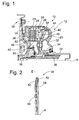
- a generally designated 10 clutch assembly is shown.
- This comprises a housing assembly 12 with a motor-side housing shell 14, which via a coupling arrangement 16 with a drive member effective crankshaft or the like is rotatably coupled.
- Radially inside the motor-side housing shell 14 is fixedly connected to a housing hub 18, for example by welding.
- This housing hub 18 can be radially supported on the drive member.
- the housing assembly 12 further includes a transmission-side housing shell 20 which is fixedly connected radially externally to the motor-side housing shell 14 by welding and which is fixed radially inwardly with a drive hub 22 by welding, which engages in the assembled state of a drive train in a transmission and there Can drive fluid pump.
- the housing shell 14 forms with its radially outer region a first friction element carrier 24, with which friction elements 26 of a first group 28 are rotatably coupled by friction elements by Veryakungsartigen engagement, with respect to this, however, are axially displaceable.
- a second Reibelementenarme 30 is coupled via a Torsionsschwingungsdämpferantechnischigan 32 with an output hub 34, which in turn with a driven member 36, that is, for example, a transmission input shaft, rotatably by toothing engagement.
- Friction elements 38 of a second group 40 of friction elements are rotatably connected by toothing engagement with the second Reibelementenexcellent 30, with respect to this, however, connected axially displaceable. It can be seen that, in this arrangement, a respective friction element 26 of the first group 28 of friction elements and a friction element 38 of the second group 40 of friction elements alternate with each other.
- a with respect to the housing assembly 12 supported and axially displaceable piston member 42 can press axially in its radially outer region with axial displacement of the friction elements 26 and 38 against each other, wherein an abutment assembly 44 generates a reaction force support.
- This abutment arrangement 44 comprises a securing ring 46, which is fixed to the first housing 14 or to the first friction element carrier 24 and to which a friction element 26 of the first group 28 of FIG Friction elements effective disc member 48 is axially supported.
- the friction elements 26 of the first group 28 are constructed of friction elements as substantially planar-shaped disk parts, for example made of sheet metal material.
- the friction elements 38 of the second group 40 of friction elements comprise a disk-like friction lining carrier 50 which is designed, for example, similarly to the friction elements 26 and carries annular or ring-segment-like friction linings 52, 54 on both axial sides.
- a friction element 26 of the first group 28 of friction elements configured without friction linings always alternates with a friction element 38 of the second group of friction elements 40 configured with the friction linings 52, 54.
- Such a friction element 38 of the second group 40 of friction elements is enlarged in Fig. 2 and shown in section.
- the annular friction lining carrier 50 which has at its inner circumferential region of the toothing 56 for rotational coupling with the second friction element carrier 30.
- annular region of this friction lining carrier 50 carries on both axial sides of the friction linings 52, 54, for example by gluing.
- the friction element 38 is not configured planar, but is shielded like a plate in non-force-loaded state. This means that this friction element 38 substantially with respect to an axis of rotation
- a substantially orthogonal plane E includes an angle.
- friction elements 38 of the second group 40 are provided by friction elements with such a plate-like shielded shape, their elasticities add up, so that in the Kraftabstützweg between the abutment assembly 44, in particular the retaining ring 46 thereof, and the piston member 42 an axial elasticity to provide the already mentioned counterforce is integrated. In this way, it becomes possible to make the piston member 42 act against a defined elasticity or counterforce when performing engagement processes, whereby the precision with which such engagement operations and accordingly also Auskuppelvorlandaissky can be performed, can be significantly increased.
- the friction elements 38 of the second group 40 of friction elements thus provide an effective elastic arrangement in the support path between the piston element 42 and the abutment arrangement 44.
- friction elements 26 of the first group 28 of friction elements ie those friction elements, which are designed without friction liners, shielded plate or friction linings or only on the cooperating with the first Reibelementenarme 24th Provide friction elements 26 and, if necessary, then design these friction elements 26 plate-like shielded.
- the disk part 48 which can be interpreted as the axially last friction element 26 of the first group 28 of friction elements and also as part of the support arrangement 44, is divided into two individual disks 60, 62.
- the cooperating with a friction element 38 of the second group 40 of friction elements single disc 60 may be formed planar and may be formed, for example, identical, as the other friction elements 26 of this group 28 of friction elements.
- the other individual disc 62 can then be formed like a plate, so that in particular the individual disc 60 is supported in its radially inner, so from the Reibelementenitati 24 radially remote area. When acted upon by the piston member 42, the individual disc 62 can deflect axially and thus provide the mentioned elasticity.
- the single disc 62 can be constructed identically to the difference of the plate-like shield, as the other friction elements 26 of the first group 28, which can bring a cost advantage in the production with it.
- the abutment arrangement 44 comprises a ring-like, axially elastic support element 64, which supports the axially last friction element 26 of the first group 28 of friction elements in the region radially remote from the friction element carrier 24, ie its radially inner region. and radially outward, that is, where it is also non-rotatably coupled, for example, with the Reibelementenlie 24, axially supported on the locking ring 46.
- This annular support member 64 may be provided as a sheet metal part by deformation, but may also be formed as produced by turning ring part.
- the friction elements 26 and 38 of the two groups 28 and 40 can then in this embodiment variant all substantially planar, So without plate-like shielding, be formed.
- a design variant is shown, in which the existing in Kraftabstützweg between the piston member 42 and the abutment assembly 44 elastic arrangement is essentially provided by a ring-like and circumferentially wavy spring element 66.
- This is based on the axially first, that is directly on the piston element 42 following friction element 26 and is radially outward with the Reibelementenarme 24 in rotational drive engagement.
- This annular spring element 66 designed as a wave spring is acted on by the piston element 42 at its shaft crests remote from the immediately following friction element 26 and presses against it with its immediately adjacent friction element 26 lying wave crests. Also in this way, without generating a frictional action between the annular spring element 66 and the friction element 26 acted upon thereby, an axial elasticity is integrated into the force transmission path between the piston element 42 and the support arrangement 44.
Landscapes
- Engineering & Computer Science (AREA)
- General Engineering & Computer Science (AREA)
- Mechanical Engineering (AREA)
- Hydraulic Clutches, Magnetic Clutches, Fluid Clutches, And Fluid Joints (AREA)
- Mechanical Operated Clutches (AREA)
Applications Claiming Priority (1)
| Application Number | Priority Date | Filing Date | Title |
|---|---|---|---|
| DE102006047295A DE102006047295A1 (de) | 2006-10-06 | 2006-10-06 | Kupplungsanordnung für ein Fahrzeug |
Publications (2)
| Publication Number | Publication Date |
|---|---|
| EP1908978A2 true EP1908978A2 (fr) | 2008-04-09 |
| EP1908978A3 EP1908978A3 (fr) | 2010-03-03 |
Family
ID=38910908
Family Applications (1)
| Application Number | Title | Priority Date | Filing Date |
|---|---|---|---|
| EP07018772A Withdrawn EP1908978A3 (fr) | 2006-10-06 | 2007-09-25 | Dispositif de couplage pour un véhicule |
Country Status (3)
| Country | Link |
|---|---|
| US (1) | US20080083596A1 (fr) |
| EP (1) | EP1908978A3 (fr) |
| DE (1) | DE102006047295A1 (fr) |
Family Cites Families (11)
| Publication number | Priority date | Publication date | Assignee | Title |
|---|---|---|---|---|
| US2733798A (en) * | 1956-02-07 | Composite wxt clutch | ||
| US795974A (en) * | 1902-03-21 | 1905-08-01 | Henry Selby Hele-Shaw | Friction clutch, brake, or the like. |
| US2540965A (en) * | 1948-03-05 | 1951-02-06 | Chrysler Corp | Power transmission, including cushioning control for friction drive control mechanism therefor |
| US2738864A (en) * | 1951-08-18 | 1956-03-20 | Borg Warner | Clutch belleville spring type |
| US2927673A (en) * | 1956-04-19 | 1960-03-08 | Gen Motors Corp | Energy transmitting device |
| US3213988A (en) * | 1961-12-12 | 1965-10-26 | Ferodo Sa | Hydraulic clutch with cushion means |
| JPS59155627A (ja) * | 1983-02-22 | 1984-09-04 | Kamizaki Kokyu Koki Seisakusho Kk | 油圧クラツチ式変速装置用の多板式油圧クラツチ |
| JPS6098225A (ja) * | 1983-10-31 | 1985-06-01 | Yanmar Diesel Engine Co Ltd | 摩擦クラツチ |
| EP0247105B1 (fr) * | 1985-11-26 | 1990-05-09 | J.M. Voith GmbH | Embrayage a disques |
| US6644453B2 (en) * | 2002-02-11 | 2003-11-11 | Borgwarner Inc. | Waved friction plate and assembly |
| JP2005282811A (ja) * | 2004-03-30 | 2005-10-13 | Jatco Ltd | 自動変速機 |
-
2006
- 2006-10-06 DE DE102006047295A patent/DE102006047295A1/de not_active Withdrawn
-
2007
- 2007-09-25 EP EP07018772A patent/EP1908978A3/fr not_active Withdrawn
- 2007-10-04 US US11/906,839 patent/US20080083596A1/en not_active Abandoned
Non-Patent Citations (1)
| Title |
|---|
| None |
Also Published As
| Publication number | Publication date |
|---|---|
| EP1908978A3 (fr) | 2010-03-03 |
| US20080083596A1 (en) | 2008-04-10 |
| DE102006047295A1 (de) | 2008-04-10 |
Similar Documents
| Publication | Publication Date | Title |
|---|---|---|
| DE10223780C1 (de) | Gangschaltgetriebe für ein Kraftfahrzeug mit hydraulisch betätigbarer Mehrfachkupplung | |
| DE10064459B4 (de) | Doppelkupplung, insbesondere für Kraftfahrzeuge | |
| DE102010048830A1 (de) | Kupplungsaggregat | |
| EP2123929B1 (fr) | Agencement d'accouplement, notamment destiné à l'accouplement rotatif sélectif d'un arbre d'entrée d'un compresseur dans un véhicule doté d'un organe d'entraînement | |
| EP2340378B1 (fr) | Agencement amortisseur de vibrations torsionnelles, en particulier pour la chaîne cinématique d'un véhicule | |
| EP1914434A2 (fr) | Dispositif de transmission de couple | |
| EP1452760A1 (fr) | Dispositif de transmission de force pour un embrayage à friction | |
| EP3610167B1 (fr) | Système d'embrayage, système de boîte de vitesses à double embrayage et véhicule à moteur | |
| DE10149702A1 (de) | Mehrfach-Kupplungsanordnung | |
| EP1302687B1 (fr) | Dispositif à embrayages multiples | |
| EP1780435A2 (fr) | Embrayage double en forme radial | |
| DE102020127724A1 (de) | Kupplungseinrichtung | |
| DE102011003846A1 (de) | Drehmomentübertragungsanordnung, insbesondere hydrodynamischer Drehmomentwandler | |
| EP2163780A1 (fr) | Agencement d'accouplement, notamment pour un dispositif d'accouplement hydrodynamique | |
| DE102013112594A1 (de) | Kupplungsscheibenanordnung | |
| DE10231513A1 (de) | Mehrfach-Kupplungsanordnung | |
| EP1908978A2 (fr) | Dispositif de couplage pour un véhicule | |
| EP1647729A2 (fr) | Dispositif d'embrayages pour embrayages multiples | |
| EP1602846B1 (fr) | Dispositif d'embrayage | |
| DE102021126008A1 (de) | Lamellenkupplung mit Sicherungselement zur Sicherung des Stütztrings eines Lamellenpakets | |
| EP2089636A1 (fr) | Embrayage à friction pour la chaîne cinématique d'un véhicule | |
| DE102011003848B4 (de) | Drehmomentübertragungsanordnung, insbesondere hydrodynamischer Drehmomentwandler | |
| DE10201914B4 (de) | Reibungskupplung | |
| EP1876367A1 (fr) | Système d'embrayage multidisques, en particulier pour véhicules utilitaires | |
| EP1950452A1 (fr) | Agencement d'amortissement des oscillations de torsion pour une transmission de véhicule |
Legal Events
| Date | Code | Title | Description |
|---|---|---|---|
| PUAI | Public reference made under article 153(3) epc to a published international application that has entered the european phase |
Free format text: ORIGINAL CODE: 0009012 |
|
| AK | Designated contracting states |
Kind code of ref document: A2 Designated state(s): AT BE BG CH CY CZ DE DK EE ES FI FR GB GR HU IE IS IT LI LT LU LV MC MT NL PL PT RO SE SI SK TR |
|
| AX | Request for extension of the european patent |
Extension state: AL BA HR MK RS |
|
| PUAL | Search report despatched |
Free format text: ORIGINAL CODE: 0009013 |
|
| AK | Designated contracting states |
Kind code of ref document: A3 Designated state(s): AT BE BG CH CY CZ DE DK EE ES FI FR GB GR HU IE IS IT LI LT LU LV MC MT NL PL PT RO SE SI SK TR |
|
| AX | Request for extension of the european patent |
Extension state: AL BA HR MK RS |
|
| AKY | No designation fees paid | ||
| STAA | Information on the status of an ep patent application or granted ep patent |
Free format text: STATUS: THE APPLICATION IS DEEMED TO BE WITHDRAWN |
|
| 18D | Application deemed to be withdrawn |
Effective date: 20100904 |
|
| REG | Reference to a national code |
Ref country code: DE Ref legal event code: R108 Effective date: 20110201 Ref country code: DE Ref legal event code: 8566 |